Futaba PK-FSM-24G Radio Control User Manual Your FRH set should contain the following
Futaba Corporation Radio Control Your FRH set should contain the following
Futaba >
Users Manual

PK-FSM-2.4G/R603FS
Radio Control
Instruction Manual
INTRODUCTION
Thank you for purchasing a FutabaR digital proportional R/C system. In order for you to
make the best use of your system and to use it safely, please read this manual carefully. If
you have any difficulties while using your system, please consult the manual, our online
Frequently Asked Questions (on the web pages referenced below), your hobby dealer, or the
Futaba Service Center.
Owner’s Manual and Additional Technical Help
This manual has been carefully written to be as helpful to you, the new owner, as possible.
There are many pages of setup procedures and examples. However, it need not be your sole
resource of setup guidelines. For example, the back cover includes a quick-start set of
instructions and the Frequently Asked Questions web page referenced below includes this
type of step-by-step setup instructions for a variety of other model types.
Due to potential unforeseen changes in production procedures, the information contained in
this manual is subject to change without notice. No part of this manual may be reproduced in
any form, at any time, without prior permission.
Support and Service: It is recommended to have your Futaba equipment serviced annually
during your hobby’s “off season” to ensure safe operation.
IN NORTH AMERICA
Please feel free to contact the Futaba Service Center for assistance in operation,
use and programming. Please be sure to regularly visit the Frequently Asked
Questions web site referenced below. This page includes extensive programming,
use, set up and safety information on your radio system and is updated regularly.
Any technical updates and US manual corrections will be available on this web page.
If you do not find the answers to your questions there, please see the end of our
F.A.Q. area for information on contacting us via email for the most rapid and
convenient response.
1
Don’t have Internet access? Internet access is available at no charge at most
public libraries, schools, and other public resources. We find internet support to be a
fabulous reference for many modelers as items can be printed and saved for future
reference, and can be accessed at any hour of the day, night, weekend or holiday. If
you do not wish to access the internet for information, however, don’t worry. Our
support teams are available Monday through Friday 8-5 Central time to assist you.
HOW TO SEND FOR SERVICE:
www.hobbyservices.com\techsupport\service-form-futaba.pdf
www.hobbyservices.com\techsupport\service-form-futaba.html
OUTSIDE NORTH AMERICA
Please contact your Futaba importer in your region of the world to assist you with
any questions, problems or service needs.
Please recognize that all information in this manual, and all support availability, is
based upon the systems sold in North America only. Products purchased elsewhere
may vary. Always contact your region’s support center for assistance.
The product is subject to regulations of the FCC and is restricted
under United States law to such purposes.
1. Exportation precautions:
(a) When this product is exported from the country of manufacture, its use is to be
approved by the laws governing the country of destination which govern devices
that emit radio frequencies. If this product is then re-exported to other countries,
it may be subject to restrictions on such export. Prior approval of the appropriate
government authorities may be required. If you have purchased this product from an
exporter outside your own country and not the authorized Futaba distributor
in your country, please contact the seller immediately to determine if such export
regulations have been met.
2. Modification, adjustment, and replacement of parts: Futaba is not responsible for
unauthorized modification, adjustment, and replacement of parts on this product.
Any such changes may void the warranty.
The Following Statement Applies to the Receiver (for U.S.A.)
This device complies with part 15 of the FCC rules. Operation is subject to the
following two conditions:
(1) This device may not cause harmful interference.
(2) This device must accept any interference received, including interference that
may cause undesirable operation.
2
Physical Description
Please review the following section and take a moment to familiarize yourself with the PK-
FSM-2.4G/R603FS .
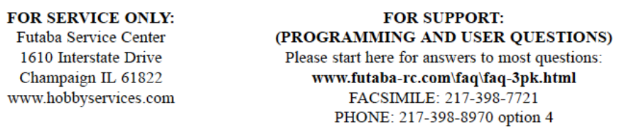
IPK-FSM-2.4G (Transmitter)
PIN ASSIGNMENT
#1
#5
Fig.1 Serial Communication Connector Location
Table 1 Pin Description
Pin Abbreviation I/O Function
1 PPM MOD in Pulse position data VLI 0V VHI 3V
2 Vcc in Vcc:9.6V
3 MET out Transmission indicator
4 GND − signal ground
5 NC − NC
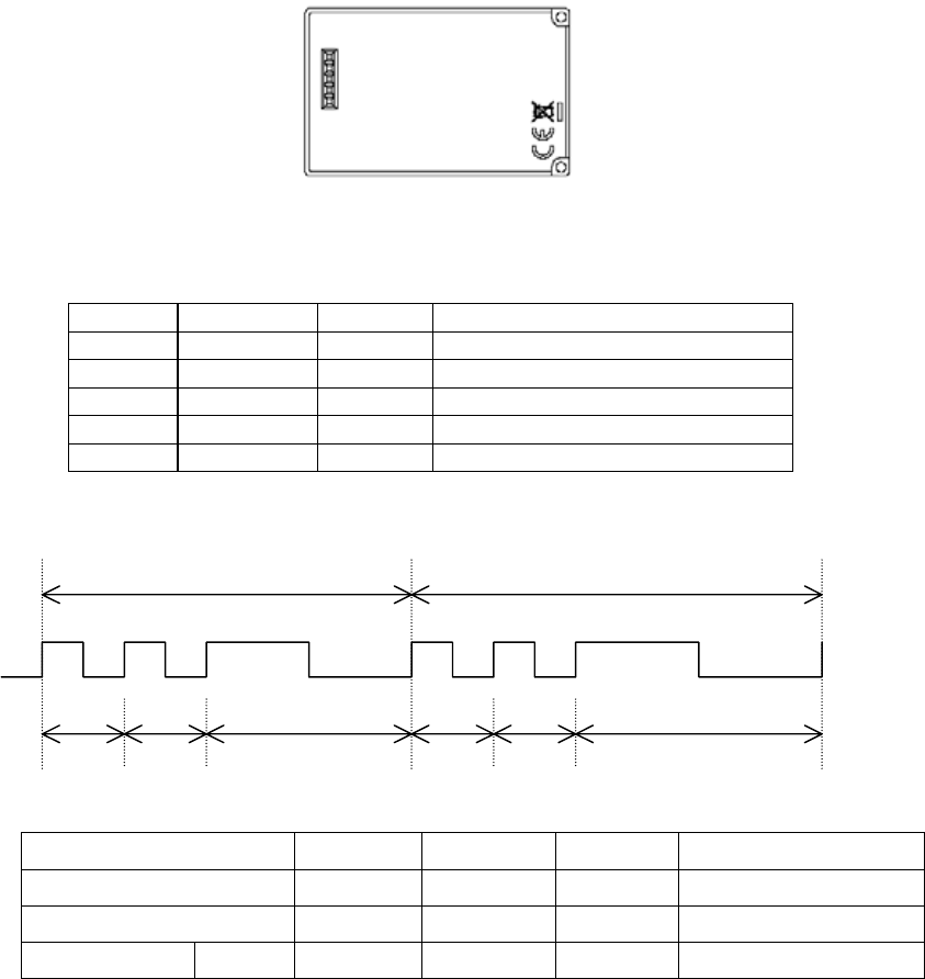
Pulse position data
Data frame Data frame
1ch 2ch 3ch/RESET 1ch 2ch 3ch/RESET
Table 2 Pulse position data
Item minimum center maximum Remarks
【1ch】 800us 1100us 1400us 1100±300us
【2ch】 800us 1100us 1400us 1100±300us
【3ch/RESET】 1500us 1800us 2100us 1800±300us
Set Frequency Pattern in rotary SW(0 or 8)
SW 0 : 2405.376 - 2479.104 MHz 36CH
SW 8 : 2405.376 - 2450.432 MHz 22CH
PK-FSM-2.4G fires an electric wave at the frequency that I set in rotary SW by
power supply re-injection.
3

R603FS(Receiver)
Set frequency SW 1sec PUSH (AUTO SETTING)
Fig.2
4

Frequency Allocation
The PK-FSM-2.4G/R603FS can operate on 36(or22) available frequencies between
2405.376 MHz and 2479.104 MHz with 2.048 MHz separation between each frequency.
See the table below for the exact frequency assignments.
Table 3 :Frequency Channel
Channel
№ Frequency
(MHz) Channel
№ Frequency
(MHz)
02 2405.376 38 2442.240
04 2407.424 40 2444.288
06 2409.472 42 2446.336
08 2411.520 44 2448.384
10 2413.568 46 2450.432
12 2415.616 48 2452.480
14 2417.664 50 2454.528
16 2419.712 52 2456.576
18 2421.760 54 2458.624
20 2423.808 56 2460.672
22 2425.856 58 2462.720
24 2427.904 60 2464.768
26 2429.952 62 2466.816
28 2432.000 64 2468.864
30 2434.048 66 2470.912
32 2436.096 68 2472.960
34 2438.144 70 2475.008
36 2440.192 72 2477.056
74 2479.104
5
Specification
PK-FSM-2.4G SPECIFICATIONS
1 Radio Characteristics
Engineering standard Part 15.247 FCC(U.S.)
RF power output 100mW EIRP
Modulation Direct-Sequence Spread-Spectrum
Communication scheme Single communication
Frequency band 2405.352MHz - 2479.104MHz
Channel 36/22
Data barer rate 136 kbps
6 dB bandwidth 1.6MHz
Frequency control Crystal controlled frequency synthesizer
Antenna 1/2λ Pencil type antenna 1.6dBi
Operating Distance 150m
2 Radio communication control
Error checking CRC-CCITT
3 Terminal interface
Physical interface 5 pins
4 Power Supplying
Supply voltage 9.6V DC
Current consumption 110 mA
5 Environmental
Operating temperature -10 to +60 ℃
Storage temperature -20 to +70 ℃
6 Miscellaneous
Indicator 2 color LED
Frequency setting Rotary SW
Memory register Rewritable times: approx. 1 million times
Case Plastic
Outer dimensions 38 (W)×60(D)×21(H)mm
Weight Aprox. 35g
R603FS SPECIFICATIONS
1 Radio Characteristics
Engineering standard Part 15.247 FCC(U.S.)
Frequency band 2405.352MHz - 2479.104MHz
Channel 36/22
Data barer rate 136 kbps
Frequency control Crystal controlled frequency synthesizer
Antenna 1/2λ SMD type antenna -5dBi
Operating Distance 150m
2 Radio communication control
Error checking CRC-CCITT
3 Terminal interface
Physical interface 15 pins
4 Power Supplying
Supply voltage 6V DC
Current consumption 80 mA
5 Environmental
Operating temperature -10 to +60 ℃
Storage temperature -20 to +70 ℃
6 Miscellaneous
Indicator 2 color LED
Memory register Rewritable times: approx. 1 million times
Case Plastic
Outer dimensions 26(W)×40(D)×14.5(H)mm
Weight Aprox. 14g
6