Futaba R6308SBT-24G Radio Control User Manual
Futaba Corporation Radio Control
UserManual.wiki
>
Futaba
>
R6308SBT-24G User Manual
>
User Manual
Contents
1.
Spec.-Rev.01(0516)
2.
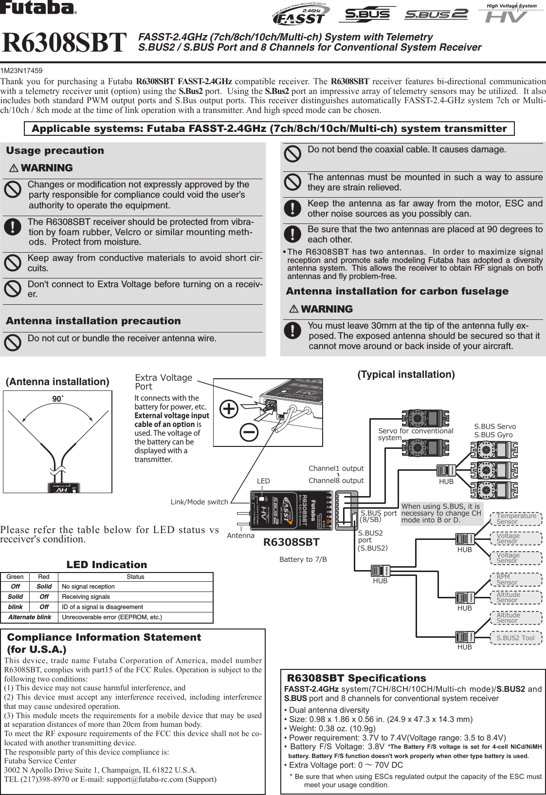
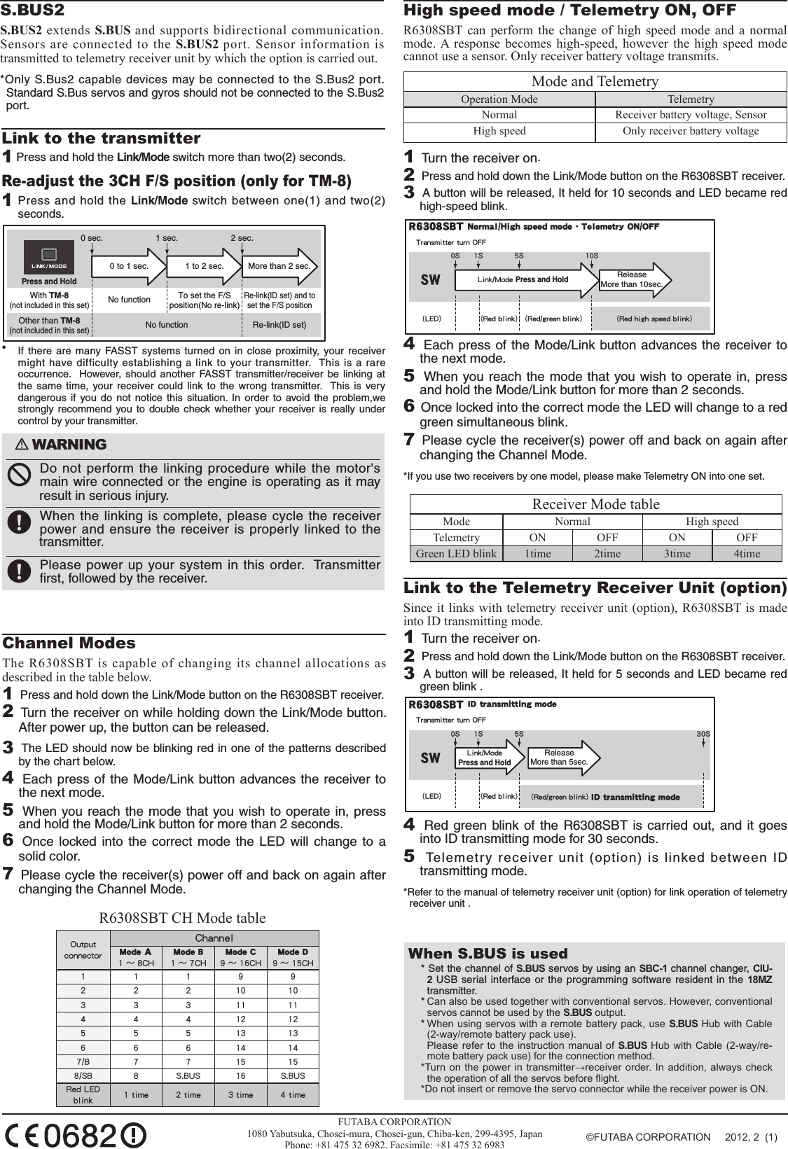
User Manual
User Manual
Navigation menu
Upload a User Manual
Namespaces
Wiki Guide
HTML
PDF
Info
Views
User Manual
Discussion / Help
Navigation