Contents
- 1. Spec.-Rev.01(0516)
- 2. User Manual
User Manual
Applicable systems: Futaba FASST-2.4GHz (7ch/8ch/10ch/Multi-ch) system transmitter
R6308SBT FASST-2.4GHz (7ch/8ch/10ch/Multi-ch) System with Telemetry
S.BUS2 / S.BUS Port and 8 Channels for Conventional System Receiver
Compliance Information Statement
(for U.S.A.)
This device, trade name Futaba Corporation of America, model number
R6308SBT, complies with part15 of the FCC Rules. Operation is subject to the
following two conditions:
(1) This device may not cause harmful interference, and
(2) This device must accept any interference received, including interference
that may cause undesired operation.
(3) This module meets the requirements for a mobile device that may be used
at separation distances of more than 20cm from human body.
To meet the RF exposure requirements of the FCC this device shall not be co-
located with another transmitting device.
The responsible party of this device compliance is:
Futaba Service Center
3002 N Apollo Drive Suite 1, Champaign, IL 61822 U.S.A.
TEL (217)398-8970 or E-mail: support@futaba-rc.com (Support)
R6308SBT Specications
FASST-2.4GHz system(7CH/8CH/10CH/Multi-ch mode)/S.BUS2 and
S.BUS port and 8 channels for conventional system receiver
• Dual antenna diversity
• Size: 0.98 x 1.86 x 0.56 in. (24.9 x 47.3 x 14.3 mm)
• Weight: 0.38 oz. (10.9g)
• Power requirement: 3.7V to 7.4V(Voltage range: 3.5 to 8.4V)
• Battery F/S Voltage: 3.8V *The Battery F/S voltage is set for 4-cell NiCd/NiMH
battery. Battery F/S function doesn't work properly when other type battery is used.
• Extra Voltage port: 0 ~70V DC
* Be sure that when using ESCs regulated output the capacity of the ESC must
meet your usage condition.
Thank you for purchasing a Futaba R6308SBT FASST-2.4GHz compatible receiver. The R6308SBT receiver features bi-directional communication
with a telemetry receiver unit (option) using the S.Bus2 port. Using the S.Bus2 port an impressive array of telemetry sensors may be utilized. It also
includes both standard PWM output ports and S.Bus output ports. This receiver distinguishes automatically FASST-2.4-GHz system 7ch or Multi-
ch/10ch / 8ch mode at the time of link operation with a transmitter. And high speed mode can be chosen.
LED Indication
Green Red Status
Off Solid No signal reception
Solid Off Receiving signals
blink Off ID of a signal is disagreement
Alternate blink Unrecoverable error (EEPROM, etc.)
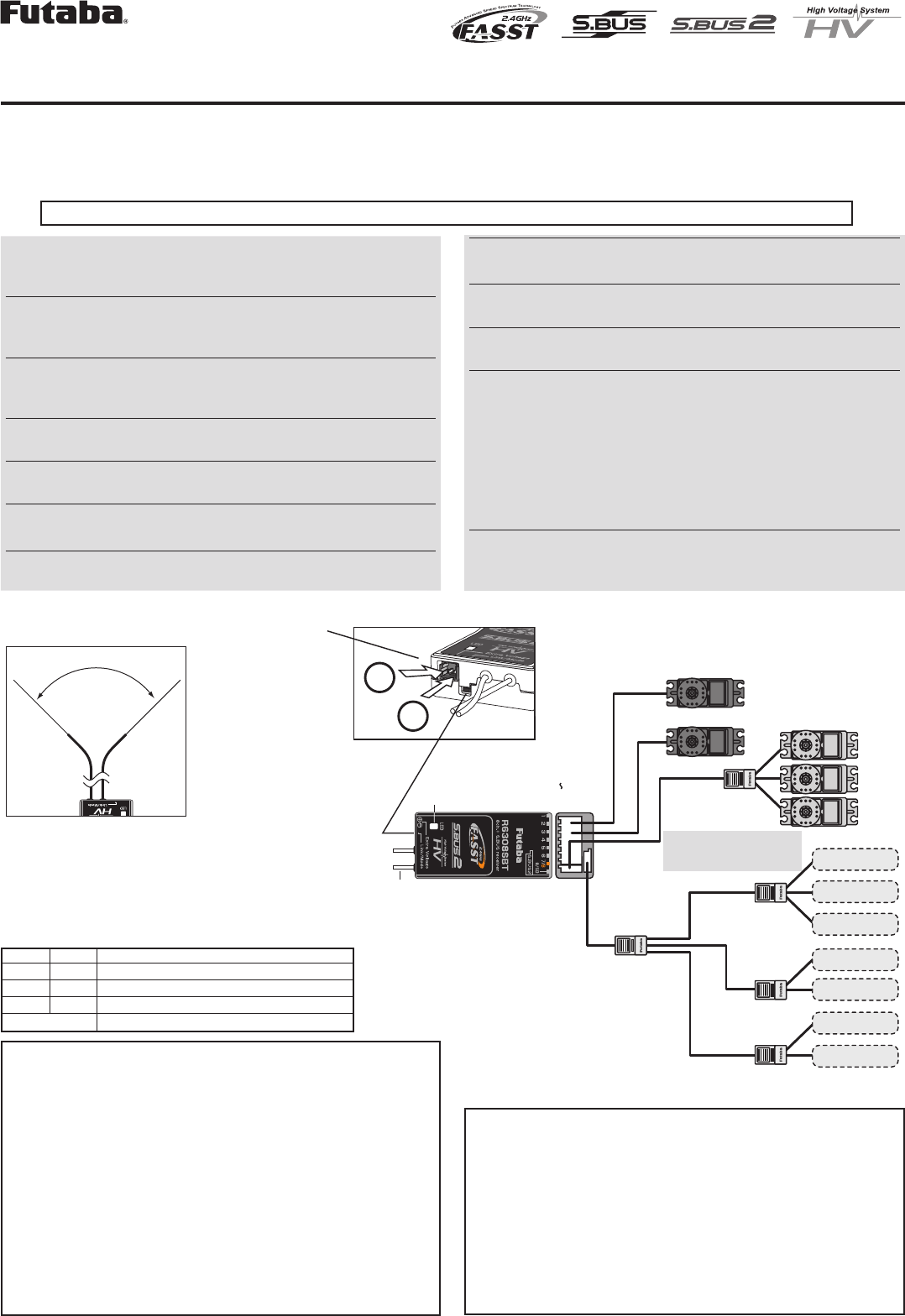
(Antenna installation)
90˚
Please refer the table below for LED status vs
receiver's condition.
1M23N17459
S.BUS2
port
S.BUS port
(8/SB)
(S.BUS2)
R6308SBT
S.BUS Servo
S.BUS Gyro
HUB
HUB
HUB
HUB
Extra Voltage
Port
Link/Mode switch
Antenna
LED
Servo for conventional
system
Channel1 output
Channel8 output
Temperature
Sensor
RPM
Sensor
Voltage
Sensor
Voltage
Sensor
Altitude
Sensor
Altitude
Sensor
S.BUS2 Tool
Battery to 7/B
+
−
It connects with the
battery for power, etc.
External voltage input
cable of an option is
used. The voltage of
the battery can be
displayed with a
transmitter.
with telemetry
When using S.BUS, it is
necessary to change CH
mode into B or D.
HUB
Usage precaution
WARNING
Changes or modification not expressly approved by the
party responsible for compliance could void the user’s
authority to operate the equipment.
The R6308SBT receiver should be protected from vibra-
tion by foam rubber, Velcro or similar mounting meth-
ods. Protect from moisture.
Keep away from conductive materials to avoid short cir-
cuits.
Don't connect to Extra Voltage before turning on a receiv-
er.
Antenna installation precaution
Do not cut or bundle the receiver antenna wire.
Do not bend the coaxial cable. It causes damage.
The antennas must be mounted in such a way to assure
they are strain relieved.
Keep the antenna as far away from the motor, ESC and
other noise sources as you possibly can.
Be sure that the two antennas are placed at 90 degrees to
each other.
•TheR6308SBThastwoantennas.Inordertomaximizesignal
reception and promote safe modeling Futaba has adopted a diversity
antenna system. This allows the receiver to obtain RF signals on both
antennas and fly problem-free.
Antenna installation for carbon fuselage
WARNING
You must leave 30mm at the tip of the antenna fully ex-
posed. The exposed antenna should be secured so that it
cannot move around or back inside of your aircraft.
(Typical installation)
When S.BUS is used
* Set the channel of S.BUS servos by using an SBC-1 channel changer, CIU-
2 USB serial interface or the programming software resident in the 18MZ
transmitter.
* Can also be used together with conventional servos. However, conventional
servos cannot be used by the S.BUS output.
* When using servos with a remote battery pack, use S.BUS Hub with Cable
(2-way/remote battery pack use).
Please refer to the instruction manual of S.BUS Hub with Cable (2-way/re-
mote battery pack use) for the connection method.
*Turn on the power in transmitter→receiver order. In addition, always check
the operation of all the servos before ight.
*Do not insert or remove the servo connector while the receiver power is ON.
WARNING
Do not perform the linking procedure while the motor's
main wire connected or the engine is operating as it may
result in serious injury.
When the linking is complete, please cycle the receiver
power and ensure the receiver is properly linked to the
transmitter.
Please power up your system in this order. Transmitter
first, followed by the receiver.
FUTABA CORPORATION
1080 Yabutsuka, Chosei-mura, Chosei-gun, Chiba-ken, 299-4395, Japan
Phone: +81 475 32 6982, Facsimile: +81 475 32 6983
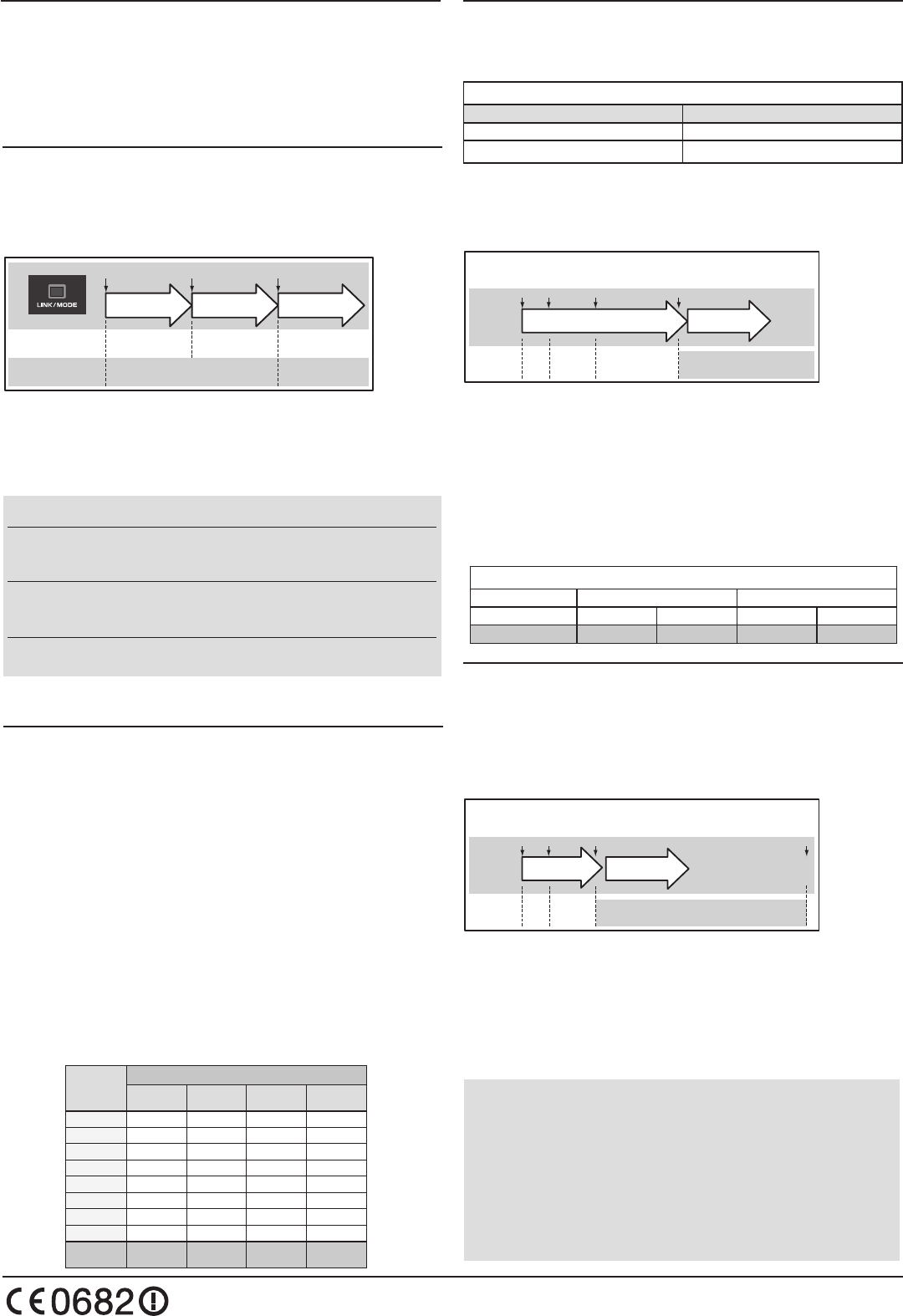
Link to the transmitter
1 Press and hold the Link/Mode switch more than two(2) seconds.
Re-adjust the 3CH F/S position (only for TM-8)
1 Press and hold the Link/Mode switch between one(1) and two(2)
seconds.
0 to 1 sec. 1 to 2 sec. More than 2 sec.
0 sec. 1 sec. 2 sec.
Press and Hold
No function
With TM-8
(not included in this set)
To set the F/S
position(No re-link)
Re-link(ID set) and to
set the F/S position
No function
Other than TM-8
(not included in this set)
Re-link(ID set)
• If there are many FASST systems turned on in close proximity, your receiver
might have difficulty establishing a link to your transmitter. This is a rare
occurrence. However, should another FASST transmitter/receiver be linking at
the same time, your receiver could link to the wrong transmitter. This is very
dangerous if you do not notice this situation. In order to avoid the problem,we
strongly recommend you to double check whether your receiver is really under
control by your transmitter.
Channel Modes
The R6308SBT is capable of changing its channel allocations as
described in the table below.
1 Press and hold down the Link/Mode button on the R6308SBT receiver.
2 Turn the receiver on while holding down the Link/Mode button.
After power up, the button can be released.
3 The LED should now be blinking red in one of the patterns described
by the chart below.
4 Each press of the Mode/Link button advances the receiver to
the next mode.
5 When you reach the mode that you wish to operate in, press
and hold the Mode/Link button for more than 2 seconds.
6 Once locked into the correct mode the LED will change to a
solid color.
7 Please cycle the receiver(s) power off and back on again after
changing the Channel Mode.
S.BUS2
S.BUS2 extends S.BUS and supports bidirectional communication.
Sensors are connected to the S.BUS2 port. Sensor information is
transmitted to telemetry receiver unit by which the option is carried out.
*Only S.Bus2 capable devices may be connected to the S.Bus2 port.
Standard S.Bus servos and gyros should not be connected to the S.Bus2
port.
High speed mode / Telemetry ON, OFF
R6308SBT can perform the change of high speed mode and a normal
mode. A response becomes high-speed, however the high speed mode
cannot use a sensor. Only receiver battery voltage transmits.
Mode and Telemetry
Operation Mode Telemetry
Normal Receiver battery voltage, Sensor
High speed Only receiver battery voltage
1 Turn the receiver on.
2 Press and hold down the Link/Mode button on the R6308SBT receiver.
3 A button will be released, It held for 10 seconds and LED became red
high-speed blink.
R6308SBT Normal/High speed mode・Telemetry ON/OFF
Link/Mode
Press and Hold
Transmitter turn OFF
Release
More than 10sec.
0S 5S
SW
(Red blink) (Red/green blink) (Red high speed blink)
(LED)
10S1S
4 Each press of the Mode/Link button advances the receiver to
the next mode.
5 When you reach the mode that you wish to operate in, press
and hold the Mode/Link button for more than 2 seconds.
6 Once locked into the correct mode the LED will change to a red
green simultaneous blink.
7 Please cycle the receiver(s) power off and back on again after
changing the Channel Mode.
*If you use two receivers by one model, please make Telemetry ON into one set.
Receiver Mode table
Mode Normal High speed
Telemetry ON OFF ON OFF
Green LED blink 1time 2time 3time 4time
Link to the Telemetry Receiver Unit (option)
Since it links with telemetry receiver unit (option), R6308SBT is made
into ID transmitting mode.
1 Turn the receiver on.
2 Press and hold down the Link/Mode button on the R6308SBT receiver.
3 A button will be released, It held for 5 seconds and LED became red
green blink .
R6308SBT ID transmitting mode
Link/Mode
Press and Hold
Transmitter turn OFF
Release
More than 5sec.
0S 5S
SW
(Red blink) (Red/green blink) ID transmitting mode
(LED)
30S1S
4 Red green blink of the R6308SBT is carried out, and it goes
into ID transmitting mode for 30 seconds.
5 Telemetry receiver unit (option) is linked between ID
transmitting mode.
*Refer to the manual of telemetry receiver unit (option) for link operation of telemetry
receiver unit .
Output
connector
Channel
Mode A
1 ~ 8CH
Mode B
1 ~ 7CH
Mode C
9 ~ 16CH
Mode D
9 ~ 15CH
11199
2 2 2 10 10
3 3 3 11 11
4 4 4 12 12
5 5 5 13 13
6 6 6 14 14
7/B 7 7 15 15
8/SB 8 S.BUS 16 S.BUS
Red LED
blink 1 time 2 time 3 time 4 time
R6308SBT CH Mode table
©FUTABA CORPORATION 2012, 2 (1)