User Manual
Applicable systems: Futaba FASSTest-2.4GHz system-
transmitter
If R7003SB does not use S.BUS/S.BUS2 system, it can
perform only operation of 3 channels. However, if S.BUS/
S.BUS2 system is used, use of the maximum channel of
a transmitter can be performed. You have to use S.BUS/
S.BUS2 servo, in order to use S.BUS/S.BUS2 system.
R7003SB FASSTest-2.4GHz Bidirectional Communication System
S.BUS2 / S.BUS Port and Conventional System Receiver
Compliance Information Statement
(for U.S.A.)
This device, trade name Futaba Corporation of America, model number R7003SB, complies with
part15 of the FCC Rules. Operation is subject to the following two conditions:
(1) This device may not cause harmful interference, and
(2) This device must accept any interference received, including interference that may cause
undesired operation.
(3) This module meets the requirements for a mobile device that may be used at separation distances
of more than 20cm from human body.
To meet the RF exposure requirements of the FCC this device shall not be co-located with another
transmitting device.
The responsible party of this device compliance is:
Futaba Service Center
3002 N Apollo Drive Suite 1, Champaign, IL 61822 U.S.A.
TEL (217)398-8970 or E-mail: support@futaba-rc.com (Support)
R7003SB Specications
FASSTest-2.4GHz system/S.BUS2 and S.BUS port and conventional system receiver
• Dual antenna diversity
• Size: 0.89 x 1.47 x 0.37 in. (22.5 x 37.4 x 9.3 mm)
• Weight: 0.25 oz. (7.2g)
• Power requirement: 3.7V to 7.4V(Voltage range: 3.5 to 8.4V)
• Battery F/S Voltage: It sets up with a transmitter
• Extra Voltage port (port2)"EXT-VOL cable and CA-RVIN-700" of an option is used: 0 ~70V DC
* Be sure that when using ESCs regulated output the capacity of the ESC must meet your usage condition.
Thank you for purchasing a Futaba R7003SB FASSTest-2.4GHz compatible
receiver. The R7003SB receiver features bi-directional communication with a
FASSTest Futaba transmitter using the S.BUS2 port. Using the S.BUS2 port
an impressive array of telemetry sensors may be utilized. R7003SB has a
merit which acquires the information from the model on ight by connecting an
optional telemetry sensors. It also includes both standard PWM output ports and
S.BUS output ports. 4 ports of R7003SB can choose an output channel from the
11 modes.
LED Indication
Green Red Status
Off Solid No signal reception
Solid Off Receiving signals
Alternate blink Unrecoverable error (EEPROM, etc.)
FASSTest
FASSTest is a bidirectional communication system between the R7003SB receiver and
FASSTest capable transmitters. Multiple optional telemetry sensors may be connected to
the S.BUS2 on the receiver and that data is in turn displayed on the transmitter.
*Please see your transmitters operation manual to configure transmitter to operate with
telemetry sensors.
(Antenna installation)
90˚ Please refer the table below for LED status vs
receiver's condition.
1M23N17470
Usage precaution
•AnalogservoscannotbeusedwiththeR7003SBintheFASSTest12CHmode.
•TheR7003SBreceivercanonlybeusedwithFASSTestcapabletransmitters.
WARNING
Changesormodicationnotexpresslyapprovedbythepartyresponsible
for compliance could void the user’s authority to operate the equipment.
TheR7003SBreceivershouldbeprotectedfromvibrationbyfoamrubber,
Velcro or similar mounting methods. Protect from moisture.
Keep away from conductive materials to avoid short circuits.
Don'tconnecttheservoorgyrowhichdonotcorrespondtoS.BUS2port
S.BUS2.
•WhentheservoandgyrowhichdonotcorrespondtoS.BUS2areconnectedtoS.BUS2
port, there is a danger of falling by malfunction.
Turnonthepowerintransmitter →receiver order. In addition, always check
the operation of all the servos before flight.
Do not insert or remove the servo connector while the receiver power is
ON.
•SincetheS.BUS servo switchestheoperationmodeautomaticallyaccordingtothe
typeof signal (S.BUSsignal/PWM signal) fromthe receiver, if theconnector is inserted
or removedwhilethe power isON,anS.BUSconnected servo willbeerroneously
recognized and may stop.
Antenna installation precaution
Do not cut or bundle the receiver antenna wire.
Donotbendthecoaxialcable.Itcausesdamage.
Theantennasmustbemounted insuchawaytoassuretheyarestrain
relieved.
Keeptheantennaasfarawayfromthemotor,ESCandothernoisesources
as you possibly can.
Besurethatthetwoantennasareplacedat90degreestoeachother.
•The R7003SBhastwo antennas. Inorderto maximizesignalreception and
promotesafemodelingFutabahas adoptedadiversityantennasystem. This allowsthe
receivertoobtainRFsignalsonbothantennasandyproblem-free.
Antenna installation for carbon fuselage
WARNING
Youmustleave30mmatthetipoftheantennafullyexposed.Theexposed
antenna should be secured so that it cannot move around or back inside of
your aircraft.
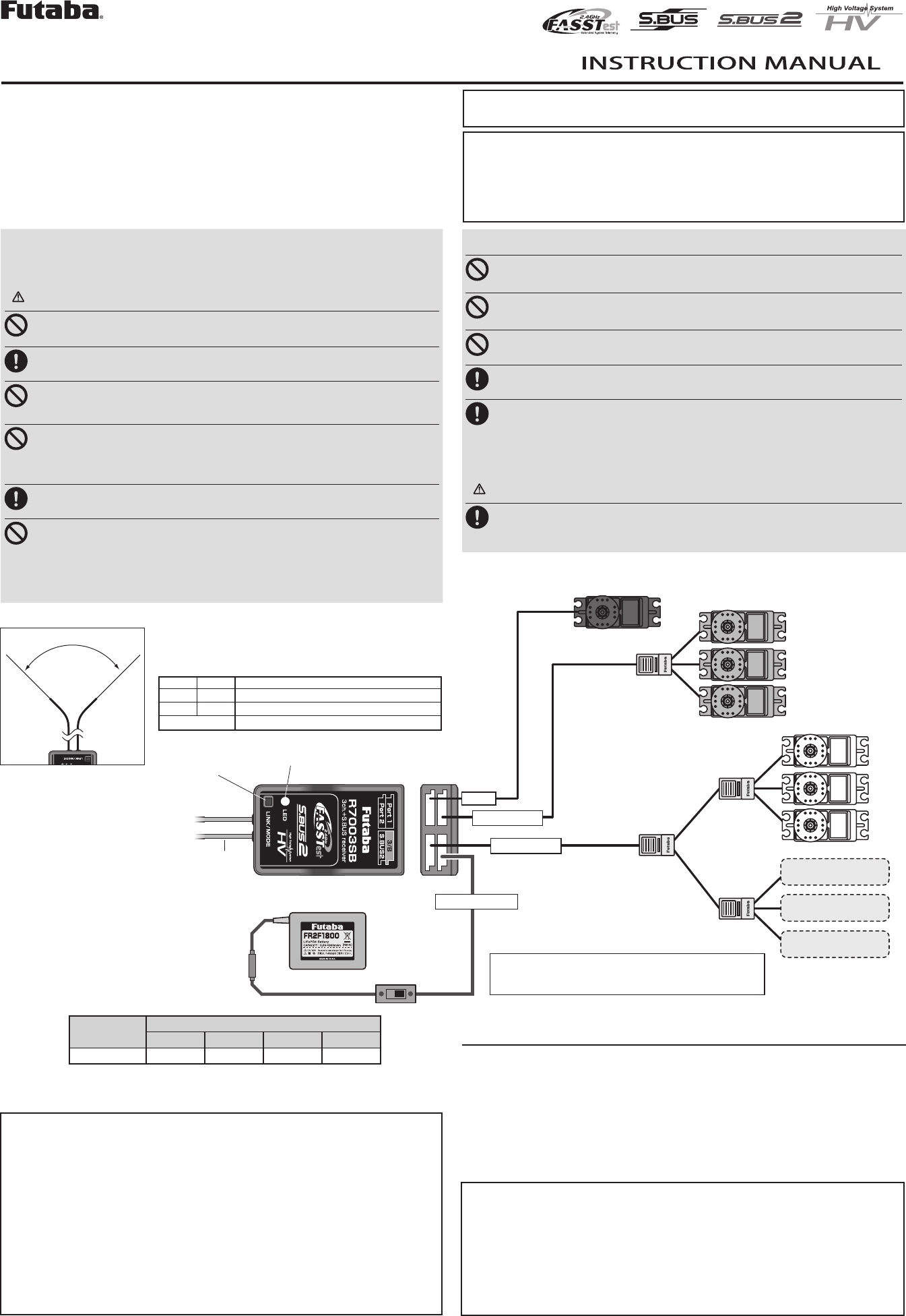
(Typical installation)
S.BUS Servo
S.BUS2 Servo
S.BUS2 Gyro
HUB
HUB
HUB
HUB
Link/Mode switch
Antenna
LED
Servo for conventional
system
Battery
SW
(It is not used for a link.) R7003SB
CH output mode A (Default)
Example
Temperature
Sensor
RPM
Sensor
Altitude
Sensor
S.BUS port 1
S.BUS2 port
Battery to 3/B
A battery is connectable
also with which port.
port 2
Mode Port
Port1 Port2 3/B S.BUS2
A(Default) S.BUS CH2 CH3 S.BUS2
WARNING
Do not perform the linking procedure while the motor's main wire connected
or the engine is operating as it may result in serious injury.
Whenthelinkingiscomplete,pleasecyclethereceiverpowerandensure
the receiver is properly linked to the transmitter.
Pleasepowerupyoursysteminthisorder.Transmitterrst,followedbythe
receiver.
IftheR7003SBreceiverwaspreviouslylinkedtoanothertransmitter,make
sure that transmitter is not operating while linking the receiver to the new
transmitter.
WARNING
Don't touch wiring.
* There is a danger of receiving an electric shock.
Don'tconnecttoExtraVoltagebeforeturningonareceiver.
WhennotusingEXT-VOL,"EXT-VOLMode"isturnedOFF.
Don'tconnectEXT-VOLCABLEotherthanport2ofR7003SB.
FUTABA CORPORATION
1080 Yabutsuka, Chosei-mura, Chosei-gun, Chiba-ken, 299-4395, Japan
Phone: +81 475 32 6982, Facsimile: +81 475 32 6983
Link to the transmitter
Easy Link ID allows FASSTest receivers to link to compatible transmitter without pressing
the link button on the receiver.
1Bringthetransmitterandthereceiverclosetoeachother,within20inches(half
meter).
2 Turnonthetransmitter.Placethetransmitterintothereceiverlinkingmode.
3Turnonthereceiver.
4 WhentheLEDofthereceiverchangesfromblinkingredtosolid green, linking
is complete.
* Refer to the transmitters operation manual for complete details on how to place the transmitter into the
linking mode.
*If there are many FASSTest systems turned on in close proximity, your receiver might have difculty
establishing a link to your transmitter. This is a rare occurrence. However, should another FASSTest
transmitter/receiverbelinkingatthesametime,yourreceivercouldlinktothewrongtransmitter.Thisis
very dangerous if you do not notice this situation. In order to avoid the problem,we strongly recommend
you to double check whether your receiver is really under control by your transmitter.
*IftheSystemTypeofthetransmitterischanged,thereceiverwillneedtobere-linkedtothetransmitter.
*Linkisrequiredwhenanewmodelismadefromamodelselection.
< How to change R7003SB into "EXT-VOL Mode" >
1 Turnonthereceiver. LED lights up red. [TransmitterisalwaysOFF]
2 PressandholdtheMode/Linkbuttonfor5secondsto10seconds.
*It becomes the mode which makes a mistake in exceeding 10 seconds. In that case, carry out power
supply OFF and redo.
3TheLEDshouldnowbeearlyblinkinggreen.Mode/Linkbuttonisreleased.
4 EachpressoftheMode/Linkbuttonadvancesthereceivertothenextmode.
5 Whenyoureachthemodethatyouwishtooperatein,pressandholdtheMode/
Linkbuttonformorethan2seconds.
6 WhenLEDblinksingreenwithred,itisthecompletionofamodechange.
7 PleasecyclethereceiverpoweroffandbackonagainafterchangingtheEXT-
VOLMode.
Mode External voltage
measurement LED blink
Servo Mode(Default) OFF Green 1 time
EXT-VOL Mode ON Green 2 time
Measurement of Extra Voltag
R7003SB can display the voltage of a receiver battery on a transmitter.
Furthermore, the following procedures are required in order to display the voltage of
another battery (Drive battery etc.).
1TheoptionaladapterforCA-RVIN-700ispurchased.
2 R7003SBischangedinto"EXT-VOLMode"inthefollowing procedure.
*If"EXT-VOLMode"isused,theport2cannotbeusedastheservoCH.
3 According to the manual of CA-RVIN-700, battery wiring is branched and it
connects.
4OnesideofEXT-VOLCABLEisconnectedtotheport2ofR7003SB.
Channel Modes
The R7003SB is capable of changing its channel allocations as described in the table
below. Please choose the mode which suited the use in the following procedure from the
11 modes.
1PressandholddowntheLink/ModebuttonontheR7003SBreceiver.
[TransmitterisalwaysOFF]
2 TurnthereceiveronwhileholdingdowntheLink/Modebutton.Afterpowerup,
the button can be released.
3TheLEDshouldnowbeblinkingredwithgreen.
4 EachpressoftheMode/Linkbuttonadvancesthereceivertothenextmode.
[RefertoCHModetableshownbelow.]
5 When you reach the mode that you wish to operate in, press and hold the
Mode/Linkbuttonformorethan2seconds.
6 WhenLEDblinksingreenwithred,itisthecompletionofamodechange.
7 Please cycle the receiver power off and back on again after changing the
ChannelMode.
*5secondsafterthereceiverON,LEDshowsCHMode.
S.BUS2
S.BUS2 extends S.BUS and supports bidirectional communication. Sensors are connected
to the S.BUS2 port.
*Only S.BUS2 capable devices may be connected to the S.BUS2 port. Standard S.BUS
servosandgyrosshouldnotbeconnectedtotheS.BUS2port.
R7003SB CH Mode table
©FUTABA CORPORATION 2012, 10 (1)
Mode Port LED blink
Port1 Port2 3/B S.BUS2
A(Default) S.BUS
CH2
CH3
S.BUS2 Red 1 time
BS.BUS2 Red 2 time
CS.BUS S.BUS Red 3 time
D
CH1
Red 4 time
E
S.BUS2
Green 1 time
FCH4 Green 2 time
GCH2 Green 3 time
HCH1 CH5 Green 4 time
ICH2 CH7 Red and Green 1 time
JCH4 CH8 Red and Green 2 time
KCH11 CH12 Red and Green 3 time
Port S.BUS Servo
S.BUS Gyro
S.BUS2 Servo
S.BUS2 Gyro Telemetry sensor
S.BUS ○ ○ ×
S.BUS2 × (*) ○ ○
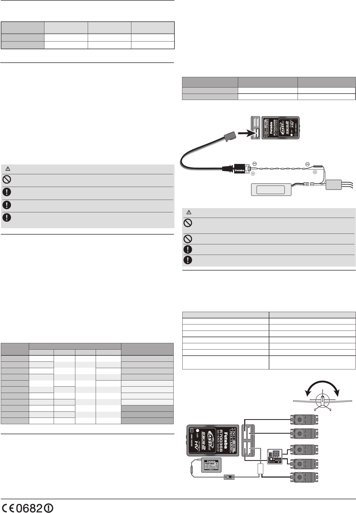
R7003SB
[ Example: Connecting GYA431 to R7003SB CH Mode G ]
(GYA431 is used for the aileron of an airplane)
CH4
Rudder servo
CH6
2nd Aileron servo
CH2
Elevator servo
Port 1
Port 2
S.BUS2
3/B CH1
Aileron servo
Battery CH3
Throttle servo
GYA431
HUB
When using the R7003SB Receiver with the GYA430,
GYA431 and CGY750
The following table corresponds to the gyro's functions. A port can be used effectively.
The servo which a gyro controls is connected to a gyro.
* Please refer to the description of each gyro manual.
Gyro control CH CH Mode
Rudder D,E
Elevator F
Aileron G
Elevator+Rudder H
Aileron+Rudder I
Aileron+Elevator J
Aileron+Elevator+Rudder
or CGY750 K
S.BUS Gyro Goup table
with external power
input must be less than 70V
To Motor Controller
or Servo
Branch
Fuse
Black line
Red line
Motor
Controller
EXT-VOL CABLE
(It is attached to R7003SB.) (Option)
EXT-VOL CABLE
to Port2
*It changes into EXT-VOL Mode
R7003SB
to Motor
EXT-VOL
Power Battery or
another power supply
for servos
*It connects with reference to the manual of CA-RVIN-700.