Futaba R7006SB-24G Radio Control User Manual
Futaba Corporation Radio Control
UserManual.wiki
>
Futaba
>
R7006SB 24G User Manual
User Manual
Navigation menu
Upload a User Manual
Namespaces
Wiki Guide
HTML
PDF
Info
Views
User Manual
Discussion / Help
Navigation
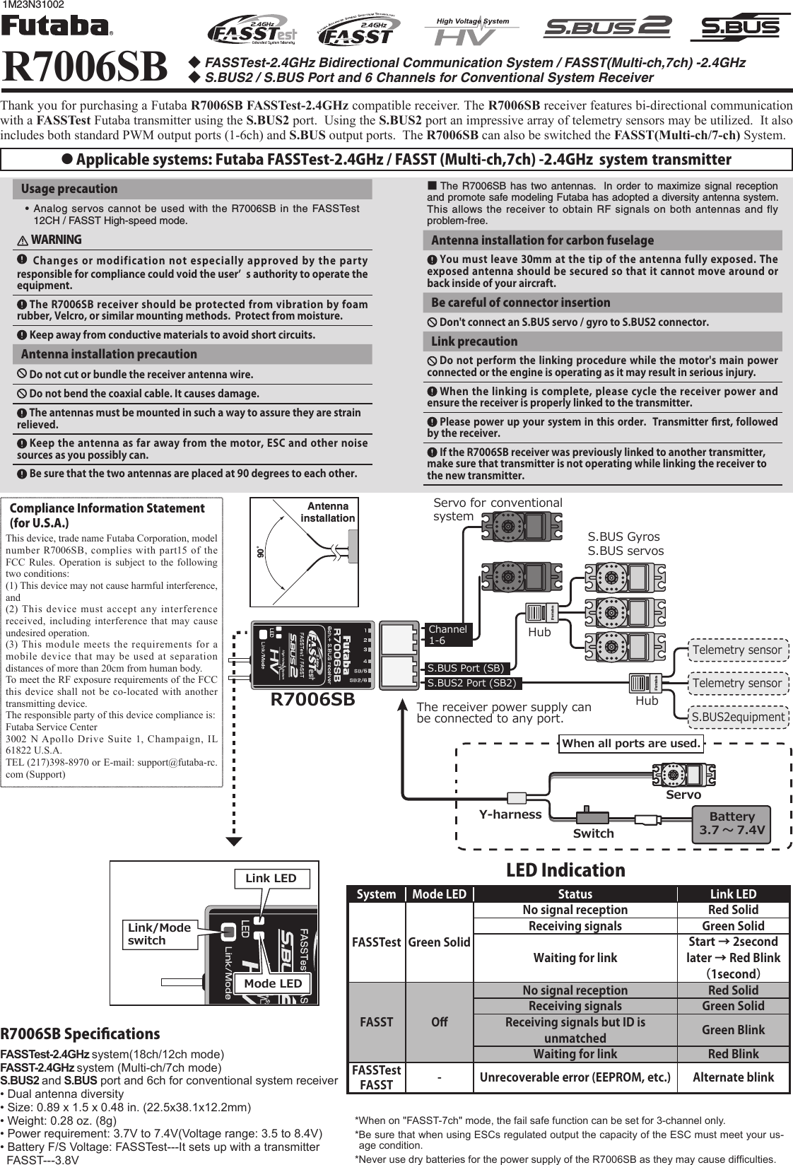
![Green LED blink System1 time FASSTest2 times FASST Multi-ch Normal mode3 times FASST Multi-ch High-speed mode4 times FASST 7ch Normal mode5 times FASST 7ch High-speed modeR7006SB System tableOutputconnectorChannelMode A Mode B Mode C Mode D111192 2 2 2 103 3 3 3 114 4 4 4 125/SB 5 S.BUS 6 S.BUS6/SB2 6 S.BUS2 S.BUS2 S.BUS2Red LED blink 1 time 2 times 3 times 4 timesR7006SB CH Mode tableDefault*The telemetry cannot be used with the FASST system.Channel ModesThe R7006SB is capable of changing its channel allocations as described in the table below. This is especially important when using the receiver in a dual receiver mode. See your transmitter operation manual for complete details on operating in the dual receiver mode. 1 Turn on the receiver. [Transmitter is always OFF]2 Press and hold the Mode/Link button for 5 seconds to 10 seconds.3 When the LED of the receiver changes from blinking red to blinking red with green, Mode/Link button is released.4 The LED should now be blinking red in 2 times of the patterns described by the chart below.5 Each press of the Mode/Link button advances the receiver to the next mode.6 When you reach the mode that you wish to operate in, press and hold the Mode/Link button for more than 2 seconds. When LED blinks in green with red, it is the completion of a mode change, Mode/Link button is released.7 Please cycle the receiver power off and back on again after changing the Channel mode.Systems (FASSTest ⇔FASST) change method 1 Turn on the receiver. [Transmitter is always OFF]2 Press and hold the Link/Mode button for more then 10 seconds. 3 When the LED begins to blink green the button may be released.4 The LED should now be blinking green in one of the patterns described by the chart below. ( Default : FASSTest )5 Each press of the Mode/Link button advances the receiver to the next system.6 When you reach the system that you wish to operate in, press and hold the Mode/Link button for more than 2 seconds. When LED blinks in green with red, it is the completion of a system change, Mode/Link button is released.7 Please cycle the receiver power off and back on again after changing the system.DefaultFASSTest is a bidirectional communication system between the R7006SB receiver and FASSTest capable transmitters. Multiple optional telemetry sensors may be connected to the S.BUS2 on the receiver and that data is in turn displayed on the transmitter.Link to the transmitter : FASSTest1 Bring the transmitter and the receiver close to each other, within 20 inches (half meter).2 Turn on the transmitter. Place the transmitter into the receiver linking mode.3 Turn on the receiver.4 The receiver will wait for the linking process to begin for 2 seconds. Following that it will return to the normal operation mode.5 When the LED of the receiver changes from blinking red to solid green, linking is complete. (A link waiting state is ended in 1 second.)• Refer to the transmitters operation manual for complete details on how to place the transmitter into the linking mode.• If there are many FASSTest systems turned on in close proximity, your receiver might have difficulty establishing a link to your transmitter. This is a rare occurrence. However, should another FASSTest transmitter/receiver be linking at the same time, your receiver could link to the wrong transmitter. This is very dangerous if you do not notice this situation. In order to avoid the problem,we strongly recommend you to double check whether your receiver is really under control by your transmitter. • If the System Type of the transmitter is changed, the receiver will need to be re-linked to the transmitter.Link to the TMA-1 Telemetry Adapter1 R7006SB has to be FASSTest.2 First, a transmitter and a receiver are linked.3 Transmitter is turned off. 4 Press and hold the Mode/Link button of R7006SB for 15 seconds.5 When LED of R7006SB, Red Blink → Red with green Blink → Green Blink → Red Blink → Mode/Link button is released.6 R7006SB was link mode with TMA-1. The LED blinks in green with red of R7006SB.7 The link button of TMA-1 is pushed for a long time to LED blink.8 Completion of a link will change LED of TMA-1 green from red only for a moment. 9 Please cycle the receiver power.S.BUS2 S.BUS2 extends S.BUS and supports bidirectional communication. Sensors are connected to the S.BUS2 port.Link to the transmitter : FASST1 Bring the transmitter and the receiver close to each other, within 20 inches (half meter).2 Turn on the transmitter and receiver.3 Link operation is performed by the Link/Mode switch.• When using TM-8 module, it's possible to set F/S position (only 3CH).0 to 1 sec. 1 to 2 sec. More than 2 sec.0 sec. 1 sec. 2 sec.Press and Hold timeNo functionWith TM-8(not included in this set)To set the F/S position(No re-link)Re-link(ID set) and to set the F/S positionNo functionBesides TM-8 Re-link(ID set)*Refer to the instruction manual of the transmitter or module used for a description of the linking operation, F/S position setting methods and other details.When switched, the R7006SB can use the FASST-Multi/7ch mode. When the FASST system is used, the telemetry cannot be used. The FASST system has a Normal mode and a High-speed mode. However, in the High-speed mode, analog servos cannot be used.FASSTestFASSTFUTABA CORPORATION1080 Yabutsuka, Chosei-mura, Chosei-gun, Chiba-ken, 299-4395, JapanPhone: +81 475 32 6982, Facsimile: +81 475 32 6983©FUTABA CORPORATION 2015, 11 (1)本產品符合低功率電波輻射性電機管理辦法 第十二條、第十四條等條文規定1. 經型式認證合格之低功率射頻電機,非經許可,公司、商號或使用者均不得擅自變更頻率、加大功率或變更原設計之特性及功能。2. 低功率射頻電機之使用不得影響飛航安全及干擾合法通信;經發現有干擾現象時,應立即停用,並改善至無干擾時方得繼續使用。前項合法通信,指依電信法規定作業之無線電通信。低功率射頻電機須忍受合法通信或工業、科學及醫療用電波輻射性電機設備之干擾。](https://usermanual.wiki/Futaba/R7006SB-24G/User-Guide-2869488-Page-2.png)