User Manual
R7006SB
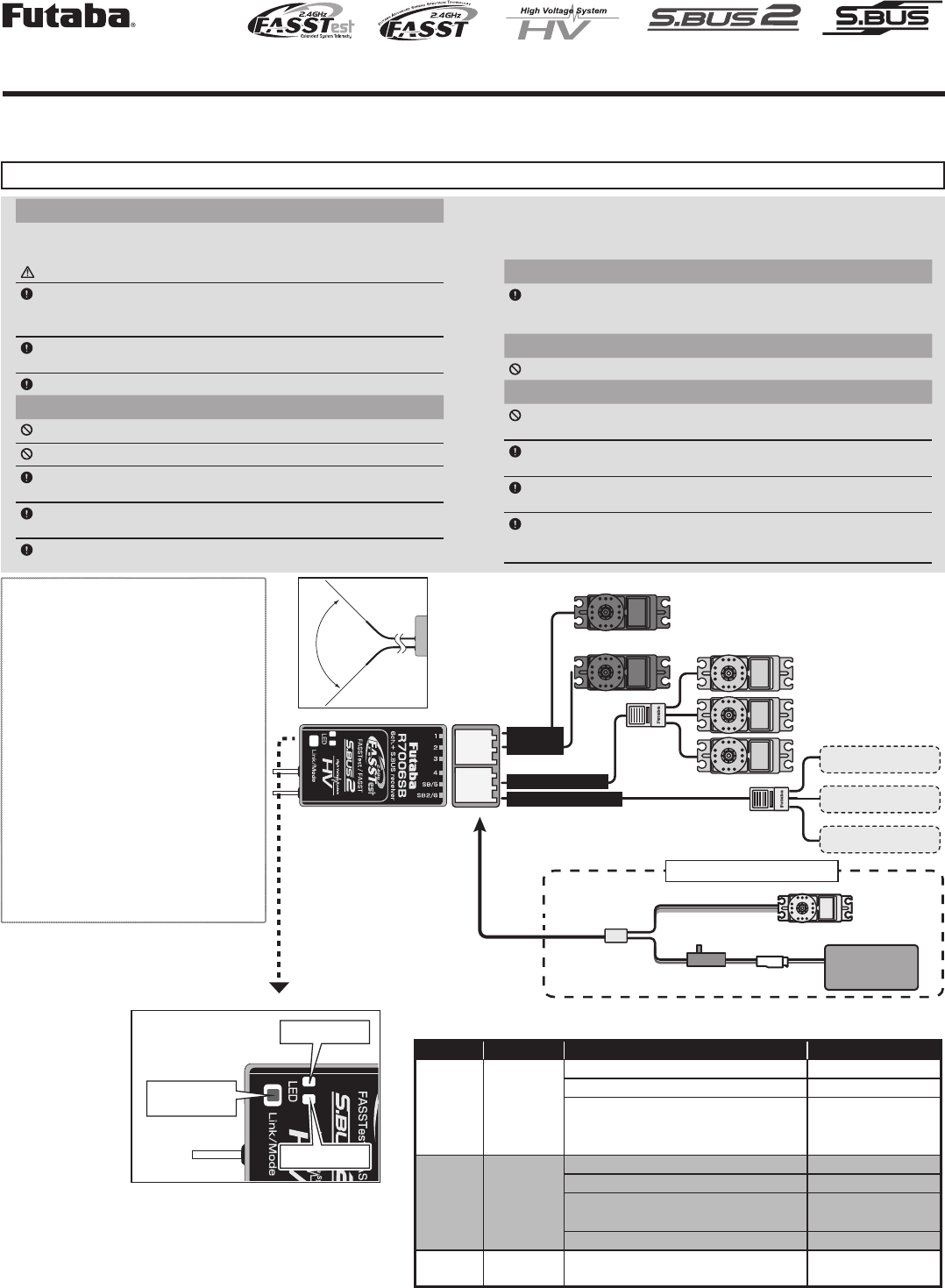
90˚
1M23N31002
LED Indication
R7006SB
S.BUS2 Port (SB2)
S.BUS Port (SB)
Channel
1-6
S.BUS servos
S.BUS Gyros
The receiver power supply can
be connected to any port.
Hub
Hub
S.BUS2equipment
Telemetry sensor
Telemetry sensor
Servo for conventional
system
Battery
3.7 ~ 7.4V
Switch
Servo
Y-harness
When all ports are used.
System Mode LED Status Link LED
FASSTest Green Solid
No signal reception Red Solid
Receiving signals Green Solid
Waiting for link
Start → 2second
later → Red Blink
(1second)
FASST O
No signal reception Red Solid
Receiving signals Green Solid
Receiving signals but ID is
unmatched Green Blink
Waiting for link Red Blink
FASSTest
FASST - Unrecoverable error (EEPROM, etc.) Alternate blink
Link LED
Mode LED
Link/Mode
switch
●Applicable systems: Futaba FASSTest-2.4GHz / FASST (Multi-ch,7ch) -2.4GHz system transmitter
◆FASSTest-2.4GHz Bidirectional Communication System / FASST(Multi-ch,7ch) -2.4GHz
◆S.BUS2 / S.BUS Port and 6 Channels for Conventional System Receiver
Usage precaution
• Analog servos cannot be used with the R7006SB in the FASSTest
12CH / FASST High-speed mode.
WARNING
Changes or modification not especially approved by the party
responsible for compliance could void the user’ s authority to operate the
equipment.
The R7006SB receiver should be protected from vibration by foam
rubber, Velcro, or similar mounting methods. Protect from moisture.
Keep away from conductive materials to avoid short circuits.
Antenna installation precaution
Do not cut or bundle the receiver antenna wire.
Do not bend the coaxial cable. It causes damage.
The antennas must be mounted in such a way to assure they are strain
relieved.
Keep the antenna as far away from the motor, ESC and other noise
sources as you possibly can.
Be sure that the two antennas are placed at 90 degrees to each other.
■The R7006SB has two antennas. In order to maximize signal reception
and promote safe modeling Futaba has adopted a diversity antenna system.
This allows the receiver to obtain RF signals on both antennas and fly
problem-free.
Antenna installation for carbon fuselage
You must leave 30mm at the tip of the antenna fully exposed. The
exposed antenna should be secured so that it cannot move around or
back inside of your aircraft.
Be careful of connector insertion
Don't connect an S.BUS servo / gyro to S.BUS2 connector.
Link precaution
Do not perform the linking procedure while the motor's main power
connected or the engine is operating as it may result in serious injury.
When the linking is complete, please cycle the receiver power and
ensure the receiver is properly linked to the transmitter.
Please power up your system in this order. Transmitter rst, followed
by the receiver.
If the R7006SB receiver was previously linked to another transmitter,
make sure that transmitter is not operating while linking the receiver to
the new transmitter.
Thank you for purchasing a Futaba R7006SB FASSTest-2.4GHz compatible receiver. The R7006SB receiver features bi-directional communication
with a FASSTest Futaba transmitter using the S.BUS2 port. Using the S.BUS2 port an impressive array of telemetry sensors may be utilized. It also
includes both standard PWM output ports (1-6ch) and S.BUS output ports. The R7006SB can also be switched the FASST(Multi-ch/7-ch) System.
Compliance Information Statement
(for U.S.A.)
This device, trade name Futaba Corporation, model
number R7006SB, complies with part15 of the
FCC Rules. Operation is subject to the following
two conditions:
(1) This device may not cause harmful interference,
and
(2) This device must accept any interference
received, including interference that may cause
undesired operation.
(3) This module meets the requirements for a
mobile device that may be used at separation
distances of more than 20cm from human body.
To meet the RF exposure requirements of the FCC
this device shall not be co-located with another
transmitting device.
The responsible party of this device compliance is:
Futaba Service Center
3002 N Apollo Drive Suite 1, Champaign, IL
61822 U.S.A.
TEL (217)398-8970 or E-mail: support@futaba-rc.
com (Support)
Antenna
installation
R7006SB Specications
FASSTest-2.4GHz system(18ch/12ch mode)
FASST-2.4GHz system (Multi-ch/7ch mode)
S.BUS2 and S.BUS port and 6ch for conventional system receiver
• Dual antenna diversity
• Size: 0.89 x 1.5 x 0.48 in. (22.5x38.1x12.2mm)
• Weight: 0.28 oz. (8g)
• Power requirement: 3.7V to 7.4V(Voltage range: 3.5 to 8.4V)
• Battery F/S Voltage: FASSTest---It sets up with a transmitter
FASST---3.8V
*When on "FASST-7ch" mode, the fail safe function can be set for 3-channel only.
*Be sure that when using ESCs regulated output the capacity of the ESC must meet your us-
age condition.
*Never use dry batteries for the power supply of the R7006SB as they may cause difculties.
Green LED
blink System
1 time FASSTest
2 times FASST Multi-ch Normal mode
3 times FASST Multi-ch High-speed mode
4 times FASST 7ch Normal mode
5 times FASST 7ch High-speed mode
R7006SB System table
Output
connector
Channel
Mode A Mode B Mode C Mode D
11119
2 2 2 2 10
3 3 3 3 11
4 4 4 4 12
5/SB 5 S.BUS 6 S.BUS
6/SB2 6 S.BUS2 S.BUS2 S.BUS2
Red LED
blink 1 time 2 times 3 times 4 times
R7006SB CH Mode table
Default
*The telemetry cannot be used with the FASST system.
Channel Modes
The R7006SB is capable of changing its channel allocations as
described in the table below. This is especially important when using
the receiver in a dual receiver mode. See your transmitter operation
manual for complete details on operating in the dual receiver mode.
1 Turn on the receiver. [Transmitter is always OFF]
2 Press and hold the Mode/Link button for 5 seconds to 10
seconds.
3 When the LED of the receiver changes from blinking red to
blinking red with green, Mode/Link button is released.
4 The LED should now be blinking red in 2 times of the patterns
described by the chart below.
5 Each press of the Mode/Link button advances the receiver to
the next mode.
6 When you reach the mode that you wish to operate in, press
and hold the Mode/Link button for more than 2 seconds.
When LED blinks in green with red, it is the completion of a
mode change, Mode/Link button is released.
7 Please cycle the receiver power off and back on again after
changing the Channel mode.
Systems (FASSTest ⇔FASST) change method
1 Turn on the receiver. [Transmitter is always OFF]
2 Press and hold the Link/Mode button for more then 10
seconds.
3 When the LED begins to blink green the button may be
released.
4 The LED should now be blinking green in one of the patterns
described by the chart below.
( Default : FASSTest )
5 Each press of the Mode/Link button advances the receiver to
the next system.
6 When you reach the system that you wish to operate in, press
and hold the Mode/Link button for more than 2 seconds.
When LED blinks in green with red, it is the completion of a
system change, Mode/Link button is released.
7 Please cycle the receiver power off and back on again after
changing the system.
Default
FASSTest is a bidirectional communication system between the
R7006SB receiver and FASSTest capable transmitters. Multiple
optional telemetry sensors may be connected to the S.BUS2 on the
receiver and that data is in turn displayed on the transmitter.
Link to the transmitter : FASSTest
1 Bring the transmitter and the receiver close to each other,
within 20 inches (half meter).
2 Turn on the transmitter. Place the transmitter into the receiver
linking mode.
3 Turn on the receiver.
4 The receiver will wait for the linking process to begin for 2
seconds. Following that it will return to the normal operation
mode.
5 When the LED of the receiver changes from blinking red to
solid green, linking is complete.
(A link waiting state is ended in 1 second.)
• Refer to the transmitters operation manual for complete details on how
to place the transmitter into the linking mode.
• If there are many FASSTest systems turned on in close proximity, your
receiver might have difficulty establishing a link to your transmitter.
This is a rare occurrence. However, should another FASSTest
transmitter/receiver be linking at the same time, your receiver could link
to the wrong transmitter. This is very dangerous if you do not notice
this situation. In order to avoid the problem,we strongly recommend
you to double check whether your receiver is really under control by
your transmitter.
• If the System Type of the transmitter is changed, the receiver will need
to be re-linked to the transmitter.
Link to the TMA-1 Telemetry Adapter
1 R7006SB has to be FASSTest.
2 First, a transmitter and a receiver are linked.
3 Transmitter is turned off.
4 Press and hold the Mode/Link button of R7006SB for 15 seconds.
5 When LED of R7006SB, Red Blink → Red with green Blink → Green Blink →
Red Blink → Mode/Link button is released.
6 R7006SB was link mode with TMA-1. The LED blinks in green with red of
R7006SB.
7 The link button of TMA-1 is pushed for a long time to LED blink.
8 Completion of a link will change LED of TMA-1 green from red only for a
moment.
9 Please cycle the receiver power.
S.BUS2
S.BUS2 extends S.BUS and supports bidirectional communication.
Sensors are connected to the S.BUS2 port.
Link to the transmitter : FASST
1 Bring the transmitter and the receiver close to each other,
within 20 inches (half meter).
2 Turn on the transmitter and receiver.
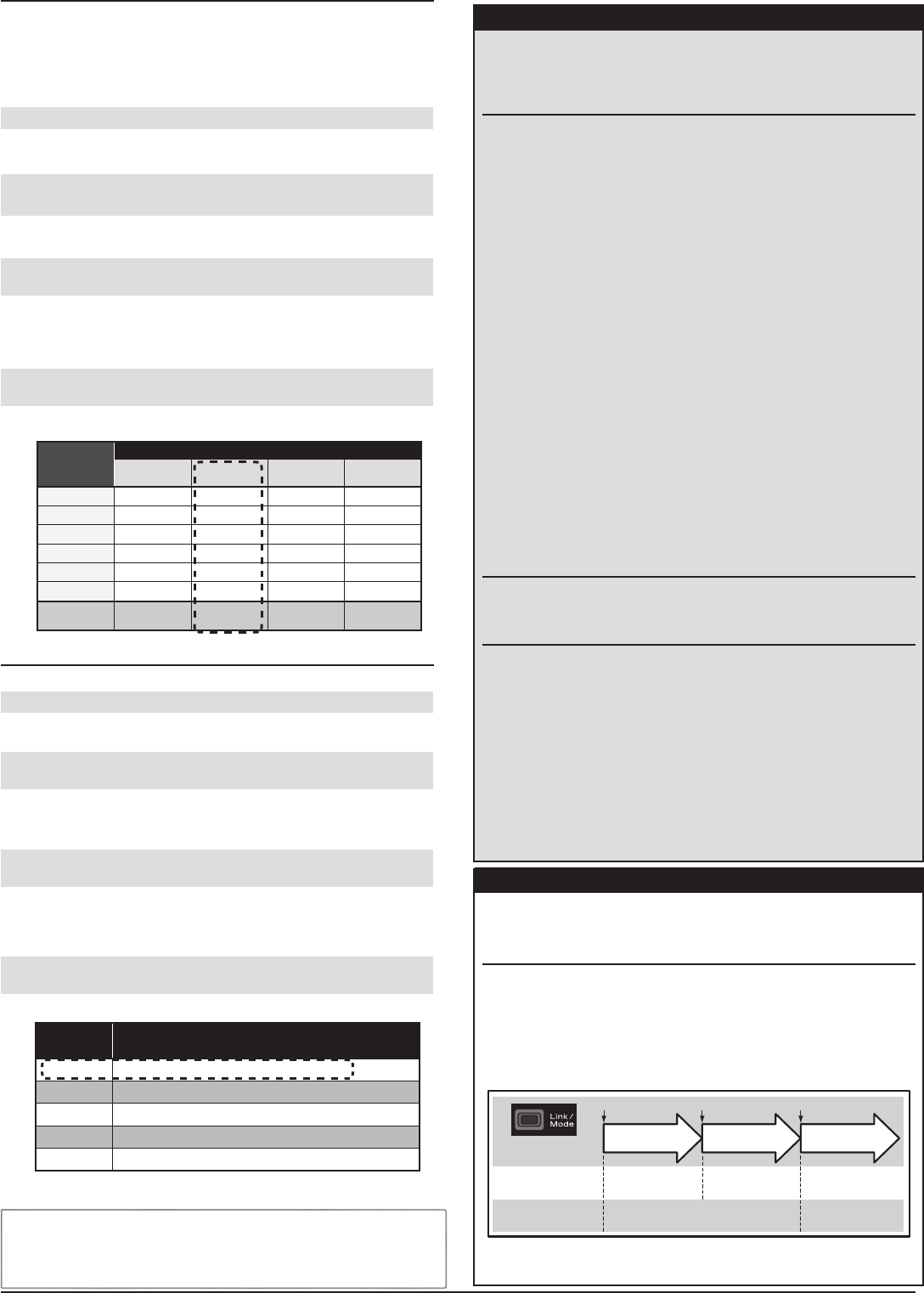
3 Link operation is performed by the Link/Mode switch.
• When using TM-8 module, it's possible to set F/S position (only 3CH).
0 to 1 sec. 1 to 2 sec. More than 2 sec.
0 sec. 1 sec. 2 sec.
Press and Hold time
No function
With TM-8
(not included in this set)
To set the F/S
position(No re-link)
Re-link(ID set) and to
set the F/S position
No function
Besides TM-8 Re-link(ID set)
*Refer to the instruction manual of the transmitter or module used for a description
of the linking operation, F/S position setting methods and other details.
When switched, the R7006SB can use the FASST-Multi/7ch mode. When the
FASST system is used, the telemetry cannot be used. The FASST system has
a Normal mode and a High-speed mode. However, in the High-speed mode,
analog servos cannot be used.
FASSTest
FASST
FUTABA CORPORATION
1080 Yabutsuka, Chosei-mura, Chosei-gun, Chiba-ken, 299-4395, Japan
Phone: +81 475 32 6982, Facsimile: +81 475 32 6983
©FUTABA CORPORATION 2015, 11 (1)
本產品符合低功率電波輻射性電機管理辦法 第十二條、第十四條等條文規定
1. 經型式認證合格之低功率射頻電機,非經許可,公司、商號或使用者均不得擅自變更頻率、加
大功率或變更原設計之特性及功能。
2. 低功率射頻電機之使用不得影響飛航安全及干擾合法通信;經發現有干擾現象時,應立即停用,
並改善至無干擾時方得繼續使用。前項合法通信,指依電信法規定作業之無線電通信。低功率
射頻電機須忍受合法通信或工業、科學及醫療用電波輻射性電機設備之干擾。