Futaba T10CG-24G Radio Control(Transmitter) User Manual 10CG ENG 1M23N21005
Futaba Corporation Radio Control(Transmitter) 10CG ENG 1M23N21005
UserManual.wiki
>
Futaba
>
T10CG 24G User Manual
User manual
Navigation menu
Upload a User Manual
Namespaces
Wiki Guide
HTML
PDF
Info
Views
User Manual
Discussion / Help
Navigation
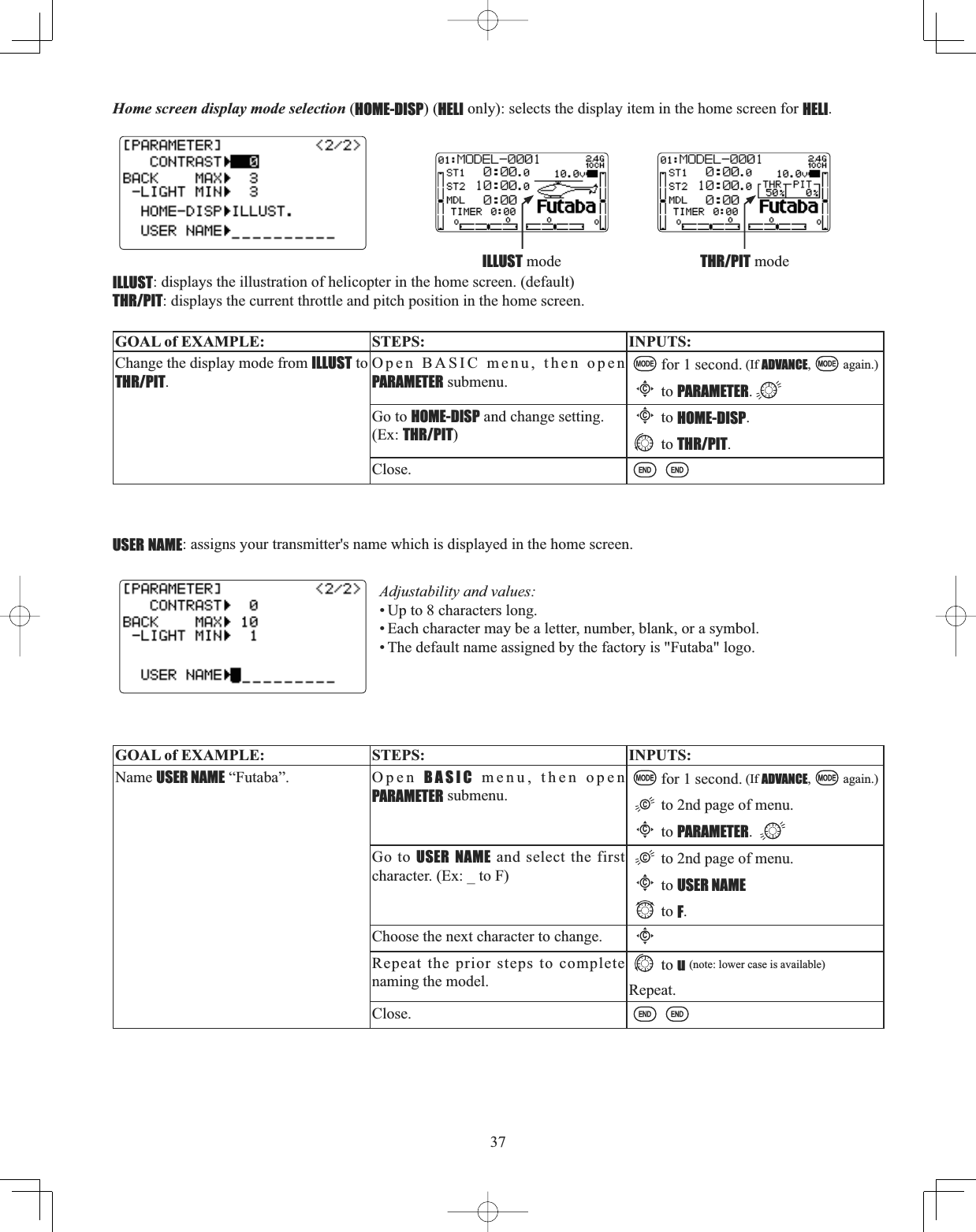
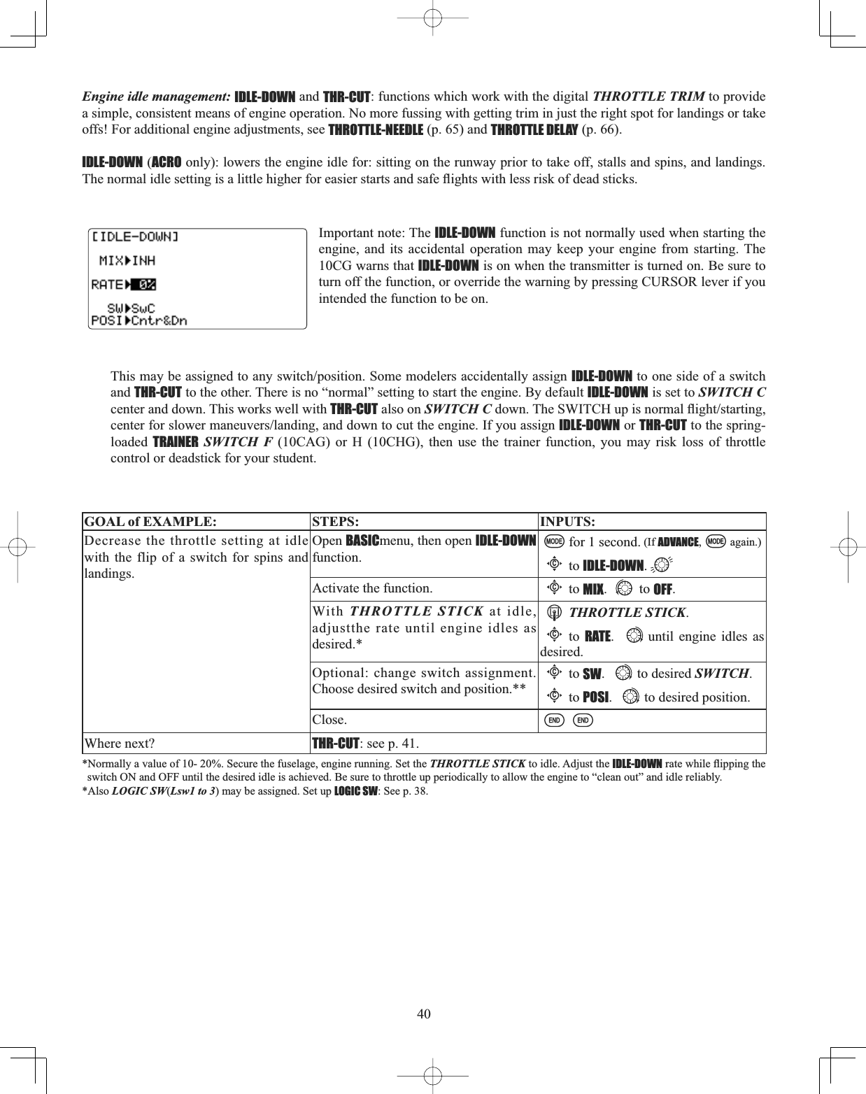
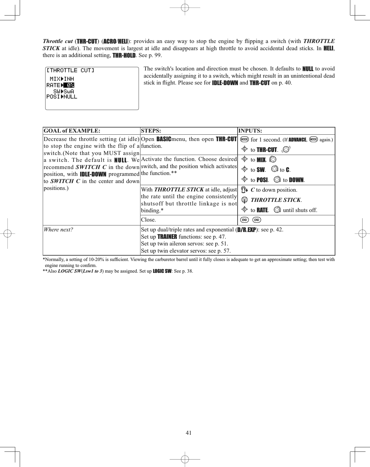
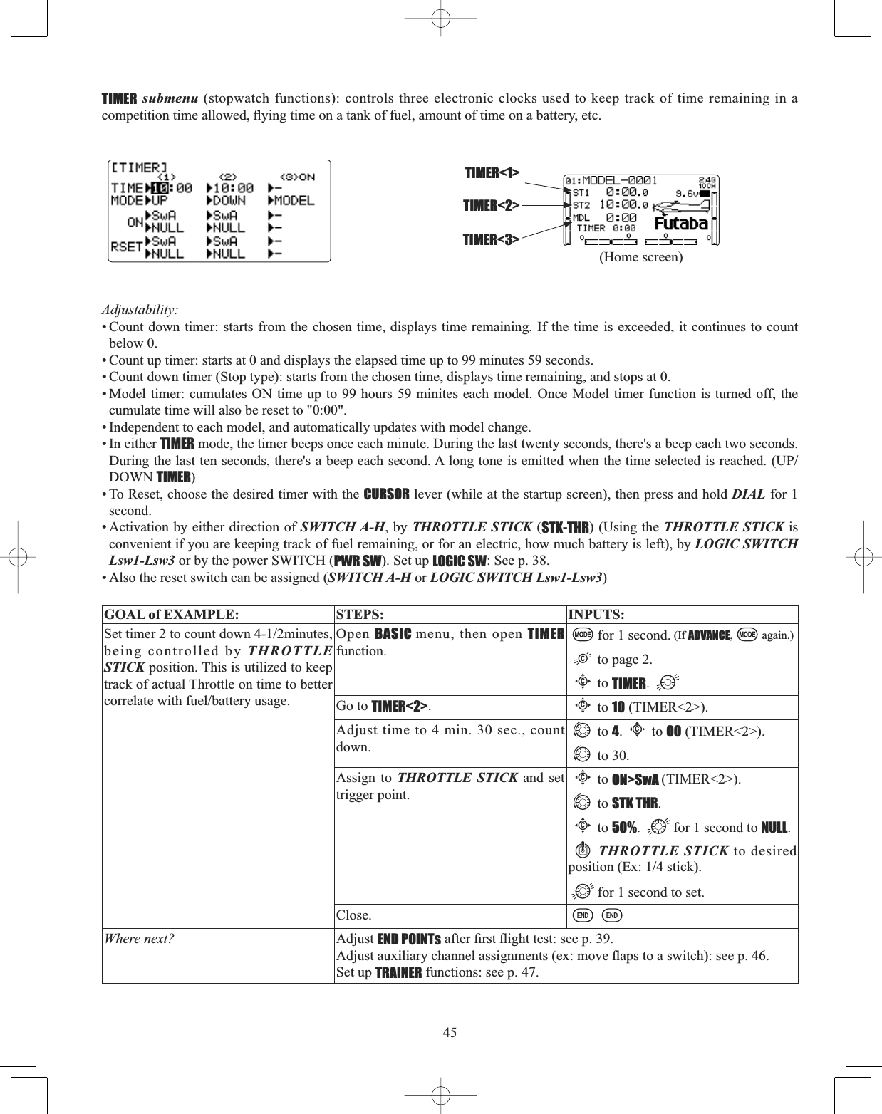
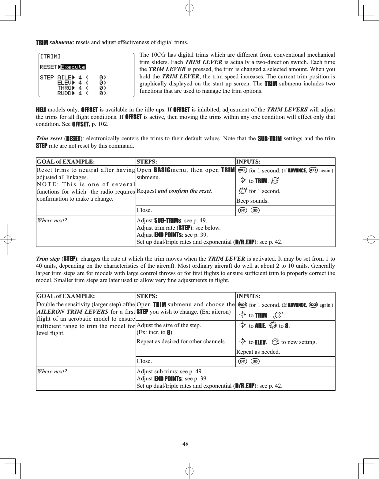
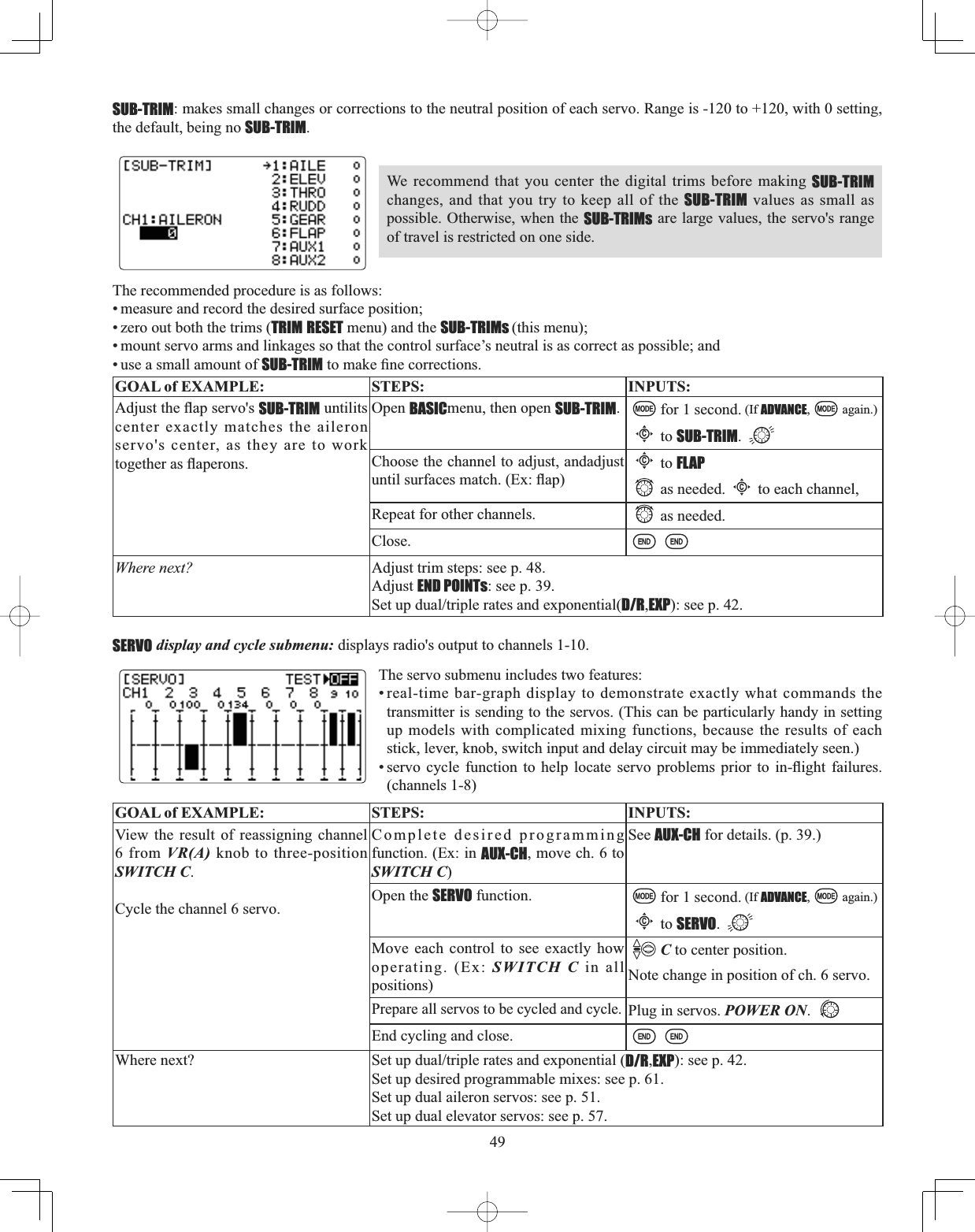
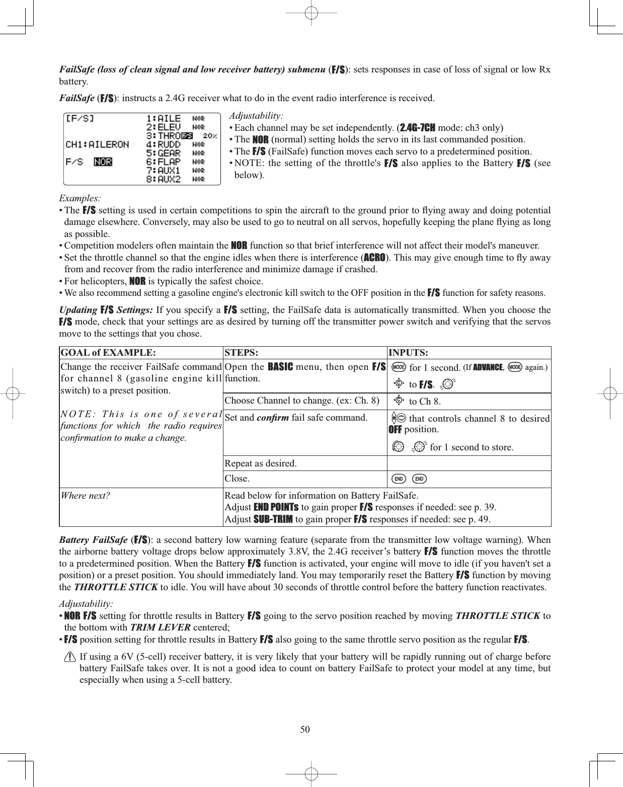
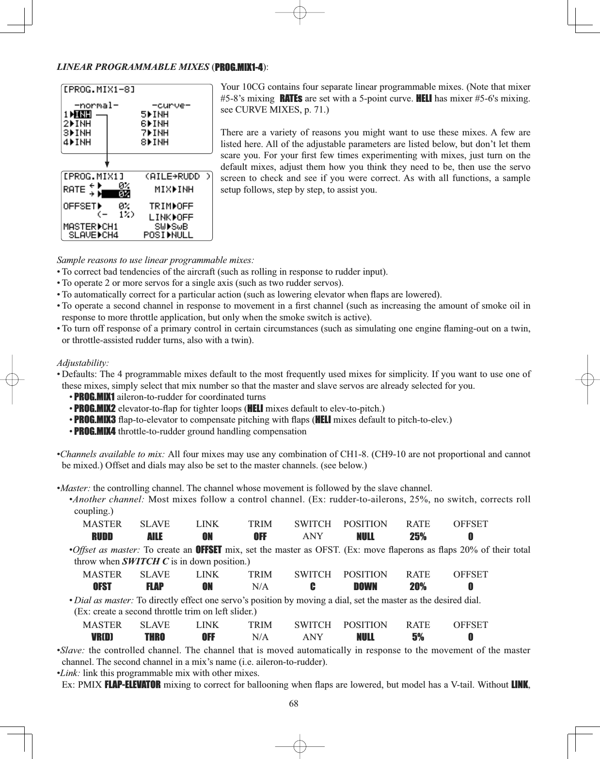
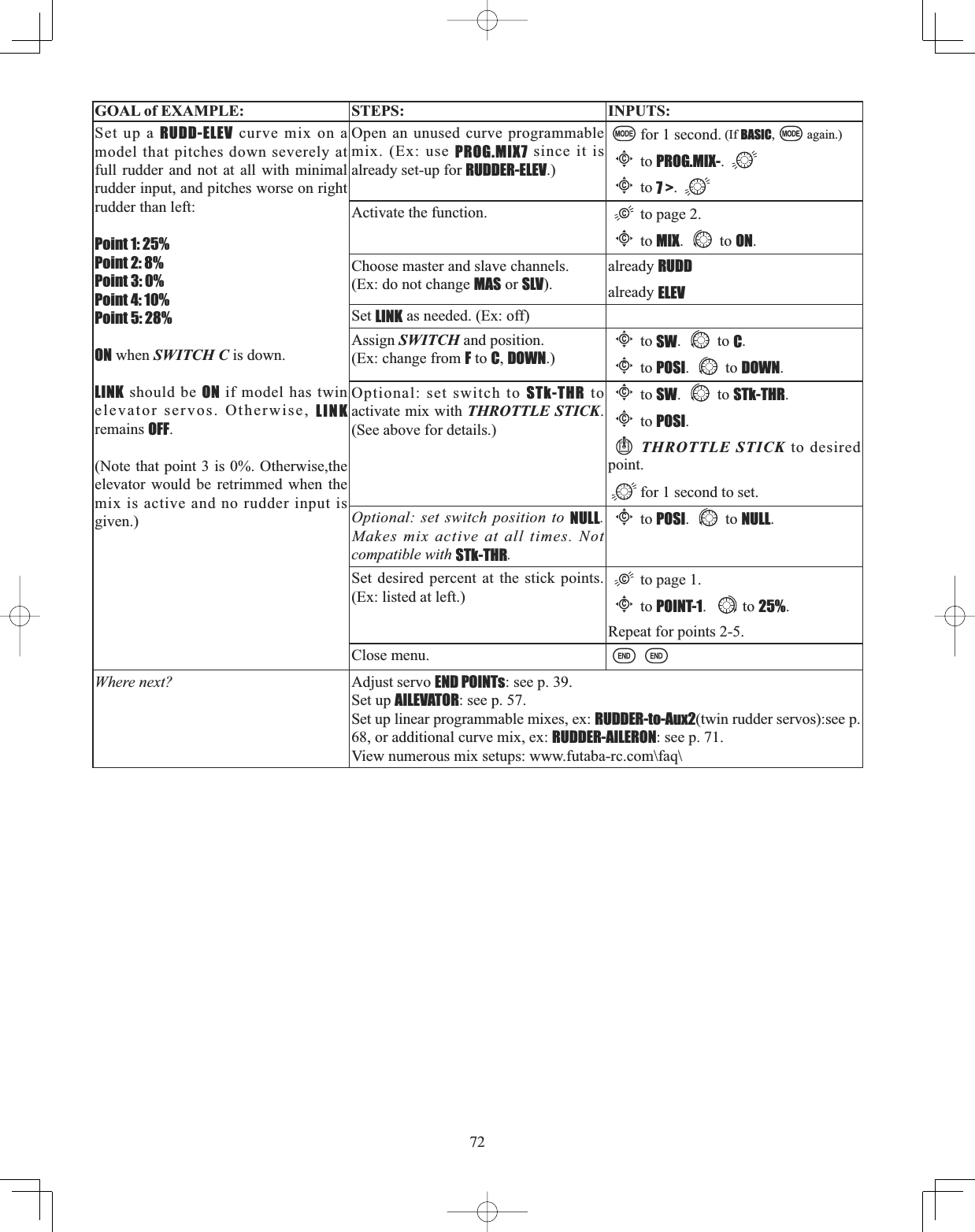
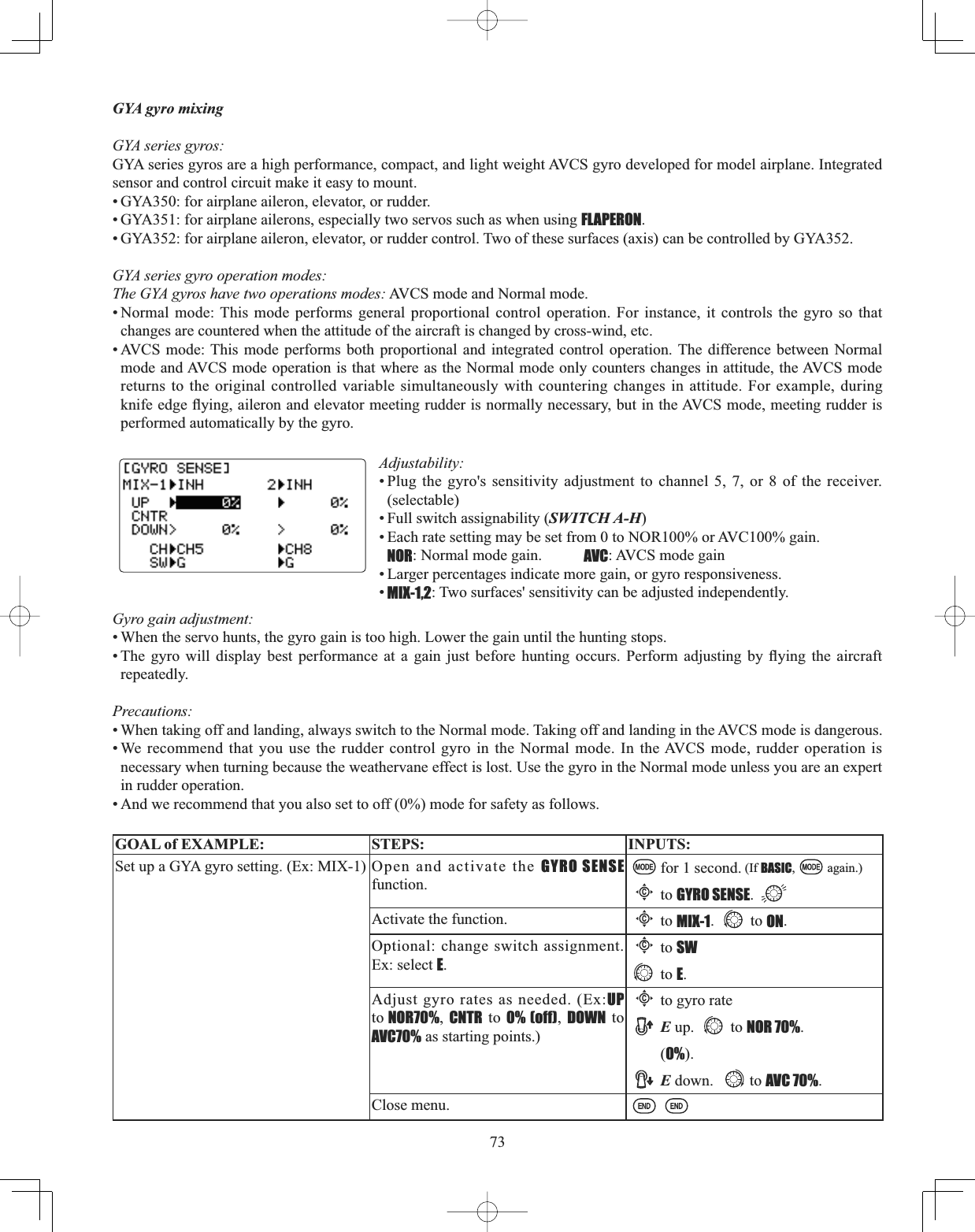
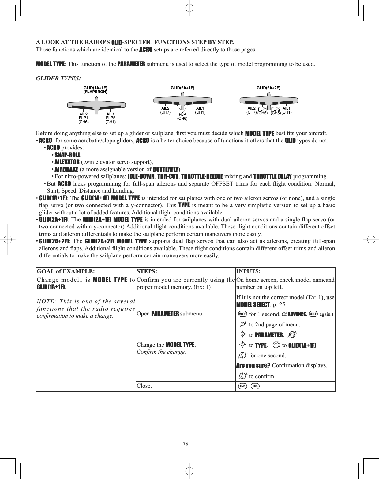
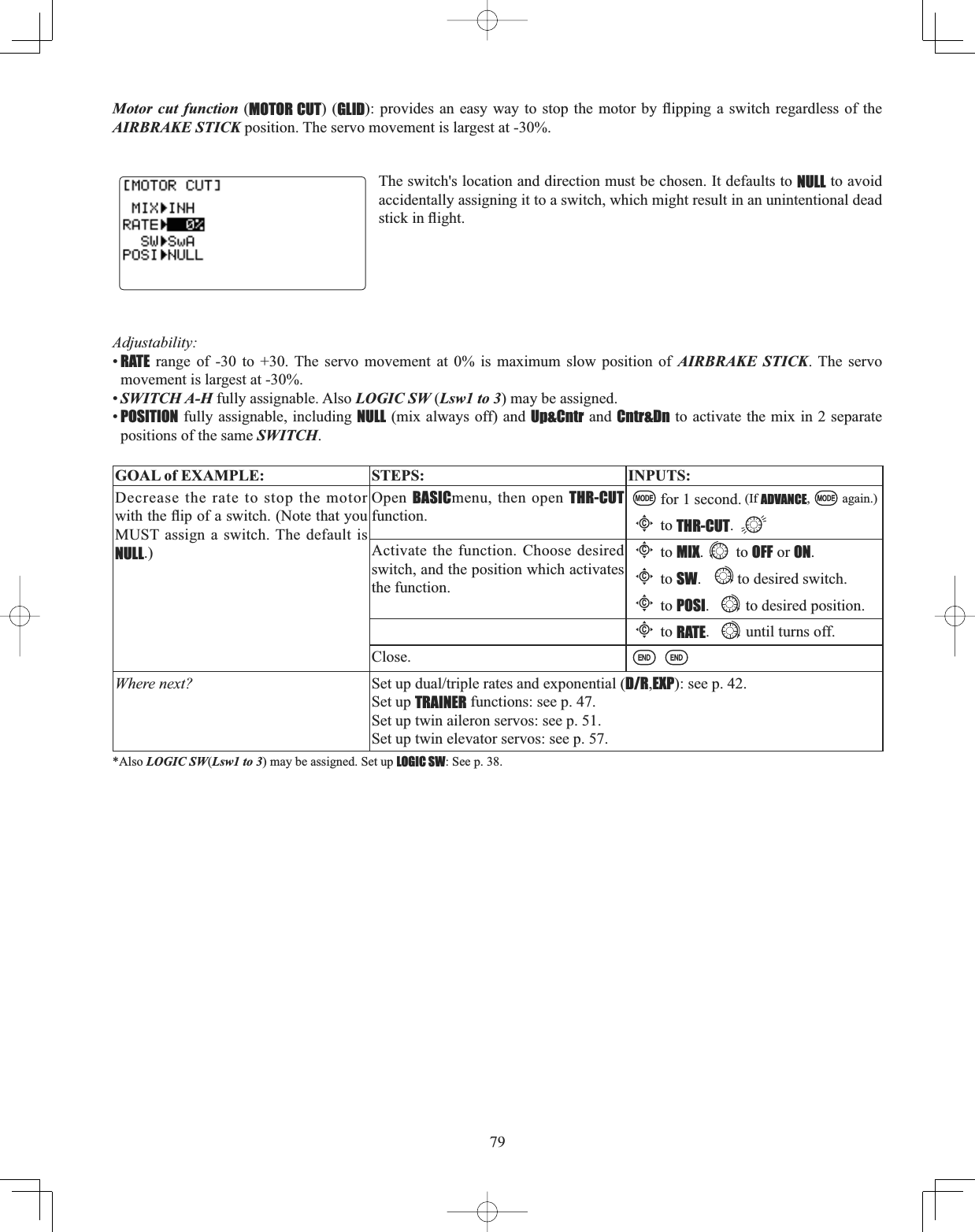
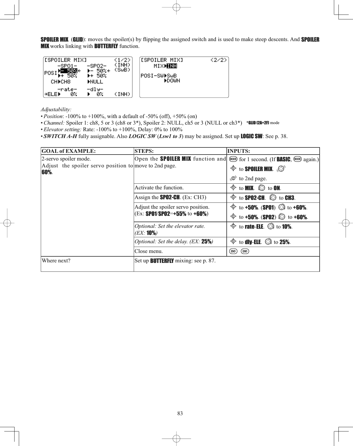
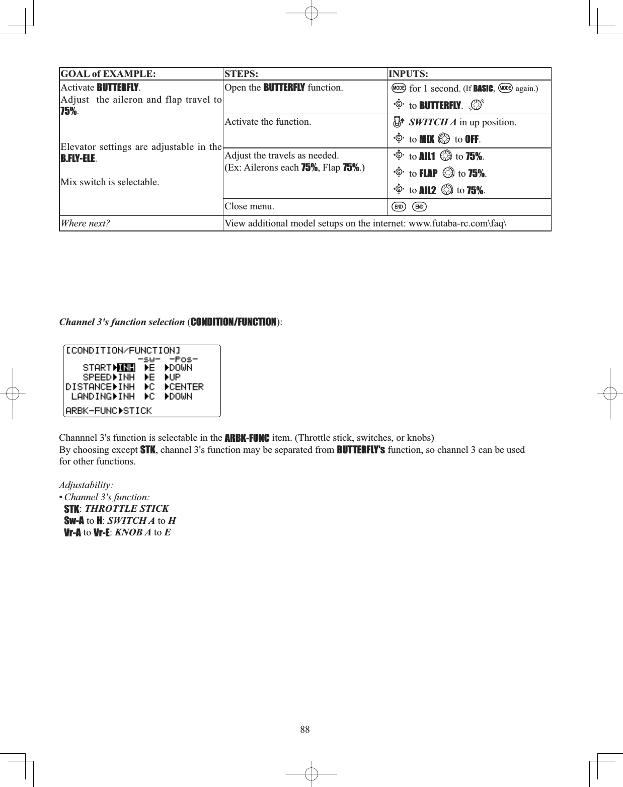
![2TABLE OF CONTENTSINTRODUCTION ........................................................... 3Additional Technical Help, Support and Service ........ 3$SSOLFDWLRQ([SRUWDQG0RGL¿FDWLRQ ........................ 4Meaning of Special Markings ..................................... 5Safety Precautions (do not operate without reading) .. 5 Introduction to the 10CG ............................................ 7&RQWHQWVDQG7HFKQLFDO6SHFL¿FDWLRQV........................ 9Accessories ............................................................... 10Transmitter Controls & 6ZLWFK,GHQWL¿FDWLRQ$VVLJQPHQWV ............................. 11Charging the Ni-Cd Batteries ................................... 15Stick Adjustments ..................................................... 16Adjusting display contrast ........................................ 16Changing mode.......................................................... 17Power Down mode .................................................... 17CAMPacLQLWLDOL]LQJDQGGDWDFRQYHUVLRQ&&6WR&*.... 17Radio Installation & Range Checking ...................... 18Transmitter Displays and Buttons ............................. 23Warning and Error Displays ..................................... 24AIRPLANE (ACRO) FUNCTIONS ................................ 25Map of Functions........................................................ 26Quick Guide to Setting up a 4-channel Airplane ...... 27ACRO BASIC MENU FUNCTIONS ................................ 30MODEL Submenu: MODEL SELECT,COPY,NAME .......... 30 PARAMETER Submenu: RESET,TYPE,MODUL,ATL,AILE-2,THR-REV,CONTRAST,BACK-LIGHT,HOME-DISP,USER NAME........ 33LOGIC SW..................................................................... 38Servo REVERSE ........................................................... 38END POINT .................................................................. 39Idle Management: IDLE DOWN and THR-CUT .............. 40'XDO7ULSOH5DWHVDQG([SRQHQWLDOD/R,EXP) .......... 42TIMER Submenu.......................................................... 45Auxiliary Channel assignments and CH9 reverse (AUX-CH). 46TRAINER ..................................................................... 47TRIM and SUB-TRIM ................................................... 48SERVO Display ........................................................... 49Fail Safe and Battery FailSafe (F/S) ......................... 50ACRO ADVANCE MENU FUNCTIONS ........................... 51Wing types ................................................................ 51FLAPERON ................................................................... 52FLAP TRIM .................................................................. 53Aileron Differential (AILE-DIFF) ................................. 54Using Twin Aileron Servos: AILE-2 ........................... 55ELEVON (see tail types) ............................................... 56Tail types ................................................................... 56ELEVON ....................................................................... 56Twin Elevator Servos (AILEVATOR) ............................ 57V-TAIL ......................................................................... 58SNAP ROLL .................................................................. 590L[HVGH¿QLWLRQVDQGW\SHV ..................................... 61ELEV-FLAP .................................................................... 62AIRBRAKEBUTTERFLY (crow) ..................................... 63THROTTLE-NEEDLE ........................................................ 65THROTTLE DELAY ......................................................... 66THROTTLE CURVE ........................................................ 67Linear, Prog. mixes 1-4 ............................................. 68Curve, Prog. mixes 5-8 ............................................. 71GYA gyro mixing (GYRO SENSE) ............................... 73Other Equipment ....................................................... 74GLIDER (GLID(1A+1F)(2A+1F)(2A+2F)) FUNCTIONS . 75 Table of contents........................................................ 75 Getting Started with a Basic 4-CH Glider ................ 76 GLIDER-SPECIFIC BASIC MENU FUNCTIONS ........ 78 Model type (PARAMETER submenu) ........................... 78MOTOR CUT ................................................................ 79 GLIDER-SPECIFIC ADVANCE MENU FUNCTIONS..... 80 AILE/RUDD .................................................................. 81AILE-FLAP (GLID(2A+2F) only) .................................... 82SPOILER MIX ............................................................... 83OFFSETs$GGLWLRQDOÀLJKWFRQGLWLRQV...................... 84START DELAY (GLID(1A+1F) only) ................................. 85 CAMBER MIX ............................................................... 85CAMBER FLAP .............................................................. 86BUTTERFLY................................................................... 87 Channel 3’s function selection (CONDITION/FUNCTION) 88 HELICOPTER FUNCTIONS.......................................... 89Table of contents and reference info for helicopters . 89Getting Started with a Basic Helicopter ................... 90HELI-SPECIFIC BASIC MENU FUNCTIONS ................ 93MODEL TYPE (PARAMETERS submenu) ........................ 93SWASH AFR (swashplate surface direction and travelcorrection) (not in H-1) .............................................. 95Setting up the Normal Flight Condition ................... 97THR-CUTVSHFLDOL]HGVHWWLQJVIRUKHOLFRSWHUVSHFL¿Fmodels) ..................................................................... 98HELI-SPECIFIC ADVANCE MENU FUNCTIONS ........... 99THROTTLE HOLD .......................................................... 99THR-CURVE,PIT-CURVE and REVO ............................. 100Idle-ups ................................................................... 1017ULPVRIIVHW............................................................. 102Delay ....................................................................... 103Hovering setups ...................................................... 104+LJKORZSLWFK ........................................................ 105Gyros and governors ............................................... 106THROTTLE MIX ............................................................ 96SWASH RING .............................................................. 96Glossary ........................................................................ 110Note that in the text of this manual, beginning at this point, any time we are using a feature’s specialized name or abbreviation, as seen on the screen of the 10C, that name, feature, or abbreviation will be exactly as seen on the radio’s screen, including capitalization and shown in aDIFFERENT TYPE STYLE for clarity. Any time we mention a specific control on the radio itself, such as moving SWITCH A,KNOB VR(B), or the THROTTLE STICK,those words will be displayed as they are here.](https://usermanual.wiki/Futaba/T10CG-24G/User-Guide-1093539-Page-2.png)
![4$SSOLFDWLRQ([SRUWDQG0RGL¿FDWLRQ1. This product may be used for model airplane or surface (boat, car, robot) use. It is not intended for use in any application other than the control of models for hobby and recreational purposes. The product is subject to regulations of the Ministry RI5DGLR7HOHFRPPXQLFDWLRQVDQGLVUHVWULFWHGXQGHU-DSDQHVHODZWRVXFKSXUSRVHV2. Exportation precautions: (a) When this product is exported from the country of manufacture, its use is to be approved by the laws governing the country of destination which govern devices that emit radio frequencies. If this product is then re-exported to other countries, it may be subject to restrictions on such export. Prior approval of the appropriate government authorities may be required. If you have purchased this product from an exporter outside your country, and not the authorized Futaba distributor in your country, please contact the seller immediately to determine if such export regulations have been met. (b) Use of this product with other than models may be restricted by Export and Trade Control Regulations, and an application for export approval must be submitted. This equipment must not be utilized to operate equipment other than radio controlled models. 0RGL¿FDWLRQDGMXVWPHQWDQGUHSODFHPHQWRISDUWV)XWDEDLVQRWUHVSRQVLEOHIRUXQDXWKRUL]HGPRGL¿FDWLRQDGMXVWPHQWand replacement of parts on this product. Any such changes may void the warranty. Compliance Information Statement (for U.S.A.)7KLVGHYLFHWUDGHQDPH)XWDED&RUSRUDWLRQRI$PHULFDPRGHOQXPEHU5+65+6FRPSOLHVZLWKSDUWRIWKHFCC Rules. Operation is subject to the following two conditions:(1) This device may not cause harmful interference, and(2) This device must accept any interference received, including interference that may cause undesiredoperation.The responsible party of this device compliance is:Futaba Service Center3002 N Apollo Drive Suite 1, Champaign, IL 61822 U.S.A.TEL (217)398-8970 or E-mail: support@futaba-rc.com (Support)TEL (217)398-0007 or E-mail: service@futaba-rc.com (Service) The RBRC. SEAL on the nickel-cadmium battery contained in Futaba products indicates that Futaba Corporation of America is voluntarily participating in an industry-wide program to collect and recycle these batteries at the end of their useful lives, when taken out of service within the United States. The RBRC. program provides a convenient alternative to placing used nickel-cadmium batteries into the trash or municipal waste system, which is illegal in some areas. (for USA) You may contact your local recycling center for information on where to return the spent battery. Please call 1-800-8BATTERY for information on Ni-Cd battery recycling in your area. Futaba Corporation of America’s involvement in this program is part of its commitment to protecting our environment and conserving natural resources. *RBRC is a trademark of the Rechargeable Battery Recycling Corporation.](https://usermanual.wiki/Futaba/T10CG-24G/User-Guide-1093539-Page-4.png)
![5Meaning of Special Markings Pay special attention to safety where indicated by the following marks: DANGER3URFHGXUHVZKLFKPD\OHDGWRGDQJHURXVFRQGLWLRQVDQGFDXVHGHDWKVHULRXVLQMXU\LIQRWFDUULHGRXWproperly. WARNING - Procedures which may lead to a dangerous condition or cause death or serious injury to the user if QRWFDUULHGRXWSURSHUO\RUSURFHGXUHVZKHUHWKHSUREDELOLW\RIVXSHU¿FLDOLQMXU\RUSK\VLFDOGDPDJHLVKLJKCAUTION - Procedures where the possibility of serious injury to the user is small, but there is a danger of injury, or physical damage, if not carried out properly. = Prohibited = Mandatory Warning: Always keep electrical components away from small children. FLYING SAFETY WARNINGTo ensure the safety of yourself and others, please observe the following precautions: Have regular maintenance performed. Although your 10CG protects the model memories with non-volatile EEPROM memory (which does not require periodic replacement) and not a battery, it still should have regular checkups for wear and tear. We recommend sending your system to the Futaba Service Center annually during \RXUQRQÀ\LQJVHDVRQIRUDFRPSOHWHFKHFNXSDQGVHUYLFHNi-Cd Battery Charge the batteries! (See Charging the Ni-Cd batteries, p. 15, for details.) Always recharge the transmitter and UHFHLYHUEDWWHULHVIRUDWOHDVWKRXUVEHIRUHHDFKÀ\LQJVHVVLRQ$ORZEDWWHU\ZLOOVRRQGLHFDXVLQJORVVRIFRQWURODQG D FUDVK :KHQ \RX EHJLQ \RXU À\LQJ VHVVLRQ UHVHW \RXU &*¶V EXLOWLQ WLPHU DQG GXULQJ WKH VHVVLRQ SD\attention to the duration of usage. Stop flying long before your batteries become low on charge. Do not rely on your radio’s low battery warning systems, intended only as a precaution, to tell you when to recharge. Always check your transmitter DQGUHFHLYHUEDWWHULHVSULRUWRHDFKÀLJKWWhere to Fly :HUHFRPPHQGWKDW\RXÀ\DWDUHFRJQL]HGPRGHODLUSODQHÀ\LQJ¿HOG<RXFDQ¿QGPRGHOFOXEVDQG¿HOGVE\DVNLQJyour nearest hobby dealer, or in the US by contacting the Academy of Model Aeronautics. You can also contact the national Academy of Model Aeronautics (AMA), which has more than 2,500 chartered clubs across the country. Through any one of them, instructor training programs and insured newcomer training are available. Contact the AMA at the address or toll-free phone number below. Academy of Model Aeronautics 5161 East Memorial DriveMuncie, IN 47302-9252Tele. (800) 435-9262Fax (765) 741-0057or via the Internet at http:\\www.modelaircraft.org $OZD\VSD\SDUWLFXODUDWWHQWLRQWRWKHÀ\LQJ¿HOG¶VUXOHV as well as the presence and location of spectators, the ZLQGGLUHFWLRQDQGDQ\REVWDFOHVRQWKH¿HOG%HYHU\FDUHIXOÀ\LQJLQDUHDVQHDUSRZHUOLQHVWDOOEXLOGLQJVRUcommunication facilities as there may be radio interference in their vicinity. ,I\RXPXVWÀ\DZD\IURPDFOXE¿HOGEHVXUHWKHUHDUHQRRWKHUPRGHOHUVÀ\LQJZLWKLQDWKUHHWR¿YHPLOHUDQJH, or you may lose control of your aircraft or cause someone else to lose control.](https://usermanual.wiki/Futaba/T10CG-24G/User-Guide-1093539-Page-5.png)
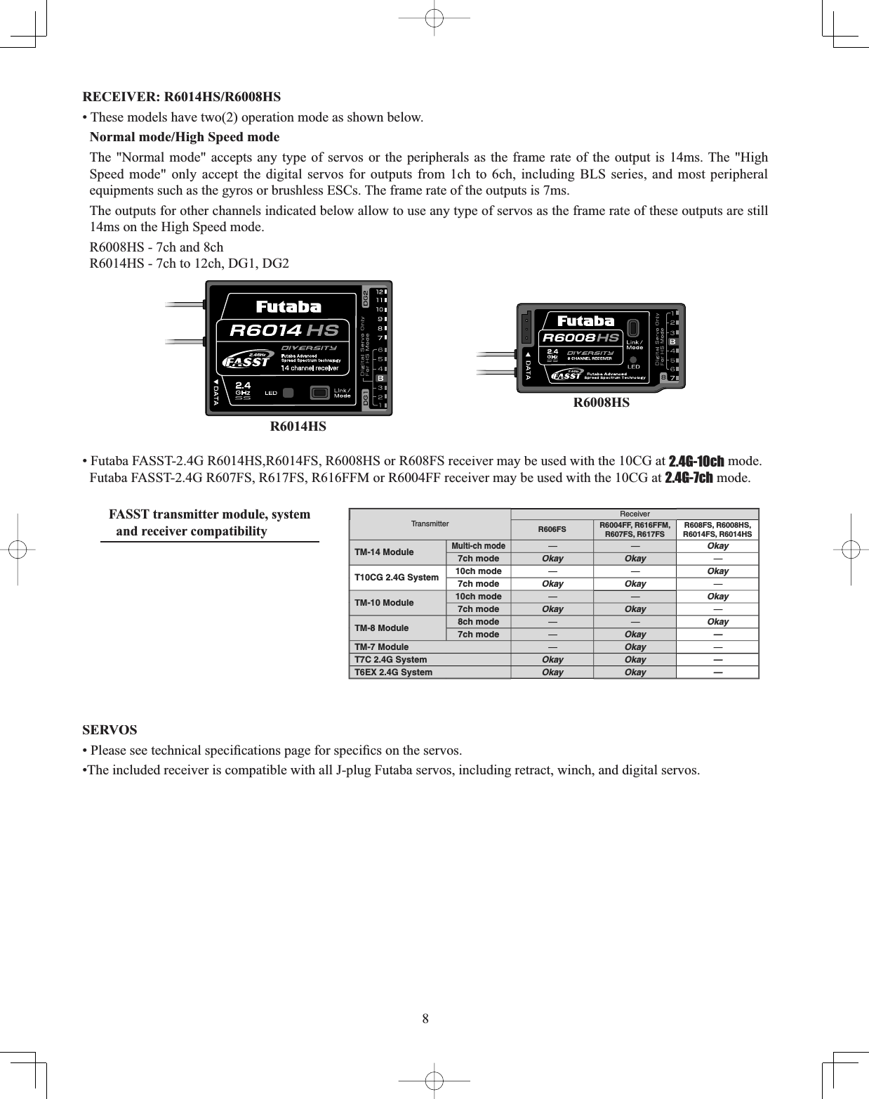
![9CONTENTS AND TECHNICAL SPECIFICATIONS 6SHFL¿FDWLRQVDQGUDWLQJVDUHVXEMHFWWRFKDQJHZLWKRXWQRWLFHYour 10CAG, 10CHG or 10CG (packaged with an 8 or a 14-channel FASST-2.4G receiver) system includes the following components: •T10CAG, T10CHG or T10CG Transmitter •R6008HS or R6014HS Receiver • N55%&+*RQO\RU15-&$*RQO\1L&GEDWWHU\& Charger• Switch harness • Aileron extension cord• Neck strap* The set contents depend on the type of set.Transmitter T10CAG/HG/G (2-stick, 10-channel, FASST-2.4G system) Transmitting frequency: 2.4GHz bandModulation: 2.4G-7ch or 2.4G-10ch, switchable Power supply: 9.6V NT8S700B Ni-Cd battery Receiver R6008HS/R6014HS(Dual antenna diversity)Power requirement: 4.8V or 6.0V battery or regulated output from ESC, etc. (*1)6L]H5+6[ [LQ [[PPR6014HS: 2.06 x 1.48 x 0.63 in. (52.3 x 37.5 x 16.0 mm):HLJKW5+6R]J5+6R]J(*1) Be sure that when using ESC's regulated output the capacity of the ESC must meet your usage condition.Usage condition on "High Speed mode" (R6008HS/R6014HS) CAUTION Outputs from 1ch to 6ch accept the digital servos only or most type of peripherals.If any analog servos connected to these output as it will cause malfunction. Please check the peripherals if there's any malfunction with whole stick lever throw. If any malfunction occur please change the operation mode to "Normal mode."Output of other channels shown below allow to use any type of servos.R6008HS - 7ch and 8chR6014HS - 7ch to 12ch, DG1, DG2(For Operation Mode Selection, see p.20)(Suggested Servo for use with your 10CG system)Servo S9252 (Digital servo) Control system: Pulse width control, 1.52 ms neutralPower requirement: 4.8 V (from receiver)Output torque: 91.7 oz.-in. (6.6 kg-cm) at 4.8V2SHUDWLQJVSHHGVHFDW9Size: 1.57 x 0.79 x 1.44 in. (40 x 20 x 36.6 mm)Weight: 1.76 oz. (50 g)Servo S9255 (Digital servo) Control system: Pulse width control, 1.52 ms neutralPower requirement: 4.8 V (from receiver)Output torque: 125.0 oz.-in. (9.0 kg-cm) at 4.8V2SHUDWLQJVSHHGVHFDW9Size: 1.57 x 0.79 x 1.44 in. (40 x 20 x 36.6 mm)Weight: 1.94 oz. (55 g)Servo S3151 (Standard, Digital servo) Control system: Pulse width control, 1.52 ms neutralPower requirement: 4.8 V (from receiver)Output torque: 43.1 oz.-in. (3.1 kg-cm) at 4.8V2SHUDWLQJVSHHGVHFDW9Size: 1.59 x 0.79 x 1.42 in. (40.5 x 20 x 36.1 mm)Weight: 1.48 oz. (42 g)Servo S3001 (Standard, ball-bearing) Control system: Pulse width control, 1.52 ms neutralPower requirement: 4.8 - 6.0V (from receiver)Output torque: 41.7 oz.-in. (3.0 kg-cm)2SHUDWLQJVSHHGVHFSize: 1.59 x 0.78 x 1.41 in. (40.4 x 19.8 x 36 mm)Weight: 1.59 oz. (45.1g)](https://usermanual.wiki/Futaba/T10CG-24G/User-Guide-1093539-Page-9.png)
![19Fasten about 5-10cm from the servo outlet so that the lead wire is neat.Margin in the lead wire.• To prevent the servo lead wires from being broken by vibration during ÀLJKWSURYLGHDPDUJLQVRWKDWWKHZLUHVWLFNVRXWVOLJKWO\DQGIDVWHQLWat suitable points. In addition, periodically check the wire during daily maintenance.IMPORTANT: Since the 2.4GHz have different characteristics than that of the conventional 27MHz and 72MHz IUHTXHQFLHVSOHDVHUHDGWKLVVHFWLRQFDUHIXOO\WRHQMR\VDIHÀLJKWZLWKWKH*+]V\VWHP5HFHLYHUV$QWHQQD,QVWDOODWLRQAntenna*Must be kept as straight as possible.Coaxial cableR6014HS Receiver7KH5+65+6KDVWZRDQWHQQDV7KHVHDQWHQQDVKDYHa diversity function to decrease the chance of a receiving error. • Since the wavelength of the 2.4GHz is much shorter than that of the conventional frequencies 27MHz and 72MHz, it is very susceptible to loss of signal which results in a receiving error. ,Q RUGHUWRDYRLGWKLVSKHQRPHQRQWKH5+65)6adopted a diversity antenna system. • To obtain the best results of the diversity function, please refer to the following instructions; 1. The two antennas must be kept as straight as possible. Otherwise it will reduce the effective range. 2. The two antennas should be placed at 90 degrees to each other. 7KLVLVQRWDFULWLFDO¿JXUHEXWWKHPRVWLPSRUWDQWWKLQJLVWRNHHSWKHDQWHQQDVaway from each other as much as possible. Larger models can have large metal objects that can attenuate the RF signal.In this case the antennas should be placed at both sides of the model. Then the best 5)VLJQDOFRQGLWLRQLVREWDLQHGDWDQ\À\LQJDWWLWXGH3. The antennas must be kept away from conductive materials, such as metal, carbon and fuel tank by at least a half inch. The coaxial part of the antennas does not need to follow these guidelines, but do not bend it in a small radius. 4. Keep the antennas away from the motor, ESC, and other noise sources as much as possible. Antenna Antenna*The two antennas should be placed at 90 degrees to each other. *The main purpose of the photo demonstrates how the antenna should be placed. )RUDFWXDOLQVWDOODWLRQWKHUHFHLYHUPXVWEHZUDSSHGZLWKDVSRQJHRUSODFHGZLWKÀRDWLQJPDWHULDOWRprotect it from vibration.](https://usermanual.wiki/Futaba/T10CG-24G/User-Guide-1093539-Page-19.png)
![24WARNING & ERROR DISPLAYS An alarm or error indication may appear on the display of your transmitter for several reasons, including when the transmitter power switch is turned on, when the battery voltage is low, and several others. Each display has a unique soundassociated with it, as described below.MODEL SELECTION ERROR: Warning sound: 5 beeps (repeated 3 times)The MODEL SELECTION warning is displayed when the transmitter attempts to load a model memory from a memorymodule (optional CAMPac) that is not currently plugged into the transmitter. When this occurs, model No. 01 is automatically loaded.'RQRW À\ XQWLO WKH SURSHU PRGHO LVORDGHG LQWR PHPRU\ Reinsert the memory module, and recall the desired setup using the model select function. LOW BATTERY ERROR: Warning sound: Continuous beep until transmitter is powered off.The LOW BATTERY warning is displayed when the transmitter battery voltage drops below 8.5V.Land your model as soon as possible before loss of control due to a dead battery. MIXER ALERT WARNING: Warning sound: 5 Beeps (repeated until problem resolved or overridden) The MIXER ALERT warning is displayed to alert you whenever you turn on the transmitter with any of the mixing switches active. This warning will disappear when the offending switch or control is deactivated. Switches for which warnings will be issued at power-up are listed below:ACRO:Throttle cut, idle-down, snap roll, airbrake GLID%XWWHUÀ\FRQGLWLRQVHELI:Throttle cut, throttle hold, idle-upIf turning a switch OFF does not stop the mixing warning: When the warning does not stop even when the mixing switchindicated by the warning display on the screen is turned off, the functions described previously probably use the sameswitch and the OFF direction setting is reversed. In short, one of the mixings described above is not in the OFF state. In this case, reset the warning display by pressing CURSOR LEVER. Then change one of the switch settings of the mixings duplicated at one switch.BACKUP ERROR: Warning sound: 4 beeps (repeated continuously)The BACKUP ERROR warning occurs when the transmitter memory is lost for any reason. If this occurs, all of the data will be reset when the power is turned on again.[Note] At this warning display, the transmitter transmits in 2.4G-10CH mode even if the set-up mode is 2.4G-7CH mode.Do not fly when this message is displayed: all programming has been erased and is not available. Return your transmitter to Futaba for service. MEMORY MODULE INITIALIZE DISPLAYThis warning appears when an (optional) CAMPacPHPRU\PRGXOHLVXVHGLQWKHWUDQVPLWWHUIRUWKH¿UVWWLPH:KHQWKHMODE BUTTON is pressed, initialization of the module begins, after which the memory module can be used. Once the module is initialized, the display will not appear again. The 10C CANNOT convert data from other radio types (i.e. 8U, 9Z). Installation of a CAMPac with data from another radio type will result in reinitialization of the CAMPac and loss of all data. RF ERROR: Warning sound: A single long beep.ÀDVKLQJThe single beep lets you know that the RF output has stopped for any reason. The blue RF light also goes out. Return your transmitter to Futaba for service.](https://usermanual.wiki/Futaba/T10CG-24G/User-Guide-1093539-Page-24.png)
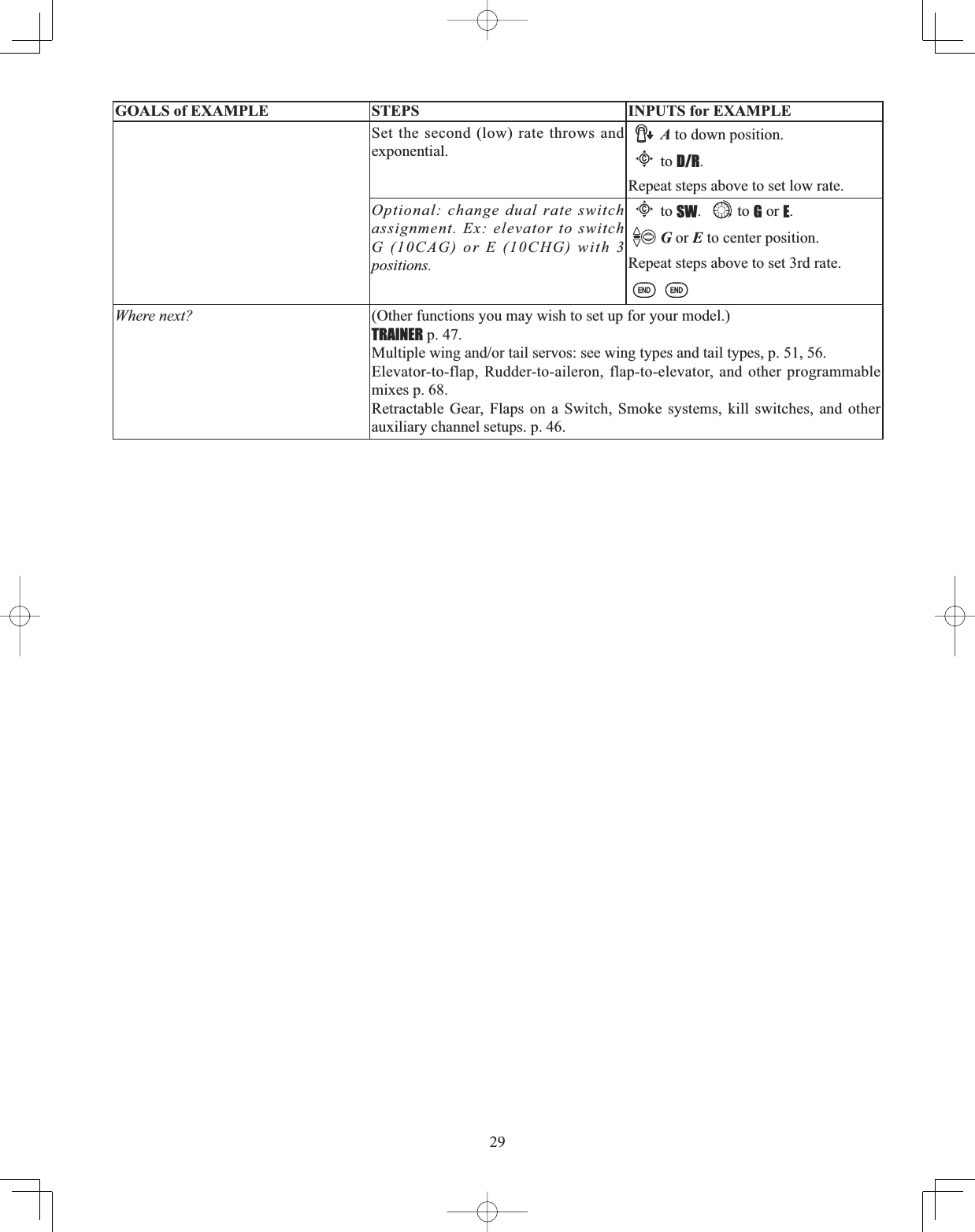
![27A QUICK GUIDE: GETTING STARTED WITH A BASIC 4-CHANNEL AIRCRAFTThis guide is intended to help you get acquainted with the radio, to give you a jump start on using your new radio, and to give you some ideas and direction in how to do even more than you may have already considered. It follows our basic format of all programming pages: a big picture overview of what we accomplish; a “by name” description of what we're doing to help acquaint you with the radio; then a step-by-step instruction to leave out the mystery when setting up your model.For additional details on each function, see that function's section in this manual. The page numbers are indicated in the goals column as a convenience to you. See p.26 for a legend of symbols used. GOALS of EXAMPLE STEPS INPUTS for EXAMPLEPrepare your aircraft. Install all servos, switches, receivers per your model's instructions. Turn on transmitter then receiver; adjust all linkages so surfaces are nearly centered. Mechanically adjust all linkages as close as possible to proper control throws. Check servo direction. Make notes now of what you will need to change during programming.Name the model. P. 32.[Note that you do not need to do anything to "save” or store this data. Only critical changes such as a MODELRESET require additional keystrokes to accept the change.]Open the BASIC menu, then open the MODEL submenu.Turn on the transmitter.for 1 second. (If ADVANCE, again.)Cas needed to highlight MODEL.to choose MODEL.Go to MODEL NAME.Cto NAME.(First character of model's name is highlighted.)Input aircraft's name. Close the MODEL submenu.WRFKDQJH¿UVWFKDUDFWHUWhen proper character is displayed,Cto move to next character.Repeat as needed.to return to BASIC menu.Reverse servos as needed for proper control operation. P. 38.In the BASIC menu, open (servo) REVERSE.Cto REVERSE.to choose REVERSE.Choose desired servo and reverse its direction of travel. (Ex: reversing rudder servo.)Cto CH4: RUDD.so REV is highlighted.Repeat as needed. Adjust Travels as needed to match model's recommended throws (usually listed as high rates). P. 39.From BASIC menu, choose END POINT.Cto END POINT.to choose END POINT.Adjust the servo's end points. (Ex: throttle servo) Close the function.Cto THROTTLE.THROTTLE STICK.until carb barrel closes as desired.THROTTLE STICK.until throttle arm just opens carb fully at full THROTTLE STICK.Repeat for each channel as needed.](https://usermanual.wiki/Futaba/T10CG-24G/User-Guide-1093539-Page-27.png)
![28With digital trims you don’t shut the engine off with THROTTLE TRIM. Let's set up IDLE-DOWN and "throttle cut" (THR-CUT)now. GOALS of EXAMPLE STEPS INPUTS for EXAMPLESet up IDLE-DOWN.P. 40. IDLE-DOWN slows the engine's idle for landings, sitting on the runway, and maneuvers such as spins. The normal (higher idle) setting (when IDLE-DOWN is off) is for engine starting, taxi, and most ÀLJKWPDQHXYHUVWRPLQLPL]HFKDQFHRIDÀDPHRXWFrom the BASIC menu, choose IDLE-DOWN.Cto IDLE-DOWN.to choose IDLE-DOWN.Activate and adjust IDLE-DOWN.Cto MIX. to OFF.C to center position. Screen now reads ON.Cto RATE.to increase rate until engine idles reliably but low enough to sit still.Optional: change switch command from C center-and-down to any other switch.(Not needed in this example.)Close the Function.THR-CUT shuts the engine off completely ZLWKWKHÀLSRIDVZLWFKP. 41. (NOTE: DO NOT assign IDLE-DOWN and THR-CUT to both positions of a 2position switch. See IDLE-DOWN for details.)From the BASIC menu, choose THR-CUT.Cto THR-CUT.to choose THR-CUT.Activate, assign SWITCH and adjust. Close the function.Cto MIX. to OFF.Cto SW. to C.Cto POSI. to DOWN.Cto RATE.C to down position.THROTTLE STICK.until throttle barrel closes completely.6HWXSGXDOWULSOHUDWHVDQGH[SRQHQWLDO(D/R,EXP).P. 42.(Note that in the middle of the left side of the screen is the name of the channel AND the switch position you are adjusting. Two or even THREE rates may be set per channel by simply choosing the desired switch and programming percentages with the switch in each of its 2 or 3 positions.)From the BASIC menu, choose D/R,EXP.Cto D/R,EXP.to choose D/R,EXP.Choose the desired control, and set the first (Ex: high) rate throws and exponential.A to up position.Cto CH:.to choose CH>2 (elevator).[note the screen reads ELEV (UP)]Cto D/R.ELEVATOR STICK.to set desired “UP” percentage.ELEVATOR STICK.as needed to adjust “DOWN” percentage (normally set the same as down.)Cto EXP.ELEVATOR STICK. to set.ELEVATOR STICK. to set.](https://usermanual.wiki/Futaba/T10CG-24G/User-Guide-1093539-Page-28.png)
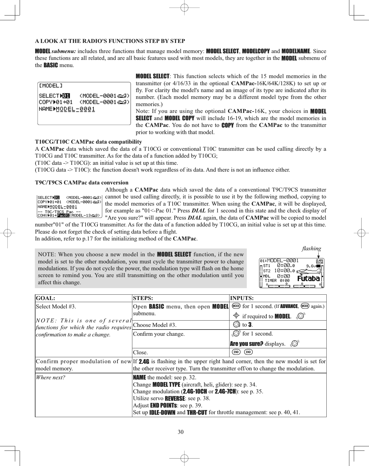
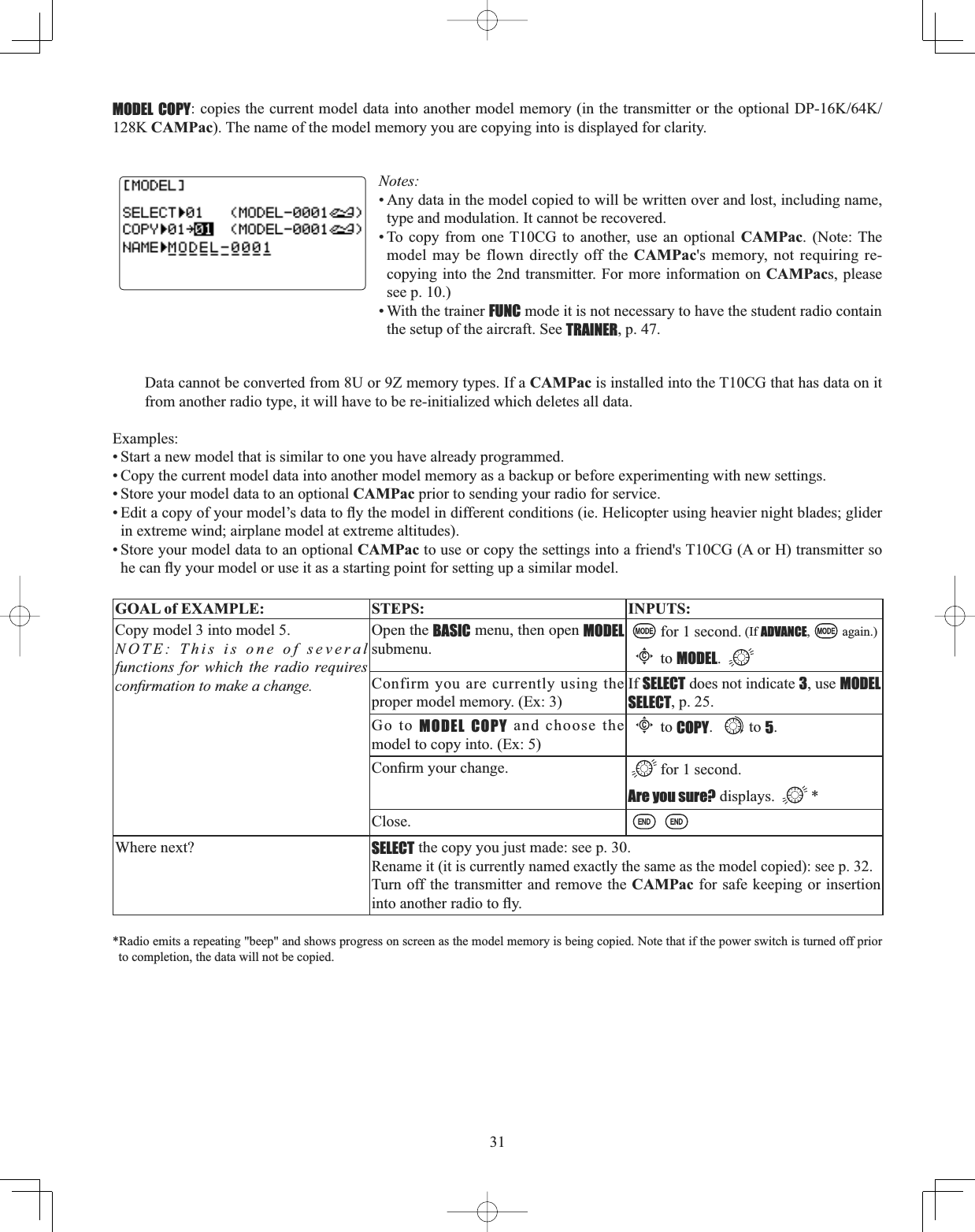
![32MODEL NAME: assigns a name to the current model memory. By giving each model a name that is immediately recognizable, \RXFDQTXLFNO\VHOHFWWKHFRUUHFWPRGHODQGPLQLPL]HWKHFKDQFHRIÀ\LQJWKHZURQJPRGHOPHPRU\ZKLFKFRXOGOHDGWRa crash. Adjustability and values: • Up to 10 characters long. • Each character may be a letter, number, blank, or a symbol. • The default names assigned by the factory are in MODEL-xxxx format (MODEL-0001 IRU¿UVWPRGHOPHPRU\HWFNOTE: When you COPY one model memory over another, everything is copied, including the model's name. Similarly, if you change MODEL TYPE or do a MODEL RESET, the entire memory is reset, including MODEL NAME6RWKH¿UVWWKLQJ\RXZLOOwant to do after you COPY a model, change its type, or start from scratch, is rename the new copy to avoid confusion. If using multiple frequency modules to be able to transmit on multiple channels, we recommend using the last 2 characters to indicate the receiver's channel for clarity. For more information on frequency transmission, see p. 8.GOAL of EXAMPLE: STEPS: INPUTS:Name model 3 “Cap-232_” (where the underline represents a blank space.)Open MODEL submenu. for 1 second. (If ADVANCE, again.)Cto MODEL.Confirm you are currently using the proper model memory. (Ex: 3)If SELECT does not indicate 3,perform MODEL SELECT, p. 25.Go to NAME and change the first character. (Ex: M to C)Cto Mto C.Choose the next character to change.CRepeat the prior steps to complete naming the model.to a(note: lower case is available)Repeat.Close.Where next? Change the MODEL TYPE to glider or helicopter: see p. 34.Change modulation [2.4G-10CH or 2.4G-7CH]: see p. 35.Utilize servo REVERSE: see p. 38.Adjust servo travel with END POINT: see p. 39.6HWXSGXDOWULSOHUDWHVDQGH[SRQHQWLDOD/R,EXP): see p. 42.](https://usermanual.wiki/Futaba/T10CG-24G/User-Guide-1093539-Page-32.png)
![33PARAMETER submenu: sets those parameters you would likely set once, and then not disturb again. Once you have selected the correct model you wish to work with, the next step is setting up the proper parameters for this VSHFL¿FPRGHO• What is the model's type? • What type is the receiver’s modulation [2.4G-10CH or 2.4G-7CH]?• Does the model have a normal throttle on channel 3 or do you need full range trim on channel 3 (ATL)?•(GLID only): The separate THR-REV settings for each model can be set.First it is important to clear out any old settings in the memory from prior use, using the MODEL RESET.MODEL RESET: completely resets all data in the individual model you have currently selected. Don't worry - there is no way you can accidentally delete all models in your radio with this function. Only a service center can completely reset your radio's entire memory at once. To delete each model in your radio's memory (for example when selling), you must SELECT each model, reset that memory, then go SELECT the next memory, etc. Note that when you COPY one model memory into another or change the model's type, you need not delete all existing data ¿UVWE\XVLQJWKLVIXQFWLRQCOPY completely overwrites anything in the existing model memory, including MODEL NAME.The MODEL TYPE function overwrites all data except name and MODUL.GOAL of EXAMPLE: STEPS: INPUTS:Reset model memory 1. NOTE: This is one of several functions for which the radio requires FRQ¿UPDWLRQWRPDNHDFKDQJHConfirm you are currently using the proper model memory. (Ex: 1)On home screen, check model name and number on top left. If it is not correct, use MODEL SELECT, p. 30.Open PARAMETER submenu. for 1 second. (If ADVANCE, again.)to 2nd page of menu. Cto PARAMETER.Reset the Memory. for one second.&RQ¿UPWKHFKDQJH Are you sure? displays. *Close.Where next? Now that the memory is reset, name has returned to the default (Ex: MODEL-0001).NAME the model: p. 32.COPY a different model into this memory: p. 31. SELECT a different model to edit or delete: p. 30. Change the MODEL TYPE to glider or helicopter: see p. 34. Change the receiver modulation [2.4G-10CH or 2.4G-7CH]: see p. 35. Utilize servo REVERSE: see p. 38. Adjust servo travel with END POINT: see p. 39. 6HWXSGXDOWULSOHUDWHVDQGH[SRQHQWLDOD/R,EXP): see p. 42.*Radio emits a repeating “beep” and shows progress on screen as the model memory is being reset. Note that if the power switch is turned off prior to completion, the data will not be reset. (ACRO)(GLID)](https://usermanual.wiki/Futaba/T10CG-24G/User-Guide-1093539-Page-33.png)
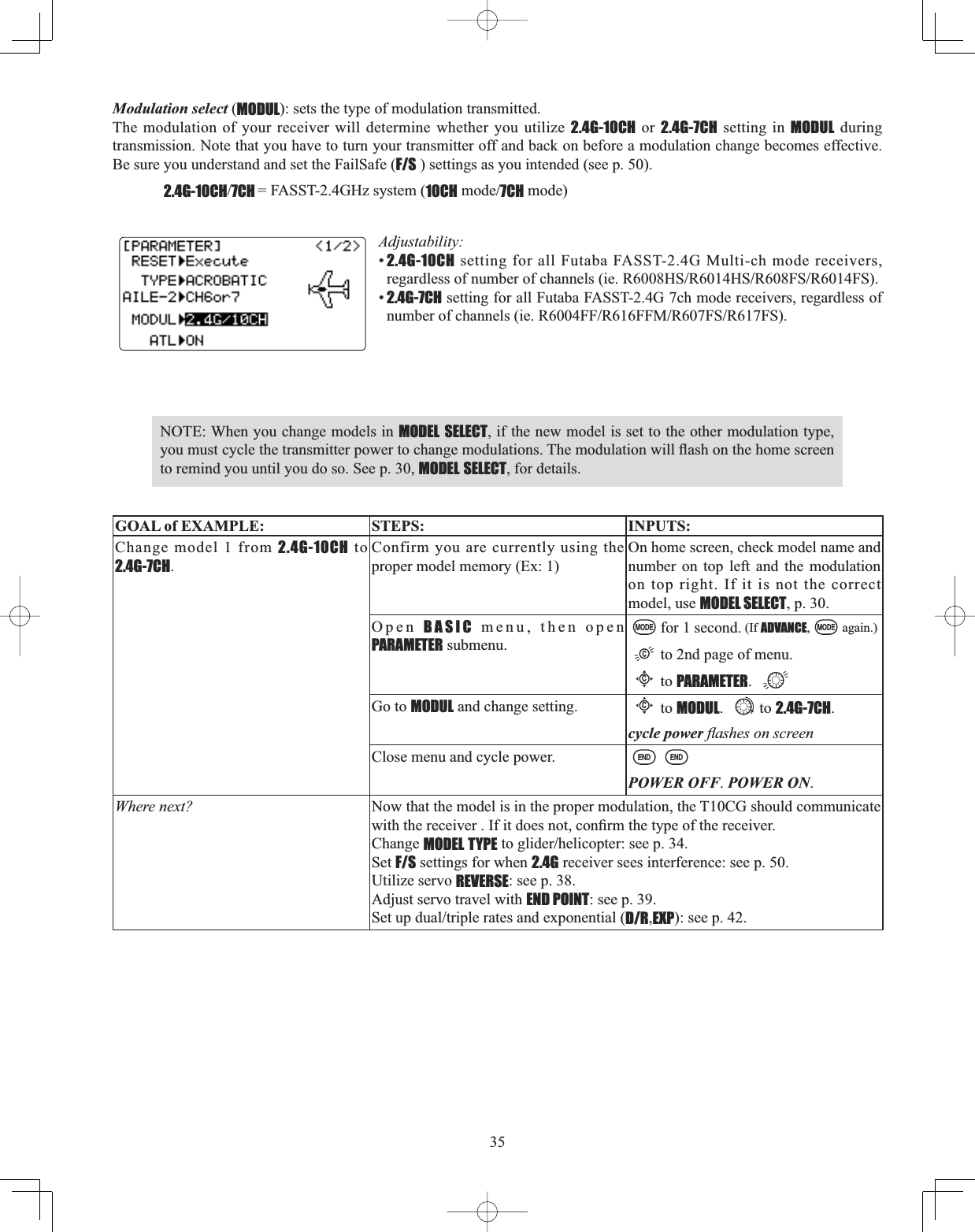
![34MODEL TYPE: sets the type of programming used for this model.The T10CG has 15 model memories, which can each support:•one powered aircraft (ACRO PHPRU\ W\SH ZLWK PXOWLSOH ZLQJ DQG WDLO FRQ¿JXUDWLRQV 6HH WZLQ DLOHURQ VHUYRV WZLQelevator servos, ELEVON, and V-TAIL for further information.); WKUHHJOLGHUZLQJW\SHVDJDLQZLWKPXOWLSOHWDLOFRQ¿JXUDWLRQV6HH*OLGHUMODEL TYPE for details, p. 78; •eight helicopter swashplate types, including CCPM. See Helicopter MODEL TYPE for details, p. 93. %HIRUHGRLQJDQ\WKLQJHOVHWRVHWXS\RXUDLUFUDIW¿UVW\RXPXVWGHFLGHZKLFKMODEL TYPEEHVW¿WVWKLVSDUWLFXODUDLUFUDIW(Each model memory may be set to a different model type.) If your transmitter is a T10CAG, the default is ACRO. If it is a T10CHG, the default is HELI(H1).ACRO is the best choice for most powered airplanes, but in some circumstances, GLID(2A+1F) may be a better choice. ACROis usually a better choice because of functions it offers that the GLID types do not: •ACRO adds: •SNAP-ROLL•AILEVATOR (twin elevator servo support) •For fuel-powered airplanes: IDLE-DOWN,THR-CUT,THROTTLE-NEEDLE mixing and THROTTLE DELAY programming. •But ACRO lacks: •5 seperate conditions for optional setups (STARTSPEEDDISTANCELANDING)If you are using a glider or heli MODEL TYPE, please go to that chapter now to select the proper model type and support your model setup. Note that changing MODEL TYPE resets all data for the model memory, including its name. GOAL of EXAMPLE: STEPS: INPUTS:Select the proper MODEL TYPE for your model. Ex: ACRO.[NOTE: This is one of several functions that requires confirmation to make a change. Only critical changes require additional keystrokes to accept the change.]Open the BASIC menu, then open the PARAMETER submenu.Turn on the transmitter.for 1 second. (If ADVANCE, again.)thenCto highlight PARAMETER.to choose PARAMETER.Go to MODEL TYPE.Cto TYPE.Select proper MODEL TYPE.Ex: ACRO.&RQ¿UPWKHFKDQJHClose PARAMETER.to ACROBATIC. for 1 second.Are you sure? displays. WRFRQ¿UPto return to BASIC menu.](https://usermanual.wiki/Futaba/T10CG-24G/User-Guide-1093539-Page-34.png)
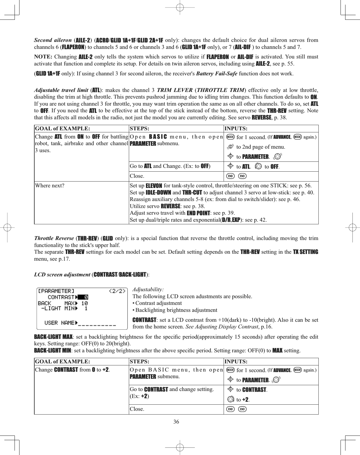
![38Servo reversing (REVERSE): changes the direction an individual servo responds to a CONTROL STICK motion. [Since channel 9 and 10 are switch only, its servo REVERSE is in the AUX-CH control screen with its switch assignment. See p. 46.] For CCPM helicopters, be sure to read the section on SWASH AFR (p. 95) before reversing any servos. Except with CCPM helicopters, always complete your servo reversing prior to any other programming. If you use pre-built ACROGLID functions that control multiple servos, such as FLAPERON or V-TAIL,it may be confusing to tell whether the servo needs to be reversed or a setting in the function needs to be reversed. See the instructions for each specialized function for further details. Always check servo direction prior to every flight as an additional SUHFDXWLRQWRFRQ¿UPSURSHUPRGHOPHPRU\KRRNXSVDQGUDGLRIXQFWLRQNOTE: THR-REV is a special function that reverses the entire throttle control, including moving the trim functionality to the Stick’s upper half. To use THR-REV, turn off the transmitter, hold down the MODE and END keys, turn on. CURSORDOWN to THR-REV and turn the DIAL to REV. Turn the transmitter off and back on. This change affects all models in the radio. (GLID only): The separate THR-REV settings for each model can be set, see p.36.GOAL of EXAMPLE: STEPS: INPUTS:Reverse the direction of the elevator servo.Open REVERSE function. for 1 second. (If ADVANCE, again.)Cto REVERSE.Choose proper channel and set direction. (Ex: ELE REV)Cto ELE.to REV. for 1 second.Close.Where next? Adjust servo travel with END POINT: see p. 39.6HWXSGXDOWULSOHUDWHVDQGH[SRQHQWLDOD/R,EXP): see p. 42.6HWXSÀLJKWWLPHUVVHHSSet up trainer functions: see p. 47.Logic switch selection (LOGIC SW): The various functions in the T10CG can be selected by switch. The Logic switch can be assigned to the following functions: THR-CUT,IDLE DOWN,AUX-CH,TIMER,PROG. MIX,AIRBRAKE,ELEV-FLAP, and AILE-FLAP functions. The logic switch can activate functions by two switches combination. The 2 types of logic, either AND or OR, can be selected.Adjustability:• Three logic switches can be used. (Lsw1,Lsw2, and Lsw3)• SW(1): Any SWICH A-H or THR-STKS, SW(2): Any SWICH A-H• Switch position (POSI)• Logic mode: AND or OR (MODE)Logic combination table:SWITCH LOGICSW(1) SW(2) AND ORoff off off offoff on off onon off off onon on on onGOAL of EXAMPLE: STEPS: INPUTS:Ex: Switch A and B are calculated by AND logic. (A = down, B = down)Open BASIC menu, then open LOGIC SW menu.for 1 second. (If ADVANCE, again.)to 2nd page of menu.Cto LOGIC SW.Go to POSI and change setting. (Ex: DOWN)Cto POSI.to DOWN.Next, SW=B,POSI=DOWN Repeat.Close.](https://usermanual.wiki/Futaba/T10CG-24G/User-Guide-1093539-Page-38.png)
![39End Point of servo travel adjustment (END POINT, also called EPA): the most flexible version of travel adjustment available. It independently adjusts each end of each individual servo’s travel, rather than one setting for the servo that affects both directions. Again, for CCPM helicopters, be sure to see SWASH AFR (see p. 95) prior to adjusting end points. Adjustability:• Can set each direction independently. • Ranges from 0% (no servo movement at all) to 140%. At a 100% setting, the throw of the servo is approximately 40° for channels 1-4 and approximately 55° for channels 5-8. • Reducing the percentage settings reduces the total servo throw in that direction. Examples:• Adjust the throttle high end to avoid binding at the carburetor, and low end to allow for proper carburetor closure. $GMXVWÀDSVRXSWUDYHOLVRQO\VXI¿FLHQWIRUVWUDLJKWDQGOHYHOÀLJKWWULPPLQJZLWKIXOOGRZQWUDYHO•END POINTPD\EHDGMXVWHGWRWRNHHSDVHUYRIURPPRYLQJRQHGLUHFWLRQVXFKDVÀDSVQRWLQWHQGHGWRDOVRRSHUDWHDVspoilers.• Retract servos are not proportional. Changing END POINT will not adjust the servo. END POINT adjusts only the individual servo. It will have no effect on any other servo that is operated in conjunction with this servo via mix or preset programming such as FLAPERON,AILEVATOR, etc. This is so that each individual servo can be FDUHIXOO\¿QHWXQHGWRDYRLGELQGLQJDQGRWKHUFRQÀLFWV7RDGMXVWWKHWRWDOWUDYHORIDIXQFWLRQVXFKDVFLAPERON, make the adjustments in that function's controls. For CCPM helicopters, adjust the total travel of the function, such as collective pitch, in SWASH AFR.Adjust the linkage or the END POINT? It is nearly always best to adjust your linkages to get as close as possible prior to utilizing END POINT. The higher the END POINT setting, the better position accuracy and the more servo power available at nearly any position (except if using digital servos). Higher END POINT values also mean longer travel time to reach the desired position, as you are utilizing more of the servo's total travel. (For example, using 50% END POINT would give you only half the steps of servo travel, meaning every click of trim has twice the effect and the servo gets there in half the time).• end point (and moving the linkage) = torque, accuracy, but transit time to get there. • end point (instead of adjusting linkages) = travel time, but torque, accuracy. GOAL of EXAMPLE: STEPS: INPUTS:Decrease the flap servo throw in the upward direction to 5% to allow WULPPLQJRI OHYHO ÀLJKW RQO\DQGGRZQtravel to 85% to prevent binding.Open END POINT function. for 1 second. (If ADVANCE, again.)Cto END POINT.Choose proper channel and move stick or knob in direction you want to adjust DQGVHWVHUYRWKURZ([ÀDSXSCto FLAP.ÀDSFRQWURO>GHIDXOWLVVR(A)].to 5%.*VR(A). to 85%.Close.Where next? Go to SERVOGLVSOD\WRFRQ¿UPGHVLUHGHQGUHVXOWVHHS0RYHDX[LOLDU\FKDQQHOVWRGLIIHUHQWGLDOVVZLWFKHVVOLGHUVVHHSSet up IDLE-DOWN and THR-CUTWRVORZFXWWKHHQJLQHVHHS6HWXSGXDOWULSOHUDWHVDQGH[SRQHQWLDOD/R,EXP): see p. 42.6HWXSÀLJKWWLPHUVVHHSSet up trainer functions: see p. 47.Set up twin aileron servos: see p. 51.Set up twin elevator servos: see p. 57.*You can reset to the initial values by pressing the DIAL for one second.](https://usermanual.wiki/Futaba/T10CG-24G/User-Guide-1093539-Page-39.png)
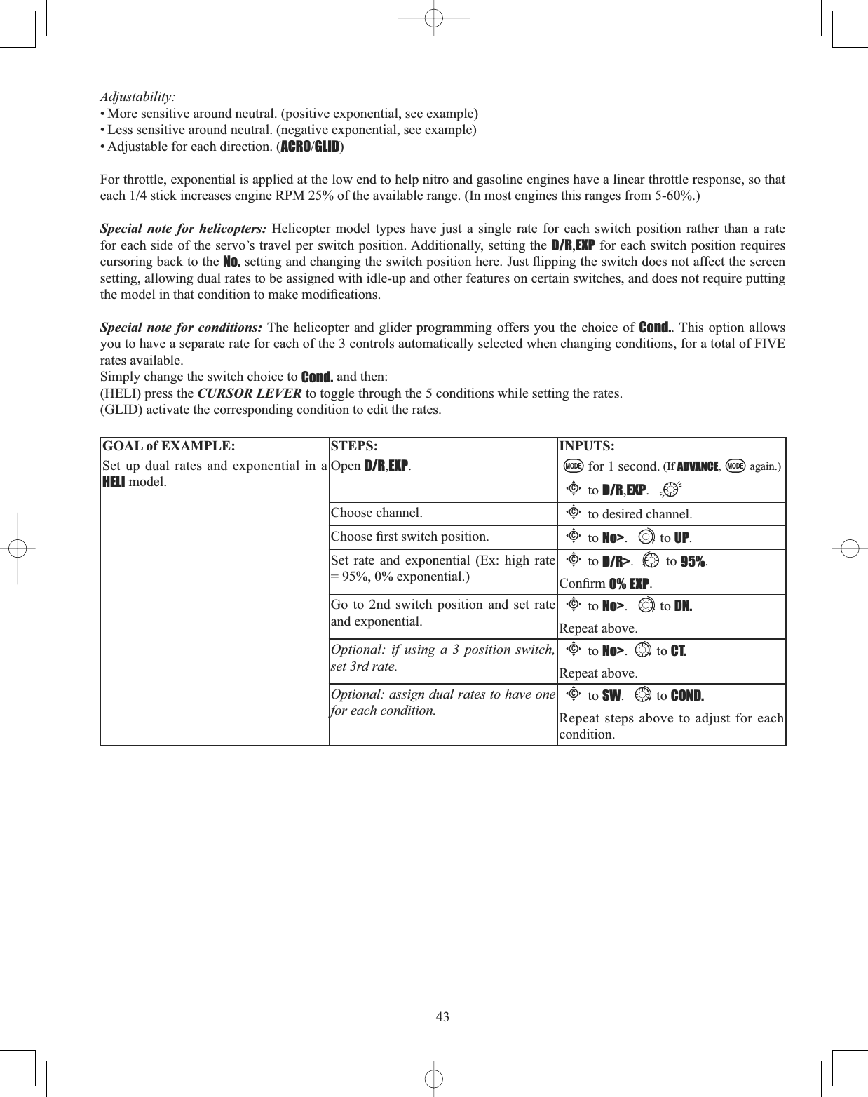
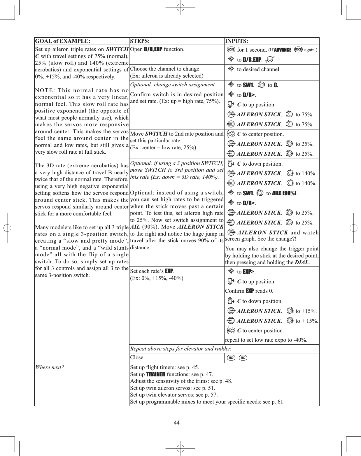
![42'XDOWULSOHUDWHVDQGH[SRQHQWLDOD/R,EXP): assigns adjusted rates and exponential. Dual/Triple Rates:UHGXFHLQFUHDVH WKHVHUYRWUDYHOE\IOLSSLQJ DVZLWFKRU(ACROGLID) they can be engaged by any stick position. Dual rates affect the control listed, such as aileron, not just a single (ex: channel 1) servo. For example, adjusting aileron dual rate will affect both aileron servos when using FLAPERON or AIL-DIF, and both aileron and elevator servos’ travel when using AILEVATOR or ELEVON or a CCPM helicopter. Activation:• Any SWITCH, A-H. If you choose a 3-position switch, then that dual rate instantly becomes a triple rate (see example). • The glider programming offers you the choice of Cond. This option allows you to have a separate rate for each of condition. (GLID)• Stick position (ACROGLID([2QUXGGHU\RXQRUPDOO\XVHRQO\WKHFHQWHURI WKH VWLFN PRYHPHQW H[FHSW IRUH[WUHPH PDQHXYHUV VXFK DV VQDSVVSLQVVWDOOV$V ORQJ DV \RXU 58''(5 67,&. GRHV QRW H[FHHG RI PD[LPXPthrow, the rudder responds at your lower rate, allowing small, gentle corrections. When the stick passes 90% (ie. stall turn), the rudder goes to high rate’s 90%, which is a MUCH higher amount of travel than your low rate at 89%.) Ex: (At 100% = 1”) Low Rate = 50% High Rate = 100%At 89% Low Rate = .45”At 90% High Rate = .9”[Note] Only if any stick is chosen by the item of "SW1", a switch can also be chosen by the item of "SW2." When operated simultaneously, the switch operation has priority over the stick operation. (ACRO)Adjustability:• Range: 0 - 140% (0 setting would deactivate the control completely.) Initial value=100%• Adjustable for each direction (ACROGLIDLH8SGRZQOHIWULJKW([0RVWPRGHOVÀ\XSULJKWZLWKRXWDQ\HOHYDWRUWULPEXWUHTXLUHVRPHGRZQHOHYDWRUZKHQLQYHUWHG MXVW WR PDLQWDLQ OHYHOÀLJKW%\LQFUHDVLQJWKHGRZQWUDYHOE\the amount required to hold the model inverted, the model now has equal travel available from level upright or level inverted.) Exponential:FKDQJHVWKHUHVSRQVHFXUYHRIWKHVHUYRVUHODWLYHWRWKHVWLFNSRVLWLRQWRPDNHÀ\LQJPRUHSOHDVDQW<RXFDQmake the servo movement less or more sensitive around neutral for rudder, aileron, elevator, and throttle (except HELI type - use THROTTLE CURVE instead). (ACRO type—throttle EXP and THROTTLE CURVE can not be activated simultaneously. Why use expo? Many models require a large amount of travel to perform their best tricks. However, without exponential, WKH\DUH³WRXFK\´DURXQGQHXWUDOPDNLQJWKHPXQSOHDVDQWWRÀ\DQGPDNLQJVPDOOFRUUHFWLRQVYHU\GLI¿FXOW$GGLWLRQDOO\by setting different exponentials for each rate, you can make the effectiveness of small corrections similar in each rate, as in our example below. The best way to understand exponential is to try it: • Having made no changes yet in the D/R,EXP screen, move SWITCH D to “down” (toward the AILERON STICK).• Cursor down to EXP and dial to +100%. • Move SWITCH D up. Hold the AILERON STICKDWVWLFNDQGPRYHSWITCH D down. • Notice how much less travel there is. *RWRVWLFNDQGUHSHDW1RWLFHKRZWKHWUDYHOLVPXFKFORVHULIQRWLGHQWLFDOHigh RateHigh RateHigh RateLow RateLow Rate100% 100%100%30%0%90% 90%0%](https://usermanual.wiki/Futaba/T10CG-24G/User-Guide-1093539-Page-42.png)
![46Auxiliary channel function (including channel 9-10 controls)(AUX-CHGH¿QHVWKHUHODWLRQVKLSEHWZHHQWKHWUDQVPLWWHUcontrols and the receiver output for channels 5-10. Also, the CH9-10 POSI are used to change the CH9-10 servo direction. Note that the CH9-10 functions are only visible in the AUX-CH screen when 2.4H-10CH modulation is selected. The 8-10th channels are not supported in 2.4G-7CH modulation.Adjustability:• Channels 5-8 may be assigned to any SWITCH (A-H),LOGIC SWITCH (Lsw1-Lsw3), slider [VR(D) and VR(E)], or knob [VR(A-C)] (for example, moving flaps to a switch or slider), but not the primary control sticks (use programmable mixes to do so, p. 68). (GLID 1A+1F only): Channel 6 may be assigned to Airbrake control stick (STK-ARBK).• Channel 9-10 may be assigned to any SWITCH (A-H),LOGIC SWITCH (Lsw1-Lsw3) and the servo direction may be changed. • Multiple channels may be assigned to the same switch, slider or knob; • Channels set to "NULL" are only controlled by mixes. (Ex: utilizing 2channels for 2 rudder servos. See mixes, p. 68.) •If GYRO SENSE,GOVERNOR, and THR-NEEDLE functions are activated, AUX-CHsettings of related channels become invalid automatically. Related channels: GYRO SENSE (ACRO): ch. 5, 7, or 8: see p. 73.GYRO SENSE (HELI): ch. 5: see p. 107.GOVERNOR (HELI): ch. 7, or ch. 7 and 8: see p. 108.THR-NEEDLE (ACROHELI): ch. 8: see p. 65.Remember that if you assign primary control of a channel to a switch which you later use for other functions (like GXDOWULSOHUDWHVRUDLUEUDNHVHYHU\WLPH\RXXVHWKDWRWKHUIXQFWLRQ\RXZLOODOVREHPRYLQJWKHDX[LOLDU\FKDQQHOGOAL of EXAMPLE: STEPS: INPUTS:$VVLJQÀDSVWRWKHULJKWVOLGHU>VR(E)]and set channel 7 to NULL in preparation to use it as a smoke system control (the smoke system being activated later by a throttle-to-ch.-7 mix).Open BASIC menu, then open AUX-CHfunction.for 1 second. (If ADVANCE, again.)to page 2.Cto AUX-CH.Choose the channel to change. (ex: ch. 6.)Cto Ch 7.Change primary control. (ex: to slider.) to Vr-E.Repeat as needed. (ex: ch. 7 to NULL.)Cto Ch 7. to NULL.Close.Where next? Programmable mixes: see p. 68.6HWXSGXDOWULSOHUDWHVDQGH[SRQHQWLDOD/R,EXP): see p. 42.Adjust SUB-TRIM of auxiliary channel to adjust center SWITCH position: see p. 49.Adjust END POINTs (sets end points of travel even when using a switch): see p. 39.](https://usermanual.wiki/Futaba/T10CG-24G/User-Guide-1093539-Page-46.png)
![47TRAINER: for training novice pilots with optional trainer cord connecting 2 transmitters. The instructor has several levels of controllability. Adjustability:•NORM: When the TRAINER SWITCH is ON, the channel set to this mode can be controlled by the student. The set channel is controlled according to any programming set at the student's transmitter. •FUNC: When the TRAINER SWITCH is ON, the channel set to this mode can be controlled by the student, controlled according to any mixing set at the instructor's transmitter. •MIX: When the TRAINER SWITCH is ON, the channel set to this mode can be controlled by both the student and the instructor, controlled according to any mixing set at the instructor's transmitter. And the student's mixing rate is adjustable. (default 30%) [Note] However, it becomes invalid even if it sets up the channel which is not in a student's transmitter. The channel serves as operation by the instructor's transmitter automatically. •OFF: The channel set to this mode cannot be controlled by the student even when the TRAINER SWITCH is ON. The set channel is controlled by the instructor only, even when the TRAINER SWITCH is ON. • SWITCH: controlled by spring-loaded SWITCH F (10CAG) or H (10CHG) only. Not assignable. • Compatibility: The 10CG may be master or student with any Futaba transmitter compatible with the cord. Simply plug the optional trainer cord (For 10CG series, sold separately) into the trainer connection on each transmitter, and follow the guidelines below.Examples::KHQWKURWWOHFROOHFWLYHDUHVHWWRFUNC,5-channel helicopter practice is possible with a 4-channel transmitter. • Set up the model in a second transmitter, use NORM mode to quickly and safely check proper operation of all functions, then allow WKHVWXGHQWUDGLRWRIXOO\À\WKHPRGHO•Using NORM mode, set lower throws, different exponentials, even different auxiliary channel settings on the student radio (if it has these features). • To ease the learning curve, elevator and aileron may be set to the NORM or FUNCmode, with the other channels set to OFF and controlled by the instructor. GOAL of EXAMPLE: STEPS: INPUTS:Turn on the TRAINER system and set up so student has: fully functional control of aileron and elevator to support FLAPERON and AILEVATOR; normal control of rudder to allow lowered travel; and no throttle channel control (with the instructor for safety).Open BASICmenu, then open TRAINERfunction.for 1 second. (If ADVANCE, again.)to page 2.Cto TRAINER.Activate TRAINER.to OFF.Choose desired channel(s) and proper training type(s).Cpast AIL and ELE (default OK).Cto THR, to OFF.Cto RUD, to NORM.Close.7(67VWXGHQWUDGLRIXQFWLRQIXOO\SULRUWRDWWHPSWLQJWRÀ\Where next? 6HWXSGXDOWULSOHUDWHVDQGH[SRQHQWLDOD/R,EXP) on student 10CG: see p.42.Reset trims on student 10CG: see p. 48.Precautions: • NEVER turn on the student transmitter power. • ALWAYS set the student transmitter modulation mode to PPM.As for a T10CG transmitter, PPM signal is always sent by the trainer jack regardless of the modulation mode.• BE SURE that the student and instructor transmitters have identical trim settings and control motions. Verify by switching back and forth while moving the control sticks. • Always remove the student transmitter's RF module (if it is a module-type transmitter). • When the TRAINER function is active, the snap roll function is deactivated. Other functions, such as IDLE-DOWN and THR-CUT, which have been assigned to the same switch, are not deactivated. Always double check your function assignments prior to utilizing the TRAINER function. • When you select a different model, the TRAINER function is deactivated in the current model for safety reasons.](https://usermanual.wiki/Futaba/T10CG-24G/User-Guide-1093539-Page-47.png)
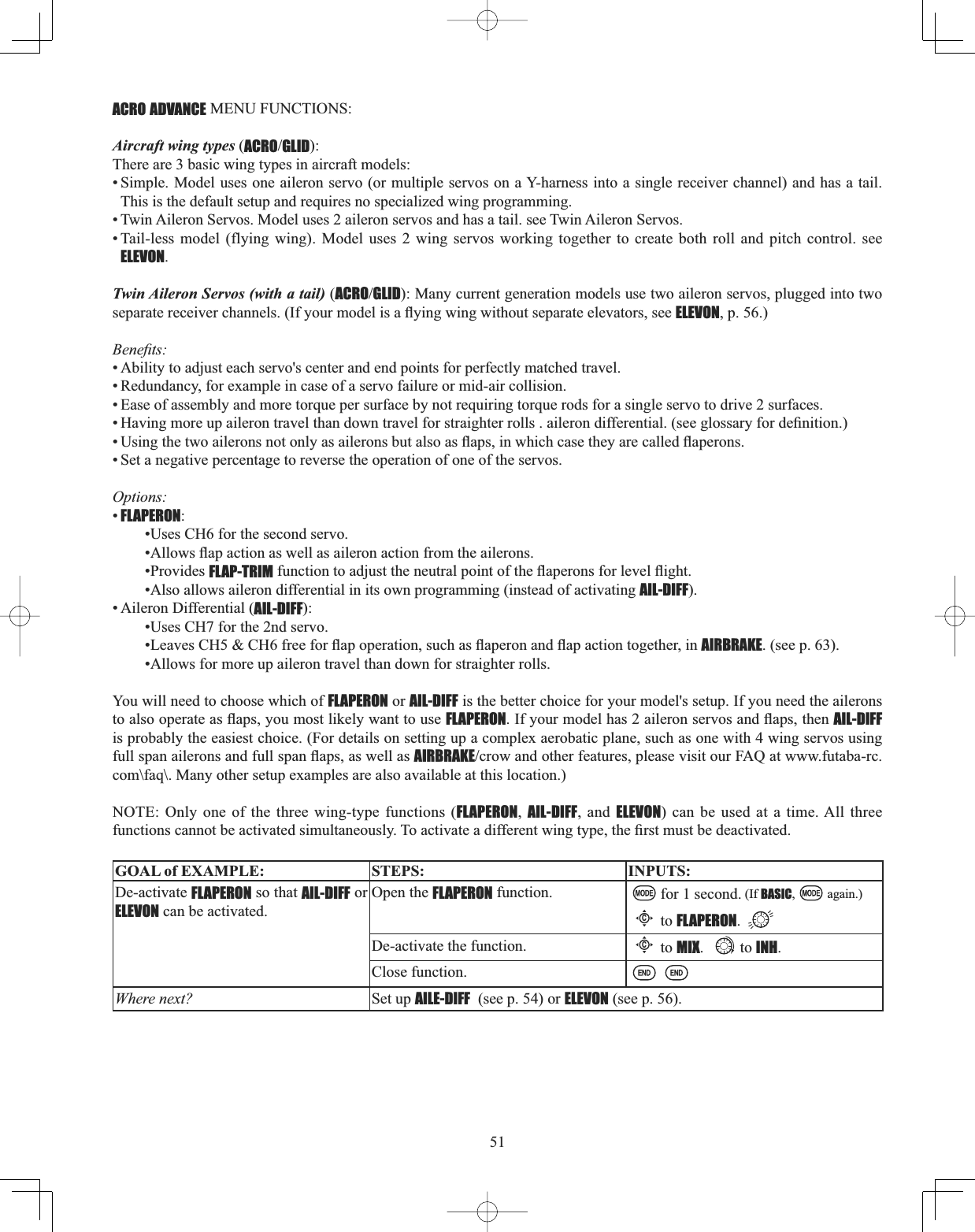
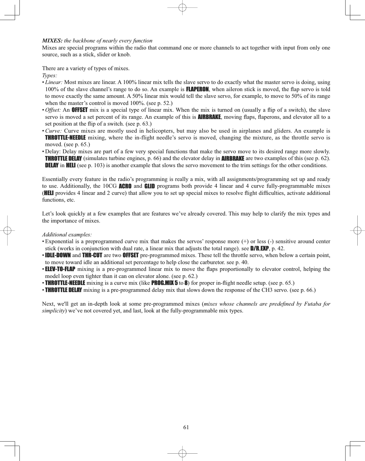
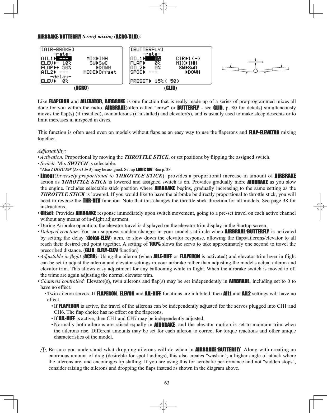
![52Using FLAPERON (ACROGLID 1A+1F ): The FLAPERONPL[LQJIXQFWLRQXVHVRQHVHUYRRQHDFKRIWKHWZRDLOHURQVDQGXVHVWKHPIRUERWKDLOHURQDQGÀDSIXQFWLRQ)RUÀDSHIIHFWWKHDLOHURQVUDLVHORZHUVLPXOWDQHRXVO\2IFRXUVHDLOHURQIXQFWLRQPRYLQJLQRSSRVLWHGLUHFWLRQVLVDOVRperformed.[Note] When changing the polarity of a rate, "change rate dir?" is displayed for a check. Please set up after pressing DIAL for 1 second and canceling an alarm display. (GLID only) Once FLAPERONLVDFWLYDWHGDQ\WLPH\RXSURJUDP&+RUÀDSLHELEVATOR-FLAP mixing), the radio commands both VHUYRVWRRSHUDWHDV ÀDSV7KHDPRXQWRIWUDYHODYDLODEOH DV ÀDSV LV LQGHSHQGHQWO\DGMXVWDEOHLQFLAPERON. A trimming feature is also available (see FLAP-TRIM WR DGMXVW ERWK QHXWUDO SRVLWLRQV WRJHWKHU IRU VWUDLJKWDQGOHYHO ÀLJKW RU VOLJKWLQFUHDVHVGHFUHDVHVRIWKHÀDSDQJOHEND POINT and SUB-TRIM both still adjust each servo individually. Adjustability:• Each aileron servo's up travel can be set separate from its down travel, creating aileron differential. (See example). (DFKDLOHURQVHUYRVWUDYHOZKHQDFWXDWHGDVDÀDSLVVHSDUDWHO\DGMXVWDEOH• The separate FLAPERON settings for each condition can be set. (GLID)127($FWLYDWLQJÀDSHURQVRQO\PDNHVWKHDLOHURQVZRUNDVDLOHURQVDQGWHOOVWKHUDGLRKRZIDU\RXZDQWWKHPWRPRYHDVÀDSV,)\RXWKHQDFWLYDWHRWKHUSURJUDPPLQJWKDWPRYHVWKHPDVÀDSVFLAP-TRIMLVWKHÀDSWULPPLQJIHDWXUHWKDWDOORZVWKHÀDSVWRPRYHLQUHDFWLRQWRWKHFKDQQHOFRQWURO,WLVPHDQWRQO\IRUWULPPLQJWKHÀDSVFHQWHUEXWFDQDOVREHXVHGDVIXOOÀDSFRQWURO6HHSAIRBRAKELVDIHDWXUHWKDWGURSVÀDSHURQVDVÀDSDQGDOVRFRPSHQVDWHVZLWKHOHYDWRULIGHVLUHG6HHSELEVATOR-FLAPZRXOGDGGHOHYDWRUPL[LQJLQWRWKHÀDSPRYHPHQWIURPWKHÀDSGLDODIWHUFLAP-TRIM is activated. GOAL of EXAMPLE: STEPS: INPUTS:Activate twin aileron servos, FLAPERON.Input 10% less down travel than up travel (aileron differential) within the FLAPERON programming. (Decrease right aileron is down travel to 90%, decrease left aileron's down travel to 90%.) $GMXVWWRWDOÀDSWUDYHODYDLODEOHWRof aileron travel available.Open the FLAPERON function. for 1 second. (If BASIC, again.)Cto FLAPERON.Activate the function.Cto MIX. to ACT.Optional: adjust the up/down travel separately for the 2 servos.(Ex: 90% down.)Cto AIL1.AILERON STICK.to 90%.Cto AIL2.AILERON STICK.to 90%.Optional: adjust the aileron's travel so WKH\PRYHDVÀDSV([HDFKVHUYR ÀDStravel to 50%.)Cto FLP2. to +50%.Cto FLP1. to -50%.Close menu.Where next? Set FLAP-TRIM: see p. 53.Set up AIRBRAKE mix: see p. 63.0L[ÀDSHURQVÀDSPRWLRQWRDQRWKHULQERDUGÀDSSOXJJHGLQWRDX[VHHS9LHZDGGLWLRQDOPRGHOVHWXSVRQWKHLQWHUQHWZZZIXWDEDUFFRPIDT* If you receive an error message that OTHER WING MIXING IS ON, you must deactivate AIL-DIFF or ELEVON. see p. 51.(GLID 1A+1F)(ACRO)](https://usermanual.wiki/Futaba/T10CG-24G/User-Guide-1093539-Page-52.png)
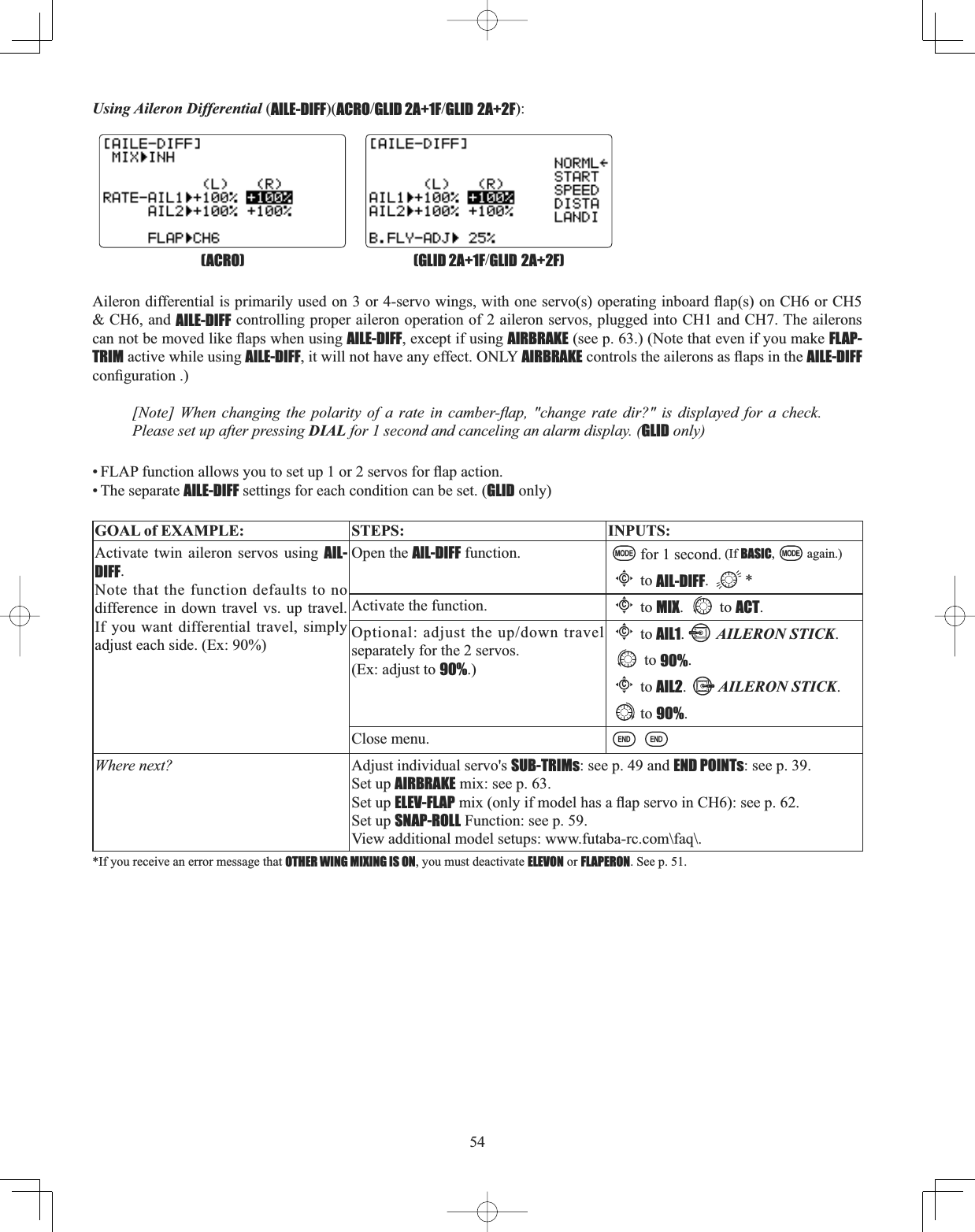
![53Using FLAP-TRIM FDPEHUWRDGMXVWÀDSHURQV (ACROGLID ) FLAP-TRIM assigns the primary flaperon control [defaults to VR(A)] to allow trimming in flight of the flap action of ÀDSHURQV1RWHHYHQLIFLAP-TRIM is made active with AIL-DIFF, it will not have any effect. The ONLY function that allows FRQWURORIWKHDLOHURQVDVÀDSVLQWKHAIL-DIFFFRQ¿JXUDWLRQLVAIRBRAKE.) Most modelers use AIRBRAKE, or programmable PL[HVWRPRYHWKHÀDSVWRDVSHFL¿HGSRVLWLRQYLDPRYHPHQWRIDVZLWFKFLAP-TRIMPD\DOVREHXVHGDVWKHSULPDU\ÀDSFRQWUROLQÀLJKW%\GRLQJVR\RXFDQDVVLJQ&+WRDSRVLWLRQVZLWFKZLWK D VSRLOHURQ QHXWUDO DQG IODSHURQ SRVLWLRQ DQG HYHQ DGMXVW WKH SHUFHQWDJH WUDYHOHG DV IODSHURQVSRLOHURQ E\changing the Flap Trim travel. (Note that there is only one setting, not independent settings for up and down travel.) GOAL of EXAMPLE: STEPS: INPUTS:Add FLAP-TRIM to allow the model's DLOHURQVWREHWULPPHGWRJHWKHUDVÀDSVat any time during the flight,with a maximum travel of 5%RI WKHWRWDOÀDStravel set in FLAPERON.Open the FLAP-TRIM function. for 1 second. (If BASIC, again.)Cto FLAP-TRIM.The function is automatically activated with FLAPERON; however, the default travel is 0.Adjust the travel available to the flaperons when turning the CH6 DIAL.(Ex: 5%).to 5%.Optional: Use as total flap control.Reassign CH6 is primary control in AUX-CHWR\RXUGHVLUHGÀDSFRQWURO(Ex: right slider)to 50%.Cto AUX-CH.Cto CH6. to Vr-E.Close menu.Where next? Adjust individual servo's SUB-TRIMs: see p. 49 and END POINTs: see p. 39. Set up AIRBRAKE mix: see p. 63 and ELEV-FLAP mix: see p. 62.0L[ÀDSHURQVÀDSPRYHPHQWWRDQDGGLWLRQDOLQERDUGÀDSSOXJJHGLQWRDX[see p. 61.View additional model setups on the internet: www.futaba-rc.com\faq\.(GLID)(ACRO)](https://usermanual.wiki/Futaba/T10CG-24G/User-Guide-1093539-Page-53.png)
![55Using Twin Aileron Servos, AILE-2 (ACROGLID ):AILE-2 only tells the radio that you are using CH5 and CH6 (FLAPERON), or CH5 and CH7 (AIL-DIFF), not CH6 or CH7, as the second servo in FLAPERON or AILE-DIFF. You still must activate and set up the FLAPERONAILE-DIFF function. Note that selecting CH6&5 or CH7&5 does NOT free up CH6 or CH7 to be used for other functions when using a receiver with more than 5 channels. Both 5 and 6 (FLAPERONAILE-DIFF) are dedicated to the FLAPERON or AILE-DIFF programming. >7KLVLVEHQH¿FLDOZLWKIRXUDLOHURQVHUYRVWKDWQHHGWRKDYHWKHLUHQGSRLQWVRUVXEWULPVVHWVHSDUDWHO\&+&+DQGCH6 are already fully set up to operate as ailerons. Mix CH7 or CH8 (the second aileron servo on the other side) into ailerons to function properly.] GOAL of EXAMPLE: STEPS: INPUTS:Adjust the second aileron servo output from CH6or7 to channels CH6&5.Allows twin aileron servo operation with a 5-channel receiver.Open the PARAMETER submenu. for 1 second. (If ADVANCE, again.)Cto PARAMETER.Select AILE-2 and change to CH6&5.Cto AILE-2. to CH6&5.Close menu.Where next? Finish setting up FLAPERON or AILE-DIFF. see Twin Aileron Servos: p. 51.View additional model setups on the internet: www.futaba-rc.com\faq\](https://usermanual.wiki/Futaba/T10CG-24G/User-Guide-1093539-Page-55.png)
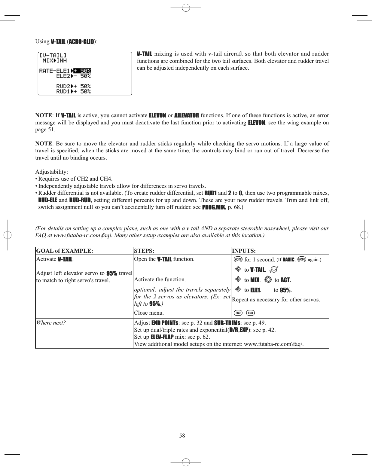
![56Aircraft tail types (ACROGLID):There are 4 basic tail types in aircraft models:• Simple. Model uses one elevator servo and one rudder servo (or multiple servos on a Y-harness). This is the default. • Dual Elevator servos. Model uses 2 elevator servos. see AILEVATOR (ACRO) see p. 57. •Tail-less model. Model uses 2 wing servos together to create roll and pitch control. see ELEVON(ACROGLID 1A+1F). see p. 56. •V-TAIL. Model uses 2 surfaces, at an angle, together to create yaw and pitch control. see V-TAIL (ACROGLID). see p. 58. Note: Only one of the three tail-type functions (AILEVATOR,V-TAIL, and ELEVON) can be used at a time. The radio provides a ZDUQLQJDQGZLOOQRWDOORZWKHDFWLYDWLRQRIDQRWKHUWDLOW\SHXQWLOWKH¿UVWLVGHDFWLYDWHG$QHUURUPHVVDJHRIOTHER WING MIXING IS ON will display. (See the wing type example on page 51.) Using ELEVON(ACROGLID 1A+1FXVHGZLWKGHOWDZLQJVÀ\LQJZLQJVDQGRWKHUWDLOOHVVDLUFUDIWWKDWFRPELQHDLOHURQDQGHOHYDWRUIXQFWLRQV XVLQJ WZR VHUYRV RQHRQ HDFK HOHYRQ7KH DLOHURQHOHYDWRU UHVSRQVHV RIHDFK VHUYR FDQ EH DGMXVWHGindependently. This is also popular for ground model use, such as tanks, which drive two motors together for forward, and RQHPRWRUIRUZDUGRQHEDFNZDUGIRUWXUQLQJAdjustability:• Requires use of CH1 and CH2.• Independently adjustable aileron travel allows aileron differential. • Independently adjustable elevator travel allows for differences in up vs. down travel.• The separate ELEVON settings for each condition can be set. (GLID only)[Note] When changing the polarity of a rate, "change rate dir?" is displayed for a check. Please set up after pressing DIAL for 1 second and canceling an alarm display. (GLID only) NOTE: If ELEVON is active, you cannot activate FLAPERON, AILE-DIFF, or AILEVATOR. An error message OTHER WING MIXING IS ON displays and you must deactivate the last function to activate ELEVON.127(%HVXUHWRPRYHWKHHOHYDWRUDQGDLOHURQVWLFNVWRIXOOGHÀHFWLRQGXULQJsetup. If large travels are specified, when the AILERON and ELEVATOR STICKS are moved at the same time the controls may bind or run out of travel. (For details on setting up a complex aerobatic plane, please visit www.futaba-rc.com\faq\. Many other setup examples are also available at this location. )GOAL of EXAMPLE: STEPS: INPUTS:Activate ELEVON.Adjust aileron down travel to 90% of up travel, creating aileron differential.Open the ELEVON function. for 1 second. (If BASIC, again.)Cto ELEVON.Activate the function.Cto MIX. to ACT.Optional: adjust the up/down travel separately for the servos as ailerons. (Ex: down to 90%.)Cto AIL1.AILERON STICK.to 90%.Cto AIL2.AILERON STICK.to 90%.Optional: adjust the elevator travel of each servo. (Ex: right servo elev. travel to 98%, left to 105%.)Cto ELE2. to 98%.Cto ELE1. to 105%.Close menu.Where next? Adjust individual servo's SUB-TRIMs: see p. 49 and END POINTs: see p. 39. 6HWXSGXDOWULSOHUDWHVDQGH[SRQHQWLDOD/R,EXP): see p. 42.View additional model setups on the internet: www.futaba-rc.com\faq.html(GLID 1A+1F)(ACRO)](https://usermanual.wiki/Futaba/T10CG-24G/User-Guide-1093539-Page-56.png)
![57Dual Elevator Servos (with a rudder) (AILEVATOR) (ACRO): Many models use two elevator servos, plugged in separate receiver channels. (Flying wings without a separate aileron control use ELEVON. V-shaped tail models use V-TAIL, p. 58. %HQH¿WV• Ability to adjust each servo's center and end points for perfectly matched travel.• Ease of assembly, not requiring torque rods for a single servo to drive 2surfaces.(OHYDWRUVDFWLQJ DOVRDVDLOHURQVIRU H[WUHPHVWXQWÀ\LQJRU PRUHUHDOLVWLFMHWÀ\LQJRSWLRQDO• Redundancy, for example in case of a servo failure or mid-air collision. Adjustability:• CH2 and CH8 only. (With programmable mixing, could utilize CH5 as the 2nd elevator servo. See www.futaba-rc.com\faq\ for examples.) THROTTLE-NEEDLE uses CH8 and cannot be active simultaneously. • Direction of each servo's travel may be reversed in REVERSE or the set percentages may be reversed here. • Elevator travels independently adjustable (both directions and percent). • Optional action as ailerons (defaults to 50%UHVSRQVH7KLV UHVSRQVHFDQQRWEH DFWLYDWHGGHDFWLYDWHG LQ ÀLJKW 6HWWLQJAIL1 and 2 to 0GLVDEOHVWKLVIHDWXUH1RWHLI\RXZDQWWKLVEXWRQRIIZLWKDVZLWFKVHW AIL1 and 2 to 0 here, and use 2mixes . AIL-to-ELEV and AIL-to-AUX2OLQNWULPRIIDVVLJQDVZLWFKWRJHWDLOHURQDFWLRQIURPWKHHOHYDWRUVHUYRVZKHQWKHassigned switch is on. See p. 68. )RUGHWDLOVRQVHWWLQJXSDFRPSOH[DHUREDWLFSODQHVXFKDVRQHZLWKZLQJVHUYRVIXOOVSDQDLOHURQVÀDSVAIRBRAKE/crow etc, please visit www.futaba-rc.com\faq\. Many other setups are also available.) The AILEVATOR mixing function uses one servo on each of the two elevators, and combines the elevator function with the aileron function (unless aileron travel is set to 0). For aileron effect, the elevators are raised and lowered opposite of one another in conjunction with the ailerons. Once AILEVATORLVDFWLYDWHGXQOHVV\RX]HURRXWWKHDLOHURQ¿JXUHVVHHEHORZDQ\WLPH\RXPRYH\RXUDLOHURQVRUDQ\programming moves your ailerons (ie. RUDDER-AILERON mixing), the radio automatically commands both elevator servos to also operate as ailerons. To deactivate this action, simply set the 2 aileron travel settings to 0 in the AILEVATOR function. This way the elevators will work only as elevators. ,IXVLQJWKHHOHYDWRUVDVDLOHURQVDVZHOOEHVXUHWRPRYHWKHHOHYDWRUDLOHURQVWLFNZKLOHFKHFNLQJWKHVHUYRPRWLRQV,IDODUJHWUDYHOLVVSHFL¿HGZKHQWKHVWLFNVDUHPRYHGDWWKHVDPHWLPHFRQWUROVPD\ELQGRUUXQRXWRIWUDYHOGOAL of EXAMPLE: STEPS: INPUTS:Activate twin elevator servos.Deactivate the elevator-acting-as-ailerons portion of this function.Note: Depending upon your model's geometry, you may need to reverse oneservo or set a negative percentage here.Open the AILEVATOR function. for 1 second. (If BASIC, again.)Cto AILEVATOR.Activate the function.Cto MIX. to ACT.Optional: adjust up/down travel when operating as ailerons. (Ex: 0.)Cto AIL3. to 0%.Cto AIL4. to 0%.Optional: adjust total elevator travel of each servo. (Ex: right servo elevator travel to 98%, left to 96%.)Cto ELE2. to 98%.Cto ELE1. to 96%.Close menu.Where next? Adjust individual servo's SUB-TRIMs: see p. 49 and END POINTs: see p. 39.Set up Twin Aileron Servos: see p. 51.Set up AIRBRAKE mix: see p. 63.](https://usermanual.wiki/Futaba/T10CG-24G/User-Guide-1093539-Page-57.png)
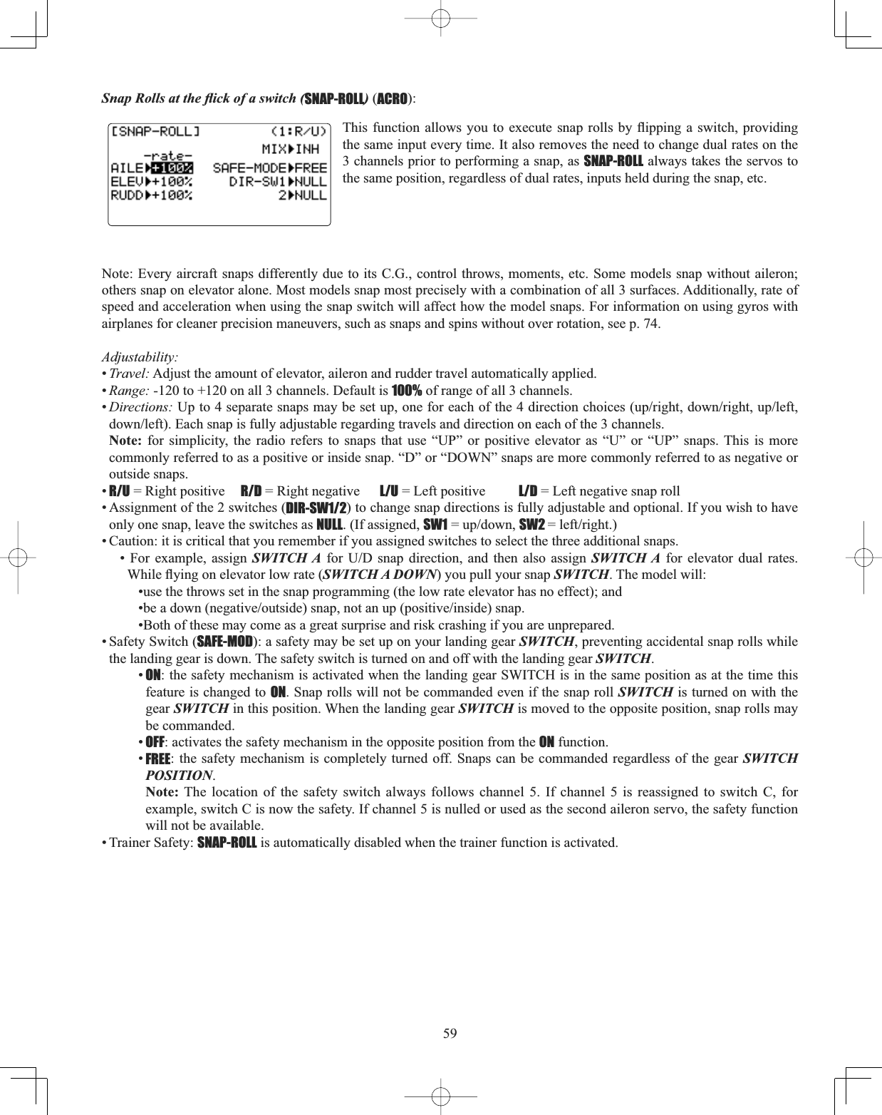
![60GOAL of EXAMPLE: STEPS: INPUTS:Activate SNAP-ROLL. Adjust elevatortravel to 55%, rudder travel to 120%LQWKHULJKWXSVQDS$FWLYDWHSAFE-MOD so snaps can not be performed when gear is down. $GMXVWUXGGHUWUDYHOLQWKHOHIWGRZQsnap to 105%.(Note: using negative percents can change any of the 4 snap directions. For example, change snap 1 to "down" by changing the elevator percent to -100%.)Open the SNAP-ROLL function. for 1 second. (If BASIC, again.)Cto SNAP-ROLL.Activate the function.Cto MIX. to OFF or ON.Adjust the travels as needed. (Ex: elevator to 55%, rudder to 120%.)Cto ELEV. to 55%.Cto RUDD. to 120%.Optional: Activate SAFE-MOD. [Ex: ON when SWITCH E (10CAG) or G (10CHG) is down, meaning snap function is deactivated when that switch is in the down position.]E or G up. Cto SAFE-MODEto ON.snap switch. Notice MIX reading is still OFF.E or G down. Notice MIX reading changes to ON.Optional: Assign switches to up/down and left/right. (Ex: Change to the left/down snap and adjust rudder to 105%.)Cto SW1. to A.Cto SW2. to B.A down B down. Repeat steps above to set percentages.Close menu.Where next? Set up programmable mixes: see p. 61. View additional setups on the internet:www.futaba-rc.com\faq\.](https://usermanual.wiki/Futaba/T10CG-24G/User-Guide-1093539-Page-60.png)
![65THROTTLE-NEEDLE mixing (ACROHELI):THROTTLE-NEEDLELVDSUHSURJUDPPHGPL[WKDWDXWRPDWLFDOO\PRYHVDQLQÀLJKWPL[WXUHVHUYR&+LQUHVSRQVHWRWKHTHROTTLE STICK inputs for perfect engine tuning at all throttle settings. This function is particularly popular with FRQWHVW SLORWV ZKR À\ LQ D ODUJH YDULHW\ RI ORFDWLRQV QHHGLQJ UHJXODU HQJLQH WXQLQJ DGMXVWPHQWV DQG UHTXLULQJ SHUIHFWHQJLQHUHVSRQVHDWDOOWLPHVDQGLQDOOPDQHXYHUV$OVRSRSXODUWRPLQLPL]HÀRRGLQJDWLGOHRILQYHUWHGHQJLQHLQVWDOODWLRQVor installations with a high tank position. Not needed for fuel injection engines, which do this automatically. Adjustability:• Five-point curve allows adjustment of engine mixture at varied throttle settings. 7KHLQÀLJKWPL[WXUHVHUYRPXVWFRQQHFWWRUHFHLYHU&+,QÀLJKWPL[WXUHVHUYRPD\DOVREHXVHGDVDVHFRQGVHUYRIRUWXQLQJDWZLQ7KURWWOHFXWIHDWXUHDOVRPRYHVWKHLQÀLJKWQHHGOHVHUYR• The CH8 knob adjusts the high throttle mixture (may be deactivated. see AUX-CH).• Because both use CH8, this function cannot be used simultaneously with AILEVATOR.• An acceleration (ACCE) function (ACRO only) helps the engine compensate for sudden, large amounts of throttle input by making the mixture suddenly richer, then easing it back to the proper adjustment for that throttle setting. This function UHTXLUHVVRPHDGMXVWPHQWWREHVW¿W\RXUHQJLQHDQG\RXUÀ\LQJVW\OH$GMXVWHQJLQH¶VUHVSRQVHXQWLOQRKHVLWDWLRQRFFXUVon rapid throttle input. • Separate curves are available (HELI only) for normal, idle-ups 1 and 2 combined, and idle-up 3. Immediately below MIXthe radio displays the curve you are editing; ex: >NORML; and then which condition is currently active by your switches ex: (ID1/2). Note that you can edit the mix for a different condition without being in that condition, to allow editing without having to shut off the helicopter’s engine every time. Be sure you are editing the proper curve by checking the name after the > and not the one in parentheses. GOAL of EXAMPLE: STEPS: INPUTS:Activate THROTTLE-NEEDLE mixing.Adjust the points as follows to resolve a slight lean midrange problem:1: 40%2: 45%3: 65%4: 55%5: 40%Open the THROTTLE-NEEDLE function. for 1 second. (If BASIC, again.)to page 2.Cto THROTTLE-NEEDLE.Activate the function.Cto MIX. to ACT.HELI only. Select the condition to edit.Cto MIX. to ACT. as needed. Adjust the travels as needed to match your engine by slowly moving the stick to each of the 5 points, then adjusting the percentage at that point until the engine is properly tuned.Cto POINT-.THROTTLE STICK to POINT1.to 40%.until POINT 2 is highlighted. to 45%.to POINT 3. to 65%.to POINT 4. to 55%.to POINT 5. to 40%(HELI)(ACRO)](https://usermanual.wiki/Futaba/T10CG-24G/User-Guide-1093539-Page-65.png)
![74Special Additions, Functions, And Added Equipment Commonly Used On Powered Aircraft Gyros: -XVWDVWRUTXHURWDWHVDQDLUFUDIWRQWKHUXQZD\GXULQJWDNHRIIKHOLFRSWHUV VWUXJJOH ZLWK WRUTXH WZLVWLQJ WKHmodel every time throttle is applied. For many years gyroscopes have been used on model helicopters to control this. In competition aerobatics and scale aircraft competition alike, the usefulness of gyros has recently come to light. For in-depth information on gyro types, please see p. 106. )RUDHUREDWLFVJ\URVRQUXGGHUDQGHOHYDWRU¿[RYHUURWDWLRQRIVQDSVDQGVSLQVDVZHOODVWDLOZDJJLQJLQVWDOOWXUQV)XWDEDoffers a twin-axis gyro, GYA-352, that controls two axes with a single gyro.) For 3D aerobatics (below stall speed, such as WRUTXHUROOVKHDGLQJKROG$9&6J\URVRQUXGGHUDQGHOHYDWRUGUDPDWLFDOO\VLPSOLI\WKHVHPDQHXYHUV)RUVFDOHPRGHOVgyros are frequently used to simplify take-offs and landings by keeping the model straight during throttle application. $OZD\V EH FDUHIXO LI XVLQJ D KHDGLQJKROG$9&6 J\UR DV LW ZLOO FRUUHFW DQ\ FKDQJH LQ \DZ WKDW LV QRW FDXVHG E\PRYHPHQWRIWKHUXGGHUOLNHPDNLQJDWXUQ ZLWK MXVW DLOHURQ DQG HOHYDWRU7\SLFDOO\ PRGHOHUV XVH KHDGLQJKROG$9&6VHWWLQJVRQO\IRUVSHFL¿FPDQHXYHUVVXFKDVWDNHRIIVDQGWRUTXHUROOVWKHQVZLWFKWRQRUPDOPRGHRU2))IRUWKHUHPDLQGHURIWKHÀLJKWWRDYRLGWKLVULVNRetracts: Retractable landing gear is often used on scale models for increased realism and on high performance models to decrease drag. The gear servo is typically plugged into CH5, which defaults to a 2-position switch for simplicity. Mechanical retracts require the use of a specialized non-proportional retract servo. Retract servos go from full travel one direction to full travel the other direction, then mechanically hold the gear into the locked position. A regular servo used for mechanical retracts will continue to draw full power the entire time, prematurely draining the battery and risking crash of your model. End point will not adjust a retract servo. Pneumatic (air driven) retracts use a standard servo to control an air valve which directs air into or out of the retract units, moving the gear up or down. Pneumatics are easier to install but require added maintenance of the air system. Gear Doors: Some scale models with retracts also have separate gear doors to cover the scale gear. For one example of how to operate the gear doors separately from the retracts, please visit our website: www.futaba-rc.com\faq\. Smoke Systems: Many scale and aerobatic models use smoke systems to provide increased realism or a more impressive GHPRQVWUDWLRQ 7KHUH DUH PDQ\ VPRNH V\VWHPV DYDLODEOH ZLWK YDU\LQJ W\SHV RI FRQWURO 0RVW XVH D VHUYR WR LQFUHDVHGHFUHDVHWKHÀRZRIVPRNHÀXLGLQWRWKHVSHFLDOL]HGVPRNHPXIÀHU7KHRLOLVKHDWHGLQWKHPXIÀHUFUHDWLQJVPRNHIt is a good practice to set up a "safety" that shuts off the smoke oil if the throttle is lowered below half-stick. For a detailed example of a smoke system setup, please visit our website: www.futaba-rc.com\faq\. Kill Switches: For safety reasons, it is strongly recommended that an electronic kill switch be installed in all gasoline-SRZHUHGDLUFUDIW,QFDVHRIDQ\W\SHRILQÀLJKWSUREOHPVXFKDVSURSIDLOXUHH[KDXVWYLEUDWLQJRIIWKURWWOHVHUYRIDLOXUHUDGLRLQWHUIHUHQFHWKHPRGHOHUFDQVKXWWKHHQJLQHRIITXLFNO\DQGVDIHO\LQÀLJKW$GGLWLRQDOO\)DLO6DIH)6VHWWLQJVDUHUHFRPPHQGHGWRVKXWWKHHQJLQHRIILQFDVHRIVXI¿FLHQWLQWHUIHUHQFHWRWULJJHUWKH)DLO6DIHVHWWLQJVLastly, an electronic kill switch set to "off" prior to the aircraft's power being shut off adds an additional safety should someone accidentally turn on the mechanical kill switch on the exterior of the model. Bomb Drops, Paratroopers, and other Released Items: Many sport and scale models include one or more of these fun add-ons. Typically, all are controlled by a simple micro-switch plugged into CH9 or CH10. The switch is assigned in AUX-CH.](https://usermanual.wiki/Futaba/T10CG-24G/User-Guide-1093539-Page-74.png)
![76GETTING STARTED WITH A BASIC 4-CHANNEL (Aileron/Flap/Rudder/Elevator) GLIDER This guideline is intended to help you get acquainted with the radio, to give you a jump start on using your new radio, and to give you some ideas and direction in how to do even more with this powerful system than you may have already considered. It follows our basic format of all programming pages: a big picture overview of what we’re trying to accomplish; a “by name” description of the steps to help acquaint you with the radio; and a step-by-step instruction to leave out the mystery and challenge of setting up your model. For additional details on utilizing each function, see that function’s section in this manual—the page numbers are indicated LQWKH¿UVWFROXPQDVDFRQYHQLHQFHWR\RXGOAL of EXAMPLE: STEPS: INPUTS:Prepare your aircraft. Install all servos, switches, receiver per your model’s instructions. Turn on transmitter then receiver; adjust all linkages so surfaces are nearly centered.Mechanically adjust all linkages to get as close as possible to proper control throws and minimize binding prior to radio set up.Check servo direction and throws.Make notes now of what you will need to change during programming.Select the proper MODEL TYPE for your model. (Ex: GLID 1A+1F.) See p. 78.[NOTE: This is one of several functions that requires confirmation to make a change. Only critical changes such as aMODEL RESET require additional key strokes to accept the change.]In the BASIC menu, open the PARAMETER submenu.Turn on the transmitter.for 1 second. (If ADVANCE, again.)thenCto highlight PARAMETER.to choose PARAMETER.Go to MODEL TYPE.Cto MODEL TYPE.Select proper MODEL TYPE.Ex:GLID(1A+1F).&RQ¿UPWKHFKDQJHClose the PARAMETER submenu.to GLID(1A+1F).for 1 second.Are you sure? Displays. WRFRQ¿UPto return to BASIC menu.NAME the model.P. 32.(Note that you do not need to do anything to "save" or store this data.)In the BASIC menu, open the MODEL submenu.Cas needed to highlight MODEL.to choose MODEL.Go to MODEL NAME.Cto NAME.(1st character of model’s name is highlighted.)Input aircraft’s name.Close the MODEL submenu when done.WRFKDQJH¿UVWFKDUDFWHUWhen proper character is displayed, Cto move to next character and repeat.to return to BASIC menu.REVERSE servos as needed for proper control operation.P. 38.In the BASIC menu, open (servo) REVERSE.Cto REVERSE.to choose REVERSE.Choose desired servo and reverse its direction of travel. (Ex: reverserudder servo.)Cto CH4:RUDD.so REV is highlighted.Are you sure? Displays. for 1 second.Repeat as needed.to return to BASIC menu.](https://usermanual.wiki/Futaba/T10CG-24G/User-Guide-1093539-Page-76.png)
![77GOAL of EXAMPLE: STEPS: INPUTS:Adjust travels as needed to match model’s recommended throws (usually listed as high rates).P. 39.In the BASIC menu, choose END POINT.Cto END POINT.to choose END POINT.Adjust the servos’ end points.([ÀDSVHUYRClose the function.Cto FLAP.VR(A) until travel as desired.VR(A). Repeat as needed. 6HWXSGXDOWULSOHUDWHVDQGH[SRQHQWLDO(D/R,EXP)P. 42.(Note that in the middle of the left sideof the screen is the name of the channel and the SWITCH position you are adjusting. Two or even three rates maybe set per channel by simply choosing the desired SWITCH and programming percentages with the SWITCHLQHDFKRILWVSRVLWLRQVChoose D/R,EXP.Cto D/R,EXP.to choose D/R,EXP.Choose the desired control, and set the first (Ex: high) rate throws and exponential.Cto CH>.to choose CH>2 (elevator).A to up position. [Note screen reads ELEV(UP)]Cto D/R.ELEVATOR STICK. to set.ELEVATOR STICK. to set.(Normally the same for both directions.)Cto EXP.ELEVATOR STICK. to set.ELEVATOR STICK. to set.Set the second (low) rate throws and exponential.Cto D/R.A to down position.Repeat above to set low rate.Optional: change dual rate SWITCHassignment. Ex: elevator to SWITCH Gwith 3 positions.Cto SW. to G.G to center position.Repeat steps above to set 3rd rate.0RYHÀDSFRQWUROIURPWKH95$GLDOto the left slider [VR(D)]. (AUX-CH)p. 46.In the BASICmenu, open AUX-CH.Cto AUX-CH. to choose AUX-CH.Choose CH6ÀDSChange primary control to VR(D).Change other channels as needed.Cto CH6.to VR(D).Repeat as required.Return to the home screen.Where next? (Other functions you may wish to set up for your model.)TRAINER p. 47.Multiple wing or tail servos. See wing types and tail types: p. 51, 56.OFFSETS,BUTTERFLY(AIRBRAKEFURZDQGRWKHUSURJUDPPDEOHPL[HVSRetractable Gear, Smoke systems, kill switches, and other auxiliary channel setups: p. 46.Adjusting SUB-TRIMs to match servo centers: p. 49.](https://usermanual.wiki/Futaba/T10CG-24G/User-Guide-1093539-Page-77.png)
![86Flap Setting (CAMBER FLAP)(GLID):CAMBER FLAP assigns the primary flap control [defaults to VR(A)] to allow WULPPLQJLQÀLJKWRIWKHÀDSDFWLRQ7KHXSGRZQWUDYHORIHDFKIODSFDPEHUIODSVFLP12) can be adjusted LQGHSHQGHQWO\$OVRWKHFHQWHUSRVLWLRQRIÀDSVHUYRFDQEHRIIVHWNOTE: If FLAP-TRIM is activated, you can not use CAMBER FLAP function simultaneously.[Note] When changing the polarity of a rate, "change rate dir?" is displayed for a check. Please set up after pressing DIAL for 1 second and canceling an alarm display. GOAL of EXAMPLE: STEPS: INPUTS:Ex: Set the maximum travel of 35% of WKHWRWDOÀDSWUDYHOOpen the CAMBER FLAP function. for 1 second. (If BASIC, again.)Cto CAMBER FLAP.$GMXVWWKHXSGRZQWULPDPRXQWseparately. (Ex: adjust to 35%.)Cto FLP1.VR(A). to 35%. VR(A). to 35%. Repeat.Option: Adjust the center position of ÀDSVHUYRCto CENTER. to desired point.Close menu.Adjustability:•Rate: -100% to +100%, with a default of +30%•Center position (CENTER7KHRSHUDWLRQUHIHUHQFHSRLQWRIÀDSFDQEHRIIVHWWRZLWKDGHIDXOWRI](https://usermanual.wiki/Futaba/T10CG-24G/User-Guide-1093539-Page-86.png)
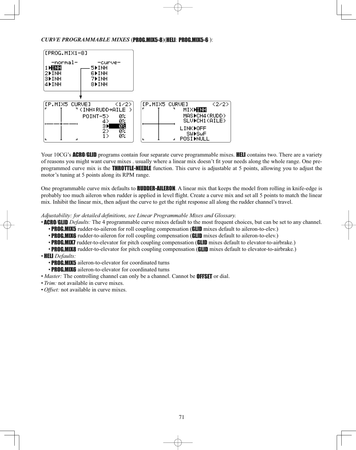
![89HELICOPTER MODEL FUNCTIONS Please note that nearly all of the BASIC menu functions are the same for airplane (ACRO setup), sailplane (GLID setups), and helicopter (HELI) setups. The features that are identical refer back to the ACRO chapter. The Helicopter BASIC menu includes the normal condition's throttle and collective pitch curves and revo. mixing. (idle-ups and throttle hold are advanced features and are in the ADVANCE menu). HELICOPTER FUNCTIONS.......................................... 89Table of contents and reference info for helicopters . 89Getting Started with a Basic Helicopter ................... 90HELI BASIC MENU FUNCTIONS .................................. 93MODEL Submenu: MODEL SELECT,COPY,NAME .......... 30 PARAMETER Submenu: RESET, MODUL, ATL, AILE-2,CONTRAST,BACK-LIGHT,HOME-DISP,USER NAME,LOGIC SW ............................................................................. 33MODEL TYPE (PARAMETERS submenu) ........................ 93Servo REVERSE ........................................................... 38SWASH AFR (swashplate surface direction and travelcorrection) (not in H-1) .............................................. 95END POINT .................................................................. 39Setting up the Normal Flight Condition ................... 97THR-CUTVSHFLDOL]HGVHWWLQJVIRUKHOLFRSWHUVSHFL¿Fmodels) ..................................................................... 98'XDO7ULSOH5DWHVDQG([SRQHQWLDOD/R,EXP) .......... 42TIMER Submenu.......................................................... 45Auxiliary Channel assignments and CH9 reverse (AUX-CH) ............................................................................. 46TRAINER ..................................................................... 47TRIM and SUB-TRIM ................................................... 48SERVO Display ........................................................... 49Fail Safe and Battery FailSafe (F/S) ......................... 50HELI ADVANCE MENU FUNCTIONS ............................. 99THROTTLE HOLD .......................................................... 99THR-CURVE,PIT-CURVE and REVO ............................. 100Idle-ups ................................................................... 1017ULPVRIIVHW............................................................. 102Delay ....................................................................... 103Hovering setups ...................................................... 104+LJKORZSLWFK ........................................................ 105Gyros and governors ............................................... 1060L[HVGH¿QLWLRQVDQGW\SHV ..................................... 61Linear, Prog. mixes 1-4 ............................................. 68Curve, Prog. mixes 5-6 ............................................. 71THROTTLE-NEEDLE ........................................................ 65THROTTLE MIX ............................................................ 96SWASH RING .............................................................. 96](https://usermanual.wiki/Futaba/T10CG-24G/User-Guide-1093539-Page-89.png)
![90GETTING STARTED WITH A BASIC HELICOPTER This guideline is intended to help you set up a basic (H-1) heli, to get acquainted with the radio, to give you a jump start on using your new radio, and to give you some ideas and direction on how to do even more with this powerful system than you may have already considered. It follows our basic format of all programming pages—a big picture overview of what we're trying to accomplish; a “by name” description of the steps to help acquaint you with the radio; and then a step-by-step instruction to leave out the mystery and challenge of setting up your model. %ULHÀ\WKHW\SLFDOKHOLFRSWHU¶VFRQWUROVDUHDVIROORZV•Aileron: changes cyclic lateral (roll) . Rolls the helicopter. Tilts the swashplate to the left or right. CH1. •Elevator: changes cyclic pitch. Changes the helicopter’s angle of attack (nose up or nose down). Tilts the entire swashplate fore and aft. CH2.•Rudder: changes the angle of the tail rotor. Yaws the helicopter left or right. CH4. •Collective Pitch: adjusts main rotor collective [angle of the paddles], changing the main blades’ pitch. Increased collective pitch (with throttle) causes the helicopter to rise. Moves in conjunction with throttle on the THROTTLE STICK. CH6. •Throttle:RSHQVFORVHVFDUEXUHWRU0RYHVLQFRQMXQFWLRQZLWKFROOHFWLYHSLWFKRQWKHTHROTTLE STICK. CH3. •REVO: mix that adds rudder in conjunction with pitch. This helps compensate for rotation of the helicopter caused by the LQFUHDVHGHQJLQHWRUTXH1HYHUXVHUHYRPL[LQJZLWKDKHDGLQJKROG$9&6J\URWKHJ\URDOUHDG\GRHVWKLV)RUDGGLWLRQDOGHWDLOVVHHWKDWIXQFWLRQVVHFWLRQLQWKLVPDQXDO²WKHSDJHQXPEHUVDUHLQGLFDWHGLQWKH¿UVWFROXPQIRU\RXGOAL of EXAMPLE: STEPS: INPUTS:Prepare your helicopter. Install all servos, switches, receiver per your model's instructions. Set all trims, dials and sliders to neutral.&RQ¿UPDOOFRQWUROOLQNDJHVDUHGHJUHHVRUSHULQVWUXFWLRQVIURPWKHVHUYRhorn to the ball link for proper geometry and that no slop is present.Mechanically adjust all linkages to get as close as possible to proper control throws and minimize binding prior to radio set up.Select the proper MODEL TYPE for your model. Ex: HELI (H-1). See p. 93.[NOTE: This is one of several functions for which the radio requires confirmation to make a change. Onlycritical changes require additional key strokes to accept the change.](If the correct model type was already displayed, be sure to do a model reset to discard any unwanted settings.)In the BASIC menu, open the PARAMETER submenu.Turn on the transmitter.for 1 second. (If ADVANCE, again.)thenCto highlight PARAMETER.to choose PARAMETER.Go to MODEL TYPE.Cto TYPE.Select proper MODEL TYPE.Ex: HELI(H-1). Confirm the change. Close PARAMETER.to HELICOPTER. for 1 second.Are you sure? displays. WRFRQ¿UPCto SWASH.to H-1. for 1 second.Are you sure? displays. WRFRQ¿UPto return to BASIC menu.Then, NAME the model. P. 32.(You do not need to do anything to “ save” or store this data.)In the BASIC menu, open the MODEL submenu.Cas needed to highlight MODEL.to choose MODEL.Go to MODEL NAME.Cto NAME.(First character of model'sname is highlighted.)Input aircraft's name.Close the MODEL submenu when done.WRFKDQJH¿UVWFKDUDFWHUWhen proper character is displayed,Cto move to next character. Repeat. to return to BASIC menu.](https://usermanual.wiki/Futaba/T10CG-24G/User-Guide-1093539-Page-90.png)
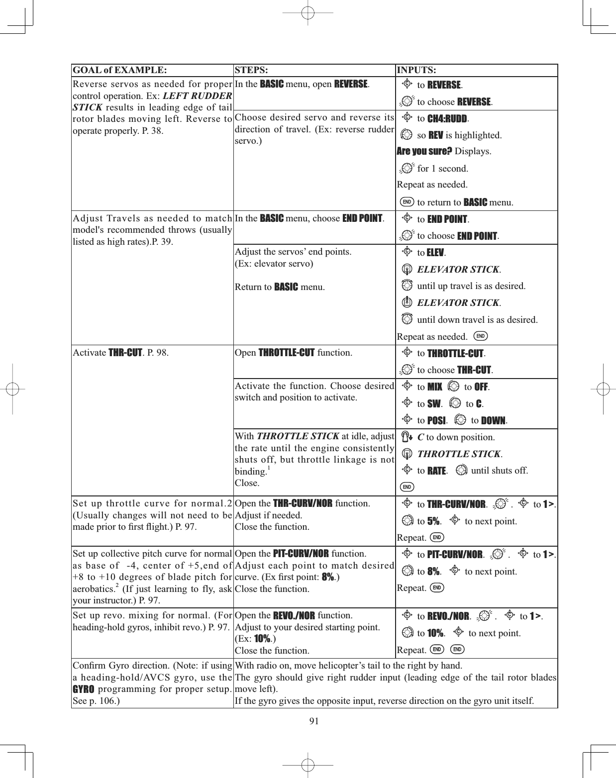
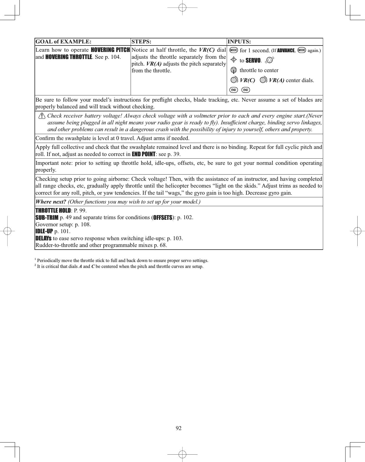
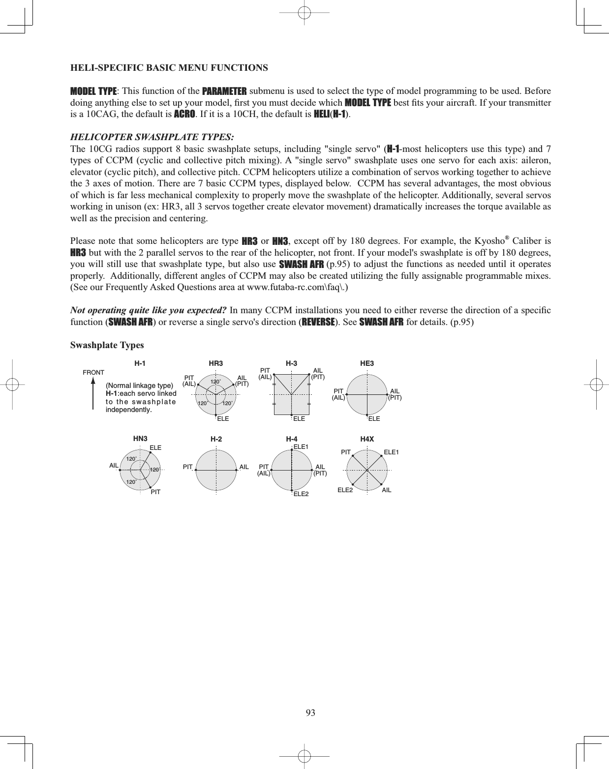
![94GOAL of EXAMPLE: STEPS: INPUTS:Change the MODEL TYPE and SWASH TYPE of model #3 from aircraft to 120degree CCPM with 2 servos working in unison for collective pitch and aileron [HELI(HR3)].Confirm you are currently using the proper model memory. (example: 3)On home screen, check model name and # on top left.If it is not the correct model (example:3), see MODEL SELECT, p. 25.Open PARAMETER submenu. for 1 second. (If ADVANCE, again.)to 2nd page of menu.Cto PARAMETER.Select proper MODEL TYPE.(HELICOPTER)&RQ¿UPWKHFKDQJHCto TYPE.to HELICOPTER. for 1 second.Are you sure? displays. WRFRQ¿UP1Change to the desired SWASH TYPE (example, HR3.) &RQ¿UPWKHFKDQJHCto SWASH.to HR3. for 1 second.Are you sure? displays. WRFRQ¿UPClose.Where next? If a single servo is not operating properly, REVERSE: see p. 38.If a control is operating backwards (i.e. Elevator), see SWASH AFR, p. 95.If unsure see SWASH AFR.1Radio emits a repeating “beep” and shows progress on screen as the model type is being changed. Note that if the power switch is turned off prior to completion, the model type will not be changed.](https://usermanual.wiki/Futaba/T10CG-24G/User-Guide-1093539-Page-94.png)
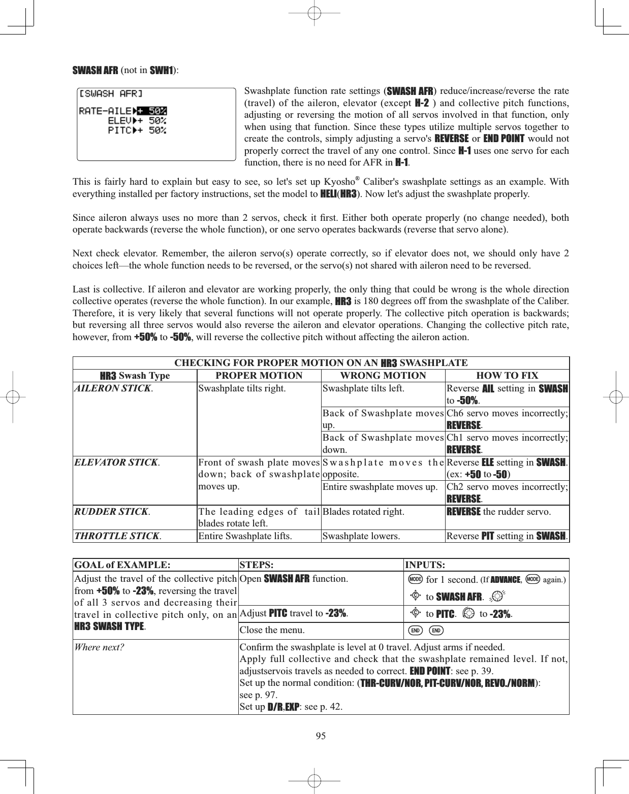
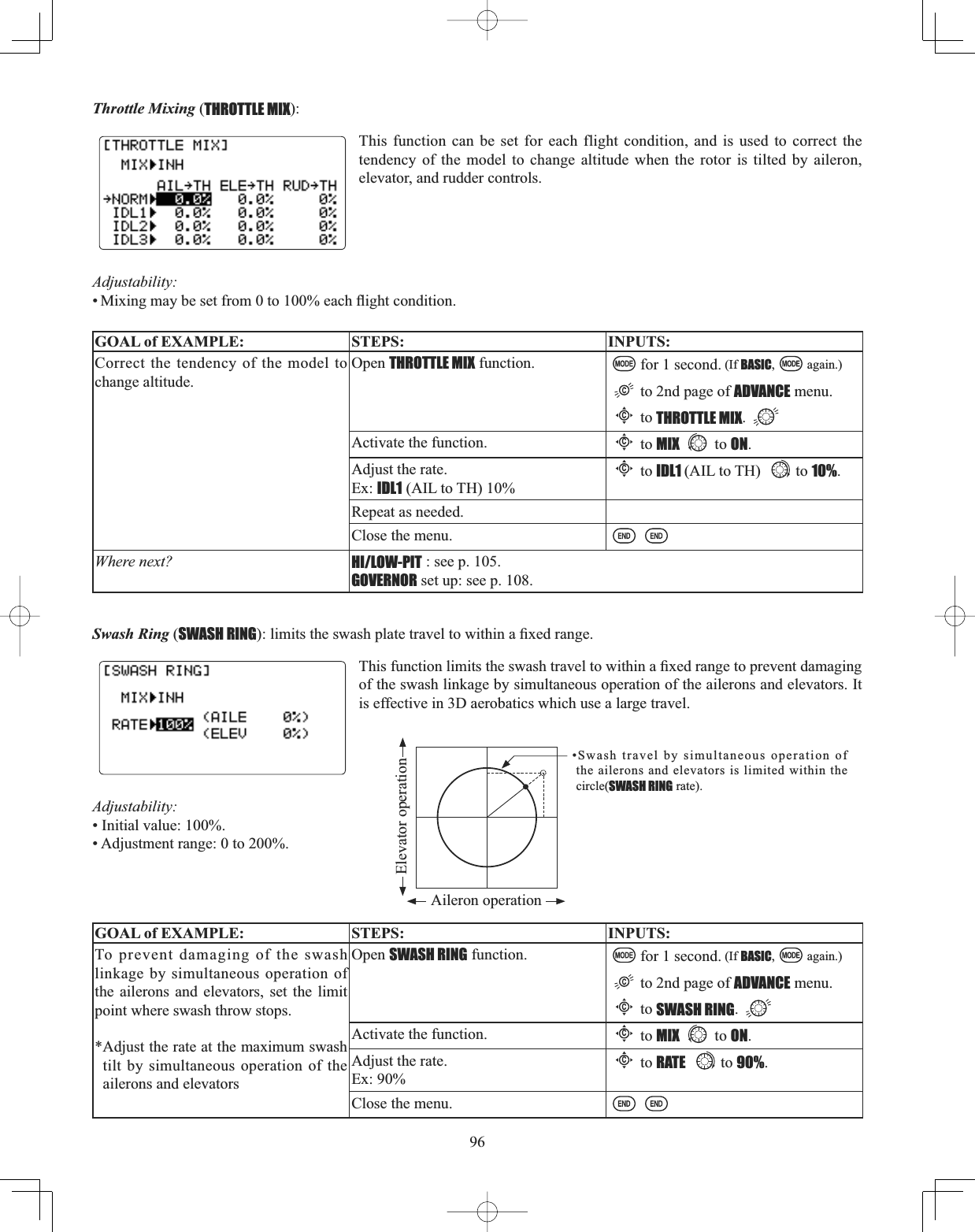
![97Setting up the Normal Flight Condition:7KH1RUPDOÀLJKWFRQGLWLRQLVW\SLFDOO\XWLOL]HGIRUKRYHULQJ7KHWKURWWOHDQGFROOHFWLYHSLWFKFXUYHVDUHDGMXVWHGWRSURYLGHFRQVLVWHQWHQJLQH530GHVSLWHWKHLQFUHDVHGHFUHDVHLQFROOHFWLYHSLWFKRIthe blades. This keeps the engine from “bogging down” under excessive load (like trying to accelerate a car on a steep hill LQWKJHDURUH[FHVVLYH530XQGHULQVXI¿FLHQWORDGOLNHÀRRULQJWKHWKURWWOHZKLOHLQQHXWUDOULVNLQJHQJLQHGDPDJH$VWKHFXUYHVDQGUHYRPL[LQJDUHDOOLQWHUUHODWHGZHZLOOGLVFXVVDOOWKUHH¿UVWWKHQFRPSOHWHDVDPSOHVHWXSNote that the normal throttle, pitch and revo curves are all available in the BASIC menu for simplicity. These may also be updated later in the ADVANCE menu with the settings for the other 4 conditions [idle-up 1 (IDL1), idle-up 2 (IDL2) and idle-up 3 (IDL3), plus throttle hold (HOLD)]. Note: The throttle and pitch curves for the normal condition are always on. They cannot be inhibited. The other four conditions are activated with their throttle curves or throttle hold. For idle-ups, see p. 90. For throttle hold, see p. 99. •THR-CURV/NOR: inputs the normal (NORM) throttle curve, which is usually not a linear response to THROTTLE STICKmotion. Adjusting point 4 of the curve adjusts the engine’s RPM at the THROTTLE STICK midpoint . the desired position for hovering. The other 6 points are then adjusted to create the desired idle and maximum engine speed, and a smooth transition in-between. For more on throttle curves, see p. 101. •PIT-CURV/NOR: inputs the normal (NORM) collective pitch curve, the collective pitch curve for flight near hover. The normal collective pitch curve is adjusted to match the throttle curve, providing the best vertical performance at a constant engine speed, with a starting curve of .4 base, +5 neutral, and +8 to +10 degrees of blade pitch maximum*. You can program the response over a 7-point curve for the best collective pitch angle relative to THROTTLE STICK movement. For more on collective pitch curves, see p. 101. •REVO./NORM: mixes collective pitch commands to the rudder (a PITCH-RUDDER mix) to suppress the torque generated by changes in the main rotor's collective pitch angle, keeping the model from yawing when throttle is applied. REVO. is H[WUHPHO\KHOSIXOLQ³WDPLQJWKHWDLO´RIPRGHOVQRWXVLQJKHDGLQJKROGAVCS gyros. NOTE: There are three revo. mixes available: normal (NORMLGOHXSIDL1/2), and idle-up 3 (IDL3). All 3 are adjustable in the ADVANCEPHQX1HYHUXVHUHYRPL[LQJLQFRQMXQFWLRQZLWKKHDGLQJKROG$9&6J\URV)RUGHWDLOVRQrevo, including default points for clockwise and counterclockwise rotating rotors, see p. 101. 7KHVH GHIDXOW UHFRPPHQGDWLRQV DVVXPH \RX DUH GRLQJ IRUZDUG ÀLJKW ,I \RX DUH MXVW OHDUQLQJ SOHDVH IROORZ \RXU LQVWUXFWRU¶V JXLGDQFH 6RPHLQVWUXFWRUVOLNHDEDVHSRLQWIRUWUDLQLQJVRWKDWWKHKHOLFRSWHUFRPHVGRZQYHU\VORZO\HYHQLI\RXULQVWLQFWVSXOOWKHWKURWWOHFROOHFWLYHVWLFNWRthe bottom in a hurry.](https://usermanual.wiki/Futaba/T10CG-24G/User-Guide-1093539-Page-97.png)
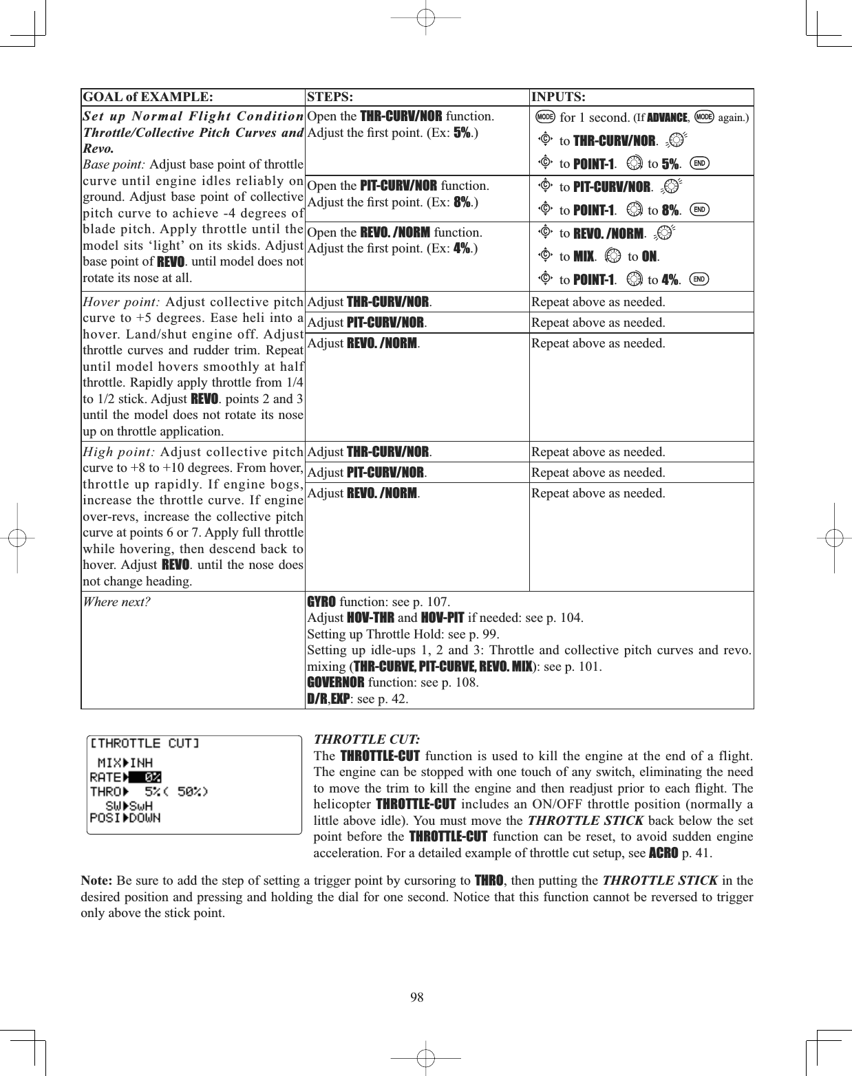
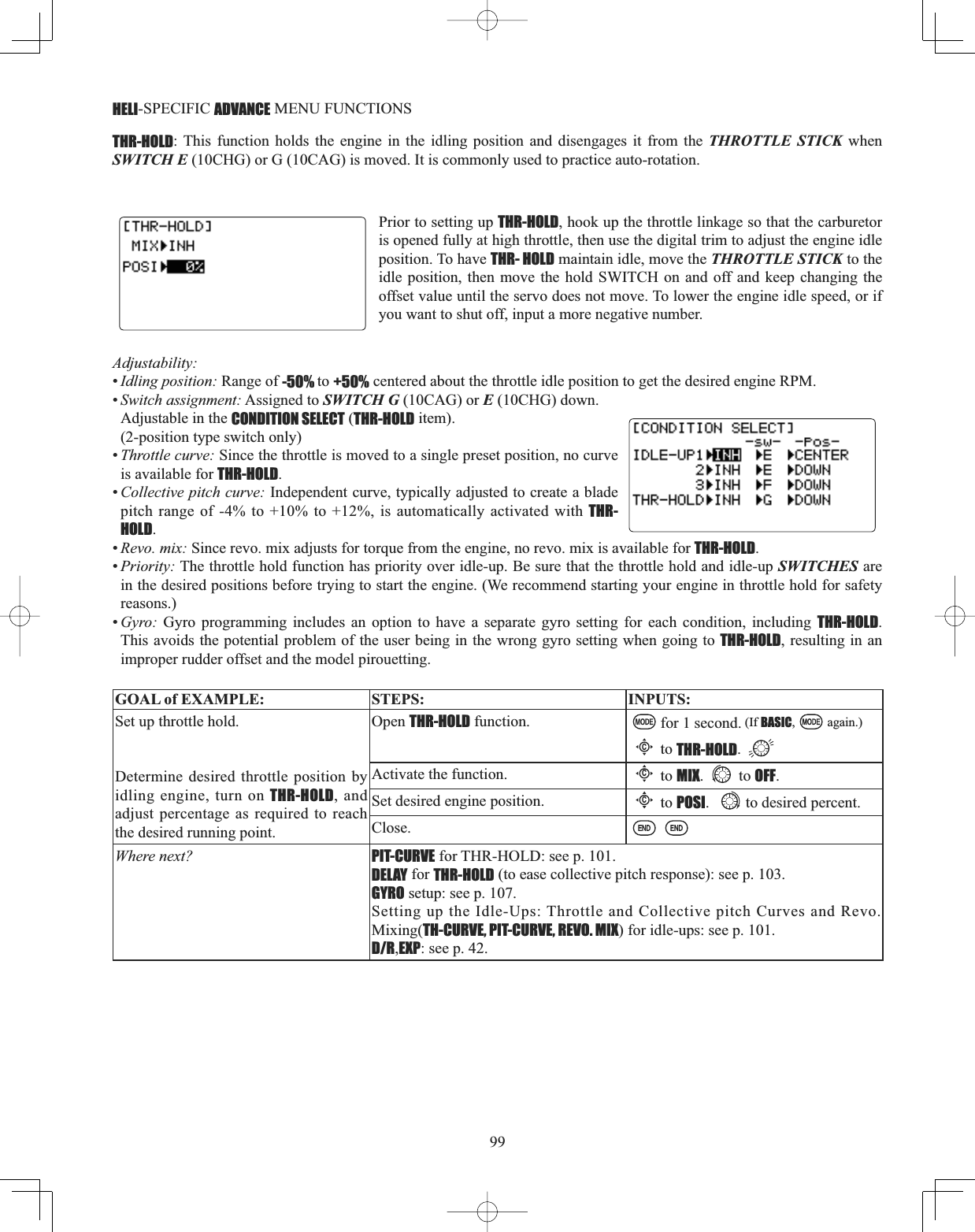
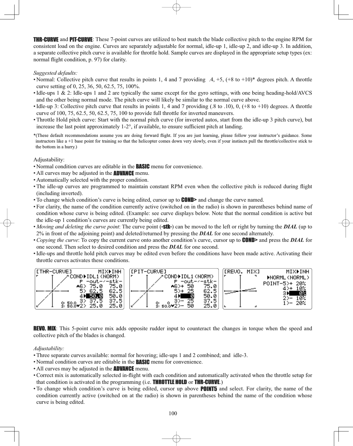
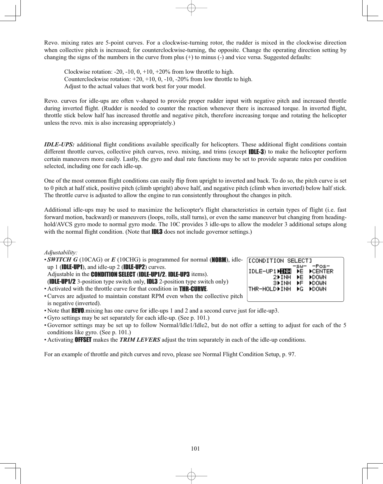
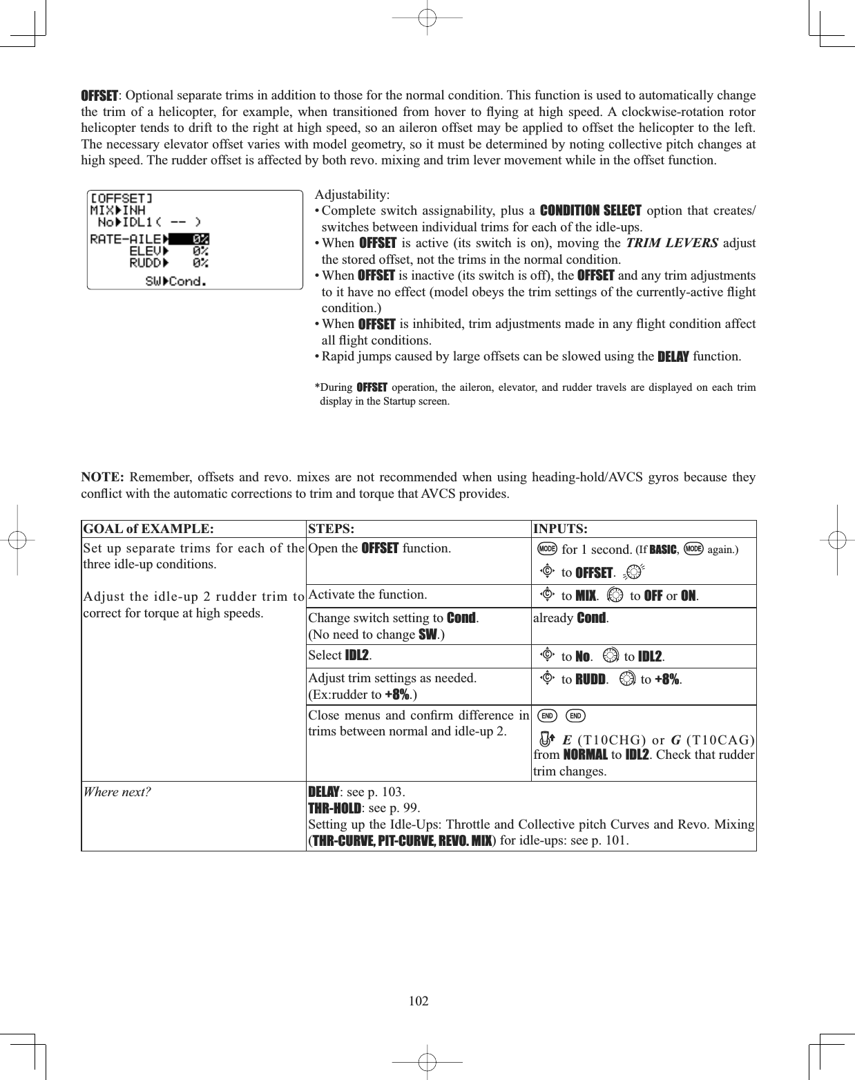
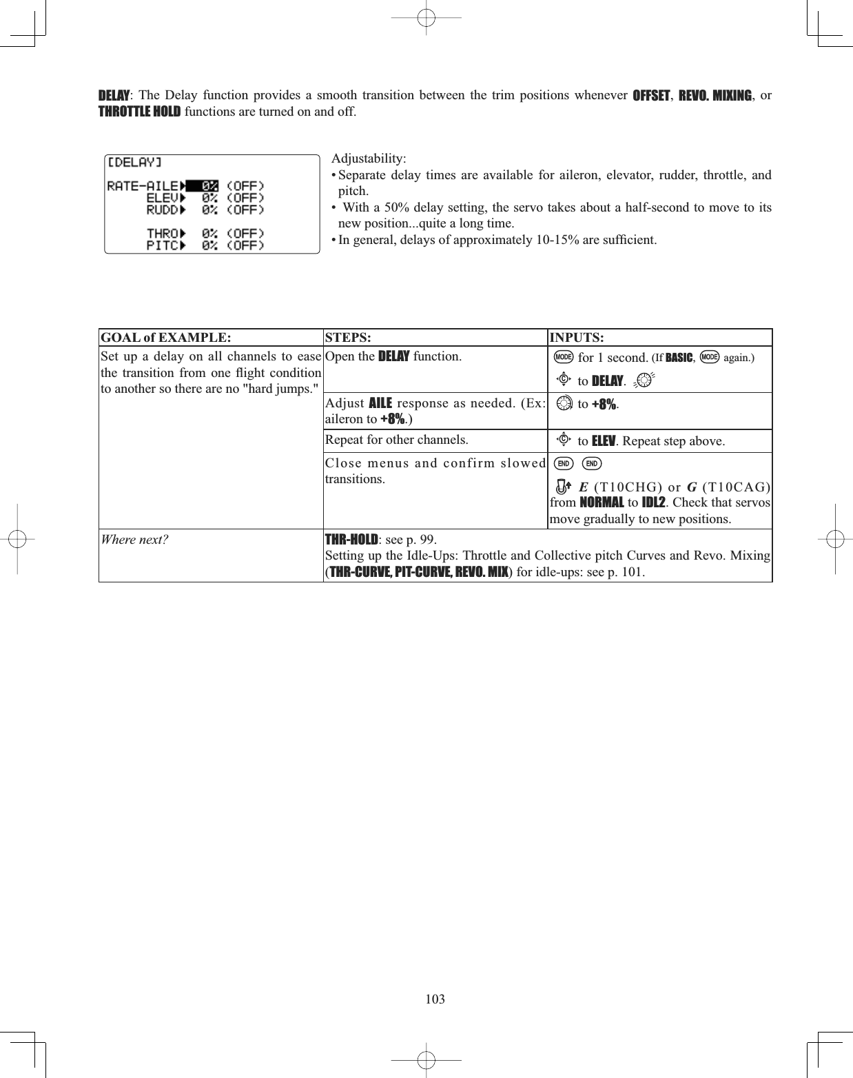
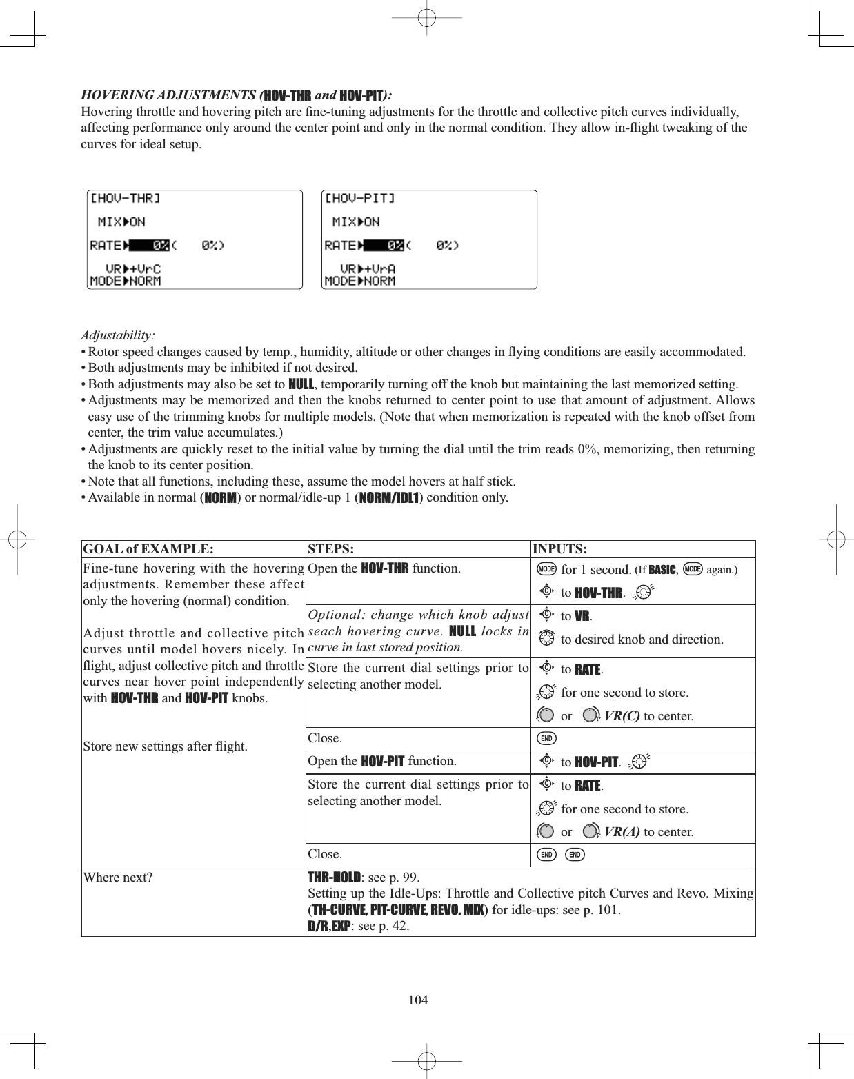
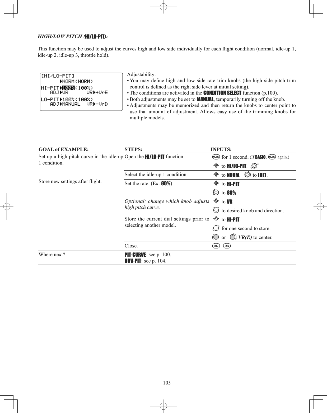
![106*<526DQG*29(512568VLQJHOHFWURQLFVWRWDNHVRPHRIWKHFRPSOH[LW\RXWRIVHWXSVDQGÀLJKWWhat is a gyro? A gyroscope is an electronic unit that senses motion and corrects for it. For example, if the wind blows \RXUKHOLFRSWHU¶VWDLOWRWKHOHIWDJ\URZLOOVHQVHWKDWPRWLRQDQGFRQ¿UPWKDWQRLQSXWZDVJLYHQDQGZLOOFRUUHFWIRULWHow does it help in helicopter setup? A good gyro will totally eliminate the need for revo. mixing. The gyro will sense and correct the unwanted motion for you, so you don’t have to spend time to get a complex curve operating properly. Gyro sensor kinds: There are many different kinds of gyros. Early gyros were mechanical, with a spinning drum similar to a child’s gyroscope toy. The next generation utilized a special type of crystal, called piezoelectric, which sensed the motion DQGSURYLGHGDQHOHFWULFDOSXOVH7KH¿QHVWJ\URVDWWKHWLPHRIWKLVZULWLQJDUH600WHFKQRORJ\7KHVHVLOLFRQHPLFURmachines, or computer chips, sense the motion. SMM is far more accurate and less susceptible to inaccuracies caused by temperature changes, etc. Types of gyro responses: • Normal: sense motion and dampen it (if the gyro rotates off course for 2 seconds, it corrects for 2 seconds). +HDGLQJKROG$9&6 FDOFXODWH WKH DQJOH RI URWDWLRQ E\ WUDFNLQJ WKH WLPHUDWH RI FKDQJH DQG WKHQ SURYLGH FRUUHFWLRQuntil the same rotation is achieved. • Stick priority: a feature on most high-end gyros. The more input given on the channel the gyro controls, the less sensitive the gain is automatically. This way, if you give a large input for a stall turn, for example, the gyro turns itself off and GRHVQRW¿JKWWKHVWDOOWXUQ$V\RXHDVHRIIWKHUXGGHUWKHJDLQLQFUHDVHVDJDLQPLQLPL]LQJWDLOZDJDQGNHHSLQJWKHmodel straight. (If your gyro does not include stick priority, you can manually create it. Please see www.futaba-rc.com\faq\.)Choosing the right gyro for your skills, your helicopter, and your budget: • Mechanical: some are still available. They are very challenging to set up and not as reliable as piezo or SMM. • Non-Heading-Hold Piezo: these are now inexpensive gyros that are reliable and easy to set up. Some have dual rates and UHPRWHJDLQFRQWUROWRDGMXVWVHQVLWLYLW\LQÀLJKW/DFNKHDGLQJKROGFDSDELOLWLHVIRUSUHFLVLRQÀ\LQJ• Heading-Hold Piezo: Until recently, the cream of the crop. Expensive, and more complex to set up. Adds GPS-like KHDGLQJUHFRJQLWLRQ([KLELWVPLQRUGLI¿FXOWLHVZLWKWHPSHUDWXUHGULIWSRVLWLRQVHWWLQJYDU\LQJZLWKXQLW¶VWHPSHUDWXUH• Heading-Hold SMM: 21st Century gyro technology. Computer chip technology. Expensive, easier set up, higher GXUDELOLW\6LJQL¿FDQWGHFUHDVHLQWHPSHUDWXUHVHQVLWLYLW\0DQ\LQFOXGHIUDPHUDWHVHWWLQJVWRDOORZIDVWHUUHVSRQVHZKHQusing specialized digital servos. Examples: • GY401: Simpler set up. Ideal for learning aerobatics through 3D. • GY502: Better centering than 401 for more advanced aerobatics. Ideal through Class III competition. • GY611: Exceptional center. Extremely fast response time. Requires specialized servo. GYROVLPSOL¿HVDGMXVWLQJVHOHFWLQJWKHJ\URVHQVLWLYLW\DQGFDQSURYLGHPRUHWKDQJ\URJDLQVHWWLQJV7KHKLJKHUWKHgain, the more correction the gyro provides and the “softer” or less responsive the helicopter feels.) This function makes WKHEHVWSRVVLEOHXVHRIWKHLQÀLJKWDGMXVWDEOHJDLQRIPRVWJ\URVAdjustability:• Plug the gyro’s sensitivity adjustment to channel 5 of the receiver. (not assignable) •STDDQG$9&6+HDGLQJKROGGYVHWXSW\SHVDYDLODEOHWRVLPSOLI\DGMXVWPHQWVIRU$9&6+HDGLQJKROGJ\URV• Full switch assignability or may select Cond. option. •Cond. option provides separate gyro settings, one for each condition, automatically selected with the condition. Allows FKDQJHVLQJDLQWRPHHWWKHVSHFL¿FQHHGVRIHDFKÀLJKWFRQGLWLRQ• Each gyro setting may be set from 0 to +100 (NOR100% to AVC100%) gain, equating to ATV settings of -100% to +100%. 'XDOPRGHJ\URVKHDGLQJKROG$9&6DQGQRUPDODUHHDVLO\WULJJHUHGWRHDFKPRGHE\FKDQJLQJWKHJ\URVHWWLQJ¶VVLJQNegative settings trigger normal mode; positive settings are AVCS mode. • Larger percentages indicate more gain, or gyro responsiveness. • Tail wagging or shaking indicates excessive gain settings. Turn down gyro setting until wag stops.](https://usermanual.wiki/Futaba/T10CG-24G/User-Guide-1093539-Page-106.png)
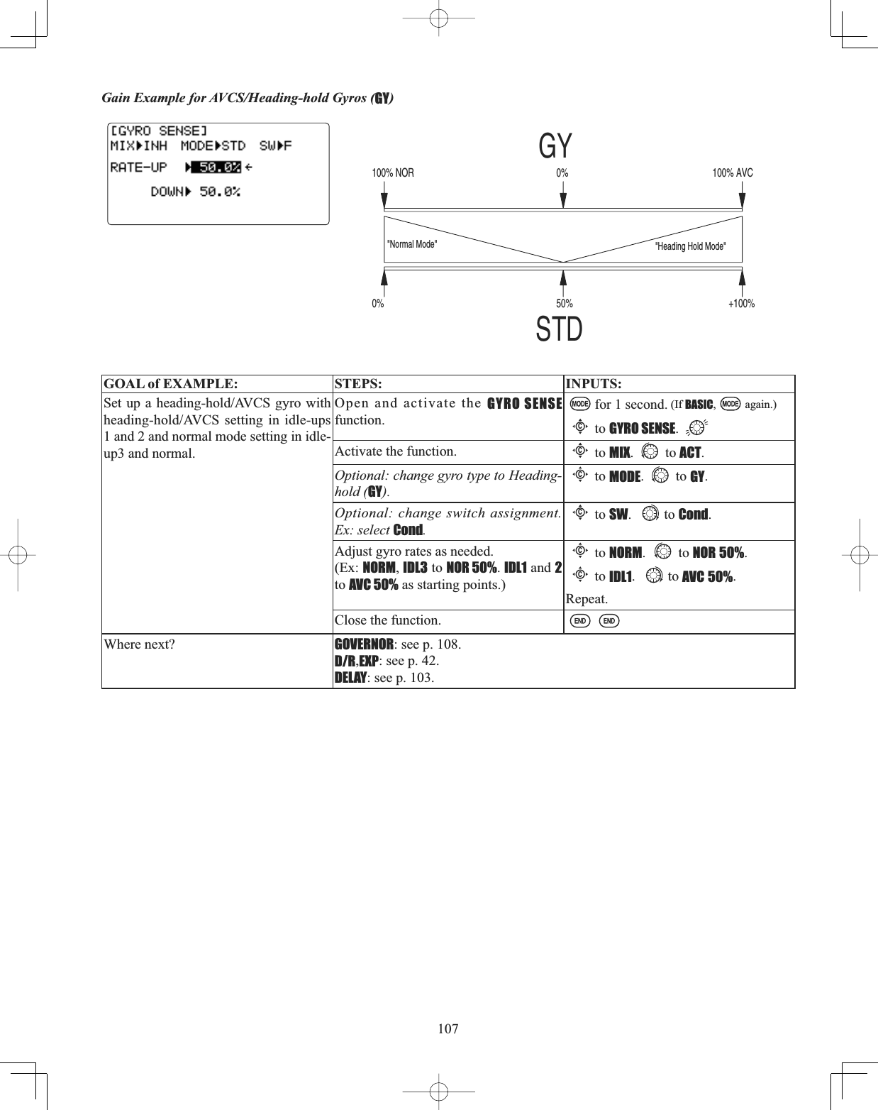
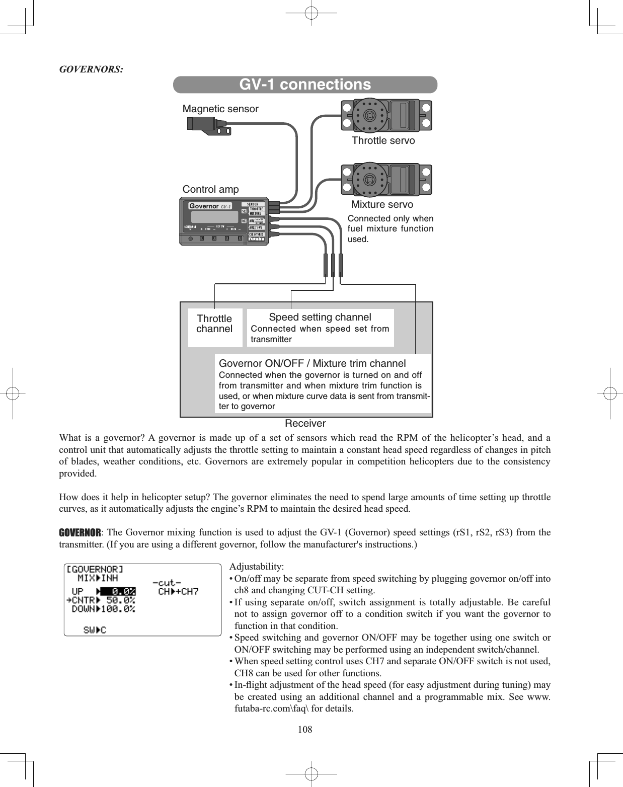
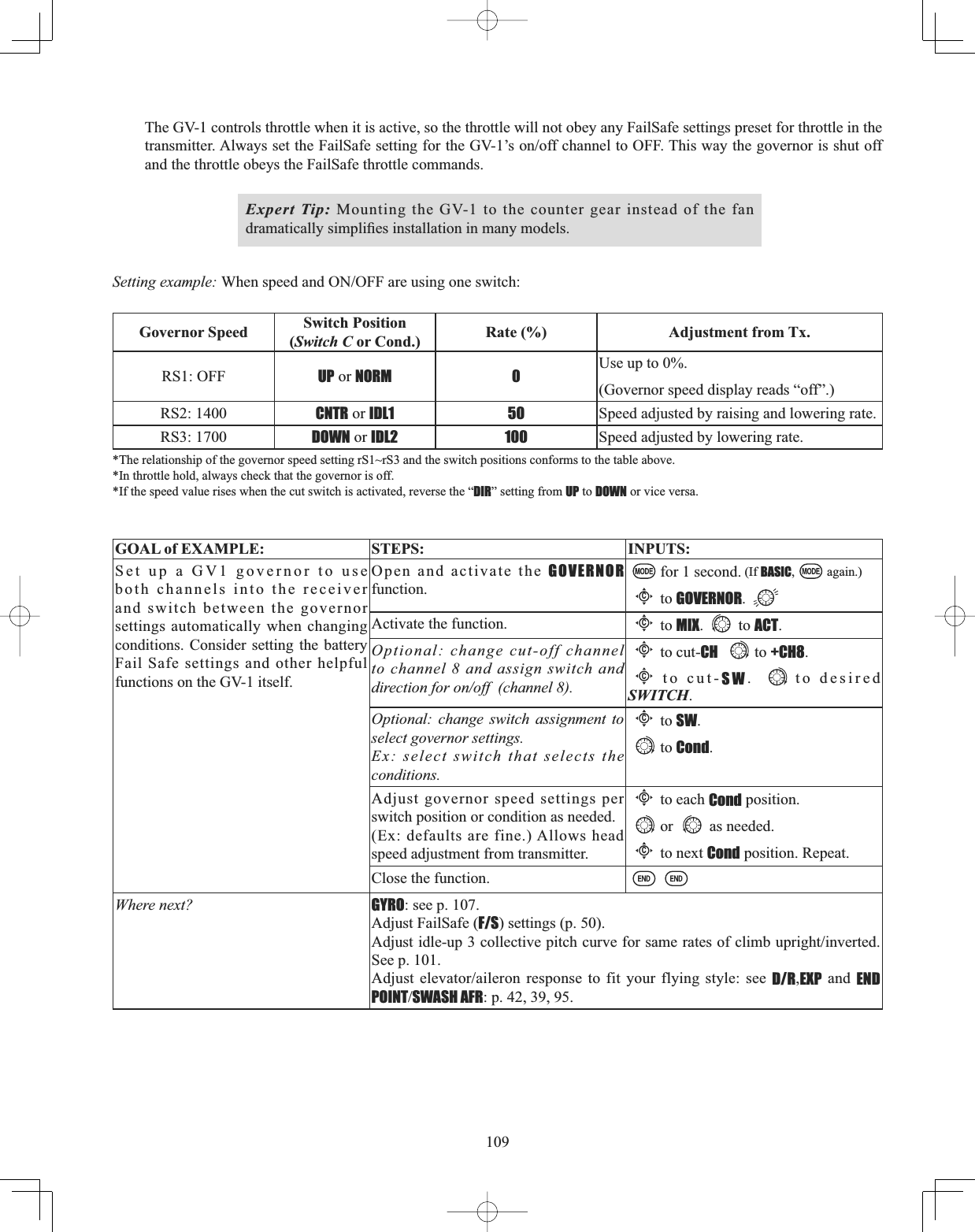
![111triggered by THROTTLE STICK POSITION. For similar glider programming, see BUTTERFLY. ...................................... 63 $0$$FDGHP\RI0RGHO$HURQDXWLFV1RQSUR¿WRUJDQL]DWLRQJRYHUQLQJPRGHODLUFUDIWÀLJKWLQWKH86...................... 5 AST: Adjustable Servo Travel. See END POINT.ATL: Adjustable Travel Limited. Standard type of trim used for throttle, where the trim is effective only in the idle portion of the THROTTLE STICK POSITION. Normal trims affect the entire travel of the servo (ex: elevator trims), but ATLtrims only the low end of the throttle movement, allowing throttle idle adjustments that donit over-drive the servo at full throttle. ................................................................................................................................................................................. 38ATV: Older, less clear terminology for end point adjustment. See END POINT.Autorotation: The ability of a helicopter to land safely without engine power, using the stored energy in the bladeis rotation WRSURGXFHOLIWIRUÀDULQJAUX-CH: Auxiliary channel setup. Used to assign which KNOBSSWITCHESSLIDERS control channels 5-9. Includes CH9 servo reverse. Also allows assignment of a channel to mixing only (assigned as NULL), with no primary control. .... 46 Backup battery: battery used to protect data storage in case of removal of master transmitter battery. In most Futaba radios, including the 10CG, EEPROM data storage is used, so no backup battery is used or needed. BACKUP ERROR: transmitter's hard-coded memory has been lost. Send for service immediately. ....................................... 24Base-Loaded antenna: also called Whip antenna. Aftermarket equipment not approved by Futaba. Basic model setups: guidelines to setting up the most basic models of each type. ........................ ACRO 27 GLID 76 HELI 90 BASICPHQXV6SHFL¿FPHQXVZLWKPRVWFRPPRQO\XVHGIHDWXUHVIRUHDFKPRGHOW\SH .............. ACRO 30 GLID 78 HELI 93 Battery care and charging. (Charging the Ni-Cd batteries) ................................................................................................. 15 Battery FailSafe: determines how the receiver indicates an airborne pack low-battery warning. Defaults: 56% throttle, requires throttle to idle to override. To adjust the warning point, set a THROTTLE STICK POSITION in F/S. .............. 50 BEEP: tone emitted by transmitter to signify a variety of situations. See Error messages.Binding: friction in a joint exceeding the movement of the linkage. Sticking or inability to continue movement. The servo FRQWLQXHVWRDWWHPSWWRPRYHWKHVXUIDFHEH\RQGLWVSRZHUFDSDELOLWLHVUDSLGO\GUDLQLQJEDWWHU\SRZHUDVLWFRQWLQXHVWRstruggle.%UDNHÀDSPL[LQJGLID7KUHHPL[HVEUDNHÀDSWRHOHYDWRUWRDLOHURQDQGWRVSHHGÀDSVFRPSHQVDWHIRUXQZDQWHGreaction to lowering the brake flap, 2) increase brake flap area by including the flaperons, and 3) add lift to increase maneuverability. Not a preprogrammed mix. See Programmable mix.Buddy Box: see Trainer box. BUTTERFLY: (GLID) [also called crow, AIRBRAKE(ACRO@$FWLYDWHV XS ÀDSHURQV DQG GRZQ ÀDSV IRU JOLGLQJ VSHHG FRQWUROwithout spoilers or airbrakes. Note: More adjustable programming is available in ACRO,AIRBRAKE. ................................ 63 CAMBER FLAP (GLIDDVVLJQVWKHSULPDU\ÀDSFRQWUROWRDOORZWULPPLQJLQÀLJKWRIWKHÀDSDFWLRQ7KHXSGRZQWUDYHORIHDFKÀDSFDQEHDGMXVWHGLQGHSHQGHQWO\$OVRWKHFHQWHUSRVLWLRQRIÀDSVHUYRFDQEHRIIVHW........................................... 86CAMBER MIX (GLIDDGMXVWVWKHPL[LQJUDWHRIFDPEHURSHUDWLRQZKLFKRSHUDWHVWKHZLQJFDPEHUDLOHURQVDQGÀDSVLQWKHQHJDWLYHDQGSRVLWLYHGLUHFWLRQV7KHDLOHURQÀDSDQGHOHYDWRUUDWHVFDQDOVREHDGMXVWHGLQGHSHQGHQWO\DQGDWWLWXGHchanges caused by camber operation can be corrected. ....................................................................................................... 85CAMPac2SWLRQDOH[WHQGHGGDWDVWRUDJHPRGXOH)XWDEDVWRFN'3....................................................... 10 CCPM: Cyclic (pitch and roll) Collective Pitch Mixing. Multiple servos work in unison on the helicopteris head to create one or more of the control functions. Ex: 3 servos set at 120 degrees operate the entire head. The 2 forward servos work together to rotate both the blade's pitch and the roll cyclic (aileron) in a HR3 head type. See MODEL TYPE,HELI.CH5&6: setting in AILE-2 that allows the second aileron servo to be in channel 5. See Twin aileron servos.CH6 or 7: default setting in AILE-2. Second aileron servo is in channel 6 or 7 depending on function used. See Twin aileron](https://usermanual.wiki/Futaba/T10CG-24G/User-Guide-1093539-Page-111.png)
![116NiMH: Nickel Metal Hydride rechargeable battery. Newer battery technology than Ni-Cd. Longer run times but more VSHFL¿FSHDNFKDUJLQJUHTXLUHPHQWV>5HTXLUHD]HURGHOWDSHDNFKDUJHUODEHOHGVSHFL¿FDOO\IRUXVHZLWK1L0+EDWWHULHV@NORMAL: trainer mode that does not give student radio the computer programming features of the master radio. See Trainer.NT8S: standard transmitter battery pack. See Accessories.NULL: not assigned or never changed. Ex: a mix which has a null switch assignment is always active, and can never be FKDQJHGLQÀLJKWWXUQHGRIIQRPDWWHUZKLFKVZLWFKLVPRYHGOFFSET: (HELI) separate trim settings available to each idle-up (using CONDITION) setting, or assigned to separate switches from the condition switches. When offset is ON, movement of the trim levers adjusts the OFFSET, not the normal condition's trims. .................................................................................................................................................................................. 102OFFSETsDGGLWLRQDOÀLJKWFRQGLWLRQVDYDLODEOHVSHFLI¿FDOO\IRUVDLOSODQHV ......................................................................... 84Offset mix: mix that independently moves the slave servo a set percentage of its total throw, not in relation to any master. See Programmable mix.PA2: Pilot Assist. Optional onboard device that uses optical sensors to correct modelis orientation to upright.PARAMETERVXEPHQXVHWVVSHFL¿FSDUDPHWHUV,QFOXGHVUHVHWW\SHPRGXODWLRQVHFRQGDLOHURQVHUYRVHWXSDQGATL. ... 33 Peak Charger: charger that automatically stops charging when the battery is fully charged (commonly called ipeakedi). See Battery care and charging.Piezo gyro: gyro that uses a piezo crystal to sense angular changes. See Gyros and Governors.Pitch-to-rudder mix: see REVO.PITCH CURVE: (HELI FXUYH WKDW VHWV WKH UHVSRQVH RI WKH FROOHFWLYH SLWFK VHUYRV WR PRYHPHQW RI WKH WKURWWOHFROOHFWLYHSTICK ,QGHSHQGHQWO\ DGMXVWDEOH LQ WKH QRUPDO ÀLJKW PRGH RQH IRU HDFK RI WKH LGOHXSV DQG RQH IRU WKURWWOH KROGAdjusted to provide ideal blade response for various types of maneuvers being performed. For simplicity, the normal condition's curve may be set in the BASIC menu. All 5 curves are also adjustable in the ADVANCE menu. ......................... 99 PPM: Pulse Position Modulation. Type of signal transmission. Programmable mix: used to cause specific servo responses to specific inputs separate from the basic control setups. ,QFOXGHVH[WHQVLYHGH¿QLWLRQVRIW\SHVDQGH[DPSOHV ........................................................................................................ 68 5DQJHFKHFNRUWHVWWRWHVWWKHWUDQVPLWWHULVFRQWURORYHUWKHPRGHODWDVSHFL¿FGLVWDQFHDVDSUHFDXWLRQLQFKHFNLQJLWVSURSHURSHUDWLRQSULRUWRÀLJKW............................................................................................................................................ 18 Rate: amount of control given. Ex: see Programmable mix.RESET: to delete all data in the existing model only. User CANNOT erase all data in the radio. Only service center can do so. Part of PARAMETER submenu. ......................................................................................................................................... 33 5HWUDFWDEOHODQGLQJJHDUODQGLQJJHDUWKDWLVEURXJKWXSLQWRWKHPRGHOGXULQJÀLJKW ..................................................... 74 REVERSE: servo reversing. Used to reverse the direction of a servo to ease installation and set up. .................................... 38 Rudder-to-aileron mix: (ACROGLID) used to counteract undesirable roll (roll coupling) that happens with rudder input, especially in knife-edge. Gives proper aileron input to counteract roll coupling when rudder is applied. Not a preprogrammed mix. See Programmable mix. This is the default programming for one linear and one curve mix in ACROand GLID.Rudder-to-elevator mix: used to counteract undesirable pitch (pitch coupling) with rudder input, especially in knife edge ÀLJKW1RWDSUHSURJUDPPHGPL[6HHProgrammable mix. This is the default programming for one curve mix in ACRO.Rudder-to-throttle mix: (HELI) adds throttle to counter the added load from increasing pitch of the tail blades, maintaining a constant head-speed with rudder. (This is a minor effect and is not critical in most helicopters.) Not a preprogrammed mix.](https://usermanual.wiki/Futaba/T10CG-24G/User-Guide-1093539-Page-116.png)