Futaba T10CG-24G Radio Control(Transmitter) User Manual 10CG ENG 1M23N21005
Futaba Corporation Radio Control(Transmitter) 10CG ENG 1M23N21005
Futaba >
User manual
1
0
C
A
G/
10
C
H
G/
10
CG
-2.4
G
H
z
10-
C
HANNEL RADIO
C
ONTROL
S
Y
S
TEM
INSTRUCTION MANUAL
T
echnical updates and additional programming examples available at:
h
tt
p
://www.futaba-rc.com/fa
q
Entire
C
ontents
©C
opyright 200
9
1
M
23
N
2100
5

2
TABLE OF CONTENTS
INTRODUCTION ........................................................... 3
Additional Technical Help, Support and Service ........ 3
$SSOLFDWLRQ([SRUWDQG0RGL¿FDWLRQ ........................ 4
Meaning of Special Markings ..................................... 5
Safety Precautions (do not operate without reading) .. 5
Introduction to the 10CG ............................................ 7
&RQWHQWVDQG7HFKQLFDO6SHFL¿FDWLRQV........................ 9
Accessories ............................................................... 10
Transmitter Controls &
6ZLWFK,GHQWL¿FDWLRQ$VVLJQPHQWV ............................. 11
Charging the Ni-Cd Batteries ................................... 15
Stick Adjustments ..................................................... 16
Adjusting display contrast ........................................ 16
Changing mode.......................................................... 17
Power Down mode .................................................... 17
CAMPacLQLWLDOL]LQJDQGGDWDFRQYHUVLRQ&&6WR&*
.... 17
Radio Installation & Range Checking ...................... 18
Transmitter Displays and Buttons ............................. 23
Warning and Error Displays ..................................... 24
AIRPLANE (ACRO) FUNCTIONS ................................ 25
Map of Functions........................................................ 26
Quick Guide to Setting up a 4-channel Airplane ...... 27
ACRO BASIC MENU FUNCTIONS ................................ 30
MODEL Submenu: MODEL SELECT,COPY,NAME .......... 30
PARAMETER Submenu: RESET,TYPE,MODUL,ATL,AILE-2,THR-
REV,CONTRAST,BACK-LIGHT,HOME-DISP,USER NAME
........ 33
LOGIC SW
..................................................................... 38
Servo REVERSE ........................................................... 38
END POINT .................................................................. 39
Idle Management: IDLE DOWN and THR-CUT .............. 40
'XDO7ULSOH5DWHVDQG([SRQHQWLDOD/R,EXP) .......... 42
TIMER Submenu.......................................................... 45
Auxiliary Channel assignments and CH9 reverse (AUX-CH)
. 46
TRAINER ..................................................................... 47
TRIM and SUB-TRIM ................................................... 48
SERVO Display ........................................................... 49
Fail Safe and Battery FailSafe (F/S) ......................... 50
ACRO ADVANCE MENU FUNCTIONS ........................... 51
Wing types ................................................................ 51
FLAPERON ................................................................... 52
FLAP TRIM .................................................................. 53
Aileron Differential (AILE-DIFF) ................................. 54
Using Twin Aileron Servos: AILE-2 ........................... 55
ELEVON (see tail types) ............................................... 56
Tail types ................................................................... 56
ELEVON ....................................................................... 56
Twin Elevator Servos (AILEVATOR) ............................ 57
V-TAIL ......................................................................... 58
SNAP ROLL .................................................................. 59
0L[HVGH¿QLWLRQVDQGW\SHV ..................................... 61
ELEV-FLAP .................................................................... 62
AIRBRAKEBUTTERFLY (crow) ..................................... 63
THROTTLE-NEEDLE ........................................................ 65
THROTTLE DELAY ......................................................... 66
THROTTLE CURVE ........................................................ 67
Linear, Prog. mixes 1-4 ............................................. 68
Curve, Prog. mixes 5-8 ............................................. 71
GYA gyro mixing (GYRO SENSE) ............................... 73
Other Equipment ....................................................... 74
GLIDER (GLID(1A+1F)(2A+1F)(2A+2F)) FUNCTIONS . 75
Table of contents........................................................ 75
Getting Started with a Basic 4-CH Glider ................ 76
GLIDER-SPECIFIC BASIC MENU FUNCTIONS ........ 78
Model type (PARAMETER submenu) ........................... 78
MOTOR CUT ................................................................ 79
GLIDER-SPECIFIC ADVANCE MENU FUNCTIONS
..... 80
AILE/RUDD .................................................................. 81
AILE-FLAP (GLID(2A+2F) only) .................................... 82
SPOILER MIX ............................................................... 83
OFFSETs$GGLWLRQDOÀLJKWFRQGLWLRQV...................... 84
START DELAY (GLID(1A+1F) only) ................................. 85
CAMBER MIX ............................................................... 85
CAMBER FLAP .............................................................. 86
BUTTERFLY................................................................... 87
Channel 3’s function selection (CONDITION/FUNCTION)
88
HELICOPTER FUNCTIONS.......................................... 89
Table of contents and reference info for helicopters . 89
Getting Started with a Basic Helicopter ................... 90
HELI-SPECIFIC BASIC MENU FUNCTIONS ................ 93
MODEL TYPE (PARAMETERS submenu) ........................ 93
SWASH AFR (swashplate surface direction and travel
correction) (not in H-1) .............................................. 95
Setting up the Normal Flight Condition ................... 97
THR-CUTVSHFLDOL]HGVHWWLQJVIRUKHOLFRSWHUVSHFL¿F
models) ..................................................................... 98
HELI-SPECIFIC ADVANCE MENU FUNCTIONS ........... 99
THROTTLE HOLD .......................................................... 99
THR-CURVE,PIT-CURVE and REVO ............................. 100
Idle-ups ................................................................... 101
7ULPVRIIVHW............................................................. 102
Delay ....................................................................... 103
Hovering setups ...................................................... 104
+LJKORZSLWFK ........................................................ 105
Gyros and governors ............................................... 106
THROTTLE MIX ............................................................ 96
SWASH RING .............................................................. 96
Glossary ........................................................................ 110
Note that in the text of this manual, beginning at this
point, any time we are using a feature’s specialized name
or abbreviation, as seen on the screen of the 10C, that
name, feature, or abbreviation will be exactly as seen on
the radio’s screen, including capitalization and shown in
aDIFFERENT TYPE STYLE for clarity. Any time we mention
a specific control on the radio itself, such as moving
SWITCH A,KNOB VR(B), or the THROTTLE STICK,
those words will be displayed as they are here.
3
INTRODUCTION
Thank you for purchasing a Futaba® FASST-2.4GHz*&* VHULHVGLJLWDOSURSRUWLRQDO5&V\VWHP7KLVV\VWHPLV
extremely versatile and may be used by beginners and pros alike. In order for you to make the best use of your system
DQGWRÀ\VDIHO\SOHDVHUHDGWKLVPDQXDOFDUHIXOO\,I\RXKDYHDQ\GLI¿FXOWLHVZKLOHXVLQJ\RXUV\VWHPSOHDVHFRQVXOWWKH
manual, our online Frequently Asked Questions (on the web pages referenced below), your hobby dealer, or the Futaba
Service Center.
*FASST: Futaba Advanced Spread Spectrum Technology
Owner’s Manual and Additional Technical Help
This manual has been carefully written to be as helpful to you, the new owner, as possible. There are many pages of
setup procedures and examples. However, it need not be your sole resource of setup guidelines for your 10CG. For
example, pages 27-29 include setup instructions for a basic 4-channel airplane. The Frequently Asked Questions web page
referenced below includes this type of step-by-step setup instructions for a variety of other model types, including multi-
engine, complex gear installation, 7-servo aerobatic models, 140 degree CCPM, etc.
KWWSZZZIXWDEDUFFRPIDT
Due to unforeseen changes in production procedures, the information contained in this manual is subject to change without
notice.
Support and Service: It is recommended to have your Futaba equipment serviced annually during your hobby’s “off
season” to ensure safe operation.
IN NORTH AMERICA
Please feel free to contact the Futaba Service Center for assistance in operation, use and programming. Please be sure to
UHJXODUO\YLVLW WKH &* )UHTXHQWO\$VNHG4XHVWLRQVZHEVLWHDWZZZIXWDEDUFFRPIDT7KLV SDJH LQFOXGHV H[WHQVLYH
programming, use, set up and safety information on the 10CG radio system and is updated regularly. Any technical
XSGDWHVDQG86PDQXDOFRUUHFWLRQVZLOOEHDYDLODEOHRQWKLVZHESDJH,I\RXGRQRW¿QGWKHDQVZHUVWR\RXUTXHVWLRQV
there, please see the end of our F.A.Q. area for information on contacting us via email for the most rapid and convenient
response.
Don’t have Internet access? Internet access is available at no charge at most public libraries, schools, and other public
UHVRXUFHV:H¿QGLQWHUQHWVXSSRUWWREHDIDEXORXVUHIHUHQFH IRUPDQ\PRGHOHUV DVLWHPVFDQ EHSULQWHGDQGVDYHGIRU
future reference, and can be accessed at any hour of the day, night, weekend or holiday. If you do not wish to access the
internet for information, however, don’t worry. Our support teams are available Monday through Friday 8-5 Central time
to assist you.
FOR SERVICE ONLY:
Futaba Service Center
3002 N. Apollo Drive, Suite 1
Champaign, IL 61822
Phone: 217-398-0007
ZZZIXWDEDUFFRPVHUYLFHKWPO
Email: service@futaba-rc.com
FOR SUPPORT :
(PROGRAMMING AND USER QUESTIONS)
Please start here for answers to most questions:
ZZZIXWDEDUFFRPIDT
FACSIMILE: 217-398-7721
PHONE: 217-398-8970 option 2
OUTSIDE NORTH AMERICA
Please contact your Futaba importer in your region of the world to assist you with any questions, problems or service
needs.
Please recognize that all information in this manual, and all support availability, is based upon the systems sold in North
America only. Products purchased elsewhere may vary. Always contact your region’s support center for assistance.

4
$SSOLFDWLRQ([SRUWDQG0RGL¿FDWLRQ
1. This product may be used for model airplane or surface (boat, car, robot) use. It is not intended for use in any application
other than the control of models for hobby and recreational purposes. The product is subject to regulations of the Ministry
RI5DGLR7HOHFRPPXQLFDWLRQVDQGLVUHVWULFWHGXQGHU-DSDQHVHODZWRVXFKSXUSRVHV
2. Exportation precautions:
(a) When this product is exported from the country of manufacture, its use is to be approved by the laws governing
the country of destination which govern devices that emit radio frequencies. If this product is then re-exported to other
countries, it may be subject to restrictions on such export. Prior approval of the appropriate government authorities may
be required. If you have purchased this product from an exporter outside your country, and not the authorized Futaba
distributor in your country, please contact the seller immediately to determine if such export regulations have been met.
(b) Use of this product with other than models may be restricted by Export and Trade Control Regulations, and an
application for export approval must be submitted. This equipment must not be utilized to operate equipment other than
radio controlled models.
0RGL¿FDWLRQDGMXVWPHQWDQGUHSODFHPHQWRISDUWV)XWDEDLVQRWUHVSRQVLEOHIRUXQDXWKRUL]HGPRGL¿FDWLRQDGMXVWPHQW
and replacement of parts on this product. Any such changes may void the warranty.
Compliance Information Statement (for U.S.A.)
7KLVGHYLFHWUDGHQDPH)XWDED&RUSRUDWLRQRI$PHULFDPRGHOQXPEHU5+65+6FRPSOLHVZLWKSDUWRIWKH
FCC Rules. Operation is subject to the following two conditions:
(1) This device may not cause harmful interference, and
(2) This device must accept any interference received, including interference that may cause undesiredoperation.
The responsible party of this device compliance is:
Futaba Service Center
3002 N Apollo Drive Suite 1, Champaign, IL 61822 U.S.A.
TEL (217)398-8970 or E-mail: support@futaba-rc.com (Support)
TEL (217)398-0007 or E-mail: service@futaba-rc.com (Service)
The RBRC. SEAL on the nickel-cadmium battery contained in Futaba products indicates that Futaba
Corporation of America is voluntarily participating in an industry-wide program to collect and recycle these
batteries at the end of their useful lives, when taken out of service within the United States. The RBRC.
program provides a convenient alternative to placing used nickel-cadmium batteries into the trash or
municipal waste system, which is illegal in some areas.
(for USA)
You may contact your local recycling center for information on where to return the spent battery. Please call
1-800-8BATTERY for information on Ni-Cd battery recycling in your area. Futaba Corporation of America’s involvement
in this program is part of its commitment to protecting our environment and conserving natural resources.
*RBRC is a trademark of the Rechargeable Battery Recycling Corporation.

5
Meaning of Special Markings
Pay special attention to safety where indicated by the following marks:
DANGER3URFHGXUHVZKLFKPD\OHDGWRGDQJHURXVFRQGLWLRQVDQGFDXVHGHDWKVHULRXVLQMXU\LIQRWFDUULHGRXW
properly.
WARNING - Procedures which may lead to a dangerous condition or cause death or serious injury to the user if
QRWFDUULHGRXWSURSHUO\RUSURFHGXUHVZKHUHWKHSUREDELOLW\RIVXSHU¿FLDOLQMXU\RUSK\VLFDOGDPDJHLVKLJK
CAUTION - Procedures where the possibility of serious injury to the user is small, but there is a danger of injury,
or physical damage, if not carried out properly.
= Prohibited = Mandatory
Warning: Always keep electrical components away from small children.
FLYING SAFETY
WARNING
To ensure the safety of yourself and others, please observe the following precautions:
Have regular maintenance performed. Although your 10CG protects the model memories with non-volatile
EEPROM memory (which does not require periodic replacement) and not a battery, it still should have regular
checkups for wear and tear. We recommend sending your system to the Futaba Service Center annually during
\RXUQRQÀ\LQJVHDVRQIRUDFRPSOHWHFKHFNXSDQGVHUYLFH
Ni-Cd Battery
Charge the batteries! (See Charging the Ni-Cd batteries, p. 15, for details.) Always recharge the transmitter and
UHFHLYHUEDWWHULHVIRUDWOHDVWKRXUVEHIRUHHDFKÀ\LQJVHVVLRQ$ORZEDWWHU\ZLOOVRRQGLHFDXVLQJORVVRIFRQWURO
DQG D FUDVK :KHQ \RX EHJLQ \RXU À\LQJ VHVVLRQ UHVHW \RXU &*¶V EXLOWLQ WLPHU DQG GXULQJ WKH VHVVLRQ SD\
attention to the duration of usage.
Stop flying long before your batteries become low on charge. Do not rely on your radio’s low battery
warning systems, intended only as a precaution, to tell you when to recharge. Always check your transmitter
DQGUHFHLYHUEDWWHULHVSULRUWRHDFKÀLJKW
Where to Fly
:HUHFRPPHQGWKDW\RXÀ\DWDUHFRJQL]HGPRGHODLUSODQHÀ\LQJ¿HOG<RXFDQ¿QGPRGHOFOXEVDQG¿HOGVE\DVNLQJ
your nearest hobby dealer, or in the US by contacting the Academy of Model Aeronautics.
You can also contact the national Academy of Model Aeronautics (AMA), which has more than 2,500 chartered clubs
across the country. Through any one of them, instructor training programs and insured newcomer training are available.
Contact the AMA at the address or toll-free phone number below.
Academy of Model Aeronautics
5161 East Memorial Drive
Muncie, IN 47302-9252
Tele. (800) 435-9262
Fax (765) 741-0057
or via the Internet at http:\\www.modelaircraft.org
$OZD\VSD\SDUWLFXODUDWWHQWLRQWRWKHÀ\LQJ¿HOG¶VUXOHV as well as the presence and location of spectators, the
ZLQGGLUHFWLRQDQGDQ\REVWDFOHVRQWKH¿HOG%HYHU\FDUHIXOÀ\LQJLQDUHDVQHDUSRZHUOLQHVWDOOEXLOGLQJVRU
communication facilities as there may be radio interference in their vicinity.
,I\RXPXVWÀ\DZD\IURPDFOXE¿HOGEHVXUHWKHUHDUHQRRWKHUPRGHOHUVÀ\LQJZLWKLQDWKUHHWR¿YHPLOHUDQJH, or
you may lose control of your aircraft or cause someone else to lose control.

6
$WWKHÀ\LQJ¿HOG
To prevent possible damage to your radio gear, turn the power switches on and off in the proper sequence:
3XOOWKURWWOHVWLFNWRLGOHSRVLWLRQRURWKHUZLVHGLVDUP\RXUPRWRUHQJLQH
2. Turn on the transmitter power and allow your transmitter to reach its home screen.
&RQ¿UPWKHSURSHUPRGHOPHPRU\KDVEHHQVHOHFWHG
4. Turn on your receiver power.
7HVWDOOFRQWUROV,IDVHUYRRSHUDWHVDEQRUPDOO\GRQ¶WDWWHPSWWRÀ\XQWLO\RXGHWHUPLQHWKHFDXVHRIWKHSUREOHP
7HVWWRHQVXUHWKDWWKH)DLO6DIHVHWWLQJVDUHFRUUHFWDIWHUDGMXVWLQJWKHQWXUQLQJWKHWUDQVPLWWHURIIDQGFRQ¿UPLQJWKH
SURSHUVXUIDFHWKURWWOHPRYHPHQWV7XUQWKHWUDQVPLWWHUEDFNRQ
6. Start your engine.
7. Complete a full range check (see p. 22).
$IWHUÀ\LQJEULQJ\RXUWKURWWOHVWLFNWRLGOHSRVLWLRQHQJDJHDQ\NLOOVZLWFKHVRURWKHUZLVHGLVDUP\RXUPRWRUHQJLQH
9. Turn off receiver power.
10. Turn off transmitter power.
,I\RXGRQRWWXUQRQ\RXUV\VWHPLQWKLVRUGHU\RXPD\GDPDJH\RXUVHUYRVRUFRQWUROVXUIDFHVÀRRG\RXUHQJLQHRU
in the case of electric-powered or gasoline-powered models, the engine may unexpectedly turn on and cause a severe
injury.
:KLOH\RXDUHJHWWLQJUHDG\WRÀ\LI\RXSODFH\RXUWUDQVPLWWHURQWKHJURXQGEHVXUHWKDWWKHZLQGZRQW
tip it over. If it is knocked over, the throttle stick may be accidentally moved, causing the engine to speed up.
Also, damage to your transmitter may occur.
In order to maintain complete control of your aircraft it is important that it remains visible at all times. Flying
behind large objects such as buildings, grain bins, etc. is not suggested. Doing so may result in the reduction of the
quality of the radio frequency link to the model.
'RQRWJUDVSWKHWUDQVPLWWHUVDQWHQQDGXULQJÀLJKW Doing so may degrade the quality of the radio frequency
transmission.
As with all radio frequency transmissions, the strongest area of signal transmission is from the sides of the
WUDQVPLWWHUVDQWHQQD$VVXFKWKHDQWHQQDVKRXOGQRWEHSRLQWHGGLUHFWO\DWWKHPRGHO,I\RXUÀ\LQJVW\OHFUHDWHV
this situation, easily move the antenna to correct this situation.
'RQ¶W À\ LQ WKH UDLQ Water or moisture may enter the transmitter through the antenna or stick openings and
FDXVHHUUDWLFRSHUDWLRQRUORVVRIFRQWURO,I \RXPXVWÀ\LQZHWZHDWKHUGXULQJDFRQWHVWEHVXUHWRFRYHU\RXU
WUDQVPLWWHUZLWKDSODVWLFEDJRUZDWHUSURRIEDUULHU1HYHUÀ\LIOLJKWQLQJLVH[SHFWHG

7
A QUICK INTRODUCTION TO THE 10CG SYSTEM
TRANSMITTER:
• Large graphic liquid-crystal display panel with 2 buttons, a cursor lever and an easy set up turn-and-press Dial for quick,
easy setup.
• All transmitters include all 3 aircraft types with specialized programming for each, including:
• Airplane (ACRO)
•
V-TAIL • Twin Aileron Servos (FLAPERON and AIL-DIFF) • Gyro Mixing
•
ELEVON • Twin Elevator Servos (AILEVATOR)
•
AIRBRAKE • Snap Roll (4 separate directions available)
• Helicopter (8 swashplate types, including CCPM, see page 93)(HELI)
• 3 Idle Ups • Throttle and Pitch Curves per Condition
• Revo. Mixing • Gyro Mixing including Separate Settings per Condition
• Delay • Governor Mixing
6DLOSODQH*OLGHUZLQJW\SHVGLID 1AIL+1FLP2AIL+1FLP2AIL+2FLP)
•
V-TAIL • Twin Ailerons (FLAPERON and AIL-DIFF )OLJKW&RQGLWLRQV1RUPDO6WDUW
•
ELEVON • Crow (BUTTERFLY6SHHG'LVWDQFH/DQGLQJ
•
OFFSET (5 conditions)
•BASIC menu for quick, easy set up of less complex models.
•ADVANCE menu for more complex, unique setups.
• Four electronic TRIM LEVERS for rapid yet precise trim adjustment - no remembering to “store trims” between models
and no more “bumped trims” during transport.
•IDLE- DOWN (ACRO), THR-CUT (ACROHELI) (engine shut off), and MOTOR CUT (GLIDVHWXSVWRDOORZSUHFLVHHQJLQHPRWRU
control for taxi and landings.
FRPSOHWHPRGHOPHPRULHVZLWKPRUHSHURSWLRQDOCAMPac...
• New stick design with improved feel, adjustable length and tension.
• Triple rates available by setting dual rates to 3-position switches.
• Eight SWITCHES, 3 DIALS and 2 SLIDERS; completely assignable in most applications.
• Trainer system includes the “functional” (FUNC) setting, which allows the student to use the 10CG’s mixing, helicopter,
and other programming functions even with a 4-channel buddy box. (Optional trainer cord required.)
• T10CG transmitter transmits in both 2.4G-7CH and 2.4G-10CHE\VHOHFWLQJPRGXODWLRQF\FOLQJWUDQVPLWWHU5HTXLUHV
receiver of proper modulation.
• Permanent memory storage via EEPROM with no backup battery to service or have fail.
• 10CAG transmitter features airplane friendly switch layout, with the trainer switch at the left hand (Mode 2), and a
notched throttle to minimize throttle changes with rudder input. Defaults to ACRO model type.
• 10CHG transmitter features helicopter-friendly switch layout, with idle-up and throttle hold switches at the left hand, and
a smooth, ratchet-less (unsprung) throttle for perfect hovering. Defaults to HELI(H-1 swashplate type) model type.
• Change transmitter mode from mode 2 to modes 1, 3, or 4. (See P. 17)
Note that in the text of this manual, beginning at this point, any time we are using a feature’s specialized name or
abbreviation as seen on the screen of the 10C, that name, feature, or abbreviation will be exactly as seen on the radio’s
screen, including capitalization and shown in a DIFFERENT TYPE STYLEIRUFODULW\$Q\WLPHZHPHQWLRQDVSHFL¿FFRQWURO
on the radio itself, such as moving SWITCH A, KNOB VR(B), or the THROTTLE STICK, those words will be displayed
as they are here.
8
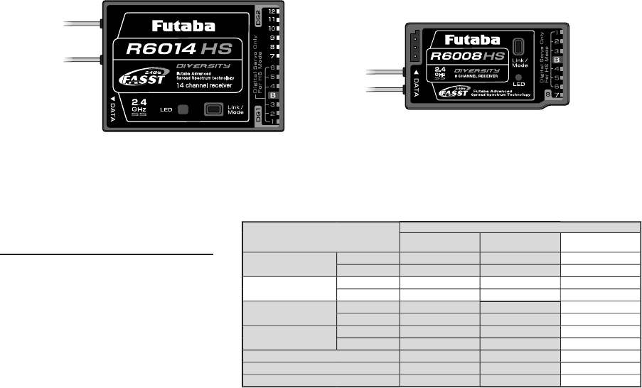
RE
C
EIVER: R6014H
S/
R6008H
S
• T
h
ese mo
d
e
l
s
h
ave two
(
2
)
operat
i
on mo
d
e as s
h
own
b
e
l
ow.
N
ormal mode
/
H
ig
h
S
peed mode
Th
e "Norma
l
mo
d
e" accepts an
y
t
y
pe of servos or t
h
e per
i
p
h
era
l
s as t
h
e frame rate of t
h
e output
i
s 14ms. T
h
e "H
igh
S
pee
d
mo
d
e" on
l
y accept t
h
e
di
g
i
ta
l
servos for outputs from 1c
h
to 6c
h
,
i
nc
l
u
di
ng BLS ser
i
es, an
d
most per
i
p
h
era
l
equ
i
pments suc
h
as t
h
e
gy
ros or
b
rus
hl
ess ESCs. T
h
e frame rate of t
h
e outputs
i
s 7ms.
Th
e outputs for ot
h
er c
h
anne
l
s
i
n
di
cate
d
b
e
l
ow a
ll
ow to use an
y
t
y
pe of servos as t
h
e frame rate of t
h
ese outputs are st
ill
1
4ms on t
h
e H
igh
Spee
d
mo
d
e
.
R
6008HS - 7c
h
an
d
8c
h
R
6014H
S
- 7c
h
to 1
2
ch
, DG1, D
G
2
R6014H
S
R
6008H
S
•
Futa
b
a FA
SS
T-
2
.4G R6014HS,R6014FS, R6008HS or R608FS rece
i
ver ma
y
b
e use
d
w
i
t
h
t
h
e 10CG a
t
2.4
G
-10ch m
ode.
Futa
b
a FA
SS
T
-
2
.
4G R607FS, R617FS, R616FFM or R6004FF rece
i
ver ma
y
b
e use
d
w
i
t
h
t
h
e 10CG a
t
2
.4
G
-7ch mode.
FASST transmitter module, system
a
nd receiver compatibilit
y
Tr
a
n
s
mitt
er
Recei
v
e
r
R606F
S
R6004FF
,
R616FFM
,
R
607FS, R617FS
R608F
S,
R6008H
S,
R6014FS, R6014H
S
TM-14 Modul
e
M
ult
i
-ch mode
—
—
O
ka
y
7
c
h
mo
de
O
ka
y
O
ka
y
—
T10CG 2.4G System
10
c
h
mo
d
e
—
—
O
kay
7
ch mod
e
O
ka
y
O
ka
y
—
TM
-1
0
M
o
d
u
le
1
0c
h
mo
d
e
—
—
O
kay
7c
h m
ode
O
kay
O
kay
—
TM
-8
M
o
d
u
l
e8ch mod
e
—
—
O
ka
y
7ch
m
ode
—
O
kay —
TM-7 Module
—
O
ka
y
—
T7
C
2.4
G
Sy
ste
m
O
ka
y
O
ka
y
—
T6EX 2.4G Syste
m
O
kay
O
kay —
S
ER
VOS
3
O
HDVHVHHWHF
K
Q
L
FD
O
VSHF
L¿
FDW
L
RQVSD
J
HIRUVSHF
L¿
FVRQW
K
HVHUYRV
7KHLQFOXGHGUHFHLYHULVFRPSDWLEOHZLWKDOO-SOXJ)XWDEDVHUYRVLQFOXGLQJUHWUDFWZLQFKDQGGLJLWDOVHUYRV

9
CONTENTS AND TECHNICAL SPECIFICATIONS
6SHFL¿FDWLRQVDQGUDWLQJVDUHVXEMHFWWRFKDQJHZLWKRXWQRWLFH
Your 10CAG, 10CHG or 10CG (packaged with an 8 or a 14-channel FASST-2.4G receiver) system includes the
following components:
•
T10CAG, T10CHG or T10CG Transmitter
•
R6008HS or R6014HS Receiver
• N
55%&+*RQO\RU15-&$*RQO\1L&GEDWWHU\
& Charger
• Switch harness
• Aileron extension cord
• Neck strap
* The set contents depend on the type of set.
Transmitter T10CAG/HG/G
(2-stick, 10-channel, FASST-2.4G system)
Transmitting frequency: 2.4GHz band
Modulation: 2.4G-7ch or 2.4G-10ch, switchable
Power supply: 9.6V NT8S700B Ni-Cd battery
Receiver R6008HS/R6014HS
(Dual antenna diversity)
Power requirement: 4.8V or 6.0V battery or regulated
output from ESC, etc. (*1)
6L]H5+6[ [LQ [[PP
R6014HS: 2.06 x 1.48 x 0.63 in. (52.3 x 37.5 x 16.0 mm)
:HLJKW5+6R]J5+6R]J
(*1) Be sure that when using ESC's regulated output the
capacity of the ESC must meet your usage condition.
Usage condition on "High Speed mode"
(R6008HS/R6014HS)
CAUTION
Outputs from 1ch to 6ch accept the digital
servos only or most type of peripherals.
If any analog servos connected to these output as it
will cause malfunction. Please check the peripherals
if there's any malfunction with whole stick lever
throw. If any malfunction occur please change the
operation mode to "Normal mode."
Output of other channels shown below allow to use
any type of servos.
R6008HS - 7ch and 8ch
R6014HS - 7ch to 12ch, DG1, DG2
(For Operation Mode Selection, see p.20)
(Suggested Servo for use with your 10CG system)
Servo S9252 (Digital servo)
Control system: Pulse width control, 1.52 ms neutral
Power requirement: 4.8 V (from receiver)
Output torque: 91.7 oz.-in. (6.6 kg-cm) at 4.8V
2SHUDWLQJVSHHGVHFDW9
Size: 1.57 x 0.79 x 1.44 in. (40 x 20 x 36.6 mm)
Weight: 1.76 oz. (50 g)
Servo S9255 (Digital servo)
Control system: Pulse width control, 1.52 ms neutral
Power requirement: 4.8 V (from receiver)
Output torque: 125.0 oz.-in. (9.0 kg-cm) at 4.8V
2SHUDWLQJVSHHGVHFDW9
Size: 1.57 x 0.79 x 1.44 in. (40 x 20 x 36.6 mm)
Weight: 1.94 oz. (55 g)
Servo S3151 (Standard, Digital servo)
Control system: Pulse width control, 1.52 ms neutral
Power requirement: 4.8 V (from receiver)
Output torque: 43.1 oz.-in. (3.1 kg-cm) at 4.8V
2SHUDWLQJVSHHGVHFDW9
Size: 1.59 x 0.79 x 1.42 in. (40.5 x 20 x 36.1 mm)
Weight: 1.48 oz. (42 g)
Servo S3001 (Standard, ball-bearing)
Control system: Pulse width control, 1.52 ms neutral
Power requirement: 4.8 - 6.0V (from receiver)
Output torque: 41.7 oz.-in. (3.0 kg-cm)
2SHUDWLQJVSHHGVHF
Size: 1.59 x 0.78 x 1.41 in. (40.4 x 19.8 x 36 mm)
Weight: 1.59 oz. (45.1g)
10
The following additional accessories are available from your dealer. Refer to a Futaba catalog for more information:
•CAMPac 0HPRU\ PRGXOH WKH RSWLRQDO '3... CAMPac increases your model storage capability (to
PRGHOVIURPDQGDOORZV\RXWRWUDQVIHUSURJUDPVWRDQRWKHU&*&WUDQVPLWWHU1RWHWKDWGDWDFDQQRWEH
WUDQVIHUUHGWRIURPDQ\RWKHUPRGHORIWUDQVPLWWHULH8=HWF
However, CAMPacZKLFKVDYHGWKHGDWDRI7&7&6WUDQVPLWWHULVFRQYHUWLEOHIRUWKHGDWDRIWKLV&*&
transmitter. See p.17 for the conversion method.
Insertion of a CAMPac containing data of a different transmitter type (ex: 9Z) will result in a complete
CAMPac data reset and loss of all data.
• NT8S Transmitter battery pack - the (700mAh) transmitter Ni-Cd battery pack may be easily exchanged with a fresh one
WRSURYLGHHQRXJKFDSDFLW\IRUH[WHQGHGÀ\LQJVHVVLRQV
7UDLQHUFRUGWKHRSWLRQDOWUDLQHUFRUGPD\EHXVHGWRKHOSDEHJLQQLQJSLORWOHDUQWRÀ\HDVLO\E\SODFLQJWKHLQVWUXFWRU
on a separate transmitter. Note that the 10CG transmitter may be connected to another 10CG system, as well as to many
other models of Futaba transmitters. The 10CG transmitter uses the newer rectangular type cord plug. Both new-to-new
and new-to-round plug style trainer cords are available.
1HFNVWUDSDQHFNVWUDSPD\EHFRQQHFWHGWR\RXU7&*V\VWHPWRPDNHLWHDVLHUWRKDQGOHDQGLPSURYH\RXUÀ\LQJ
precision, since your hands won’t need to support the transmitter’s weight.
• Y-harnesses, servo extensions, etc - Genuine Futaba extensions and Y-harnesses, including a heavy-duty version with
heavier wire, are available to aid in your larger model and other installations.
FHOO9UHFHLYHUEDWWHU\SDFNV$OO)XWDEDDLUERUQHHTXLSPHQWH[FHSWWKDWZKLFKLVVSHFL¿FDOO\ODEHOHGRWKHUZLVH
is designed to work with 4.8V (Ni-Cd 4 cells) or 6.0V (Ni-Cd 5 cells or alkaline 4 cells). Using a 6.0V pack increases the
FXUUHQWÀRZWRWKHVHUYRVZKLFKDFFHOHUDWHVWKHLUUDWHRIUHVSRQVHDQGWKHLUWRUTXH+RZHYHUEHFDXVHRIWKLVIDVWHUFXUUHQW
GUDZDFHOOEDWWHU\SDFNRIWKHVDPHP$KUDWLQJZLOOODVWDSSUR[LPDWHO\WKHWLPHRIDFHOOSDFN
• Gyros - a variety of genuine Futaba gyros are available for your aircraft or helicopter needs. See p.73 for aircraft or p.
107 for helicopter gyro information.
• Governor (GV1) - for helicopter use. Automatically adjusts throttle servo position to maintain a constant head speed
regardless of blade pitch, load, weather, etc. See p. 108 for details.
• Receivers - various models of receivers may be purchased for use in other models. (See p. 8.)
11
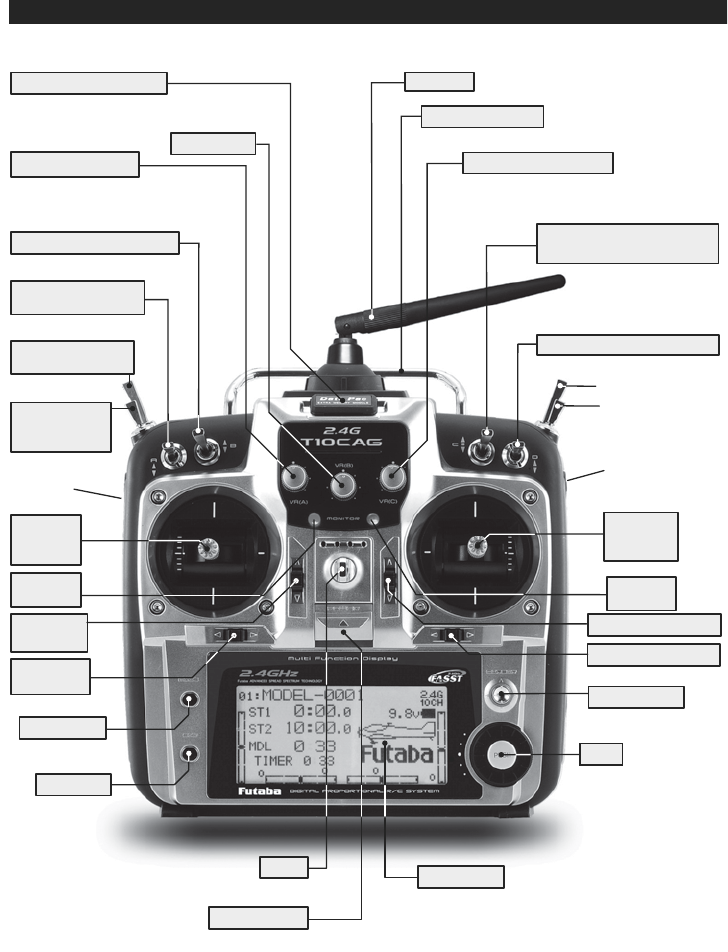
7KLV¿JXUHVKRZVWKHGHIDXOWVZLWFKDVVLJQPHQWVIRUD&$*0RGHV\VWHPDVVXSSOLHGE\WKHIDFWRU\
You can change many of the switch positions or functions by selecting a new position within
the setting menu for the function you wish to move. (Example: move aileron dual rates to switch C
to create triple rates. See p. 42 for details.)
* Power LED blinks to indicate if any mix switches are activated.
** RF LED is blue when the transmission link is solid and the radio is transmitting properly.
CAMPac or Dust Cap
TRANSMITTER CONTROLS - AIRPLANE
SW(B)
VR(A)
VR(B)
SW(A)
SW(F)
SW(E)
VR(D)
VR(E)
VR(C)
SW(G)
SW(H)
SW(D)
SW(C)
CH8 Knob
This controls CH6, and if flaperon mixing
is activated controls the flap.
Flap Trim Control
Rudder Dual Rate Switch / CH9
Elevator Dual Rate
Snap Roll or
Trainer Switch
Landing Gear
Switch
/CH5
Rudder
/Throttle
Stick
Power
LED*
Throttle
Trim Lever
Rudder
Trim Lever
LCD Panel
Power Switch
(Up position: ON)
Hook
(for optional neckstrap)
MODE Key
END Key
Cursor Lever
Aileron Trim Lever
Dial
Elevator Trim Lever
Elevator
/Aileron
Stick
Aileron Dual Rate Switch
Elevator - Flap Mixing or
Airbrake Mixing Switch
Spoiler/CH7 Control
This knob is disabled if aileron differential
is activated.
Carrying Handle
Antenna
LED**
RF
Switch / CH10
12
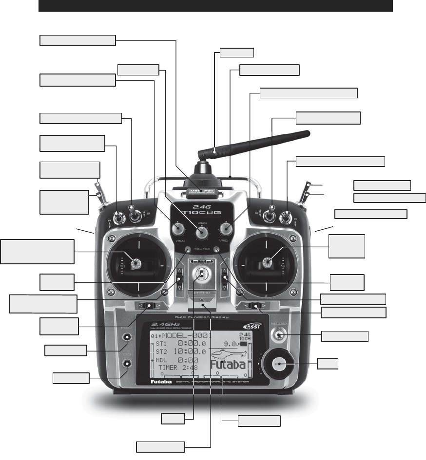
7KLV¿JXUHVKRZVWKHGHIDXOWVZLWFKDVVLJQPHQWVIRUD&+*0RGHV\VWHPDVVXSSOLHGE\WKHIDFWRU\
You can change many of the switch positions or functions by selecting a new position within
the setting menu for the function you wish to move. (Example: move aileron dual rates to switch C
to create triple rates. See p. 42 for details.)
* Power LED blinks to indicate if any mix switches are activated.
** RF LED is blue when the transmission link is solid and the radio is transmitting properly.
CAMPac or Dust Cap
TRANSMITTER CONTROLS - HELI
SW(B)
VR(A)
VR(B)
SW(A)
SW(F)
SW(E)
VR(D) VR(E)
VR(C)
SW(G)
SW(H)
SW(D)
SW(C)
CH8 Knob
Hovering - Pitch Knob
Rudder Dual Rate Switch/CH9
Elevator Dual Rate
Switch/CH10
Idle-up 3 Switch
Idle-up 1&2
Switch
Throttle/Collective
Pitch & Rudder Stick
Throttle/Collective
Trim Lever
Power
LED*
Rudder
Trim Lever
LCD Panel
Power Switch
(Up position: ON)
Hook
(for optional neckstrap)
Aileron Trim Lever
Dial
Elevator Trim Lever
Elevator
/Aileron
Stick
Aileron Dual Rate Switch
Throttle - Hold Switch
Trainer Switch
Governor Switch
Hovering - Throttle Knob/CH7
Carrying Handle
LED**
RF
Antenna
MODE Key
END Key
Cursor Lever
High-pitch Lever
13
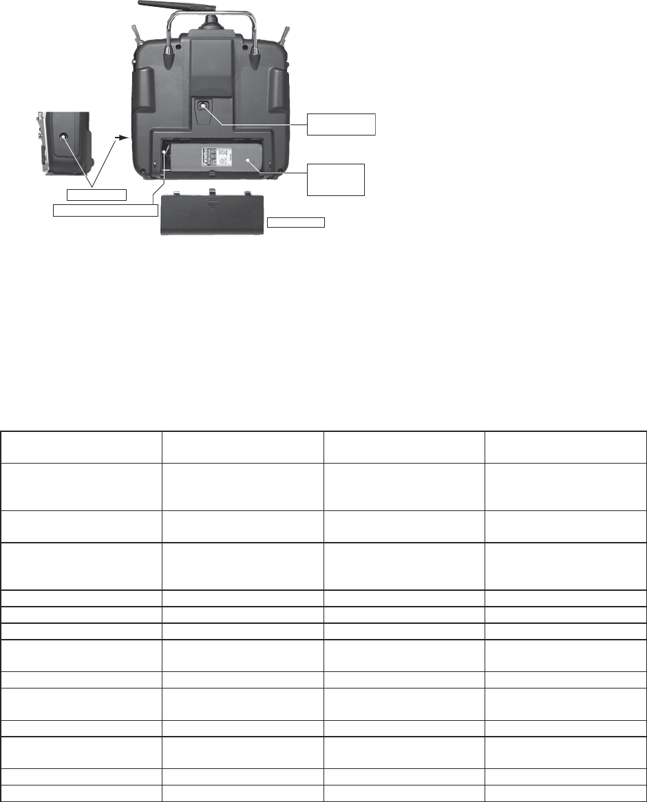
NOTE: If you need to remove or replace
the transmitter battery, do not pull on its
wires to remove it. Instead, gently pull on the
FRQQHFWRUV SODVWLF KRXVLQJ ZKHUH LW SOXJV LQWR
the transmitter.
Battery connector location
Charging jack
Trainer function
connector
Battery cover
NT8S
Ni-Cd battery
pack
SWITCH ASSIGNMENT TABLE
• The factory default functions activated by the switches and knobs for a 10CAG Mode 2 transmitter are shown below.
• Most 10CG functions may be reassigned to non-default positions quickly and easily.
• Basic control assignments of channels 5-10 are quickly adjustable in AUX-CH (see p. 46). For example, the channel 5
servo, which defaults to SWITCH E for retract use, can easily be unassigned (NULL) to allow for easy use as a second
rudder servo in a mix, or to a slider or dial for bomb door or other control.
• Note that most functions need to be activated in the programming to operate.
• 10CAG Mode 1, 10CHG, and 10CG transmitter functions are similar but reverse certain switch commands. Always
check that you have the desired switch assignment for each function during set up.
Switch/Knob
A or H
Airplane (ACRO) Sailplane/Glider (GLID) Helicopter (HELI)
SWITCH A elevator dual rate
ch10
elevator dual rate
GRZQ EXWWHUÀ\RQ
ch10
elevator dual rate
ch10
SWITCH B rudder dual rate
ch9
rudder dual rate
ch9
rudder dual rate
ch9
SWITCH C up = ELE-FLP on
FHQWHUGRZQ IDLE-DOWN
down = AIRBRAKE on
up = ELE-FLP on
center = Distance cond.
down = Landing cond.
governor
SWITCH D aileron dual rate aileron dual rate aileron dual rate
SWITCH E or G* ODQGLQJJHDUFK WKURWWOHKROGFK
SWITCH F or H* VQDSUROOWUDLQHU trainer WUDLQHUTHR-CUT
SWITCH G or E* none up = Speed cond.
down = Start cond.
idle-up 1 and 2
SWITCH H or F* none LGOHXSJ\UR
KNOB A ÀDSFK
ÀDSWULPLIFLAPERON on)
ÀDS
ch6
HOVERING PITCH
KNOB B ch 8 ch 8 ch 8
KNOB C VSRLOHUFK
(disabled if AIL-DIFF on)
ch 7
(disabled if AIL-DIF on)
HOVERING THROTTLE
ch7
SLIDER D none ch 5 none
SLIDER E none none HI-PIT
*On the 10CAG Mode 2 transmitters, the TOP LEFT SWITCHES are spring-loaded and 2-position; on the 10CAG Mode 1, 10CHG, and 10CG,
those switches are on the right side. For consistency, the switch position’s designation remains the same (upper left is F, etc), but the functions are
moved to match the switch type.
14
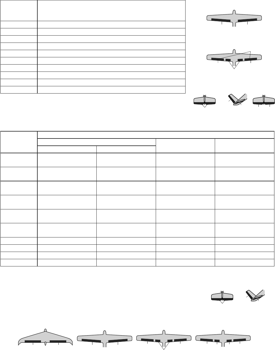
RECEIVER AND SERVO CONNECTIONS
Receiver
Output and
Channel
Aircraft (ACRO)
1DLOHURQVDLOHURQ1FRPELQHGÀDSDLOHURQ2
2 elevator
3 throttle
4 rudder
5VSDUHODQGLQJJHDUDLOHURQ1,3FRPELQHGÀDSDQGDLOHURQ2,3
6VSDUHÀDSVFRPELQHGÀDSDQGDLOHURQ2
7VSDUHDLOHURQ1
8VSDUHHOHYDWRU4PL[WXUHFRQWURO
9 spare
10 spare
1Aileron Differential mode (AILE-DIFF). (See p. 54).
2Flaperon mode. (See p. 52).
3Using Second Aileron option, second aileron servo output is sent to channels 5 and 6. ( AILE-2) (See
p. 55)
4AILEVATOR (dual elevator) mode. (See p. 57).
Receiver
Output and
Channel
Sailplane/Glider (GLID)
GLID (1A+1F) GLID (2A+1F)
(AILE-DIFF)
GLID (2A+2F)
(AILE-DIFF)
ELEVON FLAPERON
1 combined elevator-2 &
aileron-1
combined flap-2 &
aileron-1
aileron-1 aileron-1
2 combined elevator-1 &
aileron-2
HOHYDWRUFRPELQHG
rudder-2 & elevator-12
HOHYDWRUFRPELQHG
rudder-2 & elevator-12
HOHYDWRUFRPELQHG
rudder-2 & elevator-12
3VSDUHPRWRU VSDUHPRWRUFRPELQHG
ÀDSDLOHURQ3
VSDUHPRWRU VSDUHPRWRUVSRLOHU1
4 rudder UXGGHUFRPELQHG
rudder-1 & elevator-22
UXGGHUFRPELQHG
rudder-1 & elevator-22
UXGGHUFRPELQHG
rudder-1 & elevator-22
5VSDUHVSRLOHU1VSDUHVSRLOHU1FRPELQHG
ÀDSDLOHURQ3
VSDUHVSRLOHU1ÀDS
6ÀDSV combined flap-1 &
aileron-2
ÀDSV ÀDS
7 spare spare aileron-2 aileron-2
8VSDUHVSRLOHUVVSRLOHU1VSDUHVSRLOHUVVSRLOHU1VSDUHVSRLOHUVVSRLOHU1VSDUHVSRLOHUVVSRLOHU1
9 spare spare spare spare
10 spare spare spare spare
12-servo spoiler mode (SPOILER). (See p. 83).
2V-tail mixing mode. (See p. 58).
3Using Second Aileron option, second aileron servo output is sent to channels 5 and 6
and channels 3 and 6. ( AILE-2) (See p. 55)
ACRO
(FLAPERON)
AIL12
FLP22
(CH1)
AIL22
FLP12
(CH6)
AIL
(CH1)
AIL11
(CH1)
FLP
(CH6)
ACRO
(w/FLAP)
AIL21
(CH7)
(Wing Type)
(V-TAIL)
ELE1
RUD2
(CH2)
ELE2
RUD1
(CH4)
(NORMAL)
ELE
(CH2)
(AILVATOR)
ELE1
AIL3
(CH2)
ELE2
AIL4
(CH8)
(Tail Type)
AIL1
ELE2
(CH1)
GLID(1A+1F)
(ELEVON)
AIL2
ELE1
(CH2)
GLID(1A+1F)
(FLAPERON)
AIL1
FLP2
(CH1)
AIL2
FLP1
(CH6)
AIL1
(CH1)
FLP1
(CH6)
FLP2
(CH5)
AIL2
(CH7)
GLID(2A+2F)
AIL1
(CH1)
AIL2
(CH7) FLP
(CH6)
GLID(2A+1F)
(Wing Type)
(V-TAIL)
ELE1
RUD2
(
CH2
)
ELE2
RUD1
(CH4)
(NORMAL)
ELE
(CH2)
(Tail Type)
15
The initial charge, and any charge after a complete discharge, should
be at least 18 hours to ensure full charge. The batteries should be left
RQFKDUJH IRUDERXWKRXUVZKHQUHFKDUJLQJ WKHVWDQGDUG15-
NR4F1500 and NT8S700B Ni-Cd batteries.
We recommend charging the batteries with the charger supplied
with your system. Note that the use of a fast charger may damage the
batteries by overheating and dramatically reduce their lifetime.
You should fully discharge your system’s Ni-Cd batteries periodically to prevent a condition called memory.
)RUH[DPSOHLI\RXRQO\PDNHWZRÀLJKWVHDFKVHVVLRQRU\RXUHJXODUO\XVHRQO\DVPDOODPRXQWRIWKHEDWWHULHV
capacity, the memory effect can reduce the actual capacity even if the battery is fully charged. You can cycle your
batteries with a commercial cycling unit*, or by leaving the system on and exercising the servos by moving the
transmitter sticks until the transmitter shuts itself off. Cycling should be done every four to eight weeks, even
during the winter or periods of long storage. Keep track of the batteries capacity during cycling; if there is a
noticeable change, you may need to replace the batteries.
*Note that the 10CG transmitter system has electronic protection from overcharging and reverse polarity via a poli-switch. It does NOT have a
GLRGHLQWKHFKDUJHFLUFXLWDQGPD\EHGLVFKDUJHGSHDNFKDUJHGZLWKWKHEDWWHU\LQWKHWUDQVPLWWHU
DO NOT attempt to charge your 8-cell transmitter pack on the 4-cell receiver plug of the wall charger!
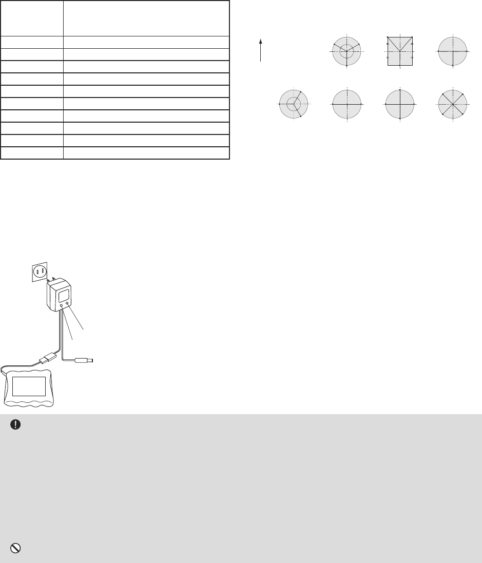
CHARGING THE Ni-Cd BATTERIES
Charging Your System’s Batteries
1. Connect the transmitter charging jack and airborne Ni-Cd batteries to the transmitter and receiver connectors of the
charger.
2. Plug the charger into a wall socket.
3. Check that the charger LED lights.
Receiver
Output and
Channel
Helicopter (HELI)
1 aileron (cyclic roll)
2 elevator (cyclic pitch)
3 throttle
4 rudder
5VSDUHJ\UR
6 pitch (collective pitch)
7VSDUHJRYHUQRU
8VSDUHPL[WXUHFRQWURO
9 spare
10 spare
(Swash Type)
HR3H-1 H-3
ELE ELE
ELE1
ELE2
120˚
120˚120˚
PIT
(AIL)
AIL
(PIT)
PIT
(AIL)
AIL
(PIT)
HN3
120˚
120˚
120˚
ELE
PIT
AIL
HE3
ELE
PIT
(AIL)
AIL
(PIT)
PIT
(AIL)
AIL
(PIT)
H-2
PIT
FRONT
AIL
H-4
ELE1
ELE2 AIL
PIT
H4X
(Normal linkage type)
H-1:each servo linked
to the swashplate
independently.
Charger
TX: Transmitter charging indicato
r
RX: Receiver charging indicator
To transmitter charging jack
Receiver Ni-Cd battery
16
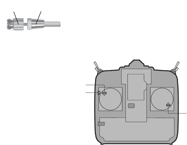
Adjusting the length of the non-slip control sticks
<RXPD\DGMXVWWKHWHQVLRQRI\RXUVWLFNVWRSURYLGHWKHIHHOWKDW\RXSUHIHUIRUÀ\LQJ7RDGMXVW\RXUVSULQJV\RX¶OOKDYH
to remove the rear case of the transmitter. First, remove the battery cover on the rear of the transmitter. Next, unplug the
battery wire, and remove the battery from the transmitter. Next, using a screwdriver, remove the four screws that hold the
transmitter’s rear cover in position, and put them in a safe place. Gently ease off the transmitter’s rear cover. Now you’ll
VHHWKHYLHZVKRZQLQWKH¿JXUHDERYH
Using a small Phillips screwdriver, rotate the adjusting screw for each stick for the desired spring tension. The tension
increases when the adjusting screw is turned clockwise.
:KHQ\RXDUHVDWLV¿HGZLWKWKHVSULQJWHQVLRQVUHDWWDFKWKHWUDQVPLWWHUVUHDUFRYHU:KHQWKHFRYHULVSURSHUO\LQSODFH
reinstall and tighten the four screws. Reinstall the battery and cover.
Adjusting Display Contrast:
To adjust the display contrast, from the home menu press and hold the END BUTTON.
Turn the DIAL while still holding the END BUTTON:
clockwise to brighten
counterclockwise to darken the display
Let go off the DIALand the BUTTON.
You may change the length of the control sticks to make your transmitter more
comfortable to hold and operate. To lengthen or shorten your transmitter’s
VWLFNV¿UVWXQORFNWKHVWLFNWLSE\KROGLQJORFNLQJSLHFH%DQGWXUQLQJVWLFNWLS
A counterclockwise. Next, move the locking piece B up or down (to lengthen
or shorten). When the length feels comfortable, lock the position by turning
locking piece B counterclockwise.
Stick tip A Locking piece B
Stick lever tension adjustment
Mode 2 transmitter with rear cover removed.
Aileron
Elevator
Rudde
r
Stick Stick
17
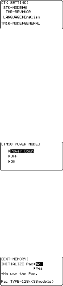
Changing Modes (TX SETTING):
Hold down MODE and END keys while turning on the transmitter to call TX SETTING menu.
Stick Mode: The screen reads "STK-MODE". Change this to the correct mode. Note that this will
NOT change the throttle and elevator rachets, etc. Those are mechanical changes that must be
done by a service center.
Throttle Reverse:THR-REV is a special function that reverses the entire throttle control, including moving the trim
functionality to the Stick’s upper half. To use THR-REV,CURSOR DOWN to THR-REV and turn the DIAL to REV. Turn the
transmitter off and back on. This change affects all models in the radio. (GLID only): The separate THR-REV settings for each
model can be set. (See p.33)
Display language: can be selected the display language of the function name, etc. in each function menu. The screen reads
"LANGUAGE". Change this to the desired language.
Area Selection (Frequency Range):
The T10CG transmitter has been designed to function in many countries. If you will be utilizing this transmitter in a
country other than France, please make sure that TM10-MODE is set to "GENERAL". If, however, this module will be utilized
in France, it must be set to "FRANCE".
Power Down mode (TM10 POWER MODE):
We have installed a special "Power Down Mode" for doing a ground range check. Hold down
DIAL while turning on the transmitter to call TM10 POWER MODE menu.
Power Down Mode: To activate the "Power Down Mode" press DIAL and the home screen will appear. During this mode,
the RF power is reduced so the range test can be performed. In addition, when this mode is activated the blue LED on the
front of the transmitter starts blinking and the transmitter gives users a warning with a beep sound every 3 seconds.
The "Power Down Mode" continues for 90 seconds and after that the power will go back to the normal level. To exit the
"Power Down Mode" before the 90 seconds, press DIAL again. This mode is available 1 time only so if you need to re-use
this function the transmitter power must be cycled. NEVERVWDUWÀ\LQJZKHQWKH3RZHU'RZQ0RGHLVDFWLYH
Power Off Mode: To use the RF power off mode, CURSOR DOWN to OFF and press DIAL. During this mode, the RF
power is turned off. The blue LED on the front of the transmitter is turn off.
CAMPac Initializing Method and Data Conversion (T9C/T9CS to T10CG):
Insertion of a new CAMPac or a CAMPac containing data of a different transmitter type will
open EXT-MEMORY menu after turning the transmitter on.
To initialize the CAMPac, CURSOR DOWN to "Yes" and press DIAL and the check display of "OK?" will appear. Press
DIAL again, the initializing of the CAMPac will start.
7RFRQYHUWWKH&$03DFGDWDIURP7&7&6WR7&*VHOHFWWR1RE\CURSOR lever and then press DIAL and the
home screen will appear. See p.30 for the conversion method.
18
RADIO INSTALLATION
Follow these guidelines to properly mount the servos, receiver and battery.
• Make certain the alignment tab on the battery, switch and servo connectors is oriented correctly and “keys” into the
corresponding notch in the receiver or connectors before plugging them in. When unplugging connectors, never pull on
the wires. Always pull on the plastic connector instead.
• If your aileron servo (or others) are too far away to plug into the receiver, use an aileron extension cord to extend the
length of the servo lead. Additional Futaba extension cords of varying lengths are available from your hobby dealer.
Always use an extension of the proper length. Avoid plugging multiple extensions together to attain your desired length.
If distance is greater than 18” or multiple or high current draw servos are being used, use Futaba Heavy-Duty servo
extensions.
5HFHLYHU9LEUDWLRQDQG:DWHUSURR¿QJ7KHUHFHLYHUFRQWDLQVSUHFLVLRQHOHFWURQLFSDUWV%HVXUHWRDYRLGYLEUDWLRQVKRFN
and temperature extremes. For protection, wrap the receiver in foam rubber or other vibration-absorbing materials.
It is also a good idea to waterproof the receiver by placing it in a plastic bag and securing the open end of the bag with
a rubber band before wrapping it with foam rubber. If you accidentally get moisture or fuel inside the receiver, you may
experience intermittent operation or a crash. If in doubt, send the receiver for service.
Servo Rubber
grommet Servo Rubber
grommet
• Always mount the servos with the supplied rubber grommets. Do not over
tighten the screws. No part of the servo casing should contact the mounting
UDLOVVHUYRWUD\RUDQ\RWKHUSDUWRIWKHDLUSODQHKHOLFRSWHUVWUXFWXUH2WKHUZLVH
YLEUDWLRQZLOOEHWUDQVPLWWHGWRWKHVHUYRFDXVLQJSUHPDWXUHZHDUDQGRUVHUYR
failure.
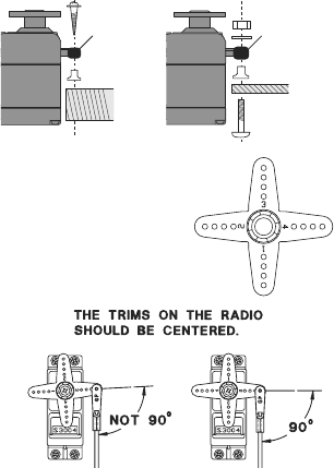
• Note the small numbers (1, 2, 3, 4) molded into each arm on the Futaba 4-arm servo arms. The numbers
indicate how many degrees each arm is “off” from 90 degrees to correct for minute manufacturing
deviations from servo to servo.
• To center the servos, connect them to the receiver and turn on the transmitter
and receiver. Center the trims on the transmitter, then find the arm that will be
perpendicular to the pushrod when placed on the servo.
• After the servos are installed, operate each servo over its full travel and check that the pushrods and servo arms do not
bind or contact each other. Also make sure the controls do not require excess force to operate. If there is an objectionable
buzzing sound coming from a servo, there is probably too much resistance in the control. Find and correct the problem.
Even if there is no servo damage, excess battery drain will result.
• Use the mounting plateIURPWKHUHFHLYHURQRIIVZLWFKDVDWHPSODWHIRUWKHFXWRXWDQGVFUHZKROHV0RXQWWKHVZLWFK
on the side of the fuselage opposite the engine exhaust, and where it won’t be inadvertently turned on or off during
handling or storage. Be certain the switch moves without restriction and “snaps” from ON to OFF, and that the cutout
allows full motion of the switch in both directions.
• When you install the switch harness to the helicopter, please use the switch cover. Generally sandwich the frame by
switch and switch cover and securely tighten the screws. Different models might require different installations. In that
case, please follow the model instruction manual.
19
Fasten about 5-10cm
from the servo outlet
so that the lead wire
is neat.
Margin in the lead wire.
• To prevent the servo lead wires from being broken by vibration during
ÀLJKWSURYLGHDPDUJLQVRWKDWWKHZLUHVWLFNVRXWVOLJKWO\DQGIDVWHQLW
at suitable points. In addition, periodically check the wire during daily
maintenance.
IMPORTANT: Since the 2.4GHz have different characteristics than that of the conventional 27MHz and 72MHz
IUHTXHQFLHVSOHDVHUHDGWKLVVHFWLRQFDUHIXOO\WRHQMR\VDIHÀLJKWZLWKWKH*+]V\VWHP
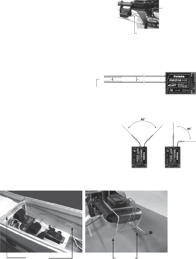
5HFHLYHUV$QWHQQD,QVWDOODWLRQ
Antenna
*Must be kept as straight as possible.
Coaxial cable
R6014HS Receiver
7KH5+65+6KDVWZRDQWHQQDV7KHVHDQWHQQDVKDYH
a diversity function to decrease the chance of a receiving error.
• Since the wavelength of the 2.4GHz is much shorter than that
of the conventional frequencies 27MHz and 72MHz, it is very
susceptible to loss of signal which results in a receiving error.
,Q RUGHUWRDYRLGWKLVSKHQRPHQRQWKH5+65)6
adopted a diversity antenna system.
• To obtain the best results of the diversity function, please refer to the following instructions;
1. The two antennas must be kept as straight as possible. Otherwise it will reduce
the effective range.
2. The two antennas should be placed at 90 degrees to each other.
7KLVLVQRWDFULWLFDO¿JXUHEXWWKHPRVWLPSRUWDQWWKLQJLVWRNHHSWKHDQWHQQDV
away from each other as much as possible.
Larger models can have large metal objects that can attenuate the RF signal.In
this case the antennas should be placed at both sides of the model. Then the best
5)VLJQDOFRQGLWLRQLVREWDLQHGDWDQ\À\LQJDWWLWXGH
3. The antennas must be kept away from conductive materials, such as metal,
carbon and fuel tank by at least a half inch. The coaxial part of the antennas does not need to follow these guidelines, but
do not bend it in a small radius.
4. Keep the antennas away from the motor, ESC, and other noise sources as much as possible.
Antenna Antenna
*The two antennas should be placed at 90 degrees to each other.
*The main purpose of the photo demonstrates how the antenna should be placed.
)RUDFWXDOLQVWDOODWLRQWKHUHFHLYHUPXVWEHZUDSSHGZLWKDVSRQJHRUSODFHGZLWKÀRDWLQJPDWHULDOWR
protect it from vibration.
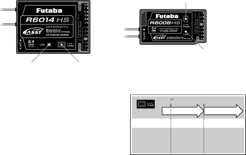
2
0
O
p
erat
i
on Mode
S
elect
(
R6008H
S/
R6014H
S)
:
R6014H
S
R6008H
S
LED
Link
/
Mod
e
S
witc
h
LED
Link
/
Mod
e
S
witc
h
Th
e operat
i
on mo
d
e
i
s on "Norma
l
mo
d
e" from factor
y
s
hi
pp
i
n
g
. W
h
en to c
h
an
g
e t
h
e mo
d
e, p
l
ease fo
ll
ow t
h
e steps s
h
own
below
.
0 to 1 sec. More than 1 sec.
0 sec. 1 sec.
Press and Hold time
Turn on the receiver.
No function
Showing the CURRENT
mode with blink.
Red Blink = Normal
Green/Red Blink =
High Speed
Solid as the mode changed.
Red Solid = Normal
Green/Red Solid = High
Speed
(Become Red after one (1)
second)
㧔Function㧕To change the mode between
Normal and High Speed
㧔LED
Status㧕
1.
T
u
rn
o
ff th
e
r
ece
i
ve
r
.
2
.
Pr
ess
an
d
hold
t
he
L
ink
/
Mod
e
sw
i
tc
h
an
d
turn on t
h
e rece
i
ver.
K
eep the switch hold more than one(1) second. The LED starts
ÀDVKLQJZLWKWKHFXUUHQWVWDWXV
3.
R
ele
a
se
t
he
swi
t
ch.
4
. Turn off the receiver.
By
d
o
i
n
g
t
hi
s step, t
h
e mo
d
e can sw
i
tc
h
over
b
etween two
(
2
)
mo
d
es.
P
lease check the operation mode by observing the LED when turning on the receiver. If possible there's no FASST
WUDQVP
L
WWHUWXUQH
G
RQDURXQ
G
\
RX
L
QRU
G
HUWRPD
N
H
¿
UPHUF
K
HF
N
When turn on the receiver
,
the LED will be
;
•Red when on "Normal mode
"
•Green and Red (makes Orange) when on "High Speed mode". (After two(
2
) seconds, change to Red.)
I
f t
h
ere are some FASST transm
i
tter turne
d
on aroun
d
t
h
e rece
i
ver, t
h
e LED ma
y
s
h
ow t
h
e a
b
ove status for a
b
r
i
ef momen
t
then changed to the status indication as shown in the "LED indication" table
.
21
7UDQVPLWWHUV$QWHQQD
1. The transmitter antenna is adjustable so please make sure that the antenna is never
SRLQWHGGLUHFWO\DWWKHPRGHOZKHQÀ\LQJDVWKLVFUHDWHVDZHDNVLJQDOIRUWKHUHFHLYHU
2. Keep the antenna perpendicular to the transmitter's face to create a better RF condition
for the receiver. Of course this depends on how you hold the transmitter, but in most
cases, adjusting the transmitter antenna so that it is perpendicular to the face will
give the best results. Please adjust the transmitter antenna to the way you hold the
transmitter.
1(9(5JULSWKHDQWHQQDZKHQÀ\LQJDVWKLVGHJUDGHV5)TXDOLW\
WARNING
After the linking is done, please cycle receiver power and check if the receiver to be linked is really under the
control by the transmitter to be linked.
Do not perform the linking procedure with motor's main wire connected or with engine operating as it may result
in serious injury.
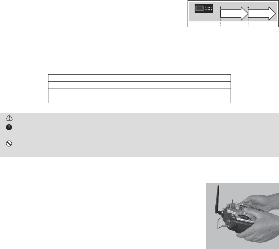
Link Procedure (T10CG transmitter/R6008HS or R6014HS receiver):
Each transmitter has an individually assigned, unique ID code. In order to start operation, the receiver must be linked with
the ID code of the transmitter with which it is being paired. Once the link is made, the ID code is stored in the receiver
and no further linking is necessary unless the receiver is to be used with another transmitter. When you purchase another
5+65+6WKLVSURFHGXUHLVQHFHVVDU\RWKHUZLVHWKHUHFHLYHUZLOOQRWZRUN
0 to 2 sec. More than 2 sec.
0 sec. 2 sec.
Press and Hold time
No function(Function) Re-link(ID set)
1. Place the transmitter and the receiver close to each other within one (1) meter.
2. Turn on the transmitter.
3. Check the LED that is placed on the front side of the transmitter to see if the
RF signal is active. When the blue LED is ON solid, the RF signal is being sent.
4. Turn on the receiver.
5. Press down the Link/Mode switch for more than two seconds, and release the switch. The receiver starts the linking
operation.
:KHQWKHOLQNLQJLVFRPSOHWHWKH/('LQWKHUHFHLYHUZLOOFKDQJHWRVROLGJUHHQ3OHDVHFRQ¿UPWKDWWKHVHUYRVZLOO
now operate by your transmitter. Please refer to the table below for the LED status of the receiver's condition.
LED Indication (R6008HS/R6014HS)
No signal reception Red : On
Receiving signals Green: On
Receiving signals, but ID is unmatched. Green: Blink
Unrecoverable failure (EEPROM, etc.) Red and Green turn on alternately.

22
Range Testing Your R/C System
It is extremely important to range check your models prior to each flying session. This enables you to ensure that
HYHU\WKLQJLVIXQFWLRQLQJDVLWVKRXOGDQGWRREWDLQPD[LPXPHQMR\PHQWIURP\RXUWLPHÀ\LQJ7KH7&*WUDQVPLWWHU
incorporates a system that reduces its power output and allows you to perform such a range check.
Power Down mode (TM10 POWER MODE):
We have installed a special "Power Down Mode" for doing a ground range check. Hold down
DIAL while turning on the transmitter to call TM10 POWER MODE menu.
To activate the "Power Down Mode" press DIAL and the home screen will appear. During
this mode, the RF power is reduced so the range test can be performed. In addition, when this mode is activated the blue
LED on the front of the transmitter starts blinking and the transmitter gives users a warning with a beep sound every 3
seconds.
The "Power Down Mode" continues for 90 seconds and after that the power will go back to the normal level. To exit the
"Power Down Mode" before the 90 seconds, press DIAL again. This mode is available 1 time only so if you need to re-use
WKLVIXQFWLRQWKHWUDQVPLWWHUSRZHUPXVWEHF\FOHG1(9(5VWDUWÀ\LQJZKHQWKH3RZHU'RZQ0RGHLVDFWLYH
1. With the "Power Down Mode" on, walk away from the model while simultaneously operating the controls. Have an
DVVLVWDQWVWDQGE\WKHPRGHOWRFRQ¿UPWKDWDOOFRQWUROVDUHFRPSOHWHO\DQGFRUUHFWO\RSHUDWLRQDO<RXVKRXOGEHDEOHWR
walk approximately 30-50 paces from the model without losing control.
2. If everything operates correctly, return to the model. Set the transmitter in a safe, yet accessible, location so it will be
within reach after starting the engine or motor. Be certain the throttle stick is in the low throttle position, then start the
engine or motor. Perform another range check with your assistant holding the aircraft with the engine running at various
VSHHGV,IWKHVHUYRVMLWWHURUPRYHLQDGYHUWHQWO\WKHUHPD\EHDSUREOHP:HZRXOGVWURQJO\VXJJHVW\RXGRQRWÀ\XQWLO
WKHVRXUFHRIWKHGLI¿FXOW\KDVEHHQGHWHUPLQHG/RRNIRUORRVHVHUYRFRQQHFWLRQVRUELQGLQJSXVKURGV$OVREHFHUWDLQ
that the battery has been fully charged.
2
3
T
RAN
S
MITTER DI
S
PLAY
S
&
BUTTON
S
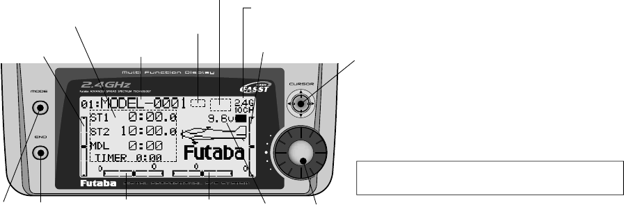
:K
HQ
\
RX
¿
UVWWXUQRQ
\
RXUWUDQVP
L
WWHUDFRQ
¿
UPDW
L
RQ
G
RX
EO
H
E
HHSVRXQ
G
VDQ
G
W
K
HVFUHHQV
K
RZQ
E
H
O
RZDSSHDUV%HIRUH
À\LQJRUHYHQVWDUWLQJWKHHQJLQHEHVXUHWKDWWKHPRGHOW\SHDQGQDPHDSSHDULQJRQWKHGLVSOD\PDWFKHVWKHPRGHOWKDW
\
RXDUHD
E
RXWWR
À\
,I
\
RXDUH
L
QW
K
HZURQ
J
PR
G
H
O
PHPRU
\
VHUYRVPD
\
E
HUHYHUVH
G
DQ
G
WUDYH
O
VDQ
G
WU
L
PVZ
LOO
E
HZURQ
J
l
eading to an immediate crash.
(G
L
WEXWWRQVDQG
6
WDUWXS
6
FUHHQ
DSSHDUVZKHQV
\
VWHP
L
V
¿
UVWWXUQHGRQ
M
O
DE BUTT
O
N
:
(k
e
y)
Press and hold
MO
DE B
U
TT
ON
for one second to open programming menus. Press
N
MODE BUTTON
to switch
N
be
t
wee
nBA
S
I
C
an
d
A
DVAN
C
E
menus.
HELI
on
ly
: Press
MODE BUTTON
to scroll between conditions in certain
N
functions
.
END BUTT
O
N:
(
key
)
Press END BUTTON to return to prev
i
ous screen. C
l
oses funct
i
ons
b
ac
k
to menus, c
l
oses menus to start-up screen.
CU
R
SO
R LE
V
ER
:
C
ontro
l
C
UR
SO
R LEVER WR VFUR
OO
XS
VFUR
OO
G
RZQ
VFUR
OO
O
HIW
VFUR
OO
U
LJK
W DQ
G
VH
O
HFWW
K
HRSW
L
RQ WR H
GL
W Z
L
W
KL
Q D
function.
P
r
ess
C
UR
SO
R LEVERWRSD
J
HXS
SD
J
H
G
RZQZ
L
W
KL
QBA
S
I
C
or
ADVAN
C
Em
e
n
u
o
r a f
u
n
c
t
io
n
.
Tu
rn
DIAL
:
T
u
rn
D
I
A
Lclockwise or counterclockwise to scroll through choices within an option of a function (for example, to
VH
O
HFWZ
KL
F
K
VZ
L
WF
K
FRQWUR
O
V
G
XD
O
WU
L
S
O
HUDWHV
P
res
s
D
IAL
:
Pr
ess
DIAL
to se
l
ect t
h
e actua
l
funct
i
on
y
ou w
i
s
h
to e
di
t from t
h
e menu.
Press DIAL DQGKROGRQHVHFRQGWRFRQ¿UPPDMRUGHFLVLRQVVXFKDVWKHGHFLVLRQWRVHOHFWDGLIIHUHQWPRGHOIURP
m
emor
y
, cop
y
one mo
d
e
l
memor
y
over anot
h
er, tr
i
m reset, store c
h
anne
l
pos
i
t
i
on
i
n Fa
il
Safe, c
h
an
g
e mo
d
e
l
t
y
pe,
reset entire model. System will ask if you are sure.
P
ress
DIAL
a
g
a
i
n to accept c
h
an
g
e.
PUSH
Rudder trim
display
Aileron trim
display
Elevator/Throttle trim
display
2.4G-7CH/10CH:
Modulation indicator
16/64/128: CAMPac display (10CG/10C data)
9C: CAMPac display (9C/9CS data)
Battery
voltage
Timers
Throttle/Elevator trim
display
Model number
and name
Dial
CURSOR lever
END
key
MODE
key
Total timer display <TIMER>
Shows the cumulated ON time. (hours:minutes)
Up/down timer display <ST1.ST2>
(minutes:seconds)
Model timer display <MDL>
Shows the cumulated ON time for each model.(hours:minutes)
MIX: Mixer Alert
Resetting timers:
Select the desired timer with CURSOR lever. The timer
display flashes. To reset the timer, press Dial for one second.
24
WARNING & ERROR DISPLAYS
An alarm or error indication may appear on the display of your transmitter for several reasons, including when the
transmitter power switch is turned on, when the battery voltage is low, and several others. Each display has a unique sound
associated with it, as described below.
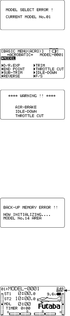
MODEL SELECTION ERROR: Warning sound: 5 beeps (repeated 3 times)
The MODEL SELECTION warning is displayed when the transmitter attempts to load a model memory from a memory
module (optional CAMPac) that is not currently plugged into the transmitter. When this occurs, model No. 01 is
automatically loaded.
'RQRW À\ XQWLO WKH SURSHU PRGHO LVORDGHG LQWR PHPRU\ Reinsert the memory module,
and recall the desired setup using the model select function.
LOW BATTERY ERROR: Warning sound: Continuous beep until transmitter is powered off.
The LOW BATTERY warning is displayed when the transmitter battery voltage drops below 8.5V.
Land your model as soon as possible before loss of control due to a dead battery.
MIXER ALERT WARNING: Warning sound: 5 Beeps (repeated until problem resolved or overridden)
The MIXER ALERT warning is displayed to alert you whenever you turn on the transmitter with
any of the mixing switches active. This warning will disappear when the offending switch or
control is deactivated. Switches for which warnings will be issued at power-up are listed
below:
ACRO:Throttle cut, idle-down, snap roll, airbrake GLID%XWWHUÀ\FRQGLWLRQVHELI:Throttle cut, throttle hold, idle-up
If turning a switch OFF does not stop the mixing warning: When the warning does not stop even when the mixing switch
indicated by the warning display on the screen is turned off, the functions described previously probably use the same
switch and the OFF direction setting is reversed. In short, one of the mixings described above is not in the OFF state. In
this case, reset the warning display by pressing CURSOR LEVER. Then change one of the switch settings of the mixings
duplicated at one switch.
BACKUP ERROR: Warning sound: 4 beeps (repeated continuously)
The BACKUP ERROR warning occurs when the transmitter memory is lost for any reason. If this occurs, all of the data will
be reset when the power is turned on again.
[Note] At this warning display, the transmitter transmits in 2.4G-10CH mode even if the set-up mode is 2.4G-7CH mode.
Do not fly when this message is displayed: all programming has been erased and is not
available. Return your transmitter to Futaba for service.
MEMORY MODULE INITIALIZE DISPLAY
This warning appears when an (optional) CAMPacPHPRU\PRGXOHLVXVHGLQWKHWUDQVPLWWHUIRUWKH¿UVWWLPH:KHQWKH
MODE BUTTON is pressed, initialization of the module begins, after which the memory module can be used. Once the
module is initialized, the display will not appear again.
The 10C CANNOT convert data from other radio types (i.e. 8U, 9Z). Installation of a CAMPac with data from another
radio type will result in reinitialization of the CAMPac and loss of all data.
RF ERROR: Warning sound: A single long beep.
ÀDVKLQJ
The single beep lets you know that the RF output has stopped for any reason. The blue RF
light also goes out. Return your transmitter to Futaba for service.
25
AIRCRAFT (ACRO) MENU FUNCTIONS
Please note that all BASIC menu functions are the same for airplanes (ACRO), sailplanes (GLID), and helicopters (HELI). The
glider BASIC menu includes MOTOR CUT that is discussed in the Glider section and does not include IDLE-DOWN or THR-
CUT; the helicopter BASICPHQXLQFOXGHVDGGLWLRQDOIHDWXUHVVZDVKSODWHDGMXVWPHQWDQGWKURWWOHSLWFKFXUYHVDQGUHYRIRU
1RUPDOÀLJKWPRGHWKDWDUHGLVFXVVHGLQWKH+HOLFRSWHUVHFWLRQ
AIRPLANE (ACRO) FUNCTIONS ................................ 25
Map of Functions........................................................ 26
Quick Guide to Setting up a 4-channel Airplane ...... 27
ACRO BASIC MENU FUNCTIONS ................................ 30
MODEL Submenu: MODEL SELECT,COPY,NAME .......... 30
PARAMETER Submenu: RESET,TYPE,MODUL,ATL,AILE-2,
CONTRAST,BACK-LIGHT,HOME-DISP,USER NAME,LOGIC
SW ............................................................................. 33
Servo REVERSE ........................................................... 38
END POINT .................................................................. 39
Idle Management: IDLE DOWN and THR-CUT .............. 40
'XDO7ULSOH5DWHVDQG([SRQHQWLDOD/R,EXP) .......... 42
TIMER Submenu.......................................................... 45
Auxiliary Channel assignments and CH9 reverse (AUX-
CH) ............................................................................. 46
TRAINER ..................................................................... 47
TRIM and SUB-TRIM ................................................... 48
SERVO Display ........................................................... 49
Fail Safe and Battery FailSafe (F/S) ......................... 50
ACRO ADVANCE MENU FUNCTIONS ........................... 51
Wing types ................................................................ 51
FLAPERON ................................................................... 52
FLAP TRIM .................................................................. 53
Aileron Differential (AILE-DIFF) ................................. 54
Using a 5-channel receiver: AILE-2 ............................ 55
ELEVON (see tail types) ............................................... 56
Tail types ................................................................... 56
ELEVON ....................................................................... 56
Twin Elevator Servos (AILEVATOR) ............................ 57
V-TAIL ......................................................................... 58
SNAP ROLL .................................................................. 59
0L[HVGH¿QLWLRQVDQGW\SHV ..................................... 61
ELEV-FLAP .................................................................... 62
AIRBRAKEBUTTERFLY (crow) ..................................... 63
THROTTLE-NEEDLE ........................................................ 65
THROTTLE DELAY ......................................................... 66
THROTTLE CURVE ........................................................ 67
Linear, Prog. mixes 1-4 ............................................. 68
Curve, Prog. mixes 5-8 ............................................. 71
GYA gyro mixing (GYRO SENSE) ............................... 73
26
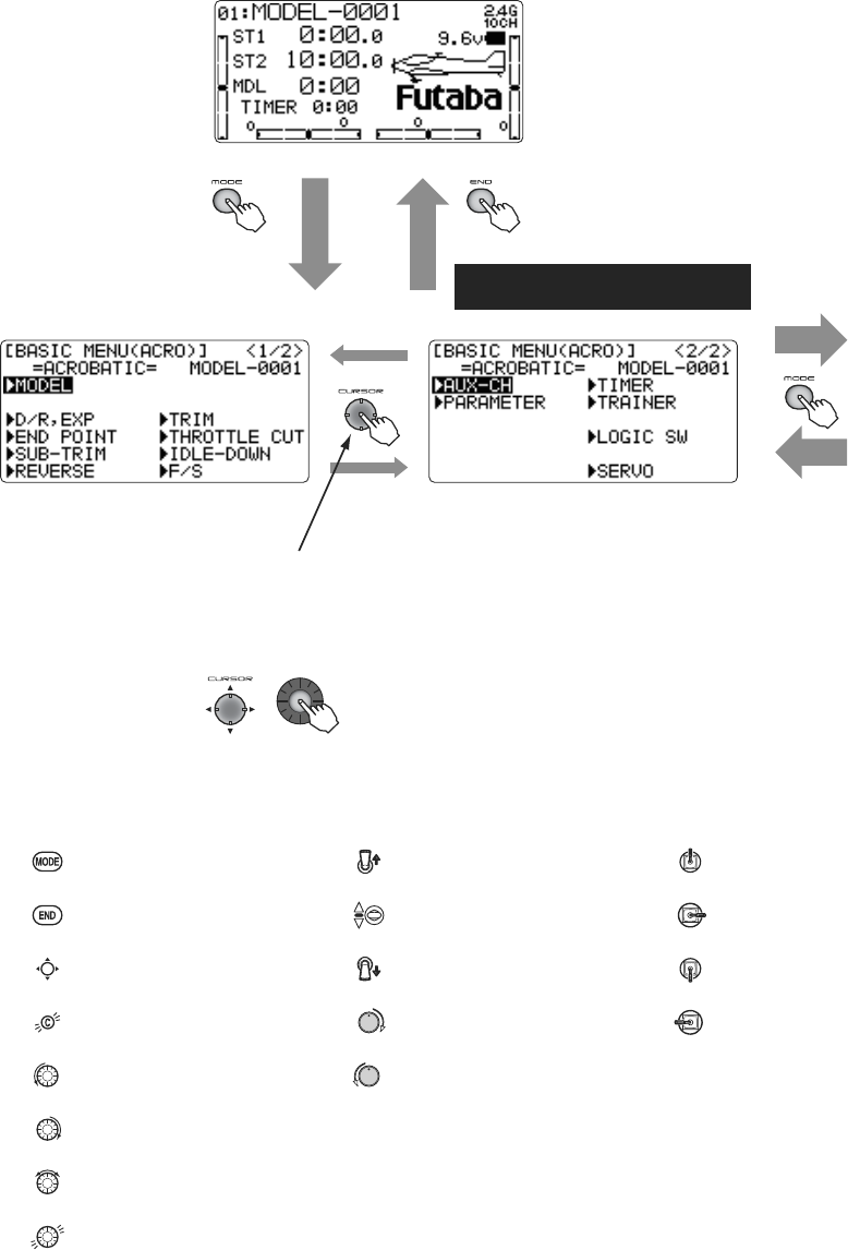
MAP OF ACRO BASIC FUNCTIONS
ACRO Basic Menu
( for one second)
(Startup screen)
(Basic Menu 1/2)
To return to the Startup screen,
press the End key.
(Basic Menu 2/2)
To enter the Basic Menu,
press the Mode key for one second.
Press Mode key to toggle back and forth
between BASIC and ADVANCE menus.
Press Cursor lever to page up and down through the 2 pages of screens
in each menu. Note that all functions which have more than one page have
a <1/2> indicator in the upper right hand corner to indicate page 1 of 2 or
page 2 of 2.
Use Cursor lever to highlight function in Menu screen.
Then press the Dial to choose that function.
Mode Select
End Selection
Cursor Lever
(Down/Up/Left/Right)
Dial Right or Left
Press Dial
Switch Up
Switch at Center
Switch Down
Stick Up
Stick Right
Stick Down
Stick Left
Turn Knob Right
Turn Knob Left
Dial Left
Dial Right
Press Cursor Lever
C
27
A QUICK GUIDE: GETTING STARTED WITH A BASIC 4-CHANNEL AIRCRAFT
This guide is intended to help you get acquainted with the radio, to give you a jump start on using your new radio, and
to give you some ideas and direction in how to do even more than you may have already considered. It follows our basic
format of all programming pages: a big picture overview of what we accomplish; a “by name” description of what we're
doing to help acquaint you with the radio; then a step-by-step instruction to leave out the mystery when setting up your
model.
For additional details on each function, see that function's section in this manual. The page numbers are indicated in the
goals column as a convenience to you.
See p.26 for a legend of symbols used.
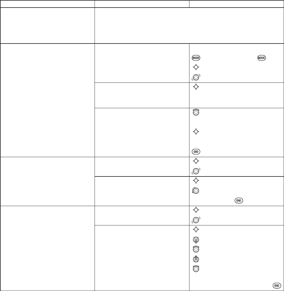
GOALS of EXAMPLE STEPS INPUTS for EXAMPLE
Prepare your aircraft. Install all servos, switches, receivers per your model's instructions. Turn on
transmitter then receiver; adjust all linkages so surfaces are nearly centered.
Mechanically adjust all linkages as close as possible to proper control throws.
Check servo direction. Make notes now of what you will need to change during
programming.
Name the model.
P. 32.
[Note that you do not need to do
anything to "save” or store this data.
Only critical changes such as a MODEL
RESET require additional keystrokes to
accept the change.]
Open the BASIC menu, then open the
MODEL submenu.
Turn on the transmitter.
for 1 second. (If ADVANCE, again.)
C
as needed to highlight MODEL.
to choose MODEL.
Go to MODEL NAME.
C
to NAME.
(First character of model's name is
highlighted.)
Input aircraft's name.
Close the MODEL submenu.
WRFKDQJH¿UVWFKDUDFWHU
When proper character is displayed,
C
to move to next character.
Repeat as needed.
to return to BASIC menu.
Reverse servos as needed for proper
control operation.
P. 38.
In the BASIC menu, open (servo)
REVERSE.
C
to REVERSE.
to choose REVERSE.
Choose desired servo and reverse its
direction of travel. (Ex: reversing rudder
servo.)
C
to CH4: RUDD.
so REV is highlighted.
Repeat as needed.
Adjust Travels as needed to match
model's recommended throws (usually
listed as high rates).
P. 39.
From BASIC menu, choose END POINT.
C
to END POINT.
to choose END POINT.
Adjust the servo's end points.
(Ex: throttle servo)
Close the function.
C
to THROTTLE.
THROTTLE STICK.
until carb barrel closes as desired.
THROTTLE STICK.
until throttle arm just opens carb
fully at full THROTTLE STICK.
Repeat for each channel as needed.
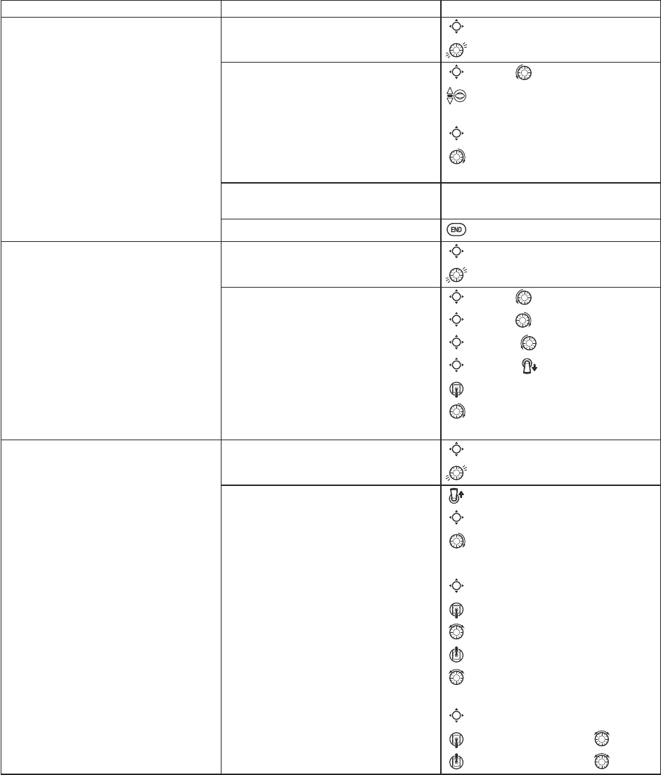
28
With digital trims you don’t shut the engine off with THROTTLE TRIM. Let's set up IDLE-DOWN and "throttle cut" (THR-CUT)
now.
GOALS of EXAMPLE STEPS INPUTS for EXAMPLE
Set up IDLE-DOWN.
P. 40.
IDLE-DOWN slows the engine's idle for
landings, sitting on the runway, and
maneuvers such as spins. The normal
(higher idle) setting (when IDLE-DOWN is
off) is for engine starting, taxi, and most
ÀLJKWPDQHXYHUVWRPLQLPL]HFKDQFHRI
DÀDPHRXW
From the BASIC menu, choose IDLE-
DOWN.
C
to IDLE-DOWN.
to choose IDLE-DOWN.
Activate and adjust IDLE-DOWN.
C
to MIX. to OFF.
C to center position. Screen now
reads ON.
C
to RATE.
to increase rate until engine idles
reliably but low enough to sit still.
Optional: change switch command from
C center-and-down to any other switch.
(Not needed in this example.)
Close the Function.
THR-CUT shuts the engine off completely
ZLWKWKHÀLSRIDVZLWFK
P. 41.
(NOTE: DO NOT assign IDLE-DOWN and
THR-CUT to both positions of a 2position
switch. See IDLE-DOWN for details.)
From the BASIC menu, choose THR-CUT.
C
to THR-CUT.
to choose THR-CUT.
Activate, assign SWITCH and adjust.
Close the function.
C
to MIX. to OFF.
C
to SW. to C.
C
to POSI. to DOWN.
C
to RATE.C to down position.
THROTTLE STICK.
until throttle barrel closes
completely.
6HWXSGXDOWULSOHUDWHVDQGH[SRQHQWLDO
(D/R,EXP).
P. 42.
(Note that in the middle of the left
side of the screen is the name of the
channel AND the switch position you
are adjusting. Two or even THREE
rates may be set per channel by simply
choosing the desired switch and
programming percentages with the
switch in each of its 2 or 3 positions.)
From the BASIC menu, choose D/R,EXP.
C
to D/R,EXP.
to choose D/R,EXP.
Choose the desired control, and set
the first (Ex: high) rate throws and
exponential.
A to up position.
C
to CH:.
to choose CH>2 (elevator).
[note the screen reads ELEV (UP)]
C
to D/R.
ELEVATOR STICK.
to set desired “UP” percentage.
ELEVATOR STICK.
as needed to adjust “DOWN”
percentage (normally set the same as down.)
C
to EXP.
ELEVATOR STICK. to set.
ELEVATOR STICK. to set.
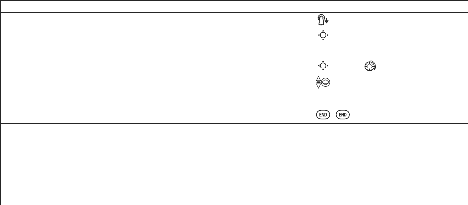
29
GOALS of EXAMPLE STEPS INPUTS for EXAMPLE
Set the second (low) rate throws and
exponential.
A to down position.
C
to D/R.
Repeat steps above to set low rate.
Optional: change dual rate switch
assignment. Ex: elevator to switch
G (10CAG) or E (10CHG) with 3
positions.
C
to SW. to G or E.
G or E to center position.
Repeat steps above to set 3rd rate.
Where next? (Other functions you may wish to set up for your model.)
TRAINER p. 47.
0XOWLSOHZLQJDQGRUWDLOVHUYRVVHHZLQJW\SHVDQGWDLOW\SHVS
Elevator-to-flap, Rudder-to-aileron, flap-to-elevator, and other programmable
mixes p. 68.
Retractable Gear, Flaps on a Switch, Smoke systems, kill switches, and other
auxiliary channel setups. p. 46.
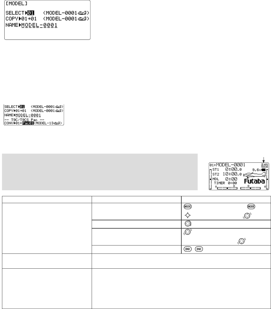
30
$/22.$77+(5$',26)81&7,21667(3%<67(3
MODEL submenu: includes three functions that manage model memory: MODEL SELECT,MODELCOPY and MODELNAME. Since
these functions are all related, and are all basic features used with most models, they are together in the MODEL submenu of
the BASIC menu.
NOTE: When you choose a new model in the MODEL SELECT function, if the new
model is set to the other modulation, you must cycle the transmitter power to change
PRGXODWLRQV,I\RXGRQRWF\FOHWKHSRZHUWKHPRGXODWLRQW\SHZLOOÀDVKRQWKHKRPH
screen to remind you. You are still transmitting on the other modulation until you
affect this change.
GOAL: STEPS: INPUTS:
Select Model #3.
NOTE: This is one of several
functions for which the radio requires
FRQ¿UPDWLRQWRPDNHDFKDQJH
Open BASIC menu, then open MODEL
submenu.
for 1 second. (If ADVANCE, again.)
C
if required to MODEL.
Choose Model #3. to 3.
&RQ¿UP\RXUFKDQJH for 1 second.
Are you sure? displays.
Close.
Confirm proper modulation of new
model memory.
If 2.4GLVÀDVKLQJLQWKHXSSHUULJKWKDQGFRUQHUWKHQWKHQHZPRGHOLVVHWIRU
WKHRWKHUUHFHLYHUW\SH7XUQWKHWUDQVPLWWHURIIRQWRFKDQJHWKHPRGXODWLRQ
Where next? NAME the model: see p. 32.
Change MODEL TYPE (aircraft, heli, glider): see p. 34.
Change modulation (2.4G-10CH or 2.4G-7CH): see p. 35.
Utilize servo REVERSE: see p. 38.
Adjust END POINTs: see p. 39.
Set up IDLE-DOWN and THR-CUT for throttle management: see p. 40, 41.
MODEL SELECT: This function selects which of the 15 model memories in the
WUDQVPLWWHU RU LQ WKH RSWLRQDO CAMPac-... WR VHW XS RU
À\)RUFODULW\WKHPRGHOVQDPHDQGDQLPDJHRILWVW\SHDUHLQGLFDWHGDIWHULWV
number. (Each model memory may be a different model type from the other
memories.)
Note: If you are using the optional CAMPac-16K, your choices in MODEL
SELECT and MODEL COPY will include 16-19, which are the model memories in
the CAMPac. You do not have to COPY from the CAMPac to the transmitter
prior to working with that model.
T9C/T9CS CAMPac data conversion
Although a CAMPac GDWD ZKLFK VDYHG WKH GDWD RI D FRQYHQWLRQDO 7&7&6 WUDQVPLWWHU
cannot be used calling directly, it is possible to use it by the following method, copying to
the model memories of a T10C transmitter. When using the CAMPac, it will be displayed,
for example as "01<-Pac 01." Press DIAL for 1 second in this state and the check display of
"Are you sure?" will appear. Press DIAL again, the data of CAMPac will be copied to model
number"01" of the T10CG transmitter. As for the data of a function added by T10CG, an initial value is set up at this time.
3OHDVHGRQRWIRUJHWWKHFKHFNRIVHWWLQJGDWDEHIRUHDÀLJKW
In addition, refer to p.17 for the initializing method of the CAMPac.
T10CG/T10C CAMPac data compatibility
A CAMPac data which saved the data of a T10CG or conventional T10C transmitter can be used calling directly by a
T10CG and T10C transmitter. As for the data of a function added by T10CG;
(T10C data -> T10CG): an initial value is set up at this time.
7&*GDWD!7&WKHIXQFWLRQGRHVQWZRUNUHJDUGOHVVRILWVGDWD$QGWKHUHLVQRWDQLQÀXHQFHHLWKHU
ÀDVKLQJ
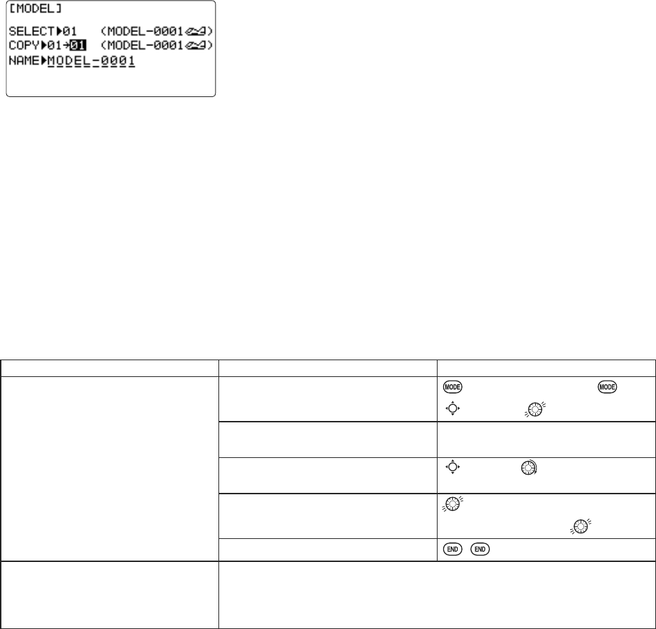
31
MODEL COPYFRSLHVWKHFXUUHQWPRGHOGDWDLQWRDQRWKHUPRGHOPHPRU\LQWKHWUDQVPLWWHURUWKHRSWLRQDO'3..
128K CAMPac). The name of the model memory you are copying into is displayed for clarity.
Notes:
• Any data in the model copied to will be written over and lost, including name,
type and modulation. It cannot be recovered.
• To copy from one T10CG to another, use an optional CAMPac. (Note: The
model may be flown directly off the CAMPac's memory, not requiring re-
copying into the 2nd transmitter. For more information on CAMPacs, please
see p. 10.)
• With the trainer FUNC mode it is not necessary to have the student radio contain
the setup of the aircraft. See TRAINER, p. 47.
'DWDFDQQRWEHFRQYHUWHGIURP8RU=PHPRU\W\SHV,IDCAMPac is installed into the T10CG that has data on it
from another radio type, it will have to be re-initialized which deletes all data.
Examples:
• Start a new model that is similar to one you have already programmed.
• Copy the current model data into another model memory as a backup or before experimenting with new settings.
• Store your model data to an optional CAMPac prior to sending your radio for service.
(GLWDFRS\RI\RXUPRGHO¶VGDWDWRÀ\WKHPRGHOLQGLIIHUHQWFRQGLWLRQVLH+HOLFRSWHUXVLQJKHDYLHUQLJKWEODGHVJOLGHU
in extreme wind; airplane model at extreme altitudes).
• Store your model data to an optional CAMPac to use or copy the settings into a friend's T10CG (A or H) transmitter so
KHFDQÀ\\RXUPRGHORUXVHLWDVDVWDUWLQJSRLQWIRUVHWWLQJXSDVLPLODUPRGHO
GOAL of EXAMPLE: STEPS: INPUTS:
Copy model 3 into model 5.
NOTE: This is one of several
functions for which the radio requires
FRQ¿UPDWLRQWRPDNHDFKDQJH
Open the BASIC menu, then open MODEL
submenu.
for 1 second. (If ADVANCE, again.)
C
to MODEL.
Confirm you are currently using the
proper model memory. (Ex: 3)
If SELECT does not indicate 3, use MODEL
SELECT, p. 25.
Go to MODEL COPY and choose the
model to copy into. (Ex: 5)
C
to COPY. to 5.
&RQ¿UP\RXUFKDQJH for 1 second.
Are you sure? displays. *
Close.
Where next? SELECT the copy you just made: see p. 30.
Rename it (it is currently named exactly the same as the model copied): see p. 32.
Turn off the transmitter and remove the CAMPac for safe keeping or insertion
LQWRDQRWKHUUDGLRWRÀ\
*Radio emits a repeating "beep" and shows progress on screen as the model memory is being copied. Note that if the power switch is turned off prior
to completion, the data will not be copied.
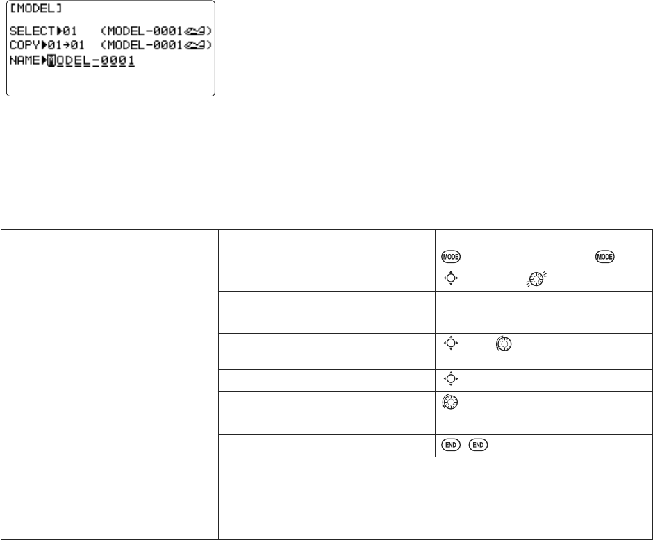
32
MODEL NAME: assigns a name to the current model memory. By giving each model a name that is immediately recognizable,
\RXFDQTXLFNO\VHOHFWWKHFRUUHFWPRGHODQGPLQLPL]HWKHFKDQFHRIÀ\LQJWKHZURQJPRGHOPHPRU\ZKLFKFRXOGOHDGWR
a crash.
Adjustability and values:
• Up to 10 characters long.
• Each character may be a letter, number, blank, or a symbol.
• The default names assigned by the factory are in MODEL-xxxx format
(MODEL-0001 IRU¿UVWPRGHOPHPRU\HWF
NOTE: When you COPY one model memory over another, everything is copied, including the model's name. Similarly, if
you change MODEL TYPE or do a MODEL RESET, the entire memory is reset, including MODEL NAME6RWKH¿UVWWKLQJ\RXZLOO
want to do after you COPY a model, change its type, or start from scratch, is rename the new copy to avoid confusion.
If using multiple frequency modules to be able to transmit on multiple channels, we recommend using the last 2 characters
to indicate the receiver's channel for clarity. For more information on frequency transmission, see p. 8.
GOAL of EXAMPLE: STEPS: INPUTS:
Name model 3 “Cap-232_” (where the
underline represents a blank space.)
Open MODEL submenu. for 1 second. (If ADVANCE, again.)
C
to MODEL.
Confirm you are currently using the
proper model memory. (Ex: 3)
If SELECT does not indicate 3,
perform MODEL SELECT, p. 25.
Go to NAME and change the first
character. (Ex: M to C)
C
to Mto C.
Choose the next character to change.
C
Repeat the prior steps to complete
naming the model.
to a(note: lower case is available)
Repeat.
Close.
Where next? Change the MODEL TYPE to glider or helicopter: see p. 34.
Change modulation [2.4G-10CH or 2.4G-7CH]: see p. 35.
Utilize servo REVERSE: see p. 38.
Adjust servo travel with END POINT: see p. 39.
6HWXSGXDOWULSOHUDWHVDQGH[SRQHQWLDOD/R,EXP): see p. 42.
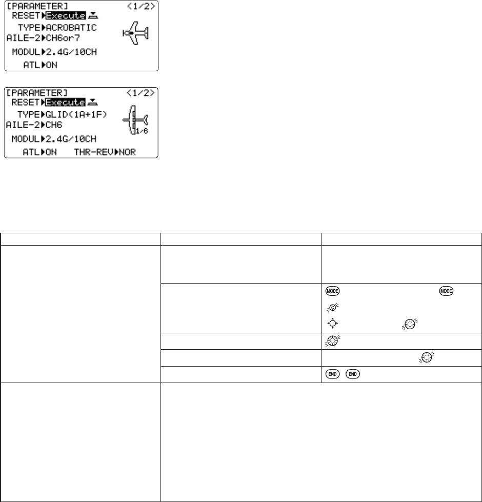
33
PARAMETER submenu: sets those parameters you would likely set once, and then not disturb again.
Once you have selected the correct model you wish to work with, the next step is setting up the proper parameters for this
VSHFL¿FPRGHO
• What is the model's type?
• What type is the receiver’s modulation [2.4G-10CH or 2.4G-7CH]?
• Does the model have a normal throttle on channel 3 or do you need full range
trim on channel 3 (ATL)?
•(
GLID only): The separate THR-REV settings for each model can be set.
First it is important to clear out any old settings in the memory from prior use,
using the MODEL RESET.
MODEL RESET: completely resets all data in the individual model you have
currently selected. Don't worry - there is no way you can accidentally delete all
models in your radio with this function. Only a service center can completely
reset your radio's entire memory at once. To delete each model in your radio's
memory (for example when selling), you must SELECT each model, reset that
memory, then go SELECT the next memory, etc.
Note that when you COPY one model memory into another or change the model's type, you need not delete all existing data
¿UVWE\XVLQJWKLVIXQFWLRQCOPY completely overwrites anything in the existing model memory, including MODEL NAME.
The MODEL TYPE function overwrites all data except name and MODUL.
GOAL of EXAMPLE: STEPS: INPUTS:
Reset model memory 1.
NOTE: This is one of several
functions for which the radio requires
FRQ¿UPDWLRQWRPDNHDFKDQJH
Confirm you are currently using the
proper model memory. (Ex: 1)
On home screen, check model name and
number on top left. If it is not correct,
use MODEL SELECT, p. 30.
Open PARAMETER submenu. for 1 second. (If ADVANCE, again.)
to 2nd page of menu.
C
to PARAMETER.
Reset the Memory. for one second.
&RQ¿UPWKHFKDQJH Are you sure? displays. *
Close.
Where next? Now that the memory is reset, name has returned to the default (Ex:
MODEL-0001).
NAME the model: p. 32.
COPY a different model into this memory: p. 31.
SELECT a different model to edit or delete: p. 30.
Change the MODEL TYPE to glider or helicopter: see p. 34.
Change the receiver modulation [2.4G-10CH or 2.4G-7CH]: see p. 35.
Utilize servo REVERSE: see p. 38.
Adjust servo travel with END POINT: see p. 39.
6HWXSGXDOWULSOHUDWHVDQGH[SRQHQWLDOD/R,EXP): see p. 42.
*Radio emits a repeating “beep” and shows progress on screen as the model memory is being reset. Note that if the power switch is turned off prior to
completion, the data will not be reset.
(ACRO)
(GLID)
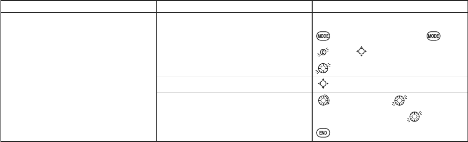
34
MODEL TYPE: sets the type of programming used for this model.
The T10CG has 15 model memories, which can each support:
•one powered aircraft (ACRO PHPRU\ W\SH ZLWK PXOWLSOH ZLQJ DQG WDLO FRQ¿JXUDWLRQV 6HH WZLQ DLOHURQ VHUYRV WZLQ
elevator servos, ELEVON, and V-TAIL for further information.);
WKUHHJOLGHUZLQJW\SHVDJDLQZLWKPXOWLSOHWDLOFRQ¿JXUDWLRQV6HH*OLGHUMODEL TYPE for details, p. 78;
•eight helicopter swashplate types, including CCPM. See Helicopter MODEL TYPE for details, p. 93.
%HIRUHGRLQJDQ\WKLQJHOVHWRVHWXS\RXUDLUFUDIW¿UVW\RXPXVWGHFLGHZKLFKMODEL TYPEEHVW¿WVWKLVSDUWLFXODUDLUFUDIW
(Each model memory may be set to a different model type.) If your transmitter is a T10CAG, the default is ACRO. If it is a
T10CHG, the default is HELI(H1).
ACRO is the best choice for most powered airplanes, but in some circumstances, GLID(2A+1F) may be a better choice. ACRO
is usually a better choice because of functions it offers that the GLID types do not:
•ACRO adds:
•SNAP-ROLL
•AILEVATOR (twin elevator servo support)
•For fuel-powered airplanes: IDLE-DOWN,THR-CUT,THROTTLE-NEEDLE mixing and THROTTLE DELAY programming.
•But ACRO lacks:
•5 seperate conditions for optional setups (STARTSPEEDDISTANCELANDING)
If you are using a glider or heli MODEL TYPE, please go to that chapter now to select the proper model type and support
your model setup. Note that changing MODEL TYPE resets all data for the model memory, including its name.
GOAL of EXAMPLE: STEPS: INPUTS:
Select the proper MODEL TYPE for your
model. Ex: ACRO.
[NOTE: This is one of several functions
that requires confirmation to make a
change. Only critical changes require
additional keystrokes to accept the
change.]
Open the BASIC menu, then open the
PARAMETER submenu.
Turn on the transmitter.
for 1 second. (If ADVANCE, again.)
then
C
to highlight PARAMETER.
to choose PARAMETER.
Go to MODEL TYPE.
C
to TYPE.
Select proper MODEL TYPE.
Ex: ACRO.
&RQ¿UPWKHFKDQJH
Close PARAMETER.
to ACROBATIC. for 1 second.
Are you sure? displays. WRFRQ¿UP
to return to BASIC menu.
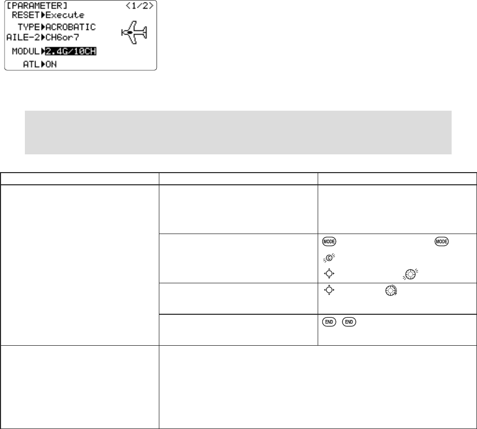
35
Modulation select (MODUL): sets the type of modulation transmitted.
The modulation of your receiver will determine whether you utilize 2.4G-10CH or 2.4G-7CH setting in MODUL during
transmission. Note that you have to turn your transmitter off and back on before a modulation change becomes effective.
Be sure you understand and set the FailSafe (F/S ) settings as you intended (see p. 50).
2.4G-10CH7CH = FASST-2.4GHz system (10CHPRGH7CH mode)
Adjustability:
•2.4G-10CH setting for all Futaba FASST-2.4G Multi-ch mode receivers,
UHJDUGOHVVRIQXPEHURIFKDQQHOVLH5+65+65)65)6
•2.4G-7CH setting for all Futaba FASST-2.4G 7ch mode receivers, regardless of
QXPEHURIFKDQQHOVLH5))5))05)65)6
NOTE: When you change models in MODEL SELECT, if the new model is set to the other modulation type,
\RXPXVWF\FOHWKHWUDQVPLWWHUSRZHUWRFKDQJHPRGXODWLRQV7KHPRGXODWLRQZLOOÀDVKRQWKHKRPHVFUHHQ
to remind you until you do so. See p. 30, MODEL SELECT, for details.
GOAL of EXAMPLE: STEPS: INPUTS:
Change model 1 from 2.4G-10CH to
2.4G-7CH.
Confirm you are currently using the
proper model memory (Ex: 1)
On home screen, check model name and
number on top left and the modulation
on top right. If it is not the correct
model, use MODEL SELECT, p. 30.
Open BASIC menu, then open
PARAMETER submenu.
for 1 second. (If ADVANCE, again.)
to 2nd page of menu.
C
to PARAMETER.
Go to MODUL and change setting.
C
to MODUL. to 2.4G-7CH.
cycle power ÀDVKHVRQVFUHHQ
Close menu and cycle power.
POWER OFF.POWER ON.
Where next? Now that the model is in the proper modulation, the T10CG should communicate
ZLWKWKHUHFHLYHU,ILWGRHVQRWFRQ¿UPWKHW\SHRIWKHUHFHLYHU
Change MODEL TYPEWRJOLGHUKHOLFRSWHUVHHS
Set F/S settings for when 2.4G receiver sees interference: see p. 50.
Utilize servo REVERSE: see p. 38.
Adjust servo travel with END POINT: see p. 39.
6HWXSGXDOWULSOHUDWHVDQGH[SRQHQWLDOD/R,EXP): see p. 42.
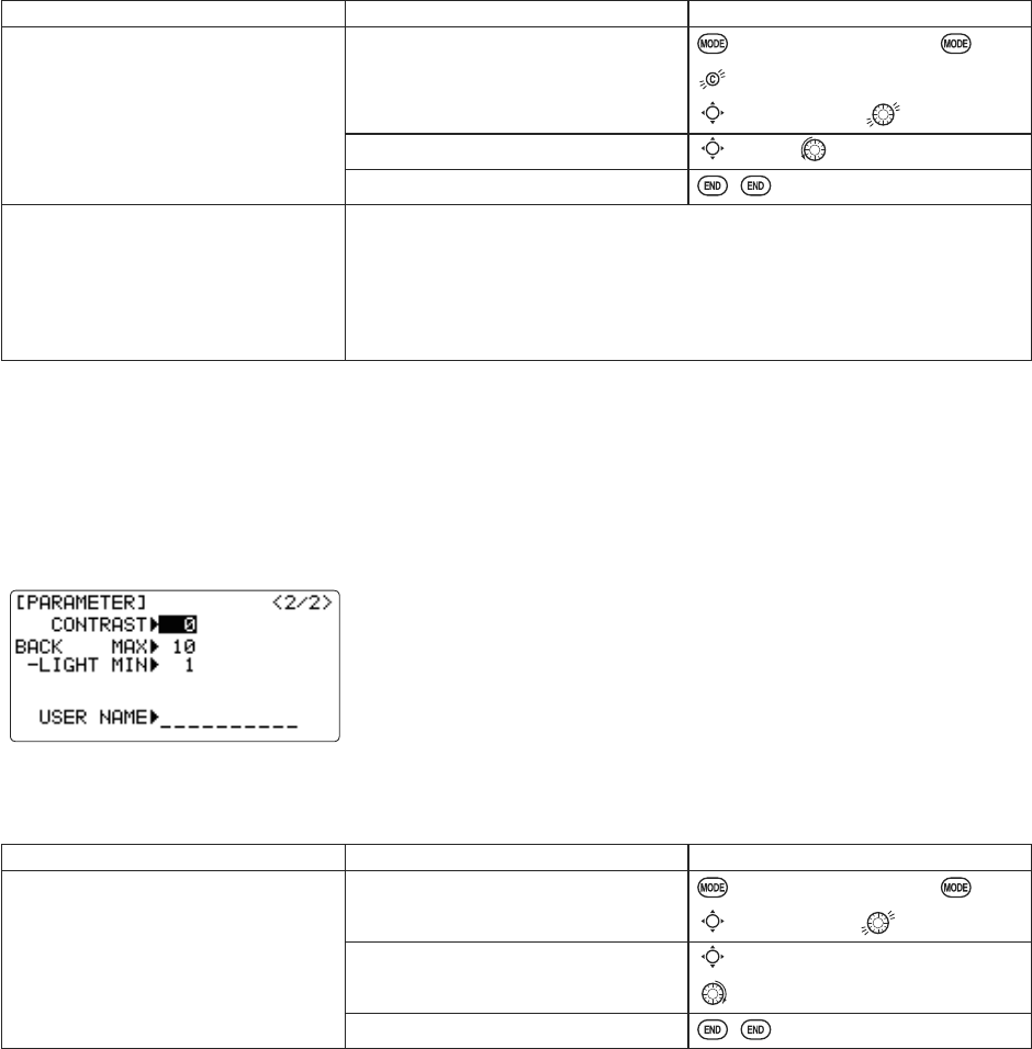
36
Second aileron (AILE-2) (ACROGLID 1A+1FGLID 2A+1F only): changes the default choice for dual aileron servos from
channels 6 (FLAPERON) to channels 5 and 6 or channels 3 and 6 (GLID 1A+1F only), or 7 (AIL-DIF ) to channels 5 and 7.
NOTE: Changing AILE-2 only tells the system which servos to utilize if FLAPERON or AIL-DIF is activated. You still must
activate that function and complete its setup. For details on twin aileron servos, including using AILE-2, see p. 55.
(GLID 1A+1F only): If using channel 3 for second aileron, the receiver's Battery Fail-Safe function does not work.
Adjustable travel limit (
ATL): makes the channel 3 TRIM LEVER (THROTTLE TRIM) effective only at low throttle,
disabling the trim at high throttle. This prevents pushrod jamming due to idling trim changes. This function defaults to ON.
If you are not using channel 3 for throttle, you may want trim operation the same as on all other channels. To do so, set ATL
to OFF. If you need the ATL to be effective at the top of the stick instead of the bottom, reverse the THR-REV setting. Note
that this affects all models in the radio, not just the model you are currently editing. See servo REVERSE, p. 38.
GOAL of EXAMPLE: STEPS: INPUTS:
Change ATL from ON to OFF for battling
robot, tank, airbrake and other channel
3 uses.
Open BASIC menu, then open
PARAMETER submenu.
for 1 second. (If ADVANCE, again.)
to 2nd page of menu.
C
to PARAMETER.
Go to ATL and Change. (Ex: to OFF)
C
to ATL. to OFF.
Close.
Where next? Set up ELEVONIRUWDQNVW\OHFRQWUROWKURWWOHVWHHULQJRQRQH67,&.VHHS
Set up IDLE-DOWN and THR-CUT to adjust channel 3 servo at low-stick: see p. 40.
5HDVVLJQDX[LOLDU\FKDQQHOVH[IURPGLDOWRVZLWFKVOLGHUVHHS
Utilize servo REVERSE: see p. 38.
Adjust servo travel with END POINT: see p. 39.
6HWXSGXDOWULSOHUDWHVDQGH[SRQHQWLDOD/R,EXP): see p. 42.
LCD screen adjustment (CONTRASTBACK-LIGHT):
Adjustability:
The following LCD screen adustments are possible.
• Contrast adjustment
• Backlighting brightness adjustment
CONTRAST: set a LCD contrast from +10(dark) to -10(bright). Also it can be set
from the home screen. See Adjusting Display Contrast, p.16.
BACK-LIGHT MAXVHWDEDFNOLJKWLQJEULJKWQHVVIRUWKHVSHFL¿FSHULRGDSSUR[LPDWHO\VHFRQGVDIWHURSHUDWLQJWKHHGLW
keys. Setting range: OFF(0) to 20(bright).
BACK-LIGHT MINVHWDEDFNOLJKWLQJEULJKWQHVVDIWHUWKHDERYHVSHFL¿FSHULRG6HWWLQJUDQJH2))WRMAX setting.
GOAL of EXAMPLE: STEPS: INPUTS:
Change CONTRAST from 0 to +2. Open BASIC menu, then open
PARAMETER submenu.
for 1 second. (If ADVANCE, again.)
C
to PARAMETER.
Go to CONTRAST and change setting.
(Ex: +2)
C
to CONTRAST.
to +2.
Close.
Throttle Reverse (THR-REV) (GLID only): is a special function that reverse the throttle control, including moving the trim
functionality to the stick's upper half.
The separate THR-REV settings for each model can be set. Default setting depends on the THR-REV setting in the TX SETTING
menu, see p.17.
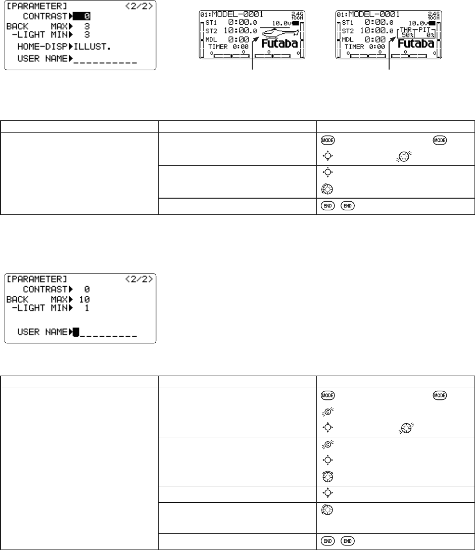
37
Home screen display mode selection (HOME-DISP) (HELI only): selects the display item in the home screen for HELI.
ILLUST: displays the illustration of helicopter in the home screen. (default)
THR/PIT: displays the current throttle and pitch position in the home screen.
GOAL of EXAMPLE: STEPS: INPUTS:
Change the display mode from ILLUST to
THR/PIT.
Open BASIC menu, then open
PARAMETER submenu.
for 1 second. (If ADVANCE, again.)
C
to PARAMETER.
Go to HOME-DISP and change setting.
(Ex: THR/PIT)
C
to HOME-DISP.
to THR/PIT.
Close.
USER NAME: assigns your transmitter's name which is displayed in the home screen.
Adjustability and values:
• Up to 8 characters long.
• Each character may be a letter, number, blank, or a symbol.
• The default name assigned by the factory is "Futaba" logo.
GOAL of EXAMPLE: STEPS: INPUTS:
Name USER NAME “Futaba”. Open BASIC menu, then open
PARAMETER submenu.
for 1 second. (If ADVANCE, again.)
to 2nd page of menu.
C
to PARAMETER.
Go to USER NAME and select the first
character. (Ex: _ to F)
to 2nd page of menu.
C
to USER NAME
to F.
Choose the next character to change.
C
Repeat the prior steps to complete
naming the model.
to u(note: lower case is available)
Repeat.
Close.
THR/PIT mode
ILLUST mode
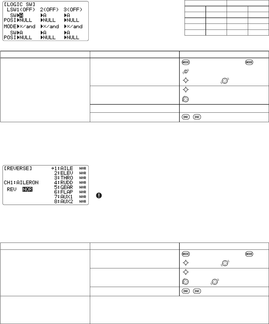
38
Servo reversing (REVERSE): changes the direction an individual servo responds to a CONTROL STICK motion.
[Since channel 9 and 10 are switch only, its servo REVERSE is in the AUX-CH control screen with its switch assignment. See p. 46.]
For CCPM helicopters, be sure to read the section on SWASH AFR (p. 95) before reversing any servos.
Except with CCPM helicopters, always complete your servo reversing prior to any other programming. If you use pre-built
ACROGLID functions that control multiple servos, such as FLAPERON or V-TAIL,
it may be confusing to tell whether the servo needs to be reversed or a setting
in the function needs to be reversed. See the instructions for each specialized
function for further details.
Always check servo direction prior to every flight as an additional
SUHFDXWLRQWRFRQ¿UPSURSHUPRGHOPHPRU\KRRNXSVDQGUDGLRIXQFWLRQ
NOTE: THR-REV is a special function that reverses the entire throttle control, including moving the trim functionality to
the Stick’s upper half. To use THR-REV, turn off the transmitter, hold down the MODE and END keys, turn on. CURSOR
DOWN to THR-REV and turn the DIAL to REV. Turn the transmitter off and back on. This change affects all models in the
radio. (GLID only): The separate THR-REV settings for each model can be set, see p.36.
GOAL of EXAMPLE: STEPS: INPUTS:
Reverse the direction of the elevator
servo.
Open REVERSE function. for 1 second. (If ADVANCE, again.)
C
to REVERSE.
Choose proper channel and set
direction. (Ex: ELE REV)
C
to ELE.
to REV. for 1 second.
Close.
Where next? Adjust servo travel with END POINT: see p. 39.
6HWXSGXDOWULSOHUDWHVDQGH[SRQHQWLDOD/R,EXP): see p. 42.
6HWXSÀLJKWWLPHUVVHHS
Set up trainer functions: see p. 47.
Logic switch selection (LOGIC SW): The various functions in the T10CG can be selected by switch. The Logic switch can
be assigned to the following functions: THR-CUT,IDLE DOWN,AUX-CH,TIMER,PROG. MIX,AIRBRAKE,ELEV-FLAP, and AILE-
FLAP functions. The logic switch can activate functions by two switches combination. The 2 types of logic, either AND or
OR, can be selected.
Adjustability:
• Three logic switches can be used.
(Lsw1,Lsw2, and Lsw3)
• SW(1): Any SWICH A-H or THR-
STKS, SW(2): Any SWICH A-H
• Switch position (POSI)
• Logic mode: AND or OR (MODE)
Logic combination table:
SWITCH LOGIC
SW(1) SW(2) AND OR
off off off off
off on off on
on off off on
on on on on
GOAL of EXAMPLE: STEPS: INPUTS:
Ex: Switch A and B are calculated by
AND logic. (A = down, B = down)
Open BASIC menu, then open LOGIC
SW menu.
for 1 second. (If ADVANCE, again.)
to 2nd page of menu.
C
to LOGIC SW.
Go to POSI and change setting.
(Ex: DOWN)
C
to POSI.
to DOWN.
Next, SW=B,POSI=DOWN Repeat.
Close.
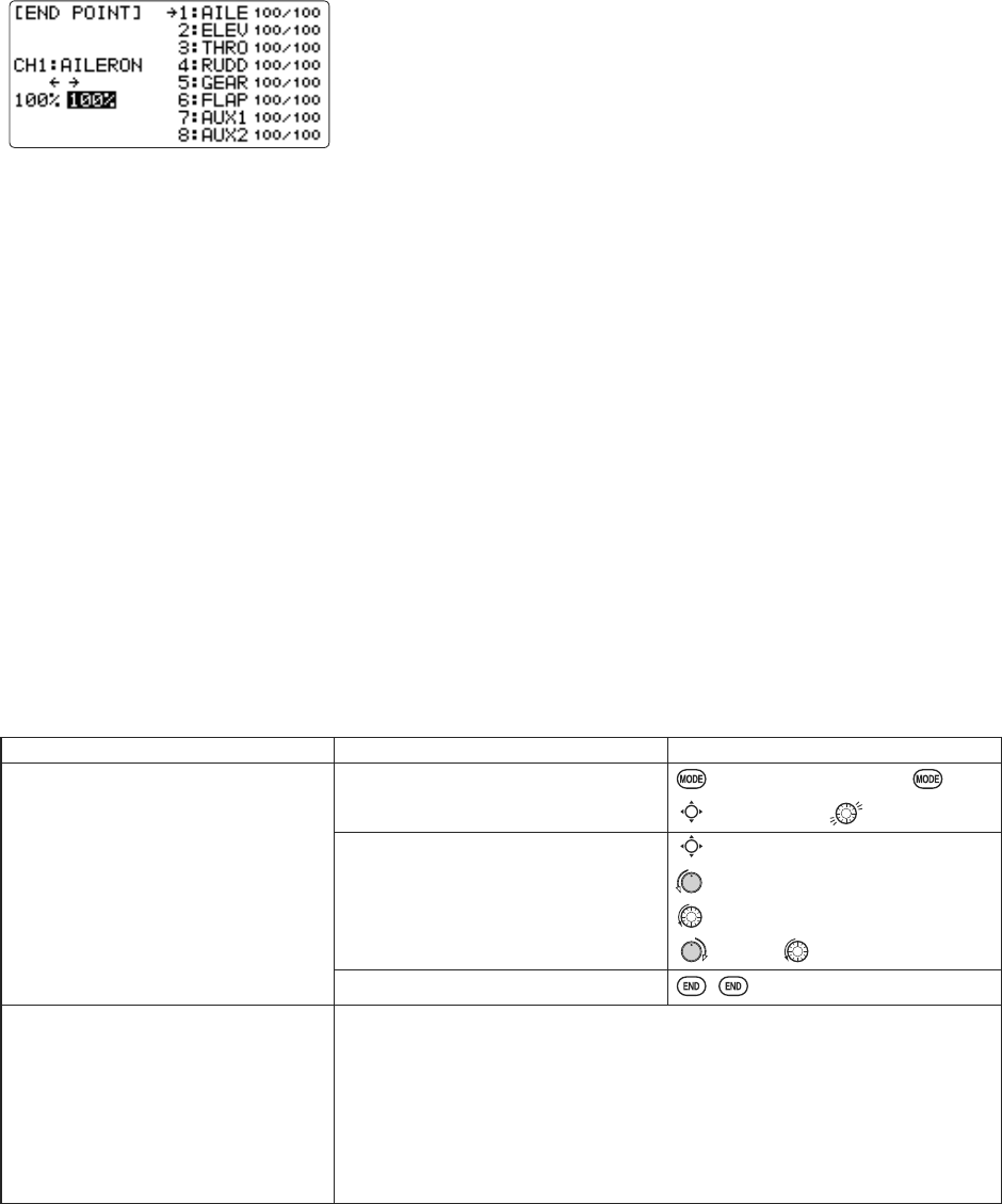
39
End Point of servo travel adjustment (END POINT, also called EPA): the most flexible version of travel adjustment
available. It independently adjusts each end of each individual servo’s travel, rather than one setting for the servo that
affects both directions. Again, for CCPM helicopters, be sure to see SWASH AFR (see p. 95) prior to adjusting end points.
Adjustability:
• Can set each direction independently.
• Ranges from 0% (no servo movement at all) to 140%. At a 100% setting, the
throw of the servo is approximately 40° for channels 1-4 and approximately 55
° for channels 5-8.
• Reducing the percentage settings reduces the total servo throw in that direction.
Examples:
• Adjust the throttle high end to avoid binding at the carburetor, and low end to allow for proper carburetor closure.
$GMXVWÀDSVRXSWUDYHOLVRQO\VXI¿FLHQWIRUVWUDLJKWDQGOHYHOÀLJKWWULPPLQJZLWKIXOOGRZQWUDYHO
•END POINTPD\EHDGMXVWHGWRWRNHHSDVHUYRIURPPRYLQJRQHGLUHFWLRQVXFKDVÀDSVQRWLQWHQGHGWRDOVRRSHUDWHDV
spoilers.
• Retract servos are not proportional. Changing END POINT will not adjust the servo.
END POINT adjusts only the individual servo. It will have no effect on any other servo that is operated in conjunction with
this servo via mix or preset programming such as FLAPERON,AILEVATOR, etc. This is so that each individual servo can be
FDUHIXOO\¿QHWXQHGWRDYRLGELQGLQJDQGRWKHUFRQÀLFWV7RDGMXVWWKHWRWDOWUDYHORIDIXQFWLRQVXFKDVFLAPERON, make
the adjustments in that function's controls. For CCPM helicopters, adjust the total travel of the function, such as collective
pitch, in SWASH AFR.
Adjust the linkage or the END POINT? It is nearly always best to adjust your linkages to get as close as possible prior to
utilizing END POINT. The higher the END POINT setting, the better position accuracy and the more servo power available
at nearly any position (except if using digital servos). Higher END POINT values also mean longer travel time to reach the
desired position, as you are utilizing more of the servo's total travel. (For example, using 50% END POINT would give you
only half the steps of servo travel, meaning every click of trim has twice the effect and the servo gets there in half the
time).
• end point (and moving the linkage) = torque, accuracy, but transit time to get there.
• end point (instead of adjusting linkages) = travel time, but torque, accuracy.
GOAL of EXAMPLE: STEPS: INPUTS:
Decrease the flap servo throw in the
upward direction to 5% to allow
WULPPLQJRI OHYHO ÀLJKW RQO\DQGGRZQ
travel to 85% to prevent binding.
Open END POINT function. for 1 second. (If ADVANCE, again.)
C
to END POINT.
Choose proper channel and move stick
or knob in direction you want to adjust
DQGVHWVHUYRWKURZ([ÀDSXS
C
to FLAP.
ÀDSFRQWURO>GHIDXOWLVVR(A)].
to 5%.*
VR(A). to 85%.
Close.
Where next? Go to SERVOGLVSOD\WRFRQ¿UPGHVLUHGHQGUHVXOWVHHS
0RYHDX[LOLDU\FKDQQHOVWRGLIIHUHQWGLDOVVZLWFKHVVOLGHUVVHHS
Set up IDLE-DOWN and THR-CUTWRVORZFXWWKHHQJLQHVHHS
6HWXSGXDOWULSOHUDWHVDQGH[SRQHQWLDOD/R,EXP): see p. 42.
6HWXSÀLJKWWLPHUVVHHS
Set up trainer functions: see p. 47.
Set up twin aileron servos: see p. 51.
Set up twin elevator servos: see p. 57.
*You can reset to the initial values by pressing the DIAL for one second.
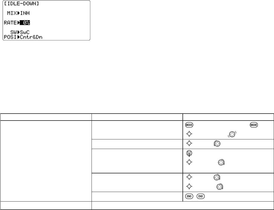
40
Engine idle management: IDLE-DOWN and THR-CUT: functions which work with the digital THROTTLE TRIM to provide
a simple, consistent means of engine operation. No more fussing with getting trim in just the right spot for landings or take
offs! For additional engine adjustments, see THROTTLE-NEEDLE (p. 65) and THROTTLE DELAY (p. 66).
IDLE-DOWN (ACRO only): lowers the engine idle for: sitting on the runway prior to take off, stalls and spins, and landings.
7KHQRUPDOLGOHVHWWLQJLVDOLWWOHKLJKHUIRUHDVLHUVWDUWVDQGVDIHÀLJKWVZLWKOHVVULVNRIGHDGVWLFNV
Important note: The IDLE-DOWN function is not normally used when starting the
engine, and its accidental operation may keep your engine from starting. The
10CG warns that IDLE-DOWN is on when the transmitter is turned on. Be sure to
turn off the function, or override the warning by pressing CURSOR lever if you
intended the function to be on.
7KLVPD\EHDVVLJQHGWRDQ\VZLWFKSRVLWLRQ6RPHPRGHOHUVDFFLGHQWDOO\DVVLJQIDLE-DOWN to one side of a switch
and THR-CUT to the other. There is no “normal” setting to start the engine. By default IDLE-DOWN is set to SWITCH C
center and down. This works well with THR-CUT also on SWITCH CGRZQ7KH6:,7&+XSLVQRUPDOÀLJKWVWDUWLQJ
FHQWHUIRUVORZHUPDQHXYHUVODQGLQJDQGGRZQWRFXWWKHHQJLQH,I\RXDVVLJQIDLE-DOWN or THR-CUT to the spring-
loaded TRAINER SWITCH F (10CAG) or H (10CHG), then use the trainer function, you may risk loss of throttle
control or deadstick for your student.
GOAL of EXAMPLE: STEPS: INPUTS:
Decrease the throttle setting at idle
with the flip of a switch for spins and
landings.
Open BASICmenu, then open IDLE-DOWN
function.
for 1 second. (If ADVANCE, again.)
C
to IDLE-DOWN.
Activate the function.
C
to MIX. to OFF.
With THROTTLE STICK at idle,
adjustthe rate until engine idles as
desired.*
THROTTLE STICK.
C
to RATE.until engine idles as
desired.
Optional: change switch assignment.
Choose desired switch and position.**
C
to SW. to desired SWITCH.
C
to POSI. to desired position.
Close.
Where next? THR-CUT: see p. 41.
*Normally a value of 10- 20%. Secure the fuselage, engine running. Set the THROTTLE STICK to idle. Adjust the IDLE-DOWNUDWHZKLOHÀLSSLQJWKH
switch ON and OFF until the desired idle is achieved. Be sure to throttle up periodically to allow the engine to “clean out” and idle reliably.
*Also LOGIC SW(Lsw1 to 3) may be assigned. Set up LOGIC SW: See p. 38.
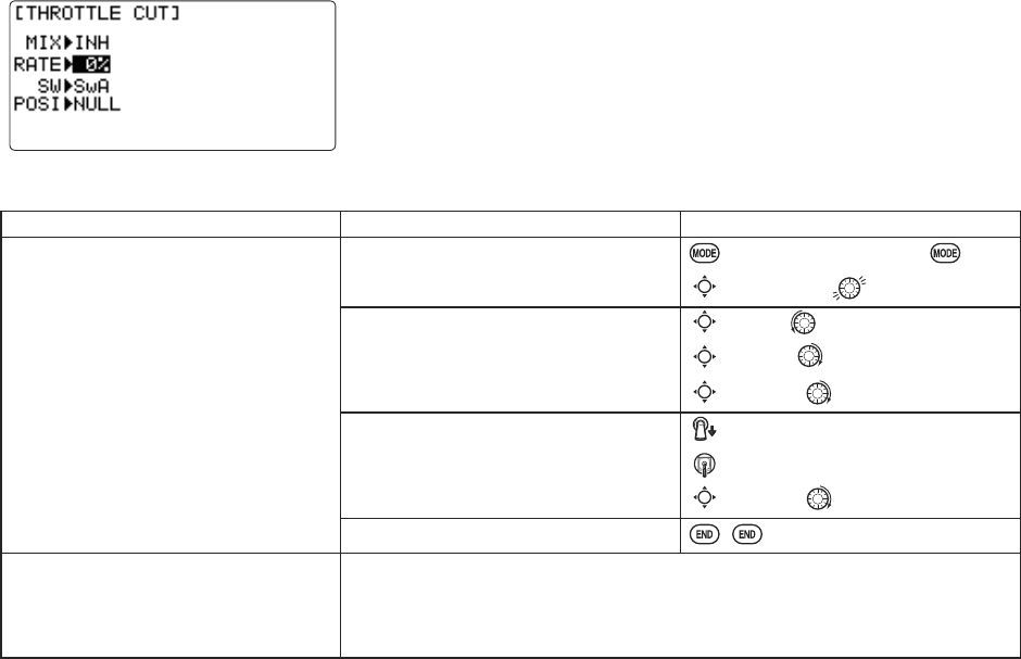
41
Throttle cut (
THR-CUT) (ACROHELI SURYLGHV DQ HDV\ ZD\ WR VWRS WKH HQJLQH E\ ÀLSSLQJ D VZLWFK ZLWKTHROTTLE
STICK at idle). The movement is largest at idle and disappears at high throttle to avoid accidental dead sticks. In HELI,
there is an additional setting, THR-HOLD. See p. 99.
The switch's location and direction must be chosen. It defaults to NULL to avoid
accidentally assigning it to a switch, which might result in an unintentional dead
VWLFNLQÀLJKW3OHDVHVHHIRUIDLE-DOWN and THR-CUT on p. 40.
GOAL of EXAMPLE: STEPS: INPUTS:
Decrease the throttle setting (at idle)
to stop the engine with the flip of a
switch.(Note that you MUST assign
a switch. The default is NULL. We
recommend SWITCH C in the down
position, with IDLE-DOWN programmed
to SWITCH C in the center and down
positions.)
Open BASICmenu, then open THR-CUT
function.
for 1 second. (If ADVANCE, again.)
C
to THR-CUT.
Activate the function. Choose desired
switch, and the position which activates
the function.**
C
to MIX.
C
to SW. to C.
C
to POSI. to DOWN.
With THROTTLE STICK at idle, adjust
the rate until the engine consistently
shutsoff but throttle linkage is not
binding.*
C to down position.
THROTTLE STICK.
C
to RATE. until shuts off.
Close.
Where next? 6HWXSGXDOWULSOHUDWHVDQGH[SRQHQWLDOD/R,EXP): see p. 42.
Set up TRAINER functions: see p. 47.
Set up twin aileron servos: see p. 51.
Set up twin elevator servos: see p. 57.
1RUPDOO\DVHWWLQJRILVVXI¿FLHQW9LHZLQJWKHFDUEXUHWRUEDUUHOXQWLOLWIXOO\FORVHVLVDGHTXDWHWRJHWDQDSSUR[LPDWHVHWWLQJWKHQWHVWZLWK
HQJLQHUXQQLQJWRFRQ¿UP
**Also LOGIC SW(Lsw1 to 3) may be assigned. Set up LOGIC SW: See p. 38.
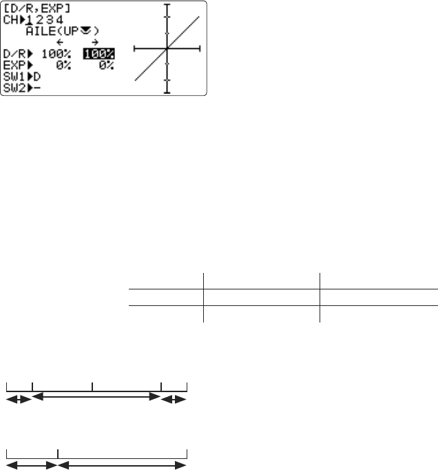
42
'XDOWULSOHUDWHVDQGH[SRQHQWLDOD/R,EXP): assigns adjusted rates and exponential.
Dual/Triple Rates:UHGXFHLQFUHDVH WKHVHUYRWUDYHOE\IOLSSLQJ DVZLWFKRU
(ACROGLID) they can be engaged by any stick position. Dual rates affect the
control listed, such as aileron, not just a single (ex: channel 1) servo. For
example, adjusting aileron dual rate will affect both aileron servos when using
FLAPERON or AIL-DIF, and both aileron and elevator servos’ travel when using
AILEVATOR or ELEVON or a CCPM helicopter.
Activation:
• Any SWITCH, A-H. If you choose a 3-position switch, then that dual rate instantly becomes a triple rate (see example).
• The glider programming offers you the choice of Cond. This option allows you to have a separate rate for each of
condition. (GLID)
• Stick position (ACROGLID([2QUXGGHU\RXQRUPDOO\XVHRQO\WKHFHQWHURI WKH VWLFN PRYHPHQW H[FHSW IRU
H[WUHPH PDQHXYHUV VXFK DV VQDSVVSLQVVWDOOV$V ORQJ DV \RXU 58''(5 67,&. GRHV QRW H[FHHG RI PD[LPXP
throw, the rudder responds at your lower rate, allowing small, gentle corrections. When the stick passes 90% (ie. stall
turn), the rudder goes to high rate’s 90%, which is a MUCH higher amount of travel than your low rate at 89%.)
Ex: (At 100% = 1”) Low Rate = 50% High Rate = 100%
At 89% Low Rate = .45”
At 90% High Rate = .9”
[Note] Only if any stick is chosen by the item of "SW1", a switch can also be chosen by the item of "SW2." When operated
simultaneously, the switch operation has priority over the stick operation. (ACRO)
Adjustability:
• Range: 0 - 140% (0 setting would deactivate the control completely.) Initial
value=100%
• Adjustable for each direction (ACROGLIDLH8SGRZQOHIWULJKW([0RVW
PRGHOVÀ\XSULJKWZLWKRXWDQ\HOHYDWRUWULPEXWUHTXLUHVRPHGRZQHOHYDWRU
ZKHQLQYHUWHG MXVW WR PDLQWDLQ OHYHOÀLJKW%\LQFUHDVLQJWKHGRZQWUDYHOE\
the amount required to hold the model inverted, the model now has equal
travel available from level upright or level inverted.)
Exponential:FKDQJHVWKHUHVSRQVHFXUYHRIWKHVHUYRVUHODWLYHWRWKHVWLFNSRVLWLRQWRPDNHÀ\LQJPRUHSOHDVDQW<RXFDQ
make the servo movement less or more sensitive around neutral for rudder, aileron, elevator, and throttle (except HELI type
- use THROTTLE CURVE instead). (ACRO type—throttle EXP and THROTTLE CURVE can not be activated simultaneously.
Why use expo? Many models require a large amount of travel to perform their best tricks. However, without exponential,
WKH\DUH³WRXFK\´DURXQGQHXWUDOPDNLQJWKHPXQSOHDVDQWWRÀ\DQGPDNLQJVPDOOFRUUHFWLRQVYHU\GLI¿FXOW$GGLWLRQDOO\
by setting different exponentials for each rate, you can make the effectiveness of small corrections similar in each rate, as
in our example below.
The best way to understand exponential is to try it:
• Having made no changes yet in the D/R,EXP screen, move SWITCH D to “down” (toward the AILERON STICK).
• Cursor down to EXP and dial to +100%.
• Move SWITCH D up. Hold the AILERON STICKDWVWLFNDQGPRYHSWITCH D down.
• Notice how much less travel there is.
*RWRVWLFNDQGUHSHDW1RWLFHKRZWKHWUDYHOLVPXFKFORVHULIQRWLGHQWLFDO
High Rate
High Rate
High RateLow Rate
Low Rate
100% 100%
100%30%0%
90% 90%0%
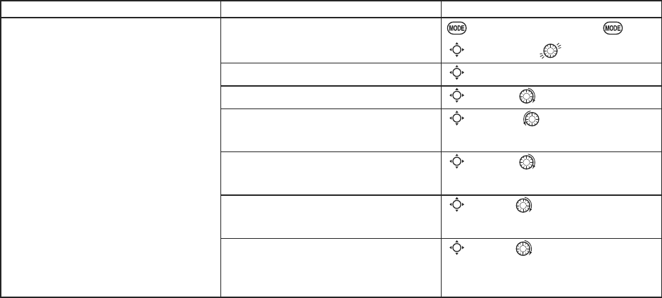
43
Adjustability:
• More sensitive around neutral. (positive exponential, see example)
• Less sensitive around neutral. (negative exponential, see example)
• Adjustable for each direction. (ACROGLID)
For throttle, exponential is applied at the low end to help nitro and gasoline engines have a linear throttle response, so that
HDFKVWLFNLQFUHDVHVHQJLQH530RIWKHDYDLODEOHUDQJH,QPRVWHQJLQHVWKLVUDQJHVIURP
Special note for helicopters: Helicopter model types have just a single rate for each switch position rather than a rate
for each side of the servo’s travel per switch position. Additionally, setting the D/R,EXP for each switch position requires
cursoring back to the No.VHWWLQJDQGFKDQJLQJWKHVZLWFKSRVLWLRQKHUH-XVWÀLSSLQJWKHVZLWFKGRHVQRWDIIHFWWKHVFUHHQ
setting, allowing dual rates to be assigned with idle-up and other features on certain switches, and does not require putting
WKHPRGHOLQWKDWFRQGLWLRQWRPDNHPRGL¿FDWLRQV
Special note for conditions: The helicopter and glider programming offers you the choice of Cond.. This option allows
you to have a separate rate for each of the 3 controls automatically selected when changing conditions, for a total of FIVE
rates available.
Simply change the switch choice to Cond. and then:
(HELI) press the CURSOR LEVER to toggle through the 5 conditions while setting the rates.
(GLID) activate the corresponding condition to edit the rates.
GOAL of EXAMPLE: STEPS: INPUTS:
Set up dual rates and exponential in a
HELI model.
Open D/R,EXP.for 1 second. (If ADVANCE, again.)
C
to D/R,EXP.
Choose channel.
C
to desired channel.
&KRRVH¿UVWVZLWFKSRVLWLRQ
C
to No>. to UP.
Set rate and exponential (Ex: high rate
= 95%, 0% exponential.)
C
to D/R>. to 95%.
&RQ¿UP0% EXP.
Go to 2nd switch position and set rate
and exponential.
C
to No>. to DN.
Repeat above.
Optional: if using a 3 position switch,
set 3rd rate.
C
to No>. to CT.
Repeat above.
Optional: assign dual rates to have one
for each condition.
C
to SW. to COND.
Repeat steps above to adjust for each
condition.
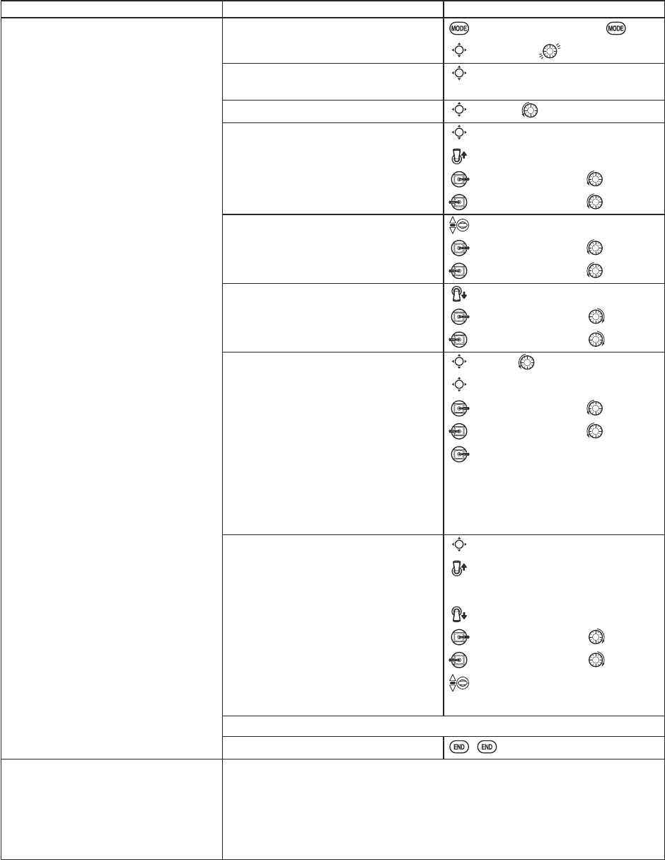
44
GOAL of EXAMPLE: STEPS: INPUTS:
Set up aileron triple rates on SWITCH
C with travel settings of 75% (normal),
25% (slow roll) and 140% (extreme
aerobatics) and exponential settings of
0%, +15%, and -40% respectively.
NOTE: This normal rate has no
exponential so it has a very linear,
normal feel. This slow roll rate has
positive exponential (the opposite of
what most people normally use), which
makes the servos more responsive
around center. This makes the servos
feel the same around center in the
normal and low rates, but still gives a
very slow roll rate at full stick.
The 3D rate (extreme aerobatics) has
a very high distance of travel B nearly
twice that of the normal rate. Therefore,
using a very high negative exponential
setting softens how the servos respond
around center stick. This makes the
servos respond similarly around center
stick for a more comfortable feel.
Many modelers like to set up all 3 triple
rates on a single 3-position switch,
creating a “slow and pretty mode”,
a “normal mode”, and a “wild stunts
mode” all with the flip of a single
switch. To do so, simply set up rates
for all 3 controls and assign all 3 to the
same 3-position switch.
Open D/R,EXP function. for 1 second. (If ADVANCE, again.)
C
to D/R,EXP.
Choose the channel to change
(Ex: aileron is already selected)
C
to desired channel.
Optional: change switch assignment.
C
to SW1. to C.
Confirm switch is in desired position
and set rate. (Ex: up = high rate, 75%).
C
to D/R>.
C to up position.
AILERON STICK. to 75%.
AILERON STICK. to 75%.
Move SWITCH to 2nd rate position and
set this particular rate.
(Ex: center = low rate, 25%).
C to center position.
AILERON STICK. to 25%.
AILERON STICK. to 25%.
Optional: if using a 3 position SWITCH,
move SWITCH to 3rd position and set
this rate (Ex: down = 3D rate, 140%).
C to down position.
AILERON STICK. to 140%.
AILERON STICK. to 140%.
Optional: instead of using a switch,
you can set high rates to be triggered
when the stick moves past a certain
point. To test this, set aileron high rate
to 25%. Now set switch assignment to
AIL (90%). Move AILERON STICK
to the right and notice the huge jump in
travel after the stick moves 90% of its
distance.
C
to SW1. to AILE (90%).
C
to D/R>.
AILERON STICK. to 25%.
AILERON STICK. to 25%.
AILERON STICK and watch
screen graph. See the change?!
You may also change the trigger point
by holding the stick at the desired point,
then pressing and holding the DIAL.
Set each rate’s EXP.
(Ex: 0%, +15%, -40%)
C
to EXP>.
C to up position.
&RQ¿UPEXP reads 0.
C to down position.
AILERON STICK. to +15%.
AILERON STICK. to + 15%.
C to center position.
repeat to set low rate expo to -40%.
Repeat above steps for elevator and rudder.
Close.
Where next? 6HWXSÀLJKWWLPHUVVHHS
Set up TRAINER functions: see p. 47.
Adjust the sensitivity of the trims: see p. 48.
Set up twin aileron servos: see p. 51.
Set up twin elevator servos: see p. 57.
6HWXSSURJUDPPDEOHPL[HVWRPHHW\RXUVSHFL¿FQHHGVVHHS
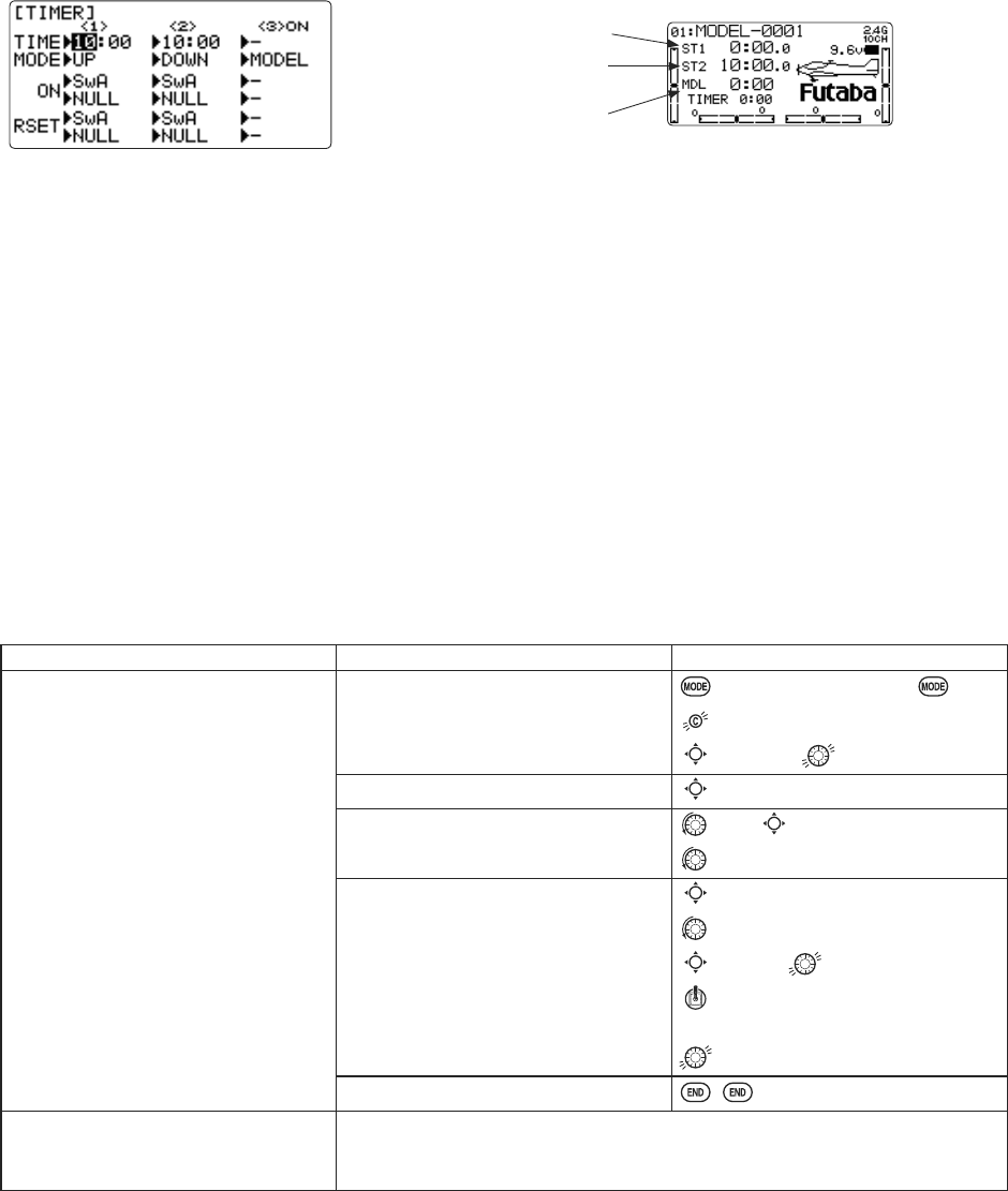
45
TIMER submenu (stopwatch functions): controls three electronic clocks used to keep track of time remaining in a
FRPSHWLWLRQWLPHDOORZHGÀ\LQJWLPHRQDWDQNRIIXHODPRXQWRIWLPHRQDEDWWHU\HWF
Adjustability:
• Count down timer: starts from the chosen time, displays time remaining. If the time is exceeded, it continues to count
below 0.
• Count up timer: starts at 0 and displays the elapsed time up to 99 minutes 59 seconds.
• Count down timer (Stop type): starts from the chosen time, displays time remaining, and stops at 0.
• Model timer: cumulates ON time up to 99 hours 59 minites each model. Once Model timer function is turned off, the
cumulate time will also be reset to "0:00".
• Independent to each model, and automatically updates with model change.
• In either TIMER mode, the timer beeps once each minute. During the last twenty seconds, there's a beep each two seconds.
'XULQJWKHODVWWHQVHFRQGVWKHUHVDEHHSHDFKVHFRQG$ORQJWRQHLVHPLWWHGZKHQWKHWLPHVHOHFWHGLVUHDFKHG83
DOWN TIMER)
• To Reset, choose the desired timer with the CURSOR lever (while at the startup screen), then press and hold DIAL for 1
second.
• Activation by either direction of SWITCH A-H, by THROTTLE STICK (STK-THR) (Using the THROTTLE STICK is
convenient if you are keeping track of fuel remaining, or for an electric, how much battery is left), by LOGIC SWITCH
Lsw1-Lsw3 or by the power SWITCH (PWR SW). Set up LOGIC SW: See p. 38.
• Also the reset switch can be assigned (SWITCH A-H or LOGIC SWITCH Lsw1-Lsw3)
GOAL of EXAMPLE: STEPS: INPUTS:
6HWWLPHUWRFRXQWGRZQPLQXWHV
being controlled by THROTTLE
STICK position. This is utilized to keep
track of actual Throttle on time to better
FRUUHODWHZLWKIXHOEDWWHU\XVDJH
Open BASIC menu, then open TIMER
function.
for 1 second. (If ADVANCE, again.)
to page 2.
C
to TIMER.
Go to TIMER<2>.
C
to 10 (TIMER<2>).
Adjust time to 4 min. 30 sec., count
down.
to 4.
C
to 00 (TIMER<2>).
to 30.
Assign to THROTTLE STICK and set
trigger point.
C
to ON>SwA (TIMER<2>).
to STK THR.
C
to 50%. for 1 second to NULL.
THROTTLE STICK to desired
SRVLWLRQ([VWLFN
for 1 second to set.
Close.
Where next? Adjust END POINTsDIWHU¿UVWÀLJKWWHVWVHHS
$GMXVWDX[LOLDU\FKDQQHODVVLJQPHQWVH[PRYHÀDSVWRDVZLWFKVHHS
Set up TRAINER functions: see p. 47.
TIMER<1>
TIMER<2>
TIMER<3>
(Home screen)
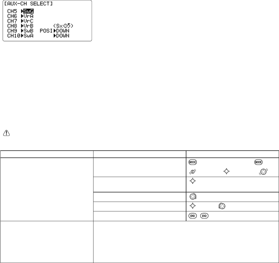
46
Auxiliary channel function (including channel 9-10 controls)(AUX-CHGH¿QHVWKHUHODWLRQVKLSEHWZHHQWKHWUDQVPLWWHU
controls and the receiver output for channels 5-10. Also, the CH9-10 POSI are used to change the CH9-10 servo direction.
Note that the CH9-10 functions are only visible in the AUX-CH screen when 2.4H-10CH modulation is selected. The 8-10th
channels are not supported in 2.4G-7CH modulation.
Adjustability:
• Channels 5-8 may be assigned to any SWITCH (A-H),LOGIC SWITCH
(Lsw1-Lsw3), slider [VR(D) and VR(E)], or knob [VR(A-C)] (for example,
moving flaps to a switch or slider), but not the primary control sticks (use
programmable mixes to do so, p. 68). (GLID 1A+1F only): Channel 6 may be
assigned to Airbrake control stick (STK-ARBK).
• Channel 9-10 may be assigned to any SWITCH (A-H),LOGIC SWITCH
(Lsw1-Lsw3) and the servo direction may be changed.
• Multiple channels may be assigned to the same switch, slider or knob;
• Channels set to "NULL" are only controlled by mixes. (Ex: utilizing 2
channels for 2 rudder servos. See mixes, p. 68.)
•If GYRO SENSE,GOVERNOR, and THR-NEEDLE functions are activated, AUX-CH
settings of related channels become invalid automatically.
Related channels:
GYRO SENSE (ACRO): ch. 5, 7, or 8: see p. 73.
GYRO SENSE (HELI): ch. 5: see p. 107.
GOVERNOR (HELI): ch. 7, or ch. 7 and 8: see p. 108.
THR-NEEDLE (ACROHELI): ch. 8: see p. 65.
Remember that if you assign primary control of a channel to a switch which you later use for other functions (like
GXDOWULSOHUDWHVRUDLUEUDNHVHYHU\WLPH\RXXVHWKDWRWKHUIXQFWLRQ\RXZLOODOVREHPRYLQJWKHDX[LOLDU\FKDQQHO
GOAL of EXAMPLE: STEPS: INPUTS:
$VVLJQÀDSVWRWKHULJKWVOLGHU>VR(E)]
and set channel 7 to NULL in preparation
to use it as a smoke system control (the
smoke system being activated later by a
throttle-to-ch.-7 mix).
Open BASIC menu, then open AUX-CH
function.
for 1 second. (If ADVANCE, again.)
to page 2.
C
to AUX-CH.
Choose the channel to change. (ex: ch.
6.)
C
to Ch 7.
Change primary control. (ex: to slider.) to Vr-E.
Repeat as needed. (ex: ch. 7 to NULL.)
C
to Ch 7. to NULL.
Close.
Where next? Programmable mixes: see p. 68.
6HWXSGXDOWULSOHUDWHVDQGH[SRQHQWLDOD/R,EXP): see p. 42.
Adjust SUB-TRIM of auxiliary channel to adjust center SWITCH position:
see p. 49.
Adjust END POINTs (sets end points of travel even when using a switch):
see p. 39.
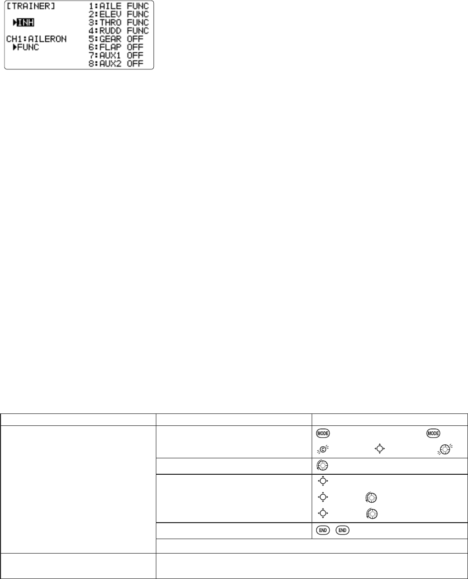
47
TRAINER: for training novice pilots with optional trainer cord connecting 2 transmitters. The instructor has several levels of
controllability.
Adjustability:
•NORM: When the TRAINER SWITCH is ON, the channel set to this mode can
be controlled by the student. The set channel is controlled according to any
programming set at the student's transmitter.
•FUNC: When the TRAINER SWITCH is ON, the channel set to this mode can
be controlled by the student, controlled according to any mixing set at the
instructor's transmitter.
•MIX: When the TRAINER SWITCH is ON, the channel set to this mode can be controlled by both the student and
the instructor, controlled according to any mixing set at the instructor's transmitter. And the student's mixing rate is
adjustable. (default 30%)
[Note] However, it becomes invalid even if it sets up the channel which is not in a student's transmitter. The channel serves
as operation by the instructor's transmitter automatically.
•OFF: The channel set to this mode cannot be controlled by the student even when the TRAINER SWITCH is ON. The set
channel is controlled by the instructor only, even when the TRAINER SWITCH is ON.
• SWITCH: controlled by spring-loaded SWITCH F (10CAG) or H (10CHG) only. Not assignable.
• Compatibility: The 10CG may be master or student with any Futaba transmitter compatible with the cord. Simply plug
the optional trainer cord (For 10CG series, sold separately) into the trainer connection on each transmitter, and follow the
guidelines below.
Examples:
:KHQWKURWWOHFROOHFWLYHDUHVHWWRFUNC,
5-channel helicopter practice is possible
with a 4-channel transmitter.
• Set up the model in a second transmitter,
use NORM mode to quickly and safely check
proper operation of all functions, then allow
WKHVWXGHQWUDGLRWRIXOO\À\WKHPRGHO
•Using NORM mode, set lower throws,
different exponentials, even different
auxiliary channel settings on the student
radio (if it has these features).
• To ease the learning curve, elevator and
aileron may be set to the NORM or FUNC
mode, with the other channels set to OFF
and controlled by the instructor.
GOAL of EXAMPLE: STEPS: INPUTS:
Turn on the TRAINER system and set up
so student has: fully functional control
of aileron and elevator to support
FLAPERON and AILEVATOR; normal
control of rudder to allow lowered
travel; and no throttle channel control
(with the instructor for safety).
Open BASICmenu, then open TRAINER
function.
for 1 second. (If ADVANCE, again.)
to page 2.
C
to TRAINER.
Activate TRAINER.to OFF.
Choose desired channel(s) and proper
training type(s).
C
past AIL and ELE (default OK).
C
to THR, to OFF.
C
to RUD, to NORM.
Close.
7(67VWXGHQWUDGLRIXQFWLRQIXOO\SULRUWRDWWHPSWLQJWRÀ\
Where next? 6HWXSGXDOWULSOHUDWHVDQGH[SRQHQWLDOD/R,EXP) on student 10CG: see p.42.
Reset trims on student 10CG: see p. 48.
Precautions:
• NEVER turn on the student transmitter power.
• ALWAYS set the student transmitter modulation mode to PPM.
As for a T10CG transmitter, PPM signal is always sent by the trainer jack
regardless of the modulation mode.
• BE SURE that the student and instructor transmitters have identical trim
settings and control motions. Verify by switching back and forth while
moving the control sticks.
• Always remove the student transmitter's RF module (if it is a module-
type transmitter).
• When the TRAINER function is active, the snap roll function is deactivated.
Other functions, such as IDLE-DOWN and THR-CUT, which have been
assigned to the same switch, are not deactivated. Always double check
your function assignments prior to utilizing the TRAINER function.
• When you select a different model, the TRAINER function is deactivated in
the current model for safety reasons.
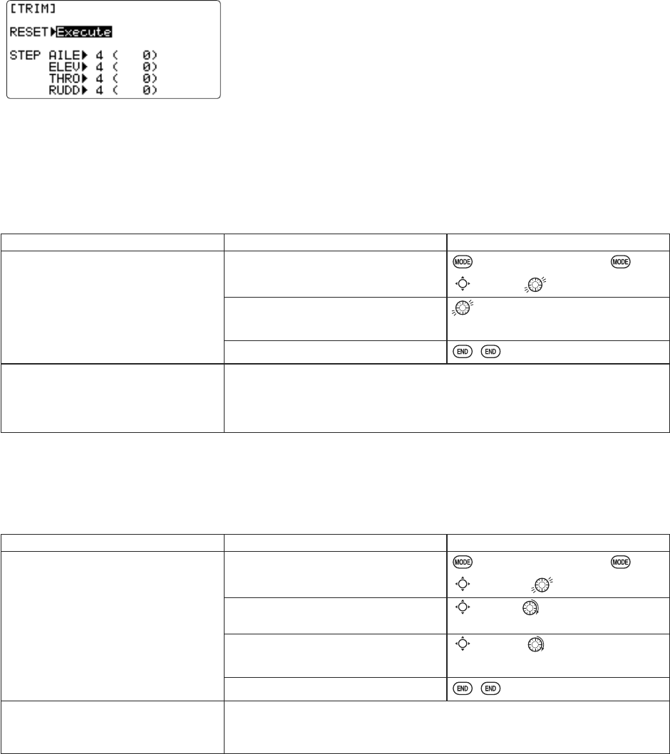
48
TRIM submenu: resets and adjust effectiveness of digital trims.
The 10CG has digital trims which are different from conventional mechanical
trim sliders. Each TRIM LEVER is actually a two-direction switch. Each time
the TRIM LEVER is pressed, the trim is changed a selected amount. When you
hold the TRIM LEVER, the trim speed increases. The current trim position is
graphically displayed on the start up screen. The TRIM submenu includes two
functions that are used to manage the trim options.
HELI models only: OFFSET is available in the idle ups. If OFFSET is inhibited, adjustment of the TRIM LEVERS will adjust
WKHWULPVIRUDOOÀLJKWFRQGLWLRQV,IOFFSET is active, then moving the trims within any one condition will effect only that
condition. See OFFSET, p. 102.
Trim reset (RESET): electronically centers the trims to their default values. Note that the SUB-TRIM settings and the trim
STEP rate are not reset by this command.
GOAL of EXAMPLE: STEPS: INPUTS:
Reset trims to neutral after having
adjusted all linkages.
NOTE: This is one of several
functions for which the radio requires
FRQ¿UPDWLRQWRPDNHDFKDQJH
Open BASICmenu, then open TRIM
submenu.
for 1 second. (If ADVANCE, again.)
C
to TRIM.
Request DQGFRQ¿UPWKHUHVHW.for 1 second.
Beep sounds.
Close.
Where next? Adjust SUB-TRIMs: see p. 49.
Adjust trim rate (STEP): see below.
Adjust END POINTs: see p. 39.
6HWXSGXDOWULSOHUDWHVDQGH[SRQHQWLDOD/R,EXP): see p. 42.
Trim step (STEP): changes the rate at which the trim moves when the TRIM LEVER is activated. It may be set from 1 to
40 units, depending on the characteristics of the aircraft. Most ordinary aircraft do well at about 2 to 10 units. Generally
ODUJHUWULPVWHSVDUHIRUPRGHOVZLWKODUJHFRQWUROWKURZVRUIRU¿UVWÀLJKWVWRHQVXUHVXI¿FLHQWWULPWRSURSHUO\FRUUHFWWKH
PRGHO6PDOOHUWULPVWHSVDUHODWHUXVHGWRDOORZYHU\¿QHDGMXVWPHQWVLQÀLJKW
GOAL of EXAMPLE: STEPS: INPUTS:
Double the sensitivity (larger step) ofthe
AILERON TRIM LEVERS for a first
flight of an aerobatic model to ensure
sufficient range to trim the model for
OHYHOÀLJKW
Open TRIM submenu and choose the
STEP you wish to change. (Ex: aileron)
for 1 second. (If ADVANCE, again.)
C
to TRIM.
Adjust the size of the step.
(Ex: incr. to 8)
C
to AILE. to 8.
Repeat as desired for other channels.
C
to ELEV. to new setting.
Repeat as needed.
Close.
Where next? Adjust sub trims: see p. 49.
Adjust END POINTs: see p. 39.
6HWXSGXDOWULSOHUDWHVDQGH[SRQHQWLDOD/R,EXP): see p. 42.
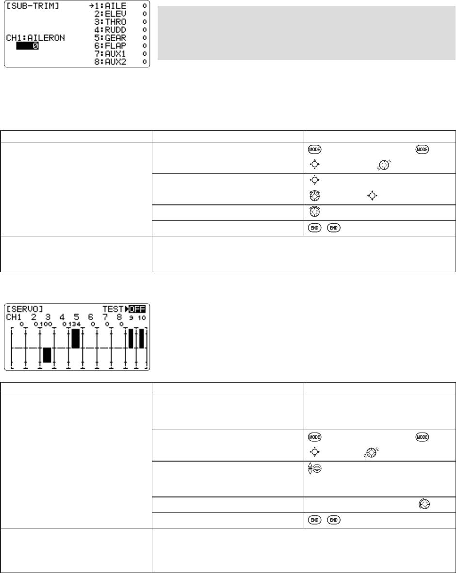
49
SUB-TRIM: makes small changes or corrections to the neutral position of each servo. Range is -120 to +120, with 0 setting,
the default, being no SUB-TRIM.
We recommend that you center the digital trims before making SUB-TRIM
changes, and that you try to keep all of the SUB-TRIM values as small as
possible. Otherwise, when the SUB-TRIMs are large values, the servo's range
of travel is restricted on one side.
The recommended procedure is as follows:
• measure and record the desired surface position;
• zero out both the trims (TRIM RESET menu) and the SUB-TRIMs (this menu);
• mount servo arms and linkages so that the control surface’s neutral is as correct as possible; and
• use a small amount of SUB-TRIMWRPDNH¿QHFRUUHFWLRQV
GOAL of EXAMPLE: STEPS: INPUTS:
$GMXVWWKHÀDSVHUYRVSUB-TRIM untilits
center exactly matches the aileron
servo's center, as they are to work
WRJHWKHUDVÀDSHURQV
Open BASICmenu, then open SUB-TRIM.for 1 second. (If ADVANCE, again.)
C
to SUB-TRIM.
Choose the channel to adjust, andadjust
XQWLOVXUIDFHVPDWFK([ÀDS
C
to FLAP
as needed.
C
to each channel,
Repeat for other channels. as needed.
Close.
Where next? Adjust trim steps: see p. 48.
Adjust END POINTs: see p. 39.
6HWXSGXDOWULSOHUDWHVDQGH[SRQHQWLDOD/R,EXP): see p. 42.
The servo submenu includes two features:
• real-time bar-graph display to demonstrate exactly what commands the
transmitter is sending to the servos. (This can be particularly handy in setting
up models with complicated mixing functions, because the results of each
stick, lever, knob, switch input and delay circuit may be immediately seen.)
VHUYR F\FOH IXQFWLRQ WR KHOS ORFDWH VHUYR SUREOHPV SULRU WR LQÀLJKW IDLOXUHV
(channels 1-8)
GOAL of EXAMPLE: STEPS: INPUTS:
View the result of reassigning channel
6 from VR(A) knob to three-position
SWITCH C.
Cycle the channel 6 servo.
Complete desired programming
function. (Ex: in AUX-CH, move ch. 6 to
SWITCH C)
See AUX-CH for details. (p. 39.)
Open the SERVO function. for 1 second. (If ADVANCE, again.)
C
to SERVO.
Move each control to see exactly how
operating. (Ex: SWITCH C in all
positions)
C to center position.
Note change in position of ch. 6 servo.
Prepare all servos to be cycled and cycle.
Plug in servos. POWER ON.
End cycling and close.
Where next? 6HWXSGXDOWULSOHUDWHVDQGH[SRQHQWLDOD/R,EXP): see p. 42.
Set up desired programmable mixes: see p. 61.
Set up dual aileron servos: see p. 51.
Set up dual elevator servos: see p. 57.
SERVO display and cycle submenu: displays radio's output to channels 1-10.
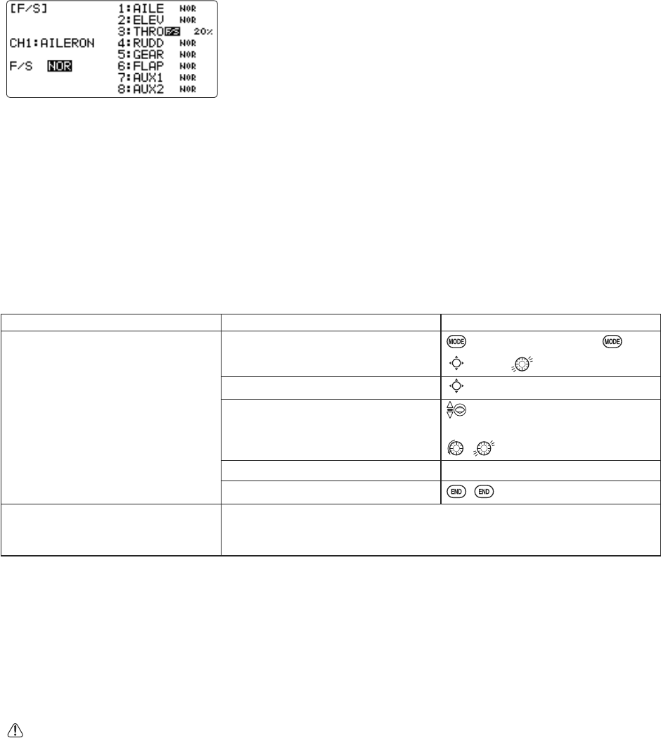
50
FailSafe (loss of clean signal and low receiver battery) submenu (F/S): sets responses in case of loss of signal or low Rx
battery.
FailSafe (F/S): instructs a 2.4G receiver what to do in the event radio interference is received.
Adjustability:
• Each channel may be set independently. (2.4G-7CH mode: ch3 only)
• The NOR (normal) setting holds the servo in its last commanded position.
• The F/S (FailSafe) function moves each servo to a predetermined position.
• NOTE: the setting of the throttle's F/S also applies to the Battery F/S (see
below).
Examples:
• The F/SVHWWLQJLVXVHGLQFHUWDLQFRPSHWLWLRQVWRVSLQWKHDLUFUDIWWRWKHJURXQGSULRUWRÀ\LQJDZD\DQGGRLQJSRWHQWLDO
GDPDJHHOVHZKHUH&RQYHUVHO\PD\DOVREHXVHGWRJRWRQHXWUDORQDOOVHUYRVKRSHIXOO\NHHSLQJWKHSODQHÀ\LQJDVORQJ
as possible.
• Competition modelers often maintain the NOR function so that brief interference will not affect their model's maneuver.
• Set the throttle channel so that the engine idles when there is interference (ACRO7KLVPD\JLYHHQRXJKWLPHWRÀ\DZD\
from and recover from the radio interference and minimize damage if crashed.
• For helicopters, NOR is typically the safest choice.
•
We also recommend setting a gasoline engine's electronic kill switch to the OFF position in the F/S function for safety reasons.
Updating F/S Settings: If you specify a F/S setting, the FailSafe data is automatically transmitted. When you choose the
F/S mode, check that your settings are as desired by turning off the transmitter power switch and verifying that the servos
move to the settings that you chose.
GOAL of EXAMPLE: STEPS: INPUTS:
Change the receiver FailSafe command
for channel 8 (gasoline engine kill
switch) to a preset position.
NOTE: This is one of several
functions for which the radio requires
FRQ¿UPDWLRQWRPDNHDFKDQJH
Open the BASIC menu, then open F/S
function.
for 1 second. (If ADVANCE, again.)
C
to F/S.
Choose Channel to change. (ex: Ch. 8)
C
to Ch 8.
Set and FRQ¿UP fail safe command. that controls channel 8 to desired
OFF position.
for 1 second to store.
Repeat as desired.
Close.
Where next? Read below for information on Battery FailSafe.
Adjust END POINTs to gain proper F/S responses if needed: see p. 39.
Adjust SUB-TRIM to gain proper F/S responses if needed: see p. 49.
Battery FailSafe (F/S): a second battery low warning feature (separate from the transmitter low voltage warning). When
the airborne battery voltage drops below approximately 3.8V, the 2.4G receiver’s battery F/S function moves the throttle
to a predetermined position. When the Battery F/S function is activated, your engine will move to idle (if you haven't set a
position) or a preset position. You should immediately land. You may temporarily reset the Battery F/S function by moving
the THROTTLE STICK to idle. You will have about 30 seconds of throttle control before the battery function reactivates.
Adjustability:
•NOR F/S setting for throttle results in Battery F/S going to the servo position reached by moving THROTTLE STICK to
the bottom with TRIM LEVER centered;
•F/S position setting for throttle results in Battery F/S also going to the same throttle servo position as the regular F/S.
If using a 6V (5-cell) receiver battery, it is very likely that your battery will be rapidly running out of charge before
battery FailSafe takes over. It is not a good idea to count on battery FailSafe to protect your model at any time, but
especially when using a 5-cell battery.
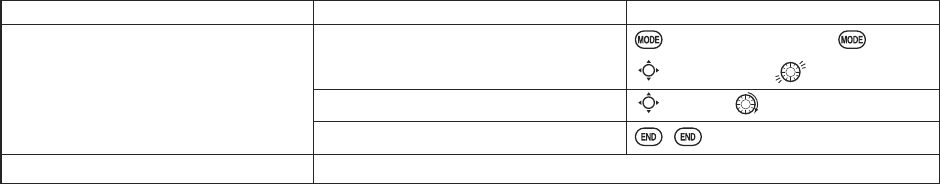
51
ACRO ADVANCE MENU FUNCTIONS:
Aircraft wing types (ACROGLID):
There are 3 basic wing types in aircraft models:
• Simple. Model uses one aileron servo (or multiple servos on a Y-harness into a single receiver channel) and has a tail.
This is the default setup and requires no specialized wing programming.
• Twin Aileron Servos. Model uses 2 aileron servos and has a tail. see Twin Aileron Servos.
• Tail-less model (flying wing). Model uses 2 wing servos working together to create both roll and pitch control. see
ELEVON.
Twin Aileron Servos (with a tail) (ACROGLID): Many current generation models use two aileron servos, plugged into two
VHSDUDWHUHFHLYHUFKDQQHOV,I\RXUPRGHOLVDÀ\LQJZLQJZLWKRXWVHSDUDWHHOHYDWRUVVHHELEVON, p. 56.)
%HQH¿WV
• Ability to adjust each servo's center and end points for perfectly matched travel.
• Redundancy, for example in case of a servo failure or mid-air collision.
• Ease of assembly and more torque per surface by not requiring torque rods for a single servo to drive 2 surfaces.
+DYLQJPRUHXSDLOHURQWUDYHOWKDQGRZQWUDYHOIRUVWUDLJKWHUUROOVDLOHURQGLIIHUHQWLDOVHHJORVVDU\IRUGH¿QLWLRQ
8VLQJWKHWZRDLOHURQVQRWRQO\DVDLOHURQVEXWDOVRDVÀDSVLQZKLFKFDVHWKH\DUHFDOOHGÀDSHURQV
• Set a negative percentage to reverse the operation of one of the servos.
Options:
•FLAPERON:
•Uses CH6 for the second servo.
$OORZVÀDSDFWLRQDVZHOODVDLOHURQDFWLRQIURPWKHDLOHURQV
•Provides FLAP-TRIMIXQFWLRQWRDGMXVWWKHQHXWUDOSRLQWRIWKHÀDSHURQVIRUOHYHOÀLJKW
•Also allows aileron differential in its own programming (instead of activating AIL-DIFF).
• Aileron Differential (AIL-DIFF):
•Uses CH7 for the 2nd servo.
/HDYHV&+&+IUHHIRUÀDSRSHUDWLRQVXFKDVÀDSHURQDQGÀDSDFWLRQWRJHWKHULQAIRBRAKE. (see p. 63).
•Allows for more up aileron travel than down for straighter rolls.
You will need to choose which of FLAPERON or AIL-DIFF is the better choice for your model's setup. If you need the ailerons
WRDOVRRSHUDWHDVÀDSV\RXPRVWOLNHO\ZDQWWRXVHFLAPERON,I\RXUPRGHOKDVDLOHURQVHUYRVDQGÀDSVWKHQAIL-DIFF
is probably the easiest choice. (For details on setting up a complex aerobatic plane, such as one with 4 wing servos using
IXOOVSDQDLOHURQVDQGIXOOVSDQÀDSVDVZHOODVAIRBRAKEFURZDQGRWKHUIHDWXUHVSOHDVHYLVLWRXU)$4DWZZZIXWDEDUF
com\faq\. Many other setup examples are also available at this location.)
NOTE: Only one of the three wing-type functions (FLAPERON,AIL-DIFF, and ELEVON) can be used at a time. All three
IXQFWLRQVFDQQRWEHDFWLYDWHGVLPXOWDQHRXVO\7RDFWLYDWHDGLIIHUHQWZLQJW\SHWKH¿UVWPXVWEHGHDFWLYDWHG
GOAL of EXAMPLE: STEPS: INPUTS:
De-activate FLAPERON so that AIL-DIFF or
ELEVON can be activated.
Open the FLAPERON function. for 1 second. (If BASIC, again.)
C
to FLAPERON.
De-activate the function.
C
to MIX. to INH.
Close function.
Where next? Set up AILE-DIFF (see p. 54) or ELEVON (see p. 56).
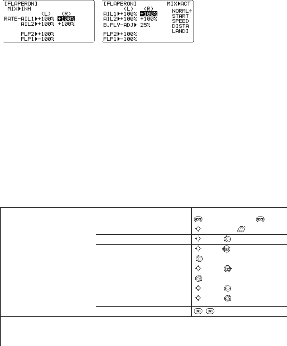
52
Using FLAPERON (ACROGLID 1A+1F ):
The FLAPERONPL[LQJIXQFWLRQXVHVRQHVHUYRRQHDFKRIWKHWZRDLOHURQVDQGXVHVWKHPIRUERWKDLOHURQDQGÀDSIXQFWLRQ
)RUÀDSHIIHFWWKHDLOHURQVUDLVHORZHUVLPXOWDQHRXVO\2IFRXUVHDLOHURQIXQFWLRQPRYLQJLQRSSRVLWHGLUHFWLRQVLVDOVR
performed.
[Note] When changing the polarity of a rate, "change rate dir?" is displayed for a check. Please set up after
pressing DIAL for 1 second and canceling an alarm display. (GLID only)
Once FLAPERONLVDFWLYDWHGDQ\WLPH\RXSURJUDP&+RUÀDSLHELEVATOR-FLAP mixing), the radio commands both
VHUYRVWRRSHUDWHDV ÀDSV7KHDPRXQWRIWUDYHODYDLODEOH DV ÀDSV LV LQGHSHQGHQWO\DGMXVWDEOHLQFLAPERON. A trimming
feature is also available (see FLAP-TRIM WR DGMXVW ERWK QHXWUDO SRVLWLRQV WRJHWKHU IRU VWUDLJKWDQGOHYHO ÀLJKW RU VOLJKW
LQFUHDVHVGHFUHDVHVRIWKHÀDSDQJOHEND POINT and SUB-TRIM both still adjust each servo individually.
Adjustability:
• Each aileron servo's up travel can be set separate from its down travel, creating aileron differential. (See example).
(DFKDLOHURQVHUYRVWUDYHOZKHQDFWXDWHGDVDÀDSLVVHSDUDWHO\DGMXVWDEOH
• The separate FLAPERON settings for each condition can be set. (GLID)
127($FWLYDWLQJÀDSHURQVRQO\PDNHVWKHDLOHURQVZRUNDVDLOHURQVDQGWHOOVWKHUDGLRKRZIDU\RXZDQWWKHPWRPRYH
DVÀDSV,)\RXWKHQDFWLYDWHRWKHUSURJUDPPLQJWKDWPRYHVWKHPDVÀDSV
FLAP-TRIMLVWKHÀDSWULPPLQJIHDWXUHWKDWDOORZVWKHÀDSVWRPRYHLQUHDFWLRQWRWKHFKDQQHOFRQWURO,WLVPHDQWRQO\
IRUWULPPLQJWKHÀDSVFHQWHUEXWFDQDOVREHXVHGDVIXOOÀDSFRQWURO6HHS
AIRBRAKELVDIHDWXUHWKDWGURSVÀDSHURQVDVÀDSDQGDOVRFRPSHQVDWHVZLWKHOHYDWRULIGHVLUHG6HHS
ELEVATOR-FLAPZRXOGDGGHOHYDWRUPL[LQJLQWRWKHÀDSPRYHPHQWIURPWKHÀDSGLDODIWHUFLAP-TRIM is activated.
GOAL of EXAMPLE: STEPS: INPUTS:
Activate twin aileron servos, FLAPERON.
Input 10% less down travel than up
travel (aileron differential) within the
FLAPERON programming. (Decrease right
aileron is down travel to 90%, decrease
left aileron's down travel to 90%.)
$GMXVWWRWDOÀDSWUDYHODYDLODEOHWR
of aileron travel available.
Open the FLAPERON function. for 1 second. (If BASIC, again.)
C
to FLAPERON.
Activate the function.
C
to MIX. to ACT.
Optional: adjust the up/down travel
separately for the 2 servos.(Ex: 90%
down.)
C
to AIL1.AILERON STICK.
to 90%.
C
to AIL2.AILERON STICK.
to 90%.
Optional: adjust the aileron's travel so
WKH\PRYHDVÀDSV([HDFKVHUYR ÀDS
travel to 50%.)
C
to FLP2. to +50%.
C
to FLP1. to -50%.
Close menu.
Where next? Set FLAP-TRIM: see p. 53.
Set up AIRBRAKE mix: see p. 63.
0L[ÀDSHURQVÀDSPRWLRQWRDQRWKHULQERDUGÀDSSOXJJHGLQWRDX[VHHS
9LHZDGGLWLRQDOPRGHOVHWXSVRQWKHLQWHUQHWZZZIXWDEDUFFRPIDT
* If you receive an error message that OTHER WING MIXING IS ON, you must deactivate AIL-DIFF or ELEVON. see p. 51.
(GLID 1A+1F)(ACRO)
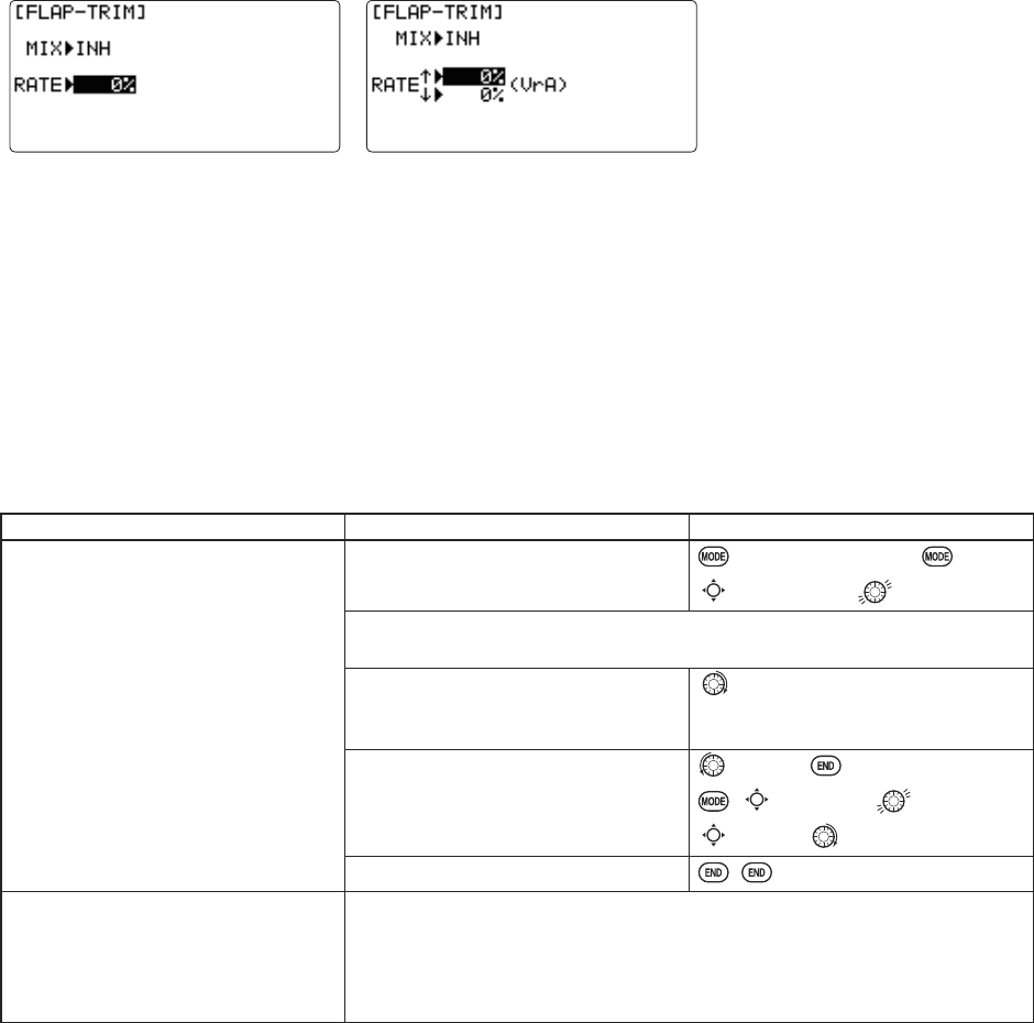
53
Using FLAP-TRIM FDPEHUWRDGMXVWÀDSHURQV (ACROGLID )
FLAP-TRIM assigns the primary flaperon control [defaults to VR(A)] to allow trimming in flight of the flap action of
ÀDSHURQV1RWHHYHQLIFLAP-TRIM is made active with AIL-DIFF, it will not have any effect. The ONLY function that allows
FRQWURORIWKHDLOHURQVDVÀDSVLQWKHAIL-DIFFFRQ¿JXUDWLRQLVAIRBRAKE.) Most modelers use AIRBRAKE, or programmable
PL[HVWRPRYHWKHÀDSVWRDVSHFL¿HGSRVLWLRQYLDPRYHPHQWRIDVZLWFK
FLAP-TRIMPD\DOVREHXVHGDVWKHSULPDU\ÀDSFRQWUROLQÀLJKW%\GRLQJVR\RXFDQDVVLJQ&+WRDSRVLWLRQVZLWFK
ZLWK D VSRLOHURQ QHXWUDO DQG IODSHURQ SRVLWLRQ DQG HYHQ DGMXVW WKH SHUFHQWDJH WUDYHOHG DV IODSHURQVSRLOHURQ E\
changing the Flap Trim travel. (Note that there is only one setting, not independent settings for up and down travel.)
GOAL of EXAMPLE: STEPS: INPUTS:
Add FLAP-TRIM to allow the model's
DLOHURQVWREHWULPPHGWRJHWKHUDVÀDSV
at any time during the flight,with a
maximum travel of 5%RI WKHWRWDOÀDS
travel set in FLAPERON.
Open the FLAP-TRIM function. for 1 second. (If BASIC, again.)
C
to FLAP-TRIM.
The function is automatically activated with FLAPERON; however, the default
travel is 0.
Adjust the travel available to the
flaperons when turning the CH6
DIAL.(Ex: 5%).
to 5%.
Optional: Use as total flap control.
Reassign CH6 is primary control in
AUX-CHWR\RXUGHVLUHGÀDSFRQWURO
(Ex: right slider)
to 50%.
C
to AUX-CH.
C
to CH6. to Vr-E.
Close menu.
Where next? Adjust individual servo's SUB-TRIMs: see p. 49 and END POINTs: see p. 39.
Set up AIRBRAKE mix: see p. 63 and ELEV-FLAP mix: see p. 62.
0L[ÀDSHURQVÀDSPRYHPHQWWRDQDGGLWLRQDOLQERDUGÀDSSOXJJHGLQWRDX[
see p. 61.
View additional model setups on the internet: www.futaba-rc.com\faq\.
(GLID)(ACRO)
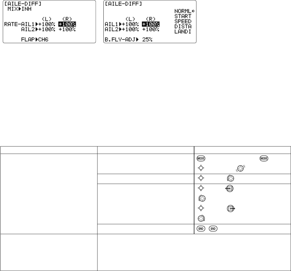
54
Using Aileron Differential (AILE-DIFF)(ACROGLID 2A+1FGLID 2A+2F):
$LOHURQGLIIHUHQWLDOLVSULPDULO\XVHGRQRUVHUYRZLQJVZLWKRQHVHUYRVRSHUDWLQJLQERDUGÀDSVRQ&+RU&+
& CH6, and AILE-DIFF controlling proper aileron operation of 2 aileron servos, plugged into CH1 and CH7. The ailerons
FDQQRWEHPRYHGOLNHÀDSVZKHQXVLQJAILE-DIFF, except if using AIRBRAKE (see p. 63.) (Note that even if you make FLAP-
TRIM active while using AILE-DIFF, it will not have any effect. ONLY AIRBRAKEFRQWUROVWKHDLOHURQVDVÀDSVLQWKHAILE-DIFF
FRQ¿JXUDWLRQ
>1RWH@ :KHQ FKDQJLQJ WKH SRODULW\ RI D UDWH LQ FDPEHUÀDS FKDQJH UDWH GLU" LV GLVSOD\HG IRU D FKHFN
Please set up after pressing DIAL for 1 second and canceling an alarm display. (GLID only)
)/$3IXQFWLRQDOORZV\RXWRVHWXSRUVHUYRVIRUÀDSDFWLRQ
• The separate AILE-DIFF settings for each condition can be set. (GLID only)
GOAL of EXAMPLE: STEPS: INPUTS:
Activate twin aileron servos using AIL-
DIFF.
Note that the function defaults to no
difference in down travel vs. up travel.
If you want differential travel, simply
adjust each side. (Ex: 90%)
Open the AIL-DIFF function. for 1 second. (If BASIC, again.)
C
to AIL-DIFF. *
Activate the function.
C
to MIX. to ACT.
2SWLRQDODGMXVWWKHXSGRZQWUDYHO
separately for the 2 servos.
(Ex: adjust to 90%.)
C
to AIL1.AILERON STICK.
to 90%.
C
to AIL2.AILERON STICK.
to 90%.
Close menu.
Where next? Adjust individual servo's SUB-TRIMs: see p. 49 and END POINTs: see p. 39.
Set up AIRBRAKE mix: see p. 63.
Set up ELEV-FLAPPL[RQO\LIPRGHOKDVDÀDSVHUYRLQ&+VHHS
Set up SNAP-ROLL Function: see p. 59.
View additional model setups: www.futaba-rc.com\faq\.
*If you receive an error message that OTHER WING MIXING IS ON, you must deactivate ELEVON or FLAPERON. See p. 51.
(GLID 2A+1FGLID 2A+2F)(ACRO)
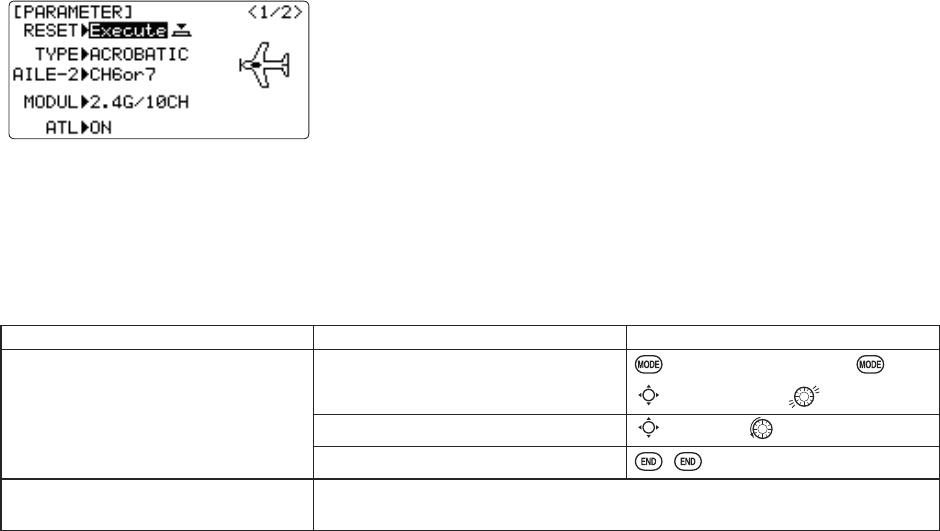
55
Using Twin Aileron Servos, AILE-2 (ACROGLID ):
AILE-2 only tells the radio that you are using CH5 and CH6 (FLAPERON), or CH5
and CH7 (AIL-DIFF), not CH6 or CH7, as the second servo in FLAPERON or AILE-
DIFF. You still must activate and set up the FLAPERONAILE-DIFF function.
Note that selecting CH6&5 or CH7&5 does NOT free up CH6 or CH7 to be used for other functions when using a receiver
with more than 5 channels. Both 5 and 6 (FLAPERONAILE-DIFF) are dedicated to the FLAPERON or AILE-DIFF programming.
>7KLVLVEHQH¿FLDOZLWKIRXUDLOHURQVHUYRVWKDWQHHGWRKDYHWKHLUHQGSRLQWVRUVXEWULPVVHWVHSDUDWHO\&+&+DQG
CH6 are already fully set up to operate as ailerons. Mix CH7 or CH8 (the second aileron servo on the other side) into
ailerons to function properly.]
GOAL of EXAMPLE: STEPS: INPUTS:
Adjust the second aileron servo output
from CH6or7 to channels CH6&5.
Allows twin aileron servo operation
with a 5-channel receiver.
Open the PARAMETER submenu. for 1 second. (If ADVANCE, again.)
C
to PARAMETER.
Select AILE-2 and change to CH6&5.
C
to AILE-2. to CH6&5.
Close menu.
Where next? Finish setting up FLAPERON or AILE-DIFF. see Twin Aileron Servos: p. 51.
View additional model setups on the internet: www.futaba-rc.com\faq\
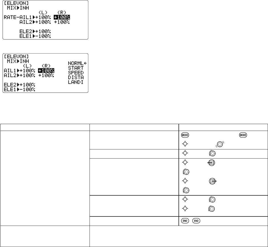
56
Aircraft tail types (ACROGLID):
There are 4 basic tail types in aircraft models:
• Simple. Model uses one elevator servo and one rudder servo (or multiple servos on a Y-harness). This is the default.
• Dual Elevator servos. Model uses 2 elevator servos. see AILEVATOR (ACRO) see p. 57.
•
Tail-less model. Model uses 2 wing servos together to create roll and pitch control. see ELEVON(ACROGLID 1A+1F). see p. 56.
•
V-TAIL. Model uses 2 surfaces, at an angle, together to create yaw and pitch control. see V-TAIL (ACROGLID). see p. 58.
Note: Only one of the three tail-type functions (AILEVATOR,V-TAIL, and ELEVON) can be used at a time. The radio provides a
ZDUQLQJDQGZLOOQRWDOORZWKHDFWLYDWLRQRIDQRWKHUWDLOW\SHXQWLOWKH¿UVWLVGHDFWLYDWHG$QHUURUPHVVDJHRIOTHER WING
MIXING IS ON will display. (See the wing type example on page 51.)
Using ELEVON(ACROGLID 1A+1FXVHGZLWKGHOWDZLQJVÀ\LQJZLQJVDQGRWKHUWDLOOHVVDLUFUDIWWKDWFRPELQHDLOHURQDQG
HOHYDWRUIXQFWLRQV XVLQJ WZR VHUYRV RQHRQ HDFK HOHYRQ7KH DLOHURQHOHYDWRU UHVSRQVHV RIHDFK VHUYR FDQ EH DGMXVWHG
independently. This is also popular for ground model use, such as tanks, which drive two motors together for forward, and
RQHPRWRUIRUZDUGRQHEDFNZDUGIRUWXUQLQJ
Adjustability:
• Requires use of CH1 and CH2.
• Independently adjustable aileron travel allows aileron differential.
• Independently adjustable elevator travel allows for differences in up vs. down
travel.
• The separate ELEVON settings for each condition can be set. (GLID only)
[Note] When changing the polarity of a rate, "change rate dir?" is displayed for
a check. Please set up after pressing DIAL for 1 second and canceling an alarm
display. (GLID only)
NOTE: If ELEVON is active, you cannot activate FLAPERON, AILE-DIFF, or
AILEVATOR. An error message OTHER WING MIXING IS ON displays and you must
deactivate the last function to activate ELEVON.
127(%HVXUHWRPRYHWKHHOHYDWRUDQGDLOHURQVWLFNVWRIXOOGHÀHFWLRQGXULQJ
setup. If large travels are specified, when the AILERON and ELEVATOR
STICKS are moved at the same time the controls may bind or run out of travel.
(For details on setting up a complex aerobatic plane, please visit www.futaba-
rc.com\faq\. Many other setup examples are also available at this location. )
GOAL of EXAMPLE: STEPS: INPUTS:
Activate ELEVON.
Adjust aileron down travel to 90% of up
travel, creating aileron differential.
Open the ELEVON function. for 1 second. (If BASIC, again.)
C
to ELEVON.
Activate the function.
C
to MIX. to ACT.
Optional: adjust the up/down travel
separately for the servos as ailerons.
(Ex: down to 90%.)
C
to AIL1.AILERON STICK.
to 90%.
C
to AIL2.AILERON STICK.
to 90%.
Optional: adjust the elevator travel of
each servo. (Ex: right servo elev. travel
to 98%, left to 105%.)
C
to ELE2. to 98%.
C
to ELE1. to 105%.
Close menu.
Where next? Adjust individual servo's SUB-TRIMs: see p. 49 and END POINTs: see p. 39.
6HWXSGXDOWULSOHUDWHVDQGH[SRQHQWLDOD/R,EXP): see p. 42.
View additional model setups on the internet: www.futaba-rc.com\faq.html
(GLID 1A+1F)
(ACRO)
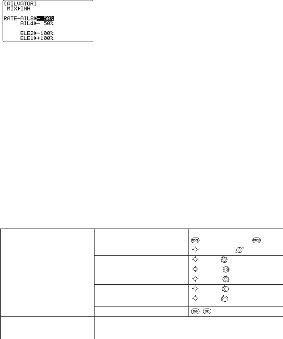
57
Dual Elevator Servos (with a rudder) (AILEVATOR) (ACRO): Many models use two elevator servos, plugged in separate
receiver channels. (Flying wings without a separate aileron control use ELEVON. V-shaped tail models use V-TAIL, p. 58.
%HQH¿WV
• Ability to adjust each servo's center and end points for perfectly matched
travel.
• Ease of assembly, not requiring torque rods for a single servo to drive 2
surfaces.
(OHYDWRUVDFWLQJ DOVRDVDLOHURQVIRU H[WUHPHVWXQWÀ\LQJRU PRUHUHDOLVWLFMHW
À\LQJRSWLRQDO
• Redundancy, for example in case of a servo failure or mid-air collision.
Adjustability:
• CH2 and CH8 only. (With programmable mixing, could utilize CH5 as the 2nd elevator servo. See www.futaba-rc.com\
faq\ for examples.) THROTTLE-NEEDLE uses CH8 and cannot be active simultaneously.
• Direction of each servo's travel may be reversed in REVERSE or the set percentages may be reversed here.
• Elevator travels independently adjustable (both directions and percent).
• Optional action as ailerons (defaults to 50%UHVSRQVH7KLV UHVSRQVHFDQQRWEH DFWLYDWHGGHDFWLYDWHG LQ ÀLJKW 6HWWLQJ
AIL1 and 2 to 0GLVDEOHVWKLVIHDWXUH1RWHLI\RXZDQWWKLVEXWRQRIIZLWKDVZLWFKVHW AIL1 and 2 to 0 here, and use 2
mixes . AIL-to-ELEV and AIL-to-AUX2OLQNWULPRIIDVVLJQDVZLWFKWRJHWDLOHURQDFWLRQIURPWKHHOHYDWRUVHUYRVZKHQWKH
assigned switch is on. See p. 68.
)RUGHWDLOVRQVHWWLQJXSDFRPSOH[DHUREDWLFSODQHVXFKDVRQHZLWKZLQJVHUYRVIXOOVSDQDLOHURQVÀDSVAIRBRAKE/
crow etc, please visit www.futaba-rc.com\faq\. Many other setups are also available.)
The AILEVATOR mixing function uses one servo on each of the two elevators, and combines the elevator function with the
aileron function (unless aileron travel is set to 0). For aileron effect, the elevators are raised and lowered opposite of one
another in conjunction with the ailerons.
Once AILEVATORLVDFWLYDWHGXQOHVV\RX]HURRXWWKHDLOHURQ¿JXUHVVHHEHORZDQ\WLPH\RXPRYH\RXUDLOHURQVRUDQ\
programming moves your ailerons (ie. RUDDER-AILERON mixing), the radio automatically commands both elevator servos
to also operate as ailerons. To deactivate this action, simply set the 2 aileron travel settings to 0 in the AILEVATOR function.
This way the elevators will work only as elevators.
,IXVLQJWKHHOHYDWRUVDVDLOHURQVDVZHOOEHVXUHWRPRYHWKHHOHYDWRUDLOHURQVWLFNZKLOHFKHFNLQJWKHVHUYRPRWLRQV,ID
ODUJHWUDYHOLVVSHFL¿HGZKHQWKHVWLFNVDUHPRYHGDWWKHVDPHWLPHFRQWUROVPD\ELQGRUUXQRXWRIWUDYHO
GOAL of EXAMPLE: STEPS: INPUTS:
Activate twin elevator servos.Deactivate
the elevator-acting-as-ailerons portion
of this function.
Note: Depending upon your model's
geometry, you may need to reverse one
servo or set a negative percentage here.
Open the AILEVATOR function. for 1 second. (If BASIC, again.)
C
to AILEVATOR.
Activate the function.
C
to MIX. to ACT.
Optional: adjust up/down travel when
operating as ailerons. (Ex: 0.)
C
to AIL3. to 0%.
C
to AIL4. to 0%.
Optional: adjust total elevator travel
of each servo. (Ex: right servo elevator
travel to 98%, left to 96%.)
C
to ELE2. to 98%.
C
to ELE1. to 96%.
Close menu.
Where next? Adjust individual servo's SUB-TRIMs: see p. 49 and END POINTs: see p. 39.
Set up Twin Aileron Servos: see p. 51.
Set up AIRBRAKE mix: see p. 63.
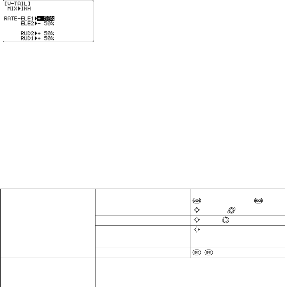
58
Using V-TAIL (ACROGLID):
V-TAIL mixing is used with v-tail aircraft so that both elevator and rudder
functions are combined for the two tail surfaces. Both elevator and rudder travel
can be adjusted independently on each surface.
NOTE: If V-TAIL is active, you cannot activate ELEVON or AILEVATOR functions. If one of these functions is active, an error
message will be displayed and you must deactivate the last function prior to activating ELEVON. see the wing example on
page 51.
NOTE: Be sure to move the elevator and rudder sticks regularly while checking the servo motions. If a large value of
WUDYHOLVVSHFL¿HGZKHQWKHVWLFNVDUHPRYHGDWWKHVDPHWLPHWKHFRQWUROVPD\ELQGRUUXQRXWRIWUDYHO'HFUHDVHWKH
travel until no binding occurs.
Adjustability:
• Requires use of CH2 and CH4.
• Independently adjustable travels allow for differences in servo travels.
• Rudder differential is not available. (To create rudder differential, set RUD1 and 2 to 0, then use two programmable mixes,
RUD-ELE and RUD-RUD, setting different percents for up and down. These are your new rudder travels. Trim and link off,
switch assignment null so you can’t accidentally turn off rudder. see PROG.MIX, p. 68.)
(For details on setting up a complex plane, such as one with a v-tail AND a separate steerable nosewheel, please visit our
FAQ at www.futaba-rc.com\faq\. Many other setup examples are also available at this location.)
GOAL of EXAMPLE: STEPS: INPUTS:
Activate V-TAIL.
Adjust left elevator servo to 95% travel
to match to right servo's travel.
Open the V-TAIL function. for 1 second. (If BASIC, again.)
C
to V-TAIL.
Activate the function.
C
to MIX. to ACT.
optional: adjust the travels separately
for the 2 servos as elevators. (Ex: set
left to 95%.)
C
to ELE1.to
95%.
Repeat as necessary for other servos.
Close menu.
Where next? Adjust END POINTs: see p. 32 and SUB-TRIMs: see p. 49.
6HWXSGXDOWULSOHUDWHVDQGH[SRQHQWLDOD/R,EXP): see p. 42.
Set up ELEV-FLAP mix: see p. 62.
View additional model setups on the internet: www.futaba-rc.com\faq\.
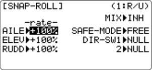
59
6QDS5ROOVDWWKHÀLFNRIDVZLWFKSNAP-ROLL) (ACRO):
7KLVIXQFWLRQDOORZV\RXWRH[HFXWHVQDSUROOVE\ÀLSSLQJDVZLWFKSURYLGLQJ
the same input every time. It also removes the need to change dual rates on the
3 channels prior to performing a snap, as SNAP-ROLL always takes the servos to
the same position, regardless of dual rates, inputs held during the snap, etc.
Note: Every aircraft snaps differently due to its C.G., control throws, moments, etc. Some models snap without aileron;
others snap on elevator alone. Most models snap most precisely with a combination of all 3 surfaces. Additionally, rate of
speed and acceleration when using the snap switch will affect how the model snaps. For information on using gyros with
airplanes for cleaner precision maneuvers, such as snaps and spins without over rotation, see p. 74.
Adjustability:
•Travel: Adjust the amount of elevator, aileron and rudder travel automatically applied.
•Range: -120 to +120 on all 3 channels. Default is 100% of range of all 3 channels.
•Directions:8SWRVHSDUDWHVQDSVPD\EHVHWXSRQHIRUHDFKRIWKHGLUHFWLRQFKRLFHVXSULJKWGRZQULJKWXSOHIW
GRZQOHIW(DFKVQDSLVIXOO\DGMXVWDEOHUHJDUGLQJWUDYHOVDQGGLUHFWLRQRQHDFKRIWKHFKDQQHOV
Note: for simplicity, the radio refers to snaps that use “UP” or positive elevator as “U” or “UP” snaps. This is more
commonly referred to as a positive or inside snap. “D” or “DOWN” snaps are more commonly referred to as negative or
outside snaps.
•R/U = Right positive R/D = Right negative L/U = Left positive L/D = Left negative snap roll
• Assignment of the 2 switches (DIR-SW1/2) to change snap directions is fully adjustable and optional. If you wish to have
only one snap, leave the switches as NULL. (If assigned, SW1 XSGRZQSW2 OHIWULJKW
• Caution: it is critical that you remember if you assigned switches to select the three additional snaps.
• For example, assign SWITCH A IRU 8' VQDS GLUHFWLRQ DQG WKHQ DOVR DVVLJQ SWITCH A for elevator dual rates.
:KLOHÀ\LQJRQHOHYDWRUORZUDWHSWITCH A DOWN) you pull your snap SWITCH. The model will:
•use the throws set in the snap programming (the low rate elevator has no effect); and
EHDGRZQQHJDWLYHRXWVLGHVQDSQRWDQXSSRVLWLYHLQVLGHVQDS
•Both of these may come as a great surprise and risk crashing if you are unprepared.
• Safety Switch (SAFE-MOD): a safety may be set up on your landing gear SWITCH, preventing accidental snap rolls while
the landing gear is down. The safety switch is turned on and off with the landing gear SWITCH.
•ON: the safety mechanism is activated when the landing gear SWITCH is in the same position as at the time this
feature is changed to ON. Snap rolls will not be commanded even if the snap roll SWITCH is turned on with the
gear SWITCH in this position. When the landing gear SWITCH is moved to the opposite position, snap rolls may
be commanded.
•OFF: activates the safety mechanism in the opposite position from the ON function.
•FREE: the safety mechanism is completely turned off. Snaps can be commanded regardless of the gear SWITCH
POSITION.
Note: The location of the safety switch always follows channel 5. If channel 5 is reassigned to switch C, for
example, switch C is now the safety. If channel 5 is nulled or used as the second aileron servo, the safety function
will not be available.
• Trainer Safety: SNAP-ROLL is automatically disabled when the trainer function is activated.
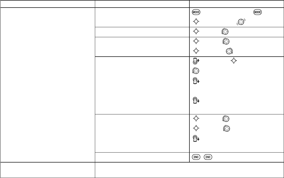
60
GOAL of EXAMPLE: STEPS: INPUTS:
Activate SNAP-ROLL. Adjust
elevatortravel to 55%, rudder travel to
120%LQWKHULJKWXSVQDS$FWLYDWH
SAFE-MOD so snaps can not be performed
when gear is down.
$GMXVWUXGGHUWUDYHOLQWKHOHIWGRZQ
snap to 105%.
(Note: using negative percents can
change any of the 4 snap directions. For
example, change snap 1 to "down" by
changing the elevator percent to -100%.)
Open the SNAP-ROLL function. for 1 second. (If BASIC, again.)
C
to SNAP-ROLL.
Activate the function.
C
to MIX. to OFF or ON.
Adjust the travels as needed. (Ex:
elevator to 55%, rudder to 120%.)
C
to ELEV. to 55%.
C
to RUDD. to 120%.
Optional: Activate SAFE-MOD. [Ex:
ON when SWITCH E (10CAG) or
G (10CHG) is down, meaning snap
function is deactivated when that switch
is in the down position.]
E or G up.
C
to SAFE-MODE
to ON.
snap switch.
Notice MIX reading is still OFF.
E or G down.
Notice MIX reading changes to ON.
Optional: Assign switches to up/down
and left/right. (Ex: Change to the left/
down snap and adjust rudder to 105%.)
C
to SW1. to A.
C
to SW2. to B.
A down B down.
Repeat steps above to set percentages.
Close menu.
Where next? Set up programmable mixes: see p. 61.
View additional setups on the internet:www.futaba-rc.com\faq\.
61
MIXES: the backbone of nearly every function
Mixes are special programs within the radio that command one or more channels to act together with input from only one
source, such as a stick, slider or knob.
There are a variety of types of mixes.
Types:
•Linear: Most mixes are linear. A 100% linear mix tells the slave servo to do exactly what the master servo is doing, using
100% of the slave channel’s range to do so. An example is FLAPERONZKHQDLOHURQVWLFNLVPRYHGWKHÀDSVHUYRLVWROG
to move exactly the same amount. A 50% linear mix would tell the slave servo, for example, to move to 50% of its range
when the master’s control is moved 100%. (see p. 52.)
•Offset: An OFFSETPL[LVDVSHFLDOW\SHRIOLQHDUPL[:KHQWKHPL[LVWXUQHGRQXVXDOO\DÀLSRIDVZLWFKWKHVODYH
servo is moved a set percent of its range. An example of this is AIRBRAKEPRYLQJÀDSVÀDSHURQVDQGHOHYDWRUDOOWRD
VHWSRVLWLRQDWWKHÀLSRIDVZLWFKVHHS
•Curve: Curve mixes are mostly used in helicopters, but may also be used in airplanes and gliders. An example is
THROTTLE-NEEDLE mixing, where the in-flight needle’s servo is moved, changing the mixture, as the throttle servo is
moved. (see p. 65.)
• Delay: Delay mixes are part of a few very special functions that make the servo move to its desired range more slowly.
THROTTLE DELAY (simulates turbine engines, p. 66) and the elevator delay in AIRBRAKE are two examples of this (see p. 62).
DELAY in HELI (see p. 103) is another example that slows the servo movement to the trim settings for the other conditions.
(VVHQWLDOO\HYHU\IHDWXUHLQWKHUDGLR¶VSURJUDPPLQJLVUHDOO\DPL[ZLWKDOODVVLJQPHQWVSURJUDPPLQJVHWXSDQGUHDG\
to use. Additionally, the 10CG ACRO and GLID programs both provide 4 linear and 4 curve fully-programmable mixes
(HELISURYLGHVOLQHDUDQGFXUYHWKDWDOORZ\RXWRVHWXSVSHFLDOPL[HVWRUHVROYHÀLJKWGLI¿FXOWLHVDFWLYDWHDGGLWLRQDO
functions, etc.
Let’s look quickly at a few examples that are features we’ve already covered. This may help to clarify the mix types and
the importance of mixes.
Additional examples:
• Exponential is a preprogrammed curve mix that makes the servos’ response more (+) or less (-) sensitive around center
stick (works in conjunction with dual rate, a linear mix that adjusts the total range). see D/R,EXP, p. 42.
•IDLE-DOWN and THR-CUT are two OFFSET pre-programmed mixes. These tell the throttle servo, when below a certain point,
to move toward idle an additional set percentage to help close the carburetor. see p. 40.
•ELEV-TO-FLAP PL[LQJ LV D SUHSURJUDPPHG OLQHDU PL[ WR PRYH WKH ÀDSV SURSRUWLRQDOO\ WR HOHYDWRU FRQWURO KHOSLQJ WKH
model loop even tighter than it can on elevator alone. (see p. 62.)
•THROTTLE-NEEDLE mixing is a curve mix (like PROG.MIX 5 to 8IRUSURSHULQÀLJKWQHHGOHVHWXSVHHS
•THROTTLE DELAY mixing is a pre-programmed delay mix that slows down the response of the CH3 servo. (see p. 66.)
Next, we'll get an in-depth look at some pre-programmed mixes (PL[HV ZKRVH FKDQQHOV DUH SUHGH¿QHG E\ )XWDED IRU
simplicity) we’ve not covered yet, and last, look at the fully-programmable mix types.
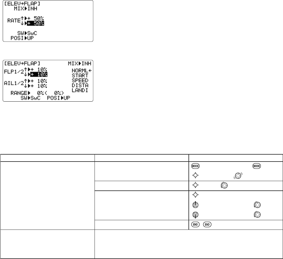
62
ELEV-FLAP mixing (ACROGLID):
ELEV-FLAPPL[LQJLVWKH¿UVWSUHSURJUDPPHGPL[ZHOOFRYHU7KLVPL[PDNHV
WKH ÀDSV GURS RU ULVH ZKHQHYHU WKH ELEVATOR STICK is moved. It is most
commonly used to make tighter pylon turns or squarer corners in maneuvers. In
PRVWFDVHVWKHÀDSVGURRSDUHORZHUHGZKHQXSHOHYDWRULVFRPPDQGHG
Adjustability:
•Rate IXOO XS ÀDS WR IXOO GRZQ ÀDS ZLWK D GHIDXOW RI
RQHKDOIRIWKHÀDSUDQJHLVDFKLHYHG when the ELEVATOR STICK is pulled
to provide full up elevator.)
•Switch: fully assignable. Also LOGIC SW (Lsw1 to 3) may be assigned. Set up
LOGIC SW: See p. 38.
*IF you set it to NULL, the mix does not work. (ACRO)
•Range (GLID): The range that mixing does not work near neutral of an elevator
stick can be set up.
Hold the stick to the desired point (upper or lower side) , then press DIAL and
hold one second to set the range.
•Condition (GLID): The separate ELEV-FLAP settings for each condition can be set.
(ACRO)
(GLID)
GOAL of EXAMPLE: STEPS: INPUTS:
Activate ELEV-FLAP mixing. Adjust flap
travel to 0%ÀDSVZLWKQHJDWLYHHOHYDWRU
(push) and 45% flaps with positive
elevator.
Open the ELEV-FLAP function. for 1 second. (If BASIC, again.)
C
to ELEV-FLAP.
Activate the function.
C
to MIX. to ACT.
Adjust the travels as needed.
(Ex: 0%,to 45%.)
C
to RATE.
ELEVATOR STICK. to 0%.
ELEVATOR STICK. to 45%.
Close menu.
Where next? $GMXVWÀDSHURQVÀDSWUDYHODYDLODEOHFLAPERON): see p. 52.
Set up AIRBRAKEFURZEXWWHUÀ\VHHS
Set up programmable mixes (ex: FLAP-ELEVATOR): see p. 68.
View additional setups on the internet: www.futaba-rc.com\faq\.
63
AIRBRAKEBUTTERFLY (crow) mixing (ACROGLID):
Like FLAPERON and AILEVATOR,AIRBRAKE is one function that is really made up of a series of pre-programmed mixes all
done for you within the radio. AIRBRAKE(often called "crow" or BUTTERFLY - see GLID, p. 80 for details) simultaneously
PRYHVWKHÀDSVLILQVWDOOHGWZLQDLOHURQVLILQVWDOOHGDQGHOHYDWRUVDQGLVXVXDOO\XVHGWRPDNHVWHHSGHVFHQWVRUWR
limit increases in airspeed in dives.
7KLVIXQFWLRQLVRIWHQXVHGHYHQRQPRGHOVZLWKRXWÀDSVDVDQHDV\ZD\WRXVHWKHÀDSHURQVDQGFLAP-ELEVATOR mixing
together.
Adjustability:
•Activation: Proportional by moving the THROTTLE STICKRUVHWSRVLWLRQVE\ÀLSSLQJWKHDVVLJQHGVZLWFK
•Switch: Mix SWITCH is selectable.
*Also LOGIC SW (Lsw1 to 3) may be assigned. Set up LOGIC SW: See p. 38.
•Linear(Inversely proportional to THROTTLE STICK): provides a proportional increase in amount of AIRBRAKE
action as THROTTLE STICK is lowered and assigned switch is on. Provides gradually more AIRBRAKE as you slow
the engine. Includes selectable stick position where AIRBRAKE begins, gradually increasing to the same setting as the
THROTTLE STICK is lowered. If you would like to have the airbrake be directly proportional to throttle stick, you will
need to reverse the THR-REV function. Note that this changes the throttle stick direction for all models. See page 38 for
instructions.
•Offset: Provides AIRBRAKE response immediately upon switch movement, going to a pre-set travel on each active channel
ZLWKRXWDQ\PHDQVRILQÀLJKWDGMXVWPHQW
• During Airbrake operation, the elevator travel is displayed on the elevator trim display in the Startup screen.
•Delayed reaction: You can suppress sudden changes in your model's attitude when AIRBRAKEBUTTERFLY is activated
by setting the delay (delay-ELEV LWHP WR VORZ GRZQ WKH HOHYDWRU UHVSRQVH DOORZLQJ WKH ÀDSVDLOHURQVHOHYDWRU WR DOO
reach their desired end point together. A setting of 100% slows the servo to take approximately one second to travel the
prescribed distance. (GLID:B.FLY-ELEV function)
•$GMXVWDEOHLQÀLJKWACRO): Using the aileron (when AILE-DIFF or FLAPERONLVDFWLYDWHGDQGHOHYDWRUWULPOHYHULQÀLJKW
can be set to adjust the aileron and elevator settings in your airbrake rather than adjusting the model's actual aileron and
HOHYDWRUWULP7KLVDOORZVHDV\DGMXVWPHQWIRUDQ\EDOORRQLQJZKLOHLQÀLJKW:KHQWKHDLUEUDNHVZLWFKLVPRYHGWRRII
the trims are again adjusting the normal elevator trim.
•Channels controlled(OHYDWRUVWZLQDLOHURQVDQGÀDSVPD\EHVHWLQGHSHQGHQWO\LQAIRBRAKE, including set to 0 to
have no effect.
• Twin aileron servos: If FLAPERON,ELEVON and AIL-DIFF functions are inhibited, then AIL1 and AIL2 settings will have no
effect.
•IfFLAPERON is active, the travel of the ailerons can be independently adjusted for the servos plugged into CH1 and
&+7KHÀDSFKRLFHKDVQRHIIHFWRQWKHÀDSHURQV
•IfAIL-DIFF is active, then CH1 and CH7 may be independently adjusted.
• Normally both ailerons are raised equally in AIRBRAKE, and the elevator motion is set to maintain trim when
the ailerons rise. Different amounts may be set for each aileron to correct for torque reactions and other unique
characteristics of the model.
Be sure you understand what dropping ailerons will do when in AIRBRAKEBUTTERFLY. Along with creating an
enormous amount of drag (desireble for spot landings), this also creates "wash-in", a higher angle of attack where
the ailerons are, and cncourages tip stalling. If you are using this for aerobatic performance and not "sudden stops",
FRQVLGHUUDLVLQJWKHDLOHURQVDQGGURSSLQJWKHÀDSVLQVWHDGDVVKRZQLQWKHGLDJUDPDERYH
(GLID)(ACRO)
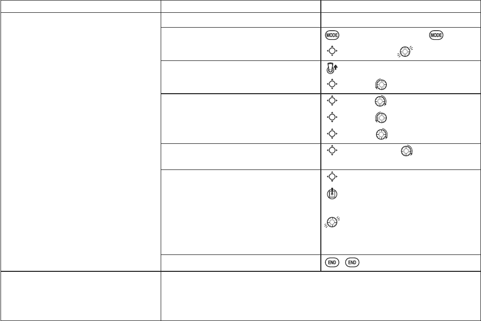
64
GOAL of EXAMPLE: STEPS: INPUTS:
Activate AIRBRAKE on a FLAPERON.
model. Adjust the flaperon travel to
75%,with negative elevator (push) of
25%.
&RQ¿UPFLAPERON is active. see FLAPERON instructions.
Open the AIRBRAKE function. for 1 second. (If BASIC, again.)
C
to AIRBRAKE.
Activate the function. Switch C in up position.
C
to MIX. to OFF.
Adjust the travels as needed.
(Ex:Ailerons each 75%, Elevator -25%.)
C
to AIL1. to 75%.
C
to ELEV. to -25%.
C
to AIL2. to 75%.
Optional: delay how quickly the
elevator servo responds.
C
to delay-ELEV. to 25%.
Optional: change the mixing from full
amount upon switch to proportional to
the THROTTLE STICK's proximity to
idle.
C
to MODE.to
Linear (0%).
THROTTLE STICK to desired 0
point.
for 1 sec, until beeps
(display changes if new setting is different from prior
setting).
Close menu.
Where next? $GMXVWÀDSHURQVWRWDOÀDSWUDYHODYDLODEOHFLAPERON): see p. 52.
Set up ELEV-FLAP mixing: see p. 62.
Set up programmable mixes, for example, FLAP-ELEVATOR: see p. 67.
View additional model setups on the internet: www.futaba-rc.com\faq\.
• Twin elevator servos:
•IfAILEVATOR is active, the AIL1 and AIL2 settings still only affect FLAPERON or AIL-DIFF servos, NOT the elevator servos.
(they would have the AIL3 and AIL4 settings.)
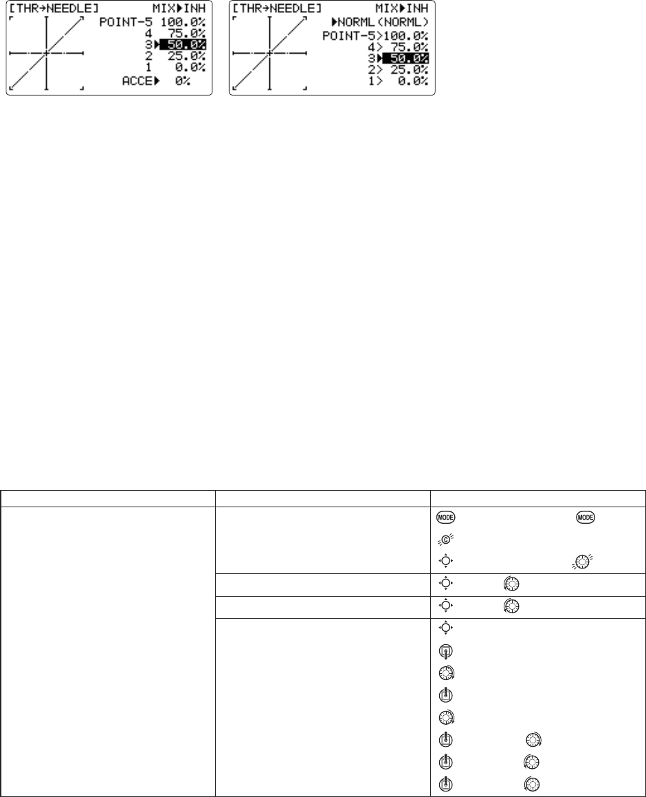
65
THROTTLE-NEEDLE mixing (ACROHELI):
THROTTLE-NEEDLELVDSUHSURJUDPPHGPL[WKDWDXWRPDWLFDOO\PRYHVDQLQÀLJKWPL[WXUHVHUYR&+LQUHVSRQVHWRWKH
THROTTLE STICK inputs for perfect engine tuning at all throttle settings. This function is particularly popular with
FRQWHVW SLORWV ZKR À\ LQ D ODUJH YDULHW\ RI ORFDWLRQV QHHGLQJ UHJXODU HQJLQH WXQLQJ DGMXVWPHQWV DQG UHTXLULQJ SHUIHFW
HQJLQHUHVSRQVHDWDOOWLPHVDQGLQDOOPDQHXYHUV$OVRSRSXODUWRPLQLPL]HÀRRGLQJDWLGOHRILQYHUWHGHQJLQHLQVWDOODWLRQV
or installations with a high tank position. Not needed for fuel injection engines, which do this automatically.
Adjustability:
• Five-point curve allows adjustment of engine mixture at varied throttle settings.
7KHLQÀLJKWPL[WXUHVHUYRPXVWFRQQHFWWRUHFHLYHU&+
,QÀLJKWPL[WXUHVHUYRPD\DOVREHXVHGDVDVHFRQGVHUYRIRUWXQLQJDWZLQ
7KURWWOHFXWIHDWXUHDOVRPRYHVWKHLQÀLJKWQHHGOHVHUYR
• The CH8 knob adjusts the high throttle mixture (may be deactivated. see AUX-CH).
• Because both use CH8, this function cannot be used simultaneously with AILEVATOR.
• An acceleration (ACCE) function (ACRO only) helps the engine compensate for sudden, large amounts of throttle input by
making the mixture suddenly richer, then easing it back to the proper adjustment for that throttle setting. This function
UHTXLUHVVRPHDGMXVWPHQWWREHVW¿W\RXUHQJLQHDQG\RXUÀ\LQJVW\OH$GMXVWHQJLQH¶VUHVSRQVHXQWLOQRKHVLWDWLRQRFFXUV
on rapid throttle input.
• Separate curves are available (HELI only) for normal, idle-ups 1 and 2 combined, and idle-up 3. Immediately below MIX
the radio displays the curve you are editing; ex: >NORML; and then which condition is currently active by your switches
ex: (ID1/2). Note that you can edit the mix for a different condition without being in that condition, to allow editing
without having to shut off the helicopter’s engine every time. Be sure you are editing the proper curve by checking the
name after the > and not the one in parentheses.
GOAL of EXAMPLE: STEPS: INPUTS:
Activate THROTTLE-NEEDLE mixing.
Adjust the points as follows to resolve
a slight lean midrange problem:
1: 40%
2: 45%
3: 65%
4: 55%
5: 40%
Open the THROTTLE-NEEDLE function. for 1 second. (If BASIC, again.)
to page 2.
C
to THROTTLE-NEEDLE.
Activate the function.
C
to MIX. to ACT.
HELI only. Select the condition to edit.
C
to MIX. to ACT. as needed.
Adjust the travels as needed to match
your engine by slowly moving the stick
to each of the 5 points, then adjusting
the percentage at that point until the
engine is properly tuned.
C
to POINT-.
THROTTLE STICK to POINT1.
to 40%.
until POINT 2 is highlighted.
to 45%.
to POINT 3. to 65%.
to POINT 4. to 55%.
to POINT 5. to 40%
(HELI)(ACRO)
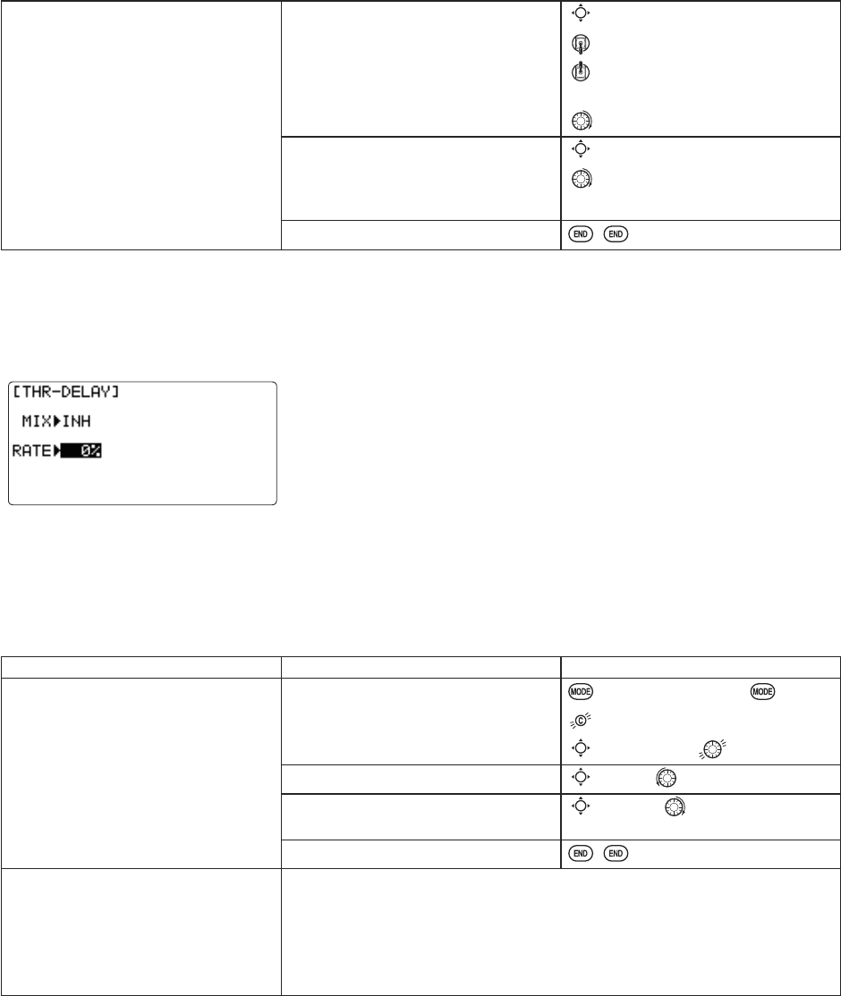
66
Throttle delay function THR-DELAY (ACRO):
The THR-DELAY function is used to slow the response of the throttle servo to
simulate the slow response of a turbine engine. A 40% delay setting corresponds
to about a one-second delay, while a 100% delay takes about eight seconds to
respond. For helicopters, see DELAYS, p. 103.
This function may also be used to create a “slowed servo” on a channel other than throttle. This is accomplished by
plugging the desired servo (Ex: gear doors) into CH3 (THR), throttle into an auxiliary channel such as 8, and then using
VRPHFUHDWLYHPL[HV3OHDVHVHHRXU)UHTXHQWO\$VNHG4XHVWLRQVDUHDDWZZZIXWDEDUFFRP?IDT?IRUWKLVVSHFL¿FH[DPSOH
GOAL of EXAMPLE: STEPS: INPUTS:
Activate THR-DELAY for a ducted-fan
replica of a turbine-powered aircraft.
Slow the servo response byone second.
Open the THR-DELAY function. for 1 second. (If BASIC, again.)
to page 2.
C
to THR-DELAY.
Activate the function.
C
to MIX. to ACT.
Adjust the RATE to match the desired
servo speed. (Ex: 40%.)
C
to RATE. to 40%.
Close menu.
Where next? Set up THROTTLE-NEEDLE mixing: see p. 65.
Adjust throttle’s END POINT: see p. 39.
Adjust throttle exponential (D/R,EXP): see p. 42.
Set up AILEVATOR: see p. 57.
Set up programmable mixes, for example, RUDDER-AILERON: see p. 68.
View additional model setups on the internet: www.futaba-rc.com\faq\
ACRO only. Optional: increase mixture
when throttle is applied rapidly-
ACCE.(see above for details.)
C
to ACCE.
THROTTLE STICK to idle.
THROTTLE STICK full open
quickly.
as needed.
HELI only: set curves for other
conditions.
C
to condition name.
to next condition to edit.
Repeat above steps as needed.
Close menu.
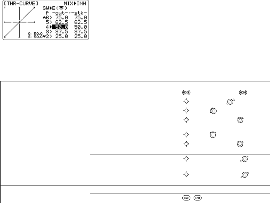
67
Throttle curve (THR-CURVE)(ACRO):
This function adjust the throttle operation curve for optimum the engine speed
to throttle stick movement.
NOTE: If the throttle EXP function is activated, you can not use THR-CURVE
function simultaneously.
Adjustability:
• Separate curves for each switch position are available.
•Moving and deleting the curve point: The curve point (-stk-) can be moved to the left or right by turning the DIAL (up to
LQIURQWRIWKHDGMRLQLQJSRLQWDQGGHOHWHGUHWXUQHGE\SUHVVLQJWKHDIAL for one second alternately.
GOAL of EXAMPLE: STEPS: INPUTS:
Base point: Adjust base point of throttle
curve until engine idles reliably.
-out-: output, servo position.
-stk-: curve point, stick position.
Open the THR-CURVE function. for 1 second. (If BASIC, again.)
C
to THR-CURVE.
Activate the function.
C
to MIX. to ON.
$GMXVWWKH¿UVWSRLQW
C
to point 1 (-out-). to desired
throttle servo position.
Optional: Assign the switch.
C
to SW. to desired switch.
Optional: Move the curve point.
(Ex: point 3)
C
to point 3 (-stk-). to desired
curve point to move to left or right.
Optional: Delete the curve point.
And return the curve point.
(Ex: point 3)
C
to point 3 (-stk-). for one
second to delete the curve point.
C
to point 3 (-stk-). for one
second to return.
Next point: Adjust the next point. Repeat as needed.
Close.
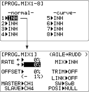
68
LINEAR PROGRAMMABLE MIXES (PROG.MIX1-4):
Sample reasons to use linear programmable mixes:
• To correct bad tendencies of the aircraft (such as rolling in response to rudder input).
• To operate 2 or more servos for a single axis (such as two rudder servos).
7RDXWRPDWLFDOO\FRUUHFWIRUDSDUWLFXODUDFWLRQVXFKDVORZHULQJHOHYDWRUZKHQÀDSVDUHORZHUHG
7RRSHUDWHDVHFRQGFKDQQHOLQUHVSRQVHWRPRYHPHQWLQD¿UVWFKDQQHOVXFKDVLQFUHDVLQJWKHDPRXQWRIVPRNHRLOLQ
response to more throttle application, but only when the smoke switch is active).
7RWXUQRIIUHVSRQVHRIDSULPDU\FRQWUROLQFHUWDLQFLUFXPVWDQFHVVXFKDVVLPXODWLQJRQHHQJLQHÀDPLQJRXWRQDWZLQ
or throttle-assisted rudder turns, also with a twin).
Adjustability:
• Defaults: The 4 programmable mixes default to the most frequently used mixes for simplicity. If you want to use one of
these mixes, simply select that mix number so that the master and slave servos are already selected for you.
•PROG.MIX1 aileron-to-rudder for coordinated turns
•PROG.MIX2HOHYDWRUWRÀDSIRUWLJKWHUORRSVHELI mixes default to elev-to-pitch.)
•PROG.MIX3ÀDSWRHOHYDWRUWRFRPSHQVDWHSLWFKLQJZLWKÀDSVHELI mixes default to pitch-to-elev.)
•PROG.MIX4 throttle-to-rudder ground handling compensation
•Channels available to mix: All four mixes may use any combination of CH1-8. (CH9-10 are not proportional and cannot
be mixed.) Offset and dials may also be set to the master channels. (see below.)
•Master: the controlling channel. The channel whose movement is followed by the slave channel.
•Another channel: Most mixes follow a control channel. (Ex: rudder-to-ailerons, 25%, no switch, corrects roll
coupling.)
MASTER SLAVE LINK TRIM SWITCH POSITION RATE OFFSET
RUDD AILE ON OFF ANY NULL 25% 0
•Offset as master: To create an OFFSETPL[VHW WKH PDVWHUDV2)67 ([PRYHÀDSHURQVDVÀDSV RI WKHLUWRWDO
throw when SWITCH C is in down position.)
MASTER SLAVE LINK TRIM SWITCH POSITION RATE OFFSET
OFST FLAP ON 1$ C DOWN 20% 0
•Dial as master: To directly effect one servo’s position by moving a dial, set the master as the desired dial.
(Ex: create a second throttle trim on left slider.)
MASTER SLAVE LINK TRIM SWITCH POSITION RATE OFFSET
VR(D) THRO OFF 1$ ANY NULL 5% 0
•Slave: the controlled channel. The channel that is moved automatically in response to the movement of the master
channel. The second channel in a mix’s name (i.e. aileron-to-rudder).
•Link: link this programmable mix with other mixes.
Ex: PMIX FLAP-ELEVATORPL[LQJWRFRUUHFWIRUEDOORRQLQJZKHQÀDSVDUHORZHUHGEXWPRGHOKDVD9WDLO:LWKRXWLINK,
Your 10CG contains four separate linear programmable mixes. (Note that mixer
#5-8’s mixing RATEs are set with a 5-point curve. HELI has mixer #5-6's mixing.
see CURVE MIXES, p. 71.)
There are a variety of reasons you might want to use these mixes. A few are
listed here. All of the adjustable parameters are listed below, but don’t let them
VFDUH\RX)RU\RXU¿UVWIHZ WLPHVH[SHULPHQWLQJZLWKPL[HV MXVWWXUQRQWKH
default mixes, adjust them how you think they need to be, then use the servo
screen to check and see if you were correct. As with all functions, a sample
setup follows, step by step, to assist you.
69
WKLVPL[RQO\PRYHV&+HOHYDWRUZKHQÀDSLVFRPPDQGHGUHVXOWLQJLQDGDQJHURXVFRPELQDWLRQRI\DZDQGUROO:LWK
LINK ON, mixing is applied to both CH2 and CH4.
MASTER SLAVE LINK TRIM SWITCH POSITION RATE OFFSET
FLAP ELEV ON OFF ANY NULL 5% 0
•Trim: master’s trim affects slave. Not displayed if master is not CH 1-4, because 5-9 have no trim. Ex: two rudder servos.
With TRIM OFF, rudder trim would bind the two servos. TRIM ON resolves this.
•On/off choices:
•SWITCH: Any of the positions of any of the 8 switches may be used to activate a mix. Up&Cntr,Cntr&Dn options
allow the mix to be ON in 2 of the 3 positions of a 3-position SWITCH.
•NULL: No SWITCH can turn this mix OFF. This mix is active at all times.
•LOGIC SW (Lsw1 to 3) may be assigned. Set up LOGIC SW: See p. 38.
•STk-THR7XUQHGRQRIIE\THROTTLE STICKPRYHPHQW7ULJJHUSRLQWGLUHFWLRQDUHVHOHFWDEOH([OFST-to-(gear
doors) mix to open gear doors at idle, which is only active if throttle is below half.
MASTER SLAVE LINK TRIM SWITCH POSITION RATE OFFSET
OFST AUX2 OFF NO STK-THR Stick at 1/2,
for 1 sec.
100% 0
•Rate: the percentage of the slave’s range it will move upon maximum input from the master channel. Ex: RUDDER-
AILERONPL[$LOUDQJH ´:KHQUXGGHULVPRYHGIXOOULJKWDLOHURQVPRYH´
MASTER SLAVE LINK TRIM SWITCH POSITION RATE OFFSET
RUDD AILE OFF OFF ANY NULL 50% 0
•Offset: Offsets the slave’s center relative to the master. Ex: Smoke valve opens wider per throttle servo position when
smoke SWITCH is ON. Smoke servo’s neutral is moved down from THROTTLE STICK center to the bottom.
MASTER SLAVE LINK TRIM SWITCH POSITION RATE OFFSET
THRO AUX2 OFF OFF E DOWN 100% 100%
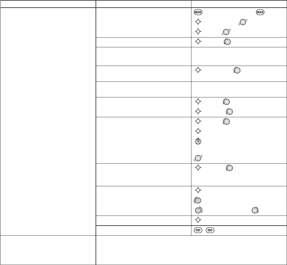
70
GOAL of EXAMPLE: STEPS: INPUTS:
Set up a FLAP-ELEV mix:
ON when SWITCH C is in the down
position.
1RHOHYDWRUPRYHPHQWZKHQÀDSVPRYH
up (spoilers),
5% elevator movement when flaps
move down,
LINK should be ON if model has twin
elevator servos. Otherwise, LINK
remains OFF.
(Flap has no trim lever, so TRIM is not
an option.)
Open an unused programmable mix.
(Ex: use PROG.MIX3 since it is already
set-up for FLAP-ELEVATOR.)
for 1 second. (If BASIC, again.)
C
to PROG.MIX-.
C
to 3 >.
Activate the function.
C
to MIX. to ON.
Choose master and slave channels.
(Ex: no need to change MASTER/SLAVE.)
already CH6
already CH2
Optional: set Master as OFST or VR(A-E).
See above for details.
C
to MASTER. to desired choice.
Set LINK and TRIM as needed.
(Ex: leave LINK OFF,TRIM not available.)
Assign SWITCH and position.
(Ex: change from E to C,DOWN.)
C
to SW. to C.
C
to POSI. to DOWN.
Optional: set switch to STk-THR to
activate mix with THROTTLE STICK.
(See above for details.)
C
to SW. to STk-THR.
C
to POSI.
THROTTLE STICK to desired
point.
for 1 second to set.
Optional: set switch position to NULL.
Makes mix active at all times. Not
compatible with STk-THR.
C
to POSI. to NULL.
Set rates. (Ex: Lo=0%, Hi=5%.)
C
to RATE.
VR(A) past center. Leave at 0%.
VR(A) past center. to 5%.
Set OFFSET, if needed. (Ex: 0.)
C
to OFFSET. Leave at 0%.
Close menu.
Where next? Adjust servo END POINTs: see p. 39.
6HWXSGXDOWULSOHUDWHVDQGH[SRQHQWLDOD/R,EXP): see p. 42.
Set up additional programmable mixes, ex: RUDDER-AILERON: see p. 68.
View numerous additional mix setups: www.futaba-rc.com\faq\
Other Examples:
•RUD-ELEV (ACROGLID) mix: Compensate for pitching up or down when rudder is applied.
•AIL-RUD mix (ACRO): Coordinate turns by applying rudder automatically with aileron input. All model types.
•ELEV-PIT (HELI) mix: compensate for the loss of lift of tilting the model.
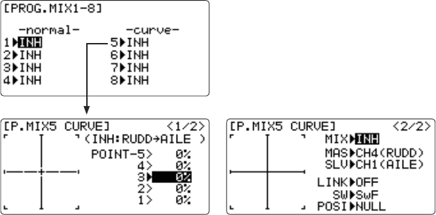
71
CURVE PROGRAMMABLE MIXES (PROG.MIX5-8)(HELI:PROG.MIX5-6 ):
Your 10CG’s ACROGLID programs contain four separate curve programmable mixes. HELI contains two. There are a variety
RIUHDVRQV\RXPLJKWZDQWFXUYHPL[HVXVXDOO\ZKHUHDOLQHDUPL[GRHVQ¶W¿W\RXUQHHGVDORQJWKHZKROHUDQJH2QHSUH
programmed curve mix is the THROTTLE-NEEDLE function. This curve is adjustable at 5 points, allowing you to adjust the
motor’s tuning at 5 points along its RPM range.
One programmable curve mix defaults to RUDDER-AILERON. A linear mix that keeps the model from rolling in knife-edge is
SUREDEO\WRRPXFKDLOHURQZKHQUXGGHULVDSSOLHGLQOHYHOÀLJKW&UHDWHDFXUYHPL[DQGVHWDOOSRLQWVWRPDWFKWKHOLQHDU
mix. Inhibit the linear mix, then adjust the curve to get the right response all along the rudder channel’s travel.
$GMXVWDELOLW\IRUGHWDLOHGGH¿QLWLRQVVHH/LQHDU3URJUDPPDEOH0L[HVDQG*ORVVDU\
•ACROGLID Defaults: The 4 programmable curve mixes default to the most frequent choices, but can be set to any channel.
•PROG.MIX5 rudder-to-aileron for roll coupling compensation (GLID mixes default to aileron-to-elev.)
•PROG.MIX6 rudder-to-aileron for roll coupling compensation (GLID mixes default to aileron-to-elev.)
•PROG.MIX7 rudder-to-elevator for pitch coupling compensation (GLID mixes default to elevator-to-airbrake.)
•PROG.MIX8 rudder-to-elevator for pitch coupling compensation (GLID mixes default to elevator-to-airbrake.)
•HELI Defaults:
•PROG.MIX5 aileron-to-elevator for coordinated turns
•PROG.MIX6 aileron-to-elevator for coordinated turns
•Master: The controlling channel can only be a channel. Cannot be OFFSET or dial.
•Trim: not available in curve mixes.
•Offset: not available in curve mixes.
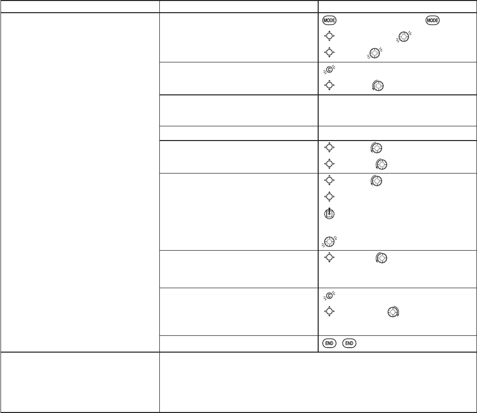
72
GOAL of EXAMPLE: STEPS: INPUTS:
Set up a RUDD-ELEV curve mix on a
model that pitches down severely at
full rudder and not at all with minimal
rudder input, and pitches worse on right
rudder than left:
Point 1: 25%
Point 2: 8%
Point 3: 0%
Point 4: 10%
Point 5: 28%
ON when SWITCH C is down.
LINK should be ON if model has twin
elevator servos. Otherwise, LINK
remains OFF.
(Note that point 3 is 0%. Otherwise,the
elevator would be retrimmed when the
mix is active and no rudder input is
given.)
Open an unused curve programmable
mix. (Ex: use PROG.MIX7 since it is
already set-up for RUDDER-ELEV.)
for 1 second. (If BASIC, again.)
C
to PROG.MIX-.
C
to 7 >.
Activate the function. to page 2.
C
to MIX. to ON.
Choose master and slave channels.
(Ex: do not change MAS or SLV).
already RUDD
already ELEV
Set LINK as needed. (Ex: off)
Assign SWITCH and position.
(Ex: change from F to C,DOWN.)
C
to SW. to C.
C
to POSI. to DOWN.
Optional: set switch to STk-THR to
activate mix with THROTTLE STICK.
(See above for details.)
C
to SW. to STk-THR.
C
to POSI.
THROTTLE STICK to desired
point.
for 1 second to set.
Optional: set switch position to NULL.
Makes mix active at all times. Not
compatible with STk-THR.
C
to POSI. to NULL.
Set desired percent at the stick points.
(Ex: listed at left.)
to page 1.
C
to POINT-1. to 25%.
Repeat for points 2-5.
Close menu.
Where next? Adjust servo END POINTs: see p. 39.
Set up AILEVATOR: see p. 57.
Set up linear programmable mixes, ex: RUDDER-to-Aux2(twin rudder servos):see p.
68, or additional curve mix, ex: RUDDER-AILERON: see p. 71.
View numerous mix setups: www.futaba-rc.com\faq\
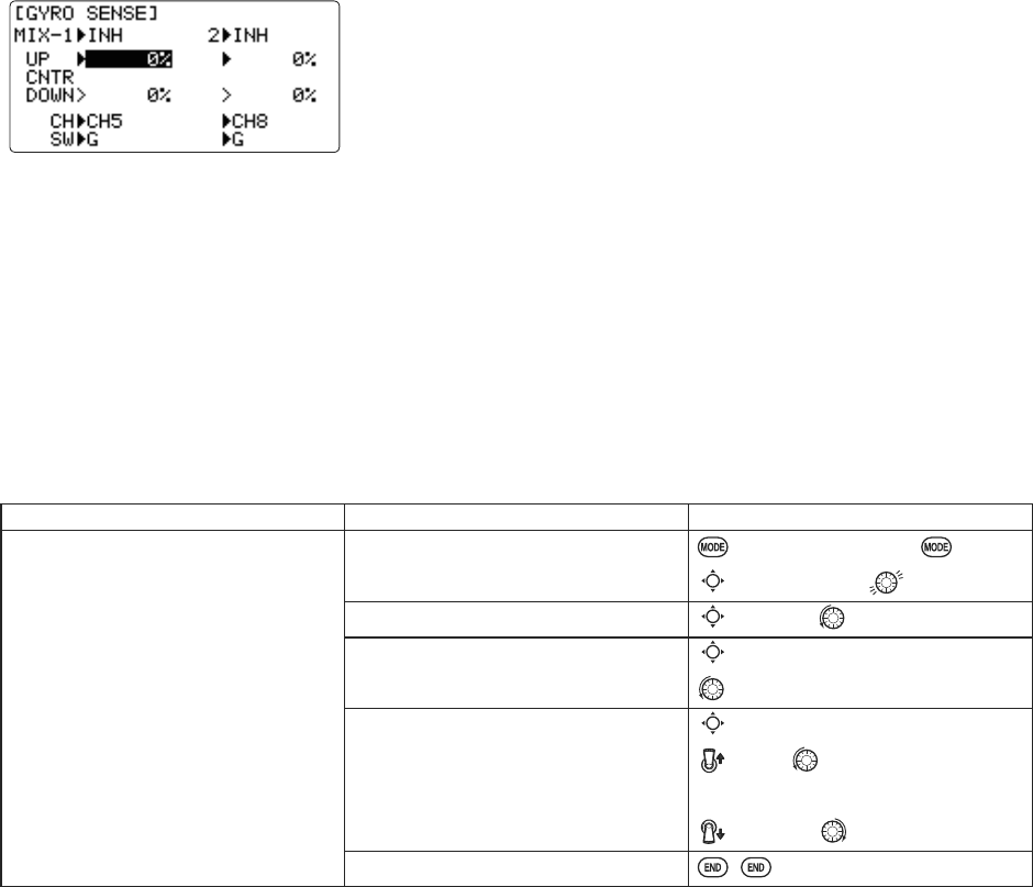
73
GYA gyro mixing
GYA series gyros:
GYA series gyros are a high performance, compact, and light weight AVCS gyro developed for model airplane. Integrated
sensor and control circuit make it easy to mount.
• GYA350: for airplane aileron, elevator, or rudder.
• GYA351: for airplane ailerons, especially two servos such as when using FLAPERON.
• GYA352: for airplane aileron, elevator, or rudder control. Two of these surfaces (axis) can be controlled by GYA352.
GYA series gyro operation modes:
The GYA gyros have two operations modes: AVCS mode and Normal mode.
• Normal mode: This mode performs general proportional control operation. For instance, it controls the gyro so that
changes are countered when the attitude of the aircraft is changed by cross-wind, etc.
• AVCS mode: This mode performs both proportional and integrated control operation. The difference between Normal
mode and AVCS mode operation is that where as the Normal mode only counters changes in attitude, the AVCS mode
returns to the original controlled variable simultaneously with countering changes in attitude. For example, during
NQLIHHGJHÀ\LQJDLOHURQDQGHOHYDWRUPHHWLQJUXGGHULVQRUPDOO\QHFHVVDU\EXWLQWKH$9&6PRGHPHHWLQJUXGGHULV
performed automatically by the gyro.
Adjustability:
• Plug the gyro's sensitivity adjustment to channel 5, 7, or 8 of the receiver.
(selectable)
• Full switch assignability (SWITCH A-H)
• Each rate setting may be set from 0 to NOR100% or AVC100% gain.
NOR: Normal mode gain. AVC: AVCS mode gain
• Larger percentages indicate more gain, or gyro responsiveness.
•MIX-1,2: Two surfaces' sensitivity can be adjusted independently.
Gyro gain adjustment:
• When the servo hunts, the gyro gain is too high. Lower the gain until the hunting stops.
7KH J\UR ZLOO GLVSOD\ EHVW SHUIRUPDQFH DW D JDLQ MXVW EHIRUH KXQWLQJ RFFXUV 3HUIRUP DGMXVWLQJ E\ À\LQJ WKH DLUFUDIW
repeatedly.
Precautions:
• When taking off and landing, always switch to the Normal mode. Taking off and landing in the AVCS mode is dangerous.
• We recommend that you use the rudder control gyro in the Normal mode. In the AVCS mode, rudder operation is
necessary when turning because the weathervane effect is lost. Use the gyro in the Normal mode unless you are an expert
in rudder operation.
• And we recommend that you also set to off (0%) mode for safety as follows.
GOAL of EXAMPLE: STEPS: INPUTS:
Set up a GYA gyro setting. (Ex: MIX-1) Open and activate the GYRO SENSE
function.
for 1 second. (If BASIC, again.)
C
to GYRO SENSE.
Activate the function.
C
to MIX-1. to ON.
Optional: change switch assignment.
Ex: select E.
C
to SW
to E.
Adjust gyro rates as needed. (Ex:UP
to NOR70%,CNTR to 0% (off),DOWN to
AVC70% as starting points.)
C
to gyro rate
E up. to NOR 70%.
(0%).
E down. to AVC 70%.
Close menu.

74
Special Additions, Functions, And Added Equipment Commonly Used On Powered Aircraft
Gyros: -XVWDVWRUTXHURWDWHVDQDLUFUDIWRQWKHUXQZD\GXULQJWDNHRIIKHOLFRSWHUV VWUXJJOH ZLWK WRUTXH WZLVWLQJ WKH
model every time throttle is applied. For many years gyroscopes have been used on model helicopters to control this. In
competition aerobatics and scale aircraft competition alike, the usefulness of gyros has recently come to light. For in-depth
information on gyro types, please see p. 106.
)RUDHUREDWLFVJ\URVRQUXGGHUDQGHOHYDWRU¿[RYHUURWDWLRQRIVQDSVDQGVSLQVDVZHOODVWDLOZDJJLQJLQVWDOOWXUQV)XWDED
offers a twin-axis gyro, GYA-352, that controls two axes with a single gyro.) For 3D aerobatics (below stall speed, such as
WRUTXHUROOVKHDGLQJKROG$9&6J\URVRQUXGGHUDQGHOHYDWRUGUDPDWLFDOO\VLPSOLI\WKHVHPDQHXYHUV)RUVFDOHPRGHOV
gyros are frequently used to simplify take-offs and landings by keeping the model straight during throttle application.
$OZD\V EH FDUHIXO LI XVLQJ D KHDGLQJKROG$9&6 J\UR DV LW ZLOO FRUUHFW DQ\ FKDQJH LQ \DZ WKDW LV QRW FDXVHG E\
PRYHPHQWRIWKHUXGGHUOLNHPDNLQJDWXUQ ZLWK MXVW DLOHURQ DQG HOHYDWRU7\SLFDOO\ PRGHOHUV XVH KHDGLQJKROG
$9&6VHWWLQJVRQO\IRUVSHFL¿FPDQHXYHUVVXFKDVWDNHRIIVDQGWRUTXHUROOVWKHQVZLWFKWRQRUPDOPRGHRU2))IRU
WKHUHPDLQGHURIWKHÀLJKWWRDYRLGWKLVULVN
Retracts: Retractable landing gear is often used on scale models for increased realism and on high performance models to
decrease drag. The gear servo is typically plugged into CH5, which defaults to a 2-position switch for simplicity.
Mechanical retracts require the use of a specialized non-proportional retract servo. Retract servos go from full travel
one direction to full travel the other direction, then mechanically hold the gear into the locked position. A regular
servo used for mechanical retracts will continue to draw full power the entire time, prematurely draining the battery
and risking crash of your model. End point will not adjust a retract servo.
Pneumatic (air driven) retracts use a standard servo to control an air valve which directs air into or out of the retract units,
moving the gear up or down. Pneumatics are easier to install but require added maintenance of the air system.
Gear Doors: Some scale models with retracts also have separate gear doors to cover the scale gear. For one example of
how to operate the gear doors separately from the retracts, please visit our website: www.futaba-rc.com\faq\.
Smoke Systems: Many scale and aerobatic models use smoke systems to provide increased realism or a more impressive
GHPRQVWUDWLRQ 7KHUH DUH PDQ\ VPRNH V\VWHPV DYDLODEOH ZLWK YDU\LQJ W\SHV RI FRQWURO 0RVW XVH D VHUYR WR LQFUHDVH
GHFUHDVHWKHÀRZRIVPRNHÀXLGLQWRWKHVSHFLDOL]HGVPRNHPXIÀHU7KHRLOLVKHDWHGLQWKHPXIÀHUFUHDWLQJVPRNH
It is a good practice to set up a "safety" that shuts off the smoke oil if the throttle is lowered below half-stick. For a detailed
example of a smoke system setup, please visit our website: www.futaba-rc.com\faq\.
Kill Switches: For safety reasons, it is strongly recommended that an electronic kill switch be installed in all gasoline-
SRZHUHGDLUFUDIW,QFDVHRIDQ\W\SHRILQÀLJKWSUREOHPVXFKDVSURSIDLOXUHH[KDXVWYLEUDWLQJRIIWKURWWOHVHUYRIDLOXUH
UDGLRLQWHUIHUHQFHWKHPRGHOHUFDQVKXWWKHHQJLQHRIITXLFNO\DQGVDIHO\LQÀLJKW$GGLWLRQDOO\)DLO6DIH)6VHWWLQJV
DUHUHFRPPHQGHGWRVKXWWKHHQJLQHRIILQFDVHRIVXI¿FLHQWLQWHUIHUHQFHWRWULJJHUWKH)DLO6DIHVHWWLQJV
Lastly, an electronic kill switch set to "off" prior to the aircraft's power being shut off adds an additional safety should
someone accidentally turn on the mechanical kill switch on the exterior of the model.
Bomb Drops, Paratroopers, and other Released Items: Many sport and scale models include one or more of these fun add-
ons. Typically, all are controlled by a simple micro-switch plugged into CH9 or CH10. The switch is assigned in AUX-CH.
75
GLIDER MODEL FUNCTIONS
Please note that nearly all of the BASIC menu functions are the same for airplane (ACRO setup), sailplane (GLID 1A+1F
2A+1F2A+2F setups), and helicopter (HELI setups). The features that are identical refer back to the ACRO chapter. The glider
BASIC menu includes MOTOR CUT and does not include IDLE-DOWN or THR-CUT.
Note that in all cases where ACRO programming labels channel 3 as throttle, GLID programming labels channel 3 as ARB
(airbrake), since airbrakes are normally operated on channel 3 in gliders. This includes STK-THR reading STK-ARB.
GLIDER (GLID(1A+1F)(2A+1F)(2A+2F)) FUNCTIONS . 75
Table of contents........................................................ 75
Getting Started with a Basic 4-CH Glider ................ 76
GLIDER BASIC MENU FUNCTIONS .......................... 78
MOTOR CUT ................................................................ 79
MODEL Submenu: MODEL SELECT,COPY,NAME .......... 30
PARAMETER Submenu: RESET, MODUL, ATL, AILE-2,
CONTRAST,BACK-LIGHT,USER NAME,LOGIC SW ........ 33
Model type (PARAMETER submenu) ........................... 78
Servo REVERSE ........................................................... 38
END POINT .................................................................. 39
'XDO7ULSOH5DWHVDQG([SRQHQWLDOD/R,EXP) .......... 42
TIMER Submenu.......................................................... 45
Auxiliary Channel assignments and CH9 reverse (AUX-
CH) ............................................................................. 46
TRAINER ..................................................................... 47
TRIM and SUB-TRIM ................................................... 48
SERVO Display ........................................................... 49
Fail Safe and Battery FailSafe (F/S) ......................... 50
GLIDER ADVANCE MENU FUNCTIONS ..................... 80
FLAPERON ................................................................... 52
FLAP TRIM .................................................................. 53
Aileron Differential (AILE-DIFF) ................................. 54
ELEVON (see tail types) ............................................... 56
ELEVON ....................................................................... 56
V-TAIL ......................................................................... 58
Linear, Prog. mixes 1-4 ............................................. 68
Curve, Prog. mixes 5-8 ............................................. 71
ELEV-FLAP .................................................................... 62
BUTTERFLY (modifyed version of AIRBRAKE) ............. 63
BUTTERFLY................................................................... 87
AILE/RUDD .................................................................. 81
AILE-FLAP (GLID(2A+2F) only) .................................... 82
SPOILER MIX ............................................................... 83
OFFSETs$GGLWLRQDOÀLJKWFRQGLWLRQV...................... 84
START DELAY (GLID(1A+1F) only) ................................. 85
CAMBER MIX ............................................................... 85
CAMBER FLAP .............................................................. 86
Channel 3’s function selection
(CONDITION/FUNCTION) 88
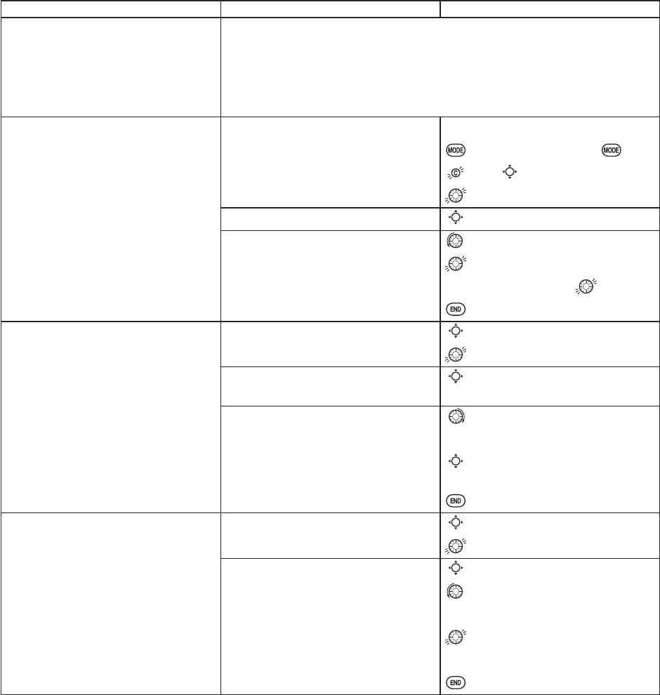
76
GETTING STARTED WITH A BASIC 4-CHANNEL (Aileron/Flap/Rudder/Elevator) GLIDER
This guideline is intended to help you get acquainted with the radio, to give you a jump start on using your new radio,
and to give you some ideas and direction in how to do even more with this powerful system than you may have already
considered. It follows our basic format of all programming pages: a big picture overview of what we’re trying to
accomplish; a “by name” description of the steps to help acquaint you with the radio; and a step-by-step instruction to
leave out the mystery and challenge of setting up your model.
For additional details on utilizing each function, see that function’s section in this manual—the page numbers are indicated
LQWKH¿UVWFROXPQDVDFRQYHQLHQFHWR\RX
GOAL of EXAMPLE: STEPS: INPUTS:
Prepare your aircraft. Install all servos, switches, receiver per your model’s instructions. Turn on
transmitter then receiver; adjust all linkages so surfaces are nearly centered.
Mechanically adjust all linkages to get as close as possible to proper control
throws and minimize binding prior to radio set up.
Check servo direction and throws.
Make notes now of what you will need to change during programming.
Select the proper MODEL TYPE for your
model. (Ex: GLID 1A+1F.) See p. 78.
[NOTE: This is one of several functions
that requires confirmation to make a
change. Only critical changes such as
aMODEL RESET require additional key
strokes to accept the change.]
In the BASIC menu, open the PARAMETER
submenu.
Turn on the transmitter.
for 1 second. (If ADVANCE, again.)
then
C
to highlight PARAMETER.
to choose PARAMETER.
Go to MODEL TYPE.
C
to MODEL TYPE.
Select proper MODEL TYPE.
Ex:GLID(1A+1F).
&RQ¿UPWKHFKDQJH
Close the PARAMETER submenu.
to GLID(1A+1F).
for 1 second.
Are you sure? Displays. WRFRQ¿UP
to return to BASIC menu.
NAME the model.
P. 32.
(Note that you do not need to do
anything to "save" or store this data.)
In the BASIC menu, open the MODEL
submenu.
C
as needed to highlight MODEL.
to choose MODEL.
Go to MODEL NAME.
C
to NAME.
(1st character of model’s name is highlighted.)
Input aircraft’s name.
Close the MODEL submenu when done.
WRFKDQJH¿UVWFKDUDFWHU
When proper character is displayed,
C
to move to next character and
repeat.
to return to BASIC menu.
REVERSE servos as needed for proper
control operation.
P. 38.
In the BASIC menu, open (servo)
REVERSE.
C
to REVERSE.
to choose REVERSE.
Choose desired servo and reverse its
direction of travel.
(Ex: reverserudder servo.)
C
to CH4:RUDD.
so REV is highlighted.
Are you sure? Displays.
for 1 second.
Repeat as needed.
to return to BASIC menu.
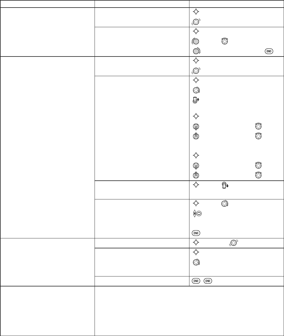
77
GOAL of EXAMPLE: STEPS: INPUTS:
Adjust travels as needed to match
model’s recommended throws (usually
listed as high rates).P. 39.
In the BASIC menu, choose END POINT.
C
to END POINT.
to choose END POINT.
Adjust the servos’ end points.
([ÀDSVHUYR
Close the function.
C
to FLAP.
VR(A) until travel as desired.
VR(A). Repeat as needed.
6HWXSGXDOWULSOHUDWHVDQGH[SRQHQWLDO
(D/R,EXP)
P. 42.
(Note that in the middle of the left
sideof the screen is the name of the
channel and the SWITCH position
you are adjusting. Two or even three
rates maybe set per channel by simply
choosing the desired SWITCH and
programming percentages with the
SWITCHLQHDFKRILWVSRVLWLRQV
Choose D/R,EXP.
C
to D/R,EXP.
to choose D/R,EXP.
Choose the desired control, and set
the first (Ex: high) rate throws and
exponential.
C
to CH>.
to choose CH>2 (elevator).
A to up position. [Note screen reads ELEV
(UP)]
C
to D/R.
ELEVATOR STICK. to set.
ELEVATOR STICK. to set.
(Normally the same for both directions.)
C
to EXP.
ELEVATOR STICK. to set.
ELEVATOR STICK. to set.
Set the second (low) rate throws and
exponential.
C
to D/R.A to down position.
Repeat above to set low rate.
Optional: change dual rate SWITCH
assignment. Ex: elevator to SWITCH G
with 3 positions.
C
to SW. to G.
G to center position.
Repeat steps above to set 3rd rate.
0RYHÀDSFRQWUROIURPWKH95$GLDO
to the left slider [VR(D)]. (AUX-CH)
p. 46.
In the BASICmenu, open AUX-CH.
C
to AUX-CH. to choose AUX-CH.
Choose CH6ÀDS
Change primary control to VR(D).
Change other channels as needed.
C
to CH6.
to VR(D).
Repeat as required.
Return to the home screen.
Where next? (Other functions you may wish to set up for your model.)
TRAINER p. 47.
Multiple wing or tail servos. See wing types and tail types: p. 51, 56.
OFFSETS,BUTTERFLY(AIRBRAKEFURZDQGRWKHUSURJUDPPDEOHPL[HVS
Retractable Gear, Smoke systems, kill switches, and other auxiliary channel
setups: p. 46.
Adjusting SUB-TRIMs to match servo centers: p. 49.
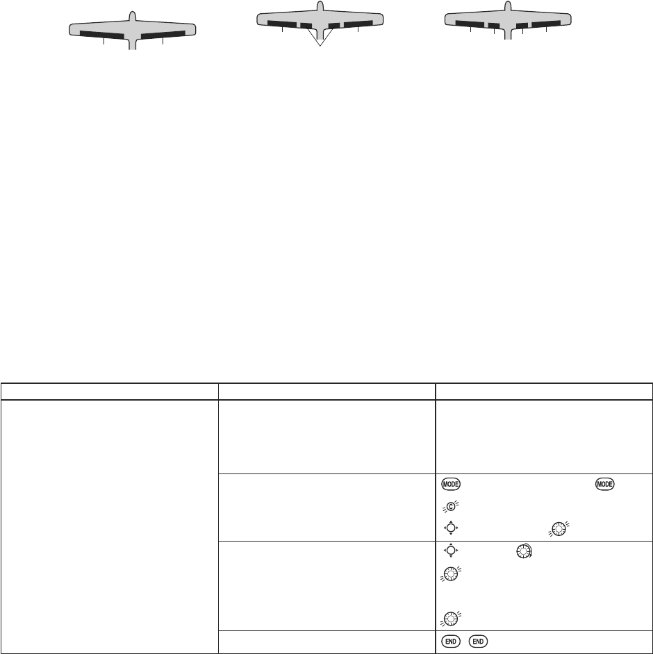
78
$/22.$77+(5$',26GLID-SPECIFIC FUNCTIONS STEP BY STEP.
Those functions which are identical to the ACRO setups are referred directly to those pages.
MODEL TYPE: This function of the PARAMETER submenu is used to select the type of model programming to be used.
GLIDER TYPES:
%HIRUHGRLQJDQ\WKLQJHOVHWRVHWXSDJOLGHURUVDLOSODQH¿UVW\RXPXVWGHFLGHZKLFKMODEL TYPEEHVW¿WV\RXUDLUFUDIW
•ACROIRUVRPHDHUREDWLFVORSHJOLGHUVACRO is a better choice because of functions it offers that the GLID types do not.
•ACRO provides:
•SNAP-ROLL,
•AILEVATOR (twin elevator servo support),
•AIRBRAKE (a more assignable version of BUTTERFLY).
• For nitro-powered sailplanes: IDLE-DOWN,THR-CUT,THROTTLE-NEEDLE mixing and THROTTLE DELAY programming.
• But ACRO ODFNV SURJUDPPLQJ IRU IXOOVSDQ DLOHURQV DQG VHSDUDWH 2))6(7 WULPV IRU HDFK ÀLJKW FRQGLWLRQ 1RUPDO
Start, Speed, Distance and Landing.
•GLID(1A+1F): The GLID(1A+1F) MODEL TYPE is intended for sailplanes with one or two aileron servos (or none), and a single
ÀDSVHUYRRU WZR FRQQHFWHG ZLWK D\FRQQHFWRU7KLV TYPE is meant to be a very simplistic version to set up a basic
JOLGHUZLWKRXWDORWRIDGGHGIHDWXUHV$GGLWLRQDOÀLJKWFRQGLWLRQVDYDLODEOH
•GLID(2A+1F): The GLID(2A+1F) MODEL TYPELVLQWHQGHGIRUVDLOSODQHVZLWKGXDODLOHURQVHUYRVDQGDVLQJOHÀDSVHUYRRU
WZRFRQQHFWHGZLWKD\FRQQHFWRU$GGLWLRQDOÀLJKWFRQGLWLRQVDYDLODEOH7KHVHÀLJKWFRQGLWLRQVFRQWDLQGLIIHUHQWRIIVHW
trims and aileron differentials to make the sailplane perform certain maneuvers more easily.
•GLID(2A+2F): The GLID(2A+2F) MODEL TYPE supports dual flap servos that can also act as ailerons, creating full-span
DLOHURQVDQGÀDSV$GGLWLRQDOÀLJKWFRQGLWLRQVDYDLODEOH7KHVHÀLJKWFRQGLWLRQVFRQWDLQGLIIHUHQWRIIVHWWULPVDQGDLOHURQ
differentials to make the sailplane perform certain maneuvers more easily.
GOAL of EXAMPLE: STEPS: INPUTS:
Change model1 is MODEL TYPE to
GLID(1A+1F).
NOTE: This is one of the several
functions that the radio requires
FRQ¿UPDWLRQWRPDNHDFKDQJH
Confirm you are currently using the
proper model memory. (Ex: 1)
On home screen, check model nameand
number on top left.
If it is not the correct model (Ex: 1), use
MODEL SELECT, p. 25.
Open PARAMETER submenu. for 1 second. (If ADVANCE, again.)
to 2nd page of menu.
C
to PARAMETER.
Change the MODEL TYPE.
&RQ¿UPWKHFKDQJH
C
to TYPE. to GLID(1A+1F).
for one second.
Are you sure?&RQ¿UPDWLRQGLVSOD\V
WRFRQ¿UP
Close.
GLID(1A+1F)
(FLAPERON)
AIL1
FLP2
(CH1)
AIL2
FLP1
(CH6)
AIL1
(CH1)
AIL2
(CH7) FLP
(CH6)
GLID(2A+1F)
AIL1
(CH1)
FLP1
(CH6)
FLP2
(CH5)
AIL2
(CH7)
GLID(2A+2F)
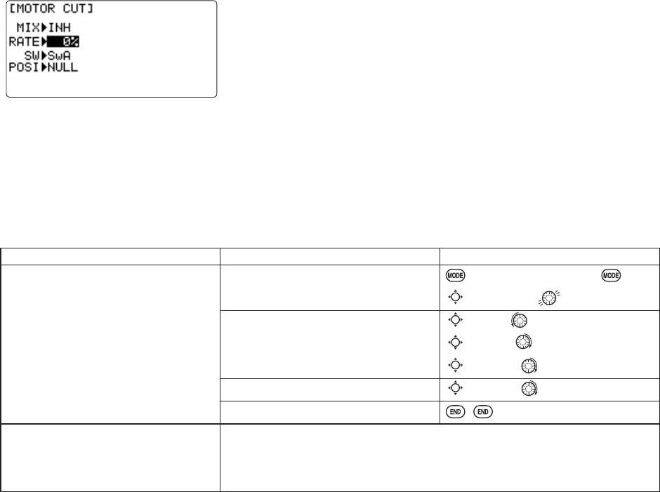
79
Motor cut function (MOTOR CUT) (GLID SURYLGHV DQ HDV\ ZD\ WR VWRSWKHPRWRUE\ÀLSSLQJDVZLWFK UHJDUGOHVV RI WKH
AIRBRAKE STICK position. The servo movement is largest at -30%.
The switch's location and direction must be chosen. It defaults to NULL to avoid
accidentally assigning it to a switch, which might result in an unintentional dead
VWLFNLQÀLJKW
Adjustability:
•RATE range of -30 to +30. The servo movement at 0% is maximum slow position of AIRBRAKE STICK. The servo
movement is largest at -30%.
•SWITCH A-H fully assignable. Also LOGIC SW (Lsw1 to 3) may be assigned.
•POSITION fully assignable, including NULL (mix always off) and Up&Cntr and Cntr&Dn to activate the mix in 2 separate
positions of the same SWITCH.
GOAL of EXAMPLE: STEPS: INPUTS:
Decrease the rate to stop the motor
ZLWKWKHÀLSRIDVZLWFK1RWHWKDW\RX
MUST assign a switch. The default is
NULL.)
Open BASICmenu, then open THR-CUT
function.
for 1 second. (If ADVANCE, again.)
C
to THR-CUT.
Activate the function. Choose desired
switch, and the position which activates
the function.
C
to MIX. to OFF or ON.
C
to SW. to desired switch.
C
to POSI. to desired position.
C
to RATE. until turns off.
Close.
Where next? 6HWXSGXDOWULSOHUDWHVDQGH[SRQHQWLDOD/R,EXP): see p. 42.
Set up TRAINER functions: see p. 47.
Set up twin aileron servos: see p. 51.
Set up twin elevator servos: see p. 57.
*Also LOGIC SW(Lsw1 to 3) may be assigned. Set up LOGIC SW: See p. 38.
80
GLIDER ADVANCE MENU
Varied wing types and tail types (twin aileron servos, twin elevator servos, elevon, v-tail, etc). See p. 51-58 for basic
information.
•FLAPERON (GLID 1A+1FRQO\DLOHURQVHUYRVRSHUDWHLQRSSRVLWHGLUHFWLRQVDVDLOHURQVDQGVDPHGLUHFWLRQDVÀDSV6HH
p. 45.
•CAMBER FLAPSURYLGHVFDPEHUPRYHPHQWRUWULPPLQJRIÀDSV6HHS
• For sailplanes, this function is also used as wing camber. The amount depends on the model, but usually a small
amount (less than 10%) is preferred, since too much camber produces excess drag. Don’t use more than about
´ WUDYHO XS RU GRZQ IRU JOLGHU FDPEHU 6RPH DLUIRLOV VXFK DV WKH 5* VKRXOG EH ÀRZQ ZLWK 12 UHÀH[
camber. Be sure to consult your model’s manual for guidelines.
• Note that even though you may make CAMBER FLAP active while using AILE-DIFF, it will not have any effect. The
21/<IXQFWLRQWKDWDOORZVFRQWURORIWKHDLOHURQVDVÀDSVLQWKHAILE-DIFFFRQ¿JXUDWLRQLVDLUEUDNHEXWWHUÀ\
•Aileron Differential (AILE-DIFF): allows twin aileron servos to provide differential down travel from up travel. See p.
54.
•Using Twin Aileron Servos with FLAPERON and AILE-DIFF. See AIL-2, p. 55.
•ELEVONIRUÀ\LQJZLQJV6HHS
•V-TAIL: for models with 2 servos operating together to create roll and pitch control. See p. 58.
•AILEVATOR: not available in GLID model types.
Mixes:
•Linear Programmable mixes (PROG.MIX1-4): fully assignable programmable mixes with a linear response. see p. 68.
•Curved Programmable mixes (PROG.MIX5-8): fully assignable programmable mixes with a curved response. See p.
71.
•ELEV-FLAPSUHSURJUDPPHGPL[FUHDWHVHOHYDWRUPRYHPHQWIURPWKHLQERDUGÀDSVDVZHOODVHOHYDWRUV6HHS
•BUTTERFLY: Often called crow, BUTTERFLY is the glider version of AIRBRAKE. (BUTTERFLY does not have the option to
activate it solely from a switch, and its activation switch. It always provides progressively more BUTTERFLY as the
CHANNEL 3 (THROTTLE)STICK is lowered, or raised if used THR-REV, p.38.) See AIRBRAKE, p. 63.
Full Span Mixing: Flap-to-Aileron and Aileron-to-Flap
•CAMBER-MIXAILE-FLAP7KLV SUHSURJUDPPHG PL[ LV XVHG WR FUHDWH IXOO VSDQ ÀDSDLOHURQ DFWLRQ RQ D JOLGHU ZLWK
ZLQJVHUYRV7KLVFKDQJHVWKHFDPEHURYHUWKHHQWLUHZLQJZKLFKSURGXFHVOHVVGUDJWKDQMXVWGURSSLQJWKHÀDSVE\
themselves.
NOTE: When you have ELEV-FLAP mixing also, the trailing edge droops with the elevators, increasing pitch response.
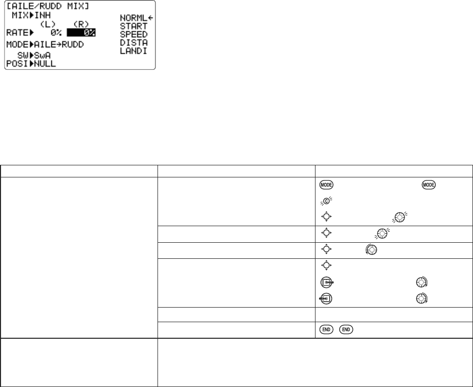
81
AILERUDD(GLID):
Adjustability:
•RATE range of -100 to +100. Negative setting would result in opposite rudder (aileron) action from aileron (rudder).
•SWITCH A-H fully assignable. Also LOGIC SW (Lsw1 to 3) may be assigned. Set up LOGIC SW: See p. 38.
•POSITION fully assignable, including NULL (mix always on) and Up&Cntr and Cntr&Dn to activate the mix in 2 separate
positions of the same SWITCH.
•Condition: The separate AILERUDDVHWWLQJVIRUHDFKÀLJKWFRQGLWLRQFDQEHVHW
GOAL of EXAMPLE: STEPS: INPUTS:
([58''ĺ$,/(QRVZLWFK
corrects roll coupling.
Open AILERUDD mix submenu. for 1 second. (If BASIC, again.)
to 2nd page of menu.
C
to AILERUDD.
Select the mixing mode.
C
to MODE. to RUDDĺAILE
Activate the function.
C
to MIX to ON.
Set the rate. (Ex: 100% each way)
C
to FLP1.
RUDDER STICK. to +25%.
RUDDER STICK. to +25%.
Repeat as needed.
Close.
Where next? ELEV-FLAP mixing. See p. 62.
BUTTERFLY. See p. 63.
Use a mix to OFFSETWKHÀDSVDVHWGLVWDQFHRQDVSHFL¿HGVZLWFKVHHS
View additional model setups on the internet: www.futaba-rc.com\faq\
You can select a pre-programed mix which is used to mix the rudders with
aileron operation or the ailerons with rudder operation.
Aileron-to-rudder mix (AILEĺRUDD): automatically creates a "coordinated turn".
Rudder -to-aileron mix (RUDDĺAILE): used to counterract undesirable roll (roll
coupling) that happens with rudder input, especially in knife-edge.
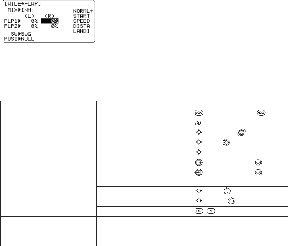
82
AILE-FLAP(GLID 2A+2F only):
Adjustability:
•RATEUDQJHRIWR1HJDWLYHVHWWLQJZRXOGUHVXOWLQRSSRVLWHDLOHURQDFWLRQIURPÀDSV
•SWITCH A-H fully assignable. Also LOGIC SW (Lsw1 to 3) may be assigned. Set up LOGIC SW: See p. 38.
•POSITION fully assignable, including NULL (mix always on) and Up&Cntr and Cntr&Dn to activate the mix in 2 separate
positions of the same SWITCH.
•Condition: The separate AILE-FLAPVHWWLQJVIRUHDFKÀLJKWFRQGLWLRQFDQEHVHW
GOAL of EXAMPLE: STEPS: INPUTS:
Turn on AILE-FLAP mixing. Set rate
to100% for maximum possible flap
travel with ailerons. Assign to SWITCH
C center.
Open AILE-FLAP submenu. for 1 second. (If BASIC, again.)
to 2nd page of menu.
C
to AILE-FLAP.
Activate the function.
C
to MIX to ON.
Set the rate. (Ex: 100% each way)
C
to FLP1.
AILERON STICK. to +100%.
AILERON STICK. to +100%.
Repeat above to set FLP2.
Assign the SWITCH and position.
C
to SW. to C.
C
to POSI. to CENTER.
Close.
Where next? ELEV-FLAP mixing. See p. 62.
BUTTERFLY. See p. 63.
Use a mix to OFFSETWKHÀDSVDVHWGLVWDQFHRQDVSHFL¿HGVZLWFKVHHS
View additional model setups on the internet: www.futaba-rc.com\faq\
This pre-programmed mix is used to create full span aileron action on a glider
with 4wing servos. This increases the roll rate and decreases induced drag.
)RUQRUPDOÀ\LQJDYDOXHRIDERXWLVRIWHQXVHG)RUVORSHUDFLQJRU)%
models in speed runs, you may wish to use a larger value approaching 100%.
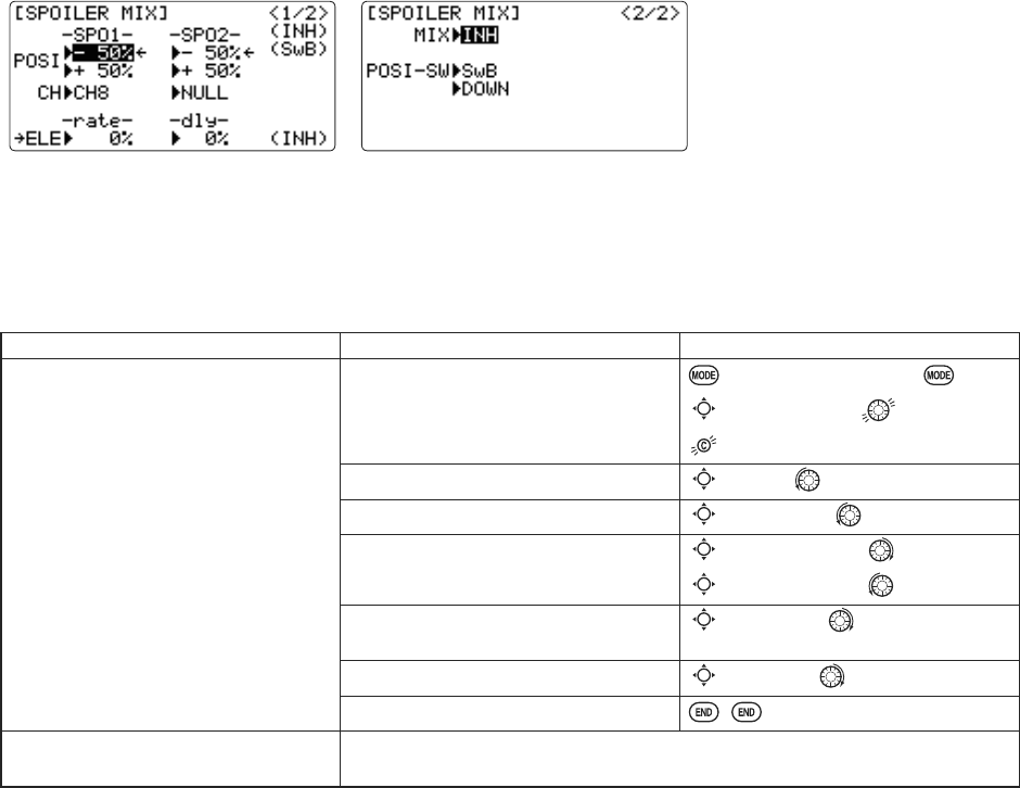
83
SPOILER MIX (GLIDPRYHVWKHVSRLOHUVE\ÀLSSLQJWKHDVVLJQHGVZLWFKDQGLVXVHGWRPDNHVWHHSGHVFHQWV$QGSPOILER
MIX works linking with BUTTERFLY function.
Adjustability:
•Position: -100% to +100%, with a default of -50% (off), +50% (on)
•Channel: Spoiler 1: ch8, 5 or 3 (ch8 or 3*), Spoiler 2: NULL, ch5 or 3 (NULL or ch3*) *GLID (2A+2F) mode
•Elevator setting: Rate: -100% to +100%, Delay: 0% to 100%
•SWITCH A-H fully assignable. Also LOGIC SW (Lsw1 to 3) may be assigned. Set up LOGIC SW: See p. 38.
GOAL of EXAMPLE: STEPS: INPUTS:
2-servo spoiler mode.
Adjust the spoiler servo position to
60%.
Open the SPOILER MIX function and
move to 2nd page.
for 1 second. (If BASIC,again.)
C
to SPOILER MIX.
to 2nd page.
Activate the function.
C
to MIX. to ON.
Assign the SPO2-CH. (Ex: CH3)
C
to SPO2-CH. to CH3.
Adjust the spoiler servo position.
(Ex: SPO1SPO2=+55% to +60%)
C
to +50%. (SPO1) to +60%.
C
to +50%. (SPO2) to +60%.
Optional: Set the elevator rate.
(EX: 10%)
C
to rate-ELE. to 10%.
Optional: Set the delay. (EX: 25%)
C
to dly-ELE. to 25%.
Close menu.
Where next? Set up BUTTERFLY mixing: see p. 87.
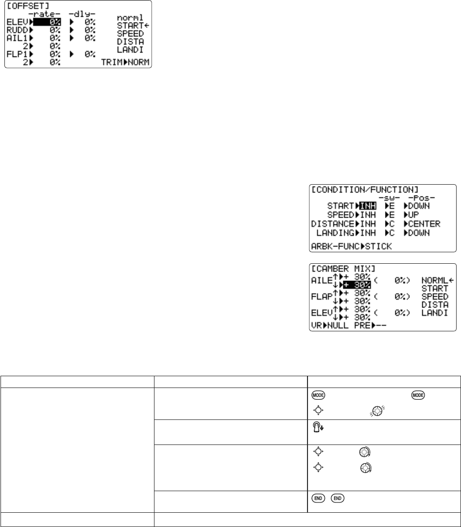
84
OFFSETsDGGLWLRQDOÀLJKWFRQGLWLRQVDYDLODEOHVSHFL¿FDOO\IRUVDLOSODQHV
Unnecessary fusulage motion is generated when there are sudden changes in the servo position and variations in the
operating time between channels can be suppressed by using the delay function (-dly-).
NOTE: The same delay amount for elevator and rudder is recommended when using V-tail function.
7KH&*SURYLGHVRIIVHWWULPVWRDOORZWKHPRGHOHUDGGLWLRQDOVHWXSVDORQJZLWKWKHQRUPDOÀLJKWFRQGLWLRQNORMAL,
START,SPEED,DISTANCE and LANDING) These offset trims have same setting abilities basically except the switch and dial
assignment. For an example of trim settings, please see the following:
Adjustability:
6HSDUDWHDGMXVWPHQWVIRUHDFKDLOHURQHOHYDWRUUXGGHUDQGÀDSVHUYRIRUHDFK
condition.
•SWITCH G (10CAG) or E (10CHG) is programmed for NORMAL,START, and
SPEED trims. SWITCH C is programmed for DISTANCE and LANDING trims.
7KHVHVZLWFKSRVLWLRQDVVLJQPHQWLVDGMXVWDEOHCONDITION/FUNCTION)
•TRIM item (Digital trim operation mode):
NORM: normal trim operation mode,
MIX: offset rate trim operation mode while mixing is on.
• Optional assignable knob (CAMBER MIX) to allow trimming in flight of the
DLOHURQDQGÀDSDFWLRQRIHDFKÀLJKWFRQGLWLRQ
*During OFFSET operation, the aileron and elevator travels are displayed on each
trim display in the Startup screen.
GOAL of EXAMPLE: STEPS: INPUTS:
Set up a START to gain maximum
possible lift on launch.
Each Aileron: 50%.
Each Flap: 100%.
Elevator: -5% to compensate.
SWITCH (10CAG=G, 10CHG=E.)
Note: switch is assignable. (CONDITION)
KNOB(null)
Note: knob is assignable. (CAMBER MIX)
Open OFFSET function. for 1 second. (If BASIC, again.)
C
to OFFSET.
Switch to the START condition. G (10CA) or E (10CH) from
NORMAL to START.
Set the rates. (Ex: AIL1 and 2,50%,FLP1
and 2,100%,ELEV -5%.)
C
to AIL1. to +50%.
C
to AIL2. to +50%.
Repeat for, FLP1 and 2,ELEV.
Close the function.
Where next? View additional model setups on the internet: www.futaba-rc.com\faq\
These additional flight conditions contain different offset trims to make the
saiplane perform certain maneuvers more easily. Aileron differential functions
may be set to provide separate rates per condition selected.
Prior to setting up OFFSET, you must active the conditions and assign the
switches in the CONDITION/FUNCTION.
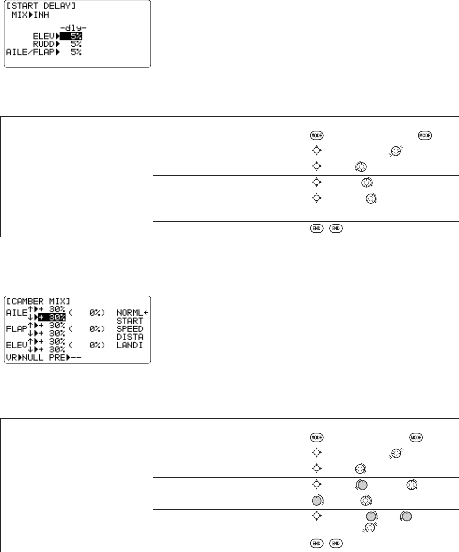
85
Camber Mixing (CAMBER MIX)(GLID):
This function adjusts the mixing rate of camber operation which operates the
ZLQJ FDPEHU DLOHURQV DQG ÀDSV LQ WKH QHJDWLYH DQG SRVLWLYH GLUHFWLRQV7KH
DLOHURQÀDSDQGHOHYDWRUUDWHVFDQDOVREHDGMXVWHGLQGHSHQGHQWO\DQGDWWLWXGH
changes caused by camber operation can be corrected.
Also the operation reference point of camber control can be offset. (PRE)
NOTE: Camber control is not assigned at initial.
GOAL of EXAMPLE: STEPS: INPUTS:
Ex: Set the mixing amount for aileron
to 40%, camber control to VR(E),
reference point to desired point.
Open the CAMBER MIX function. for 1 second. (If BASIC, again.)
C
to CAMBER MIX.
Choose desired slider.
C
to VR. to VR(E).
Adjust the mixing amount for AILE.
(Ex: adjust to 40%.)
C
to AILE.VR(E). to 40%.
VR(E). to 40%.
Set the reference point.
C
to PRE. or VR(E) to
desired point. for one second.
Close menu.
Adjustability:
•Rate: -100% to +100%, with a default of +30%
•
Reference point (PRE): The operation reference point of camber control can be offset. -100% to +100%, with a default of 0%.
START DELAY (GLID 1A+1F only):
START DELAY automatically switch the offset trims (OFFSET) from the START
condition's trims to the normal cndition's trims after proceeding the delay time
(max.10sec.) which is set by the -dly- item when activating the START condition.
(It is convenient for hand launch glider.)
NOTE: The same delay amount for elevator and rudder is recommended when
using V-tail function.
Adjustability:
• Delay time (-dly-) range of 0 to 100%. The delay time is 10 second at 100%.
GOAL of EXAMPLE: STEPS: INPUTS:
Ex: delay time=5 second. Open ADVANCE menu, then open START
DELAY function.
for 1 second. (If ADVANCE, again.)
C
to START DELAY.
Activate the function.
C
to MIX. to OFF or ON.
Set the delay time.
(Ex: 50% each surface)
C
to ELEV. to 5O%.
C
to RUDD. to 5O%.
Repeat as needed.
Close.
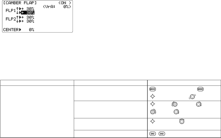
86
Flap Setting (CAMBER FLAP)(GLID):
CAMBER FLAP assigns the primary flap control [defaults to VR(A)] to allow
WULPPLQJLQÀLJKWRIWKHÀDSDFWLRQ
7KHXSGRZQWUDYHORIHDFKIODSFDPEHUIODSVFLP12) can be adjusted
LQGHSHQGHQWO\$OVRWKHFHQWHUSRVLWLRQRIÀDSVHUYRFDQEHRIIVHW
NOTE: If FLAP-TRIM is activated, you can not use CAMBER FLAP function
simultaneously.
[Note] When changing the polarity of a rate, "change rate dir?" is displayed for a check. Please set up after
pressing DIAL for 1 second and canceling an alarm display.
GOAL of EXAMPLE: STEPS: INPUTS:
Ex: Set the maximum travel of 35% of
WKHWRWDOÀDSWUDYHO
Open the CAMBER FLAP function. for 1 second. (If BASIC, again.)
C
to CAMBER FLAP.
$GMXVWWKHXSGRZQWULPDPRXQW
separately.
(Ex: adjust to 35%.)
C
to FLP1.VR(A). to 35%.
VR(A). to 35%. Repeat.
Option: Adjust the center position of
ÀDSVHUYR
C
to CENTER. to desired point.
Close menu.
Adjustability:
•Rate: -100% to +100%, with a default of +30%
•Center position (CENTER7KHRSHUDWLRQUHIHUHQFHSRLQWRIÀDSFDQEHRIIVHWWRZLWKDGHIDXOWRI
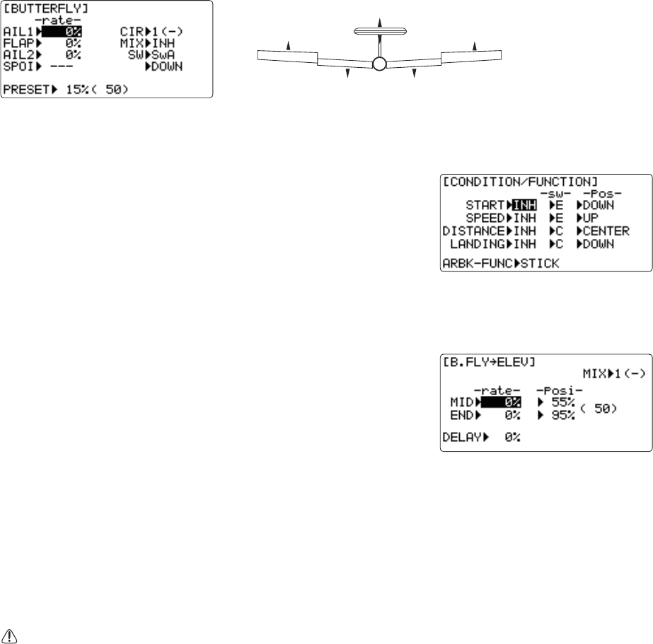
87
BUTTERFLY (crow) mixing (GLID):
BUTTERFLY (often called "crow"- see GLID S IRU GHWDLOV VLPXOWDQHRXVO\ PRYHV WKH ÀDS WZLQ DLOHURQV DQG HOHYDWRU
and is usually used to make steep descents or to limit increases in airspeed in dives. Separate two BUTTERFLY settings are
available. (CIR1CIR2)
Adjustability:
•Activation: Proportional by moving the THROTTLE STICK.
•Switch: Mix SWITCH is selectable.
A to H:SWITCH A to H
NULL: always on.
Also LOGIC SW (Lsw1 to 3) may be assigned. Set up LOGIC SW: See p. 38.
•Inversely proportional to THROTTLE STICK: provides a proportional increase in amount of airbrake action as
THROTTLE STICK is lowered (when SWITCH A (assignable) is in down position). Includes selectable stick position
where airbrake begins. If you would like to have the airbrake be directly proportional to throttle stick, you will need
to reverse the THR-REV function. Note that this changes the throttle stick direction for all models. See page 38 for
instructions.
•Elevator settings: (adjustable in the B.FLY-ELE)
B.FLY-ELE works linking with BUTTERFLY function. Elevator rate is adjustable in a
3 point curve.
Point 1: PRESET point. (Fixed)
Point 2: MID point. Position and rate are adjustable.
Point 3: END point. Position and rate are adjustable.
•Delayed reaction: You can suppress sudden changes in your model's attitude when BUTTERFLY is activated by setting the
delay (DELAYLWHPWRVORZGRZQWKHHOHYDWRUUHVSRQVHDOORZLQJWKHÀDSVDLOHURQVHOHYDWRUWRDOOUHDFKWKHLUGHVLUHGHQG
point together. A setting of 100% slows the servo to take approximately one second to travel the prescribed distance.
•Channels controlled:7ZLQDLOHURQVÀDSDQGVSRLOHUPD\EHVHWLQGHSHQGHQWO\LQBUTTERFLY, including set to 0 to have no
effect.
•Twin aileron servos: If AIL-DIFF function is inhibited, then AIL1 and AIL2 settings will have no effect.
• If AIL-DIFF is active, then CH1 and CH7 may be independently adjusted.
• Normally both ailerons are raised equally in BUTTERFLY, and the elevator motion is set to maintain trim when the ailerons
rise. Different amounts may be set for each aileron to correct for torque reactions and other unique characteristics of the
model.
Be sure you understand what dropping ailerons will do when in BUTTERFLY. Along with creating an enormous amount
of drag (desireble for spot landings), this also creates "wash-in", a higher angle of attack where the ailerons are, and
encourages tip stalling. If you are using this for aerobatic performance and not "sudden stops", consider raising the
DLOHURQVDQGGURSSLQJWKHÀDSVLQVWHDGDVVKRZQLQWKHGLDJUDPDERYH
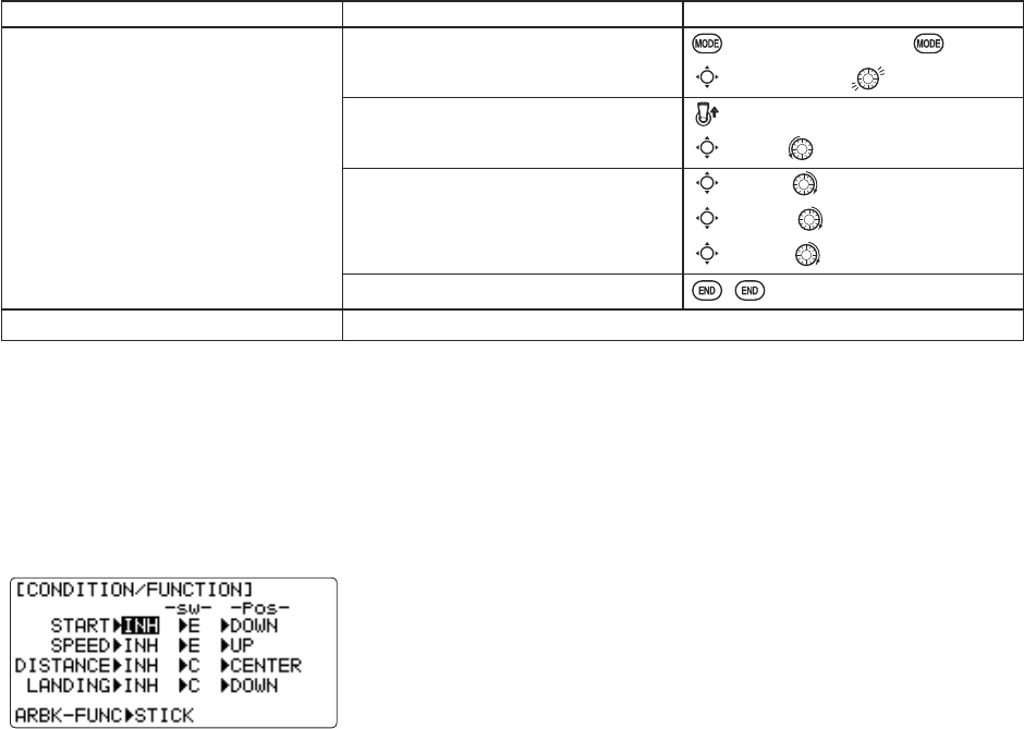
88
GOAL of EXAMPLE: STEPS: INPUTS:
Activate BUTTERFLY.
Adjust the aileron and flap travel to
75%.
Elevator settings are adjustable in the
B.FLY-ELE.
Mix switch is selectable.
Open the BUTTERFLY function. for 1 second. (If BASIC, again.)
C
to BUTTERFLY.
Activate the function. SWITCH A in up position.
C
to MIX to OFF.
Adjust the travels as needed.
(Ex: Ailerons each 75%, Flap 75%.)
C
to AIL1 to 75%.
C
to FLAP to 75%.
C
to AIL2 to 75%.
Close menu.
Where next? View additional model setups on the internet: www.futaba-rc.com\faq\
Channel 3's function selection (CONDITION/FUNCTION):
Channnel 3's function is selectable in the ARBK-FUNC item. (Throttle stick, switches, or knobs)
By choosing except STK, channel 3's function may be separated from BUTTERFLY's function, so channel 3 can be used
for other functions.
Adjustability:
•Channel 3's function:
STK:THROTTLE STICK
Sw-A to H:SWITCH A to H
Vr-A to Vr-E:KNOB A to E
89
HELICOPTER MODEL FUNCTIONS
Please note that nearly all of the BASIC menu functions are the same for airplane (ACRO setup), sailplane (GLID setups), and
helicopter (HELI) setups. The features that are identical refer back to the ACRO chapter. The Helicopter BASIC menu includes
the normal condition's throttle and collective pitch curves and revo. mixing. (idle-ups and throttle hold are advanced
features and are in the ADVANCE menu).
HELICOPTER FUNCTIONS.......................................... 89
Table of contents and reference info for helicopters . 89
Getting Started with a Basic Helicopter ................... 90
HELI BASIC MENU FUNCTIONS .................................. 93
MODEL Submenu: MODEL SELECT,COPY,NAME .......... 30
PARAMETER Submenu: RESET, MODUL, ATL, AILE-2,
CONTRAST,BACK-LIGHT,HOME-DISP,USER NAME,LOGIC
SW ............................................................................. 33
MODEL TYPE (PARAMETERS submenu) ........................ 93
Servo REVERSE ........................................................... 38
SWASH AFR (swashplate surface direction and travel
correction) (not in H-1) .............................................. 95
END POINT .................................................................. 39
Setting up the Normal Flight Condition ................... 97
THR-CUTVSHFLDOL]HGVHWWLQJVIRUKHOLFRSWHUVSHFL¿F
models) ..................................................................... 98
'XDO7ULSOH5DWHVDQG([SRQHQWLDOD/R,EXP) .......... 42
TIMER Submenu.......................................................... 45
Auxiliary Channel assignments and CH9 reverse (AUX-
CH) ............................................................................. 46
TRAINER ..................................................................... 47
TRIM and SUB-TRIM ................................................... 48
SERVO Display ........................................................... 49
Fail Safe and Battery FailSafe (F/S) ......................... 50
HELI ADVANCE MENU FUNCTIONS ............................. 99
THROTTLE HOLD .......................................................... 99
THR-CURVE,PIT-CURVE and REVO ............................. 100
Idle-ups ................................................................... 101
7ULPVRIIVHW............................................................. 102
Delay ....................................................................... 103
Hovering setups ...................................................... 104
+LJKORZSLWFK ........................................................ 105
Gyros and governors ............................................... 106
0L[HVGH¿QLWLRQVDQGW\SHV ..................................... 61
Linear, Prog. mixes 1-4 ............................................. 68
Curve, Prog. mixes 5-6 ............................................. 71
THROTTLE-NEEDLE ........................................................ 65
THROTTLE MIX ............................................................ 96
SWASH RING .............................................................. 96
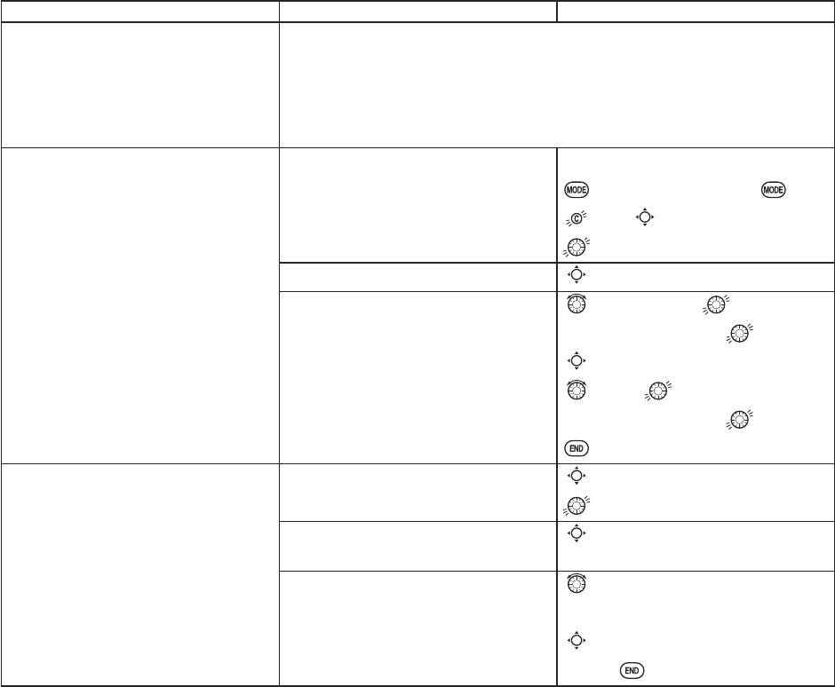
90
GETTING STARTED WITH A BASIC HELICOPTER
This guideline is intended to help you set up a basic (H-1) heli, to get acquainted with the radio, to give you a jump start on
using your new radio, and to give you some ideas and direction on how to do even more with this powerful system than
you may have already considered. It follows our basic format of all programming pages—a big picture overview of what
we're trying to accomplish; a “by name” description of the steps to help acquaint you with the radio; and then a step-by-
step instruction to leave out the mystery and challenge of setting up your model.
%ULHÀ\WKHW\SLFDOKHOLFRSWHU¶VFRQWUROVDUHDVIROORZV
•Aileron: changes cyclic lateral (roll) . Rolls the helicopter. Tilts the swashplate to the left or right. CH1.
•Elevator: changes cyclic pitch. Changes the helicopter’s angle of attack (nose up or nose down). Tilts the entire
swashplate fore and aft. CH2.
•Rudder: changes the angle of the tail rotor. Yaws the helicopter left or right. CH4.
•Collective Pitch: adjusts main rotor collective [angle of the paddles], changing the main blades’ pitch. Increased
collective pitch (with throttle) causes the helicopter to rise. Moves in conjunction with throttle on the THROTTLE
STICK. CH6.
•Throttle:RSHQVFORVHVFDUEXUHWRU0RYHVLQFRQMXQFWLRQZLWKFROOHFWLYHSLWFKRQWKHTHROTTLE STICK. CH3.
•REVO: mix that adds rudder in conjunction with pitch. This helps compensate for rotation of the helicopter caused by the
LQFUHDVHGHQJLQHWRUTXH1HYHUXVHUHYRPL[LQJZLWKDKHDGLQJKROG$9&6J\URWKHJ\URDOUHDG\GRHVWKLV
)RUDGGLWLRQDOGHWDLOVVHHWKDWIXQFWLRQVVHFWLRQLQWKLVPDQXDO²WKHSDJHQXPEHUVDUHLQGLFDWHGLQWKH¿UVWFROXPQIRU\RX
GOAL of EXAMPLE: STEPS: INPUTS:
Prepare your helicopter. Install all servos, switches, receiver per your model's instructions. Set all trims,
dials and sliders to neutral.
&RQ¿UPDOOFRQWUROOLQNDJHVDUHGHJUHHVRUSHULQVWUXFWLRQVIURPWKHVHUYR
horn to the ball link for proper geometry and that no slop is present.
Mechanically adjust all linkages to get as close as possible to proper control
throws and minimize binding prior to radio set up.
Select the proper MODEL TYPE for your
model. Ex: HELI (H-1). See p. 93.
[NOTE: This is one of several
functions for which the radio requires
confirmation to make a change.
Onlycritical changes require additional
key strokes to accept the change.]
(If the correct model type was already
displayed, be sure to do a model reset to
discard any unwanted settings.)
In the BASIC menu, open the PARAMETER
submenu.
Turn on the transmitter.
for 1 second. (If ADVANCE, again.)
then
C
to highlight PARAMETER.
to choose PARAMETER.
Go to MODEL TYPE.
C
to TYPE.
Select proper MODEL TYPE.
Ex: HELI(H-1). Confirm the change.
Close PARAMETER.
to HELICOPTER. for 1 second.
Are you sure? displays. WRFRQ¿UP
C
to SWASH.
to H-1. for 1 second.
Are you sure? displays. WRFRQ¿UP
to return to BASIC menu.
Then, NAME the model. P. 32.
(You do not need to do anything to
“ save” or store this data.)
In the BASIC menu, open the MODEL
submenu.
C
as needed to highlight MODEL.
to choose MODEL.
Go to MODEL NAME.
C
to NAME.
(First character of model'sname is highlighted.)
Input aircraft's name.
Close the MODEL submenu when done.
WRFKDQJH¿UVWFKDUDFWHU
When proper character is displayed,
C
to move to next character.
Repeat. to return to BASIC menu.
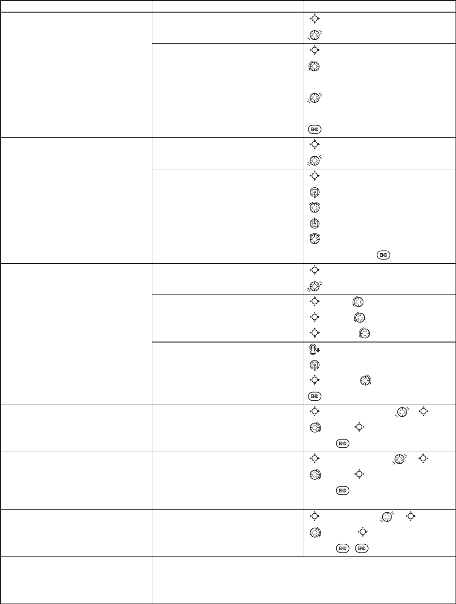
91
GOAL of EXAMPLE: STEPS: INPUTS:
Reverse servos as needed for proper
control operation. Ex: LEFT RUDDER
STICK results in leading edge of tail
rotor blades moving left. Reverse to
operate properly. P. 38.
In the BASIC menu, open REVERSE.
C
to REVERSE.
to choose REVERSE.
Choose desired servo and reverse its
direction of travel. (Ex: reverse rudder
servo.)
C
to CH4:RUDD.
so REV is highlighted.
Are you sure? Displays.
for 1 second.
Repeat as needed.
to return to BASIC menu.
Adjust Travels as needed to match
model's recommended throws (usually
listed as high rates).P. 39.
In the BASIC menu, choose END POINT.
C
to END POINT.
to choose END POINT.
Adjust the servos’ end points.
(Ex: elevator servo)
Return to BASIC menu.
C
to ELEV.
ELEVATOR STICK.
until up travel is as desired.
ELEVATOR STICK.
until down travel is as desired.
Repeat as needed.
Activate THR-CUT. P. 98. Open THROTTLE-CUT function.
C
to THROTTLE-CUT.
to choose THR-CUT.
Activate the function. Choose desired
switch and position to activate.
C
to MIX to OFF.
C
to SW. to C.
C
to POSI. to DOWN.
With THROTTLE STICK at idle, adjust
the rate until the engine consistently
shuts off, but throttle linkage is not
binding.1
Close.
C to down position.
THROTTLE STICK.
C
to RATE. until shuts off.
Set up throttle curve for normal.2
(Usually changes will not need to be
PDGHSULRUWR¿UVWÀLJKW3
Open the THR-CURV/NOR function.
Adjust if needed.
Close the function.
C
to THR-CURV/NOR. .
C
to 1 >.
to 5%.
C
to next point.
Repeat.
Set up collective pitch curve for normal
as base of -4, center of +5,end of
+8 to +10 degrees of blade pitch for
aerobatics.2 (If just learning to fly, ask
your instructor.) P. 97.
Open the PIT-CURV/NOR function.
Adjust each point to match desired
FXUYH([¿UVWSRLQW8%.)
Close the function.
C
to PIT-CURV/NOR. .
C
to 1 >.
to 8%.
C
to next point.
Repeat.
Set up revo. mixing for normal. (For
heading-hold gyros, inhibit revo.) P. 97.
Open the REVO./NOR function.
Adjust to your desired starting point.
(Ex: 10%.)
Close the function.
C
to REVO./NOR. .
C
to 1 >.
to 10%.
C
to next point.
Repeat.
&RQ¿UP*\URGLUHFWLRQ1RWHLIXVLQJ
DKHDGLQJKROG$9&6J\URXVHWKH
GYRO programming for proper setup.
See p. 106.)
With radio on, move helicopter’s tail to the right by hand.
The gyro should give right rudder input (leading edge of the tail rotor blades
move left).
If the gyro gives the opposite input, reverse direction on the gyro unit itself.
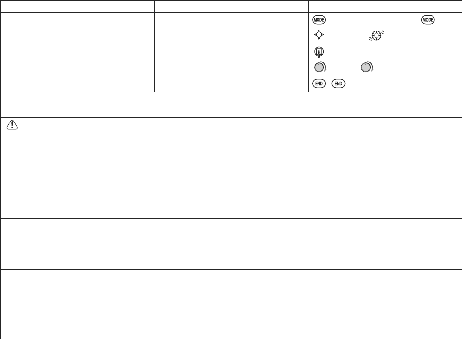
92
GOAL of EXAMPLE: STEPS: INPUTS:
Learn how to operate HOVERING PITCH
and HOVERING THROTTLE. See p. 104.
Notice at half throttle, the VR(C) dial
adjusts the throttle separately from the
pitch. VR(A) adjusts the pitch separately
from the throttle.
for 1 second. (If ADVANCE, again.)
C
to SERVO.
throttle to center
VR(C) VR(A) center dials.
%H VXUH WR IROORZ \RXU PRGHO¶V LQVWUXFWLRQV IRU SUHÀLJKW FKHFNV EODGH WUDFNLQJ HWF 1HYHU DVVXPH D VHW RI EODGHV DUH
properly balanced and will track without checking.
Check receiver battery voltage! Always check voltage with a voltmeter prior to each and every engine start.(Never
DVVXPHEHLQJSOXJJHGLQDOOQLJKWPHDQV\RXUUDGLRJHDULVUHDG\WRÀ\,QVXI¿FLHQWFKDUJHELQGLQJVHUYROLQNDJHV
and other problems can result in a dangerous crash with the possibility of injury to yourself, others and property.
&RQ¿UPWKHVZDVKSODWHLVOHYHODWWUDYHO$GMXVWDUPVLIQHHGHG
Apply full collective and check that the swashplate remained level and there is no binding. Repeat for full cyclic pitch and
roll. If not, adjust as needed to correct in END POINT: see p. 39.
Important note: prior to setting up throttle hold, idle-ups, offsets, etc, be sure to get your normal condition operating
properly.
Checking setup prior to going airborne: Check voltage! Then, with the assistance of an instructor, and having completed
all range checks, etc, gradually apply throttle until the helicopter becomes “light on the skids.” Adjust trims as needed to
correct for any roll, pitch, or yaw tendencies. If the tail “wags,” the gyro gain is too high. Decrease gyro gain.
Where next? (Other functions you may wish to set up for your model.)
THROTTLE HOLD: P. 99.
SUB-TRIM p. 49 and separate trims for conditions (OFFSETS): p. 102.
Governor setup: p. 108.
IDLE-UP p. 101.
DELAYs to ease servo response when switching idle-ups: p. 103.
Rudder-to-throttle and other programmable mixes p. 68.
1 Periodically move the throttle stick to full and back down to ensure proper servo settings.
2 It is critical that dials A and C be centered when the pitch and throttle curves are setup.
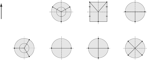
93
HELI-SPECIFIC BASIC MENU FUNCTIONS
MODEL TYPE: This function of the PARAMETER submenu is used to select the type of model programming to be used. Before
GRLQJDQ\WKLQJHOVHWRVHWXS\RXUPRGHO¿UVW\RXPXVWGHFLGHZKLFKMODEL TYPEEHVW¿WV\RXUDLUFUDIW,I\RXUWUDQVPLWWHU
is a 10CAG, the default is ACRO. If it is a 10CH, the default is HELI(H-1).
HELICOPTER SWASHPLATE TYPES:
The 10CG radios support 8 basic swashplate setups, including "single servo" (H-1-most helicopters use this type) and 7
types of CCPM (cyclic and collective pitch mixing). A "single servo" swashplate uses one servo for each axis: aileron,
elevator (cyclic pitch), and collective pitch. CCPM helicopters utilize a combination of servos working together to achieve
the 3 axes of motion. There are 7 basic CCPM types, displayed below. CCPM has several advantages, the most obvious
of which is far less mechanical complexity to properly move the swashplate of the helicopter. Additionally, several servos
working in unison (ex: HR3, all 3 servos together create elevator movement) dramatically increases the torque available as
well as the precision and centering.
Please note that some helicopters are type HR3 or HN3, except off by 180 degrees. For example, the Kyosho® Caliber is
HR3 but with the 2 parallel servos to the rear of the helicopter, not front. If your model's swashplate is off by 180 degrees,
you will still use that swashplate type, but also use SWASH AFR (p.95) to adjust the functions as needed until it operates
properly. Additionally, different angles of CCPM may also be created utilizing the fully assignable programmable mixes.
(See our Frequently Asked Questions area at www.futaba-rc.com\faq\.)
Not operating quite like you expected? ,QPDQ\&&30LQVWDOODWLRQV\RXQHHGWRHLWKHUUHYHUVHWKHGLUHFWLRQRIDVSHFL¿F
function (SWASH AFR) or reverse a single servo's direction (REVERSE). See SWASH AFR for details. (p.95)
Swashplate Types
HR3H-1 H-3
ELE ELE
ELE1
ELE2
120˚
120˚120˚
PIT
(AIL)
AIL
(PIT)
PIT
(AIL)
AIL
(PIT)
HN3
120˚
120˚
120˚
ELE
PIT
AIL
HE3
ELE
PIT
(AIL)
AIL
(PIT)
PIT
(AIL)
AIL
(PIT)
H-2
PIT
FRONT
AIL
H-4
ELE1
ELE2 AIL
PIT
H4X
(Normal linkage type)
H-1:each servo linked
to the swashplate
independently.
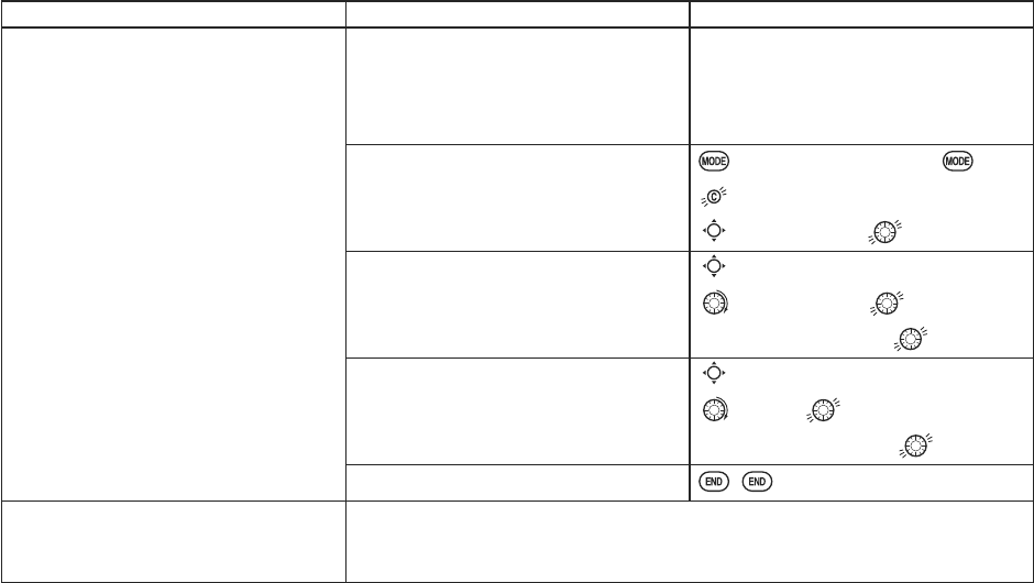
94
GOAL of EXAMPLE: STEPS: INPUTS:
Change the MODEL TYPE and SWASH
TYPE of model #3 from aircraft to 120
degree CCPM with 2 servos working in
unison for collective pitch and aileron
[HELI(HR3)].
Confirm you are currently using the
proper model memory. (example: 3)
On home screen, check model name and
# on top left.
If it is not the correct model (example:3),
see MODEL SELECT, p. 25.
Open PARAMETER submenu. for 1 second. (If ADVANCE, again.)
to 2nd page of menu.
C
to PARAMETER.
Select proper MODEL TYPE.
(HELICOPTER)
&RQ¿UPWKHFKDQJH
C
to TYPE.
to HELICOPTER. for 1 second.
Are you sure? displays. WRFRQ¿UP1
Change to the desired SWASH TYPE
(example, HR3.)
&RQ¿UPWKHFKDQJH
C
to SWASH.
to HR3. for 1 second.
Are you sure? displays. WRFRQ¿UP
Close.
Where next? If a single servo is not operating properly, REVERSE: see p. 38.
If a control is operating backwards (i.e. Elevator), see SWASH AFR, p. 95.
If unsure see SWASH AFR.
1Radio emits a repeating “beep” and shows progress on screen as the model type is being changed. Note that if the power switch is turned off prior to
completion, the model type will not be changed.
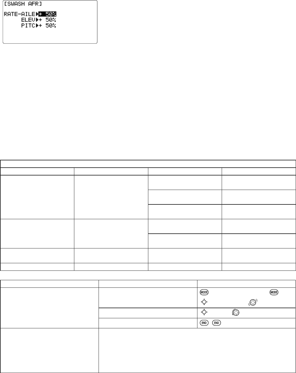
95
SWASH AFR (not in SWH1):
Swashplate function rate settings (SWASH AFRUHGXFHLQFUHDVHUHYHUVHWKH UDWH
(travel) of the aileron, elevator (except H-2 ) and collective pitch functions,
adjusting or reversing the motion of all servos involved in that function, only
when using that function. Since these types utilize multiple servos together to
create the controls, simply adjusting a servo's REVERSE or END POINT would not
properly correct the travel of any one control. Since H-1 uses one servo for each
function, there is no need for AFR in H-1.
This is fairly hard to explain but easy to see, so let's set up Kyosho® Caliber's swashplate settings as an example. With
everything installed per factory instructions, set the model to HELI(HR3). Now let's adjust the swashplate properly.
6LQFH DLOHURQ DOZD\V XVHV QR PRUH WKDQ VHUYRV FKHFN LW ¿UVW (LWKHU ERWK RSHUDWH SURSHUO\ QR FKDQJH QHHGHG ERWK
operate backwards (reverse the whole function), or one servo operates backwards (reverse that servo alone).
Next check elevator. Remember, the aileron servo(s) operate correctly, so if elevator does not, we should only have 2
choices left—the whole function needs to be reversed, or the servo(s) not shared with aileron need to be reversed.
Last is collective. If aileron and elevator are working properly, the only thing that could be wrong is the whole direction
collective operates (reverse the whole function). In our example, HR3 is 180 degrees off from the swashplate of the Caliber.
Therefore, it is very likely that several functions will not operate properly. The collective pitch operation is backwards;
but reversing all three servos would also reverse the aileron and elevator operations. Changing the collective pitch rate,
however, from +50% to -50%, will reverse the collective pitch without affecting the aileron action.
CHECKING FOR PROPER MOTION ON AN HR3 SWASHPLATE
HR3 Swash Type PROPER MOTION WRONG MOTION HOW TO FIX
AILERON STICK. Swashplate tilts right. Swashplate tilts left. Reverse AIL setting in SWASH
to -50%.
Back of Swashplate moves
up.
Ch6 servo moves incorrectly;
REVERSE.
Back of Swashplate moves
down.
Ch1 servo moves incorrectly;
REVERSE.
ELEVATOR STICK. Front of swash plate moves
down; back of swashplate
moves up.
Swashplate moves the
opposite.
Reverse ELE setting in SWASH.
(ex: +50 to -50)
Entire swashplate moves up. Ch2 servo moves incorrectly;
REVERSE.
RUDDER STICK. The leading edges of tail
blades rotate left.
Blades rotated right. REVERSE the rudder servo.
THROTTLE STICK. Entire Swashplate lifts. Swashplate lowers. Reverse PIT setting in SWASH.
GOAL of EXAMPLE: STEPS: INPUTS:
Adjust the travel of the collective pitch
from +50% to -23%, reversing the travel
of all 3 servos and decreasing their
travel in collective pitch only, on an
HR3 SWASH TYPE.
Open SWASH AFR function. for 1 second. (If ADVANCE, again.)
C
to SWASH AFR.
Adjust PITC travel to -23%.
C
to PITC. to -23%.
Close the menu.
Where next? &RQ¿UPWKHVZDVKSODWHLVOHYHODWWUDYHO$GMXVWDUPVLIQHHGHG
Apply full collective and check that the swashplate remained level. If not,
adjustservois travels as needed to correct. END POINT: see p. 39.
Set up the normal condition: (THR-CURV/NOR, PIT-CURV/NOR, REVO./NORM):
see p. 97.
Set up D/R,EXP: see p. 42.
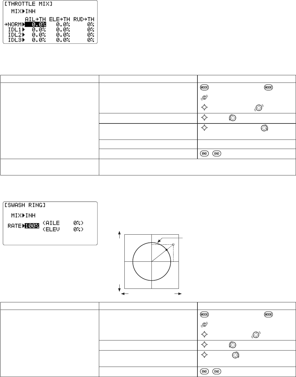
96
Throttle Mixing (THROTTLE MIX):
This function can be set for each flight condition, and is used to correct the
tendency of the model to change altitude when the rotor is tilted by aileron,
elevator, and rudder controls.
Adjustability:
0L[LQJPD\EHVHWIURPWRHDFKÀLJKWFRQGLWLRQ
GOAL of EXAMPLE: STEPS: INPUTS:
Correct the tendency of the model to
change altitude.
Open THROTTLE MIX function. for 1 second. (If BASIC, again.)
to 2nd page of ADVANCE menu.
C
to THROTTLE MIX.
Activate the function.
C
to MIX to ON.
Adjust the rate.
Ex: IDL1 (AIL to TH) 10%
C
to IDL1 (AIL to TH) to 10%.
Repeat as needed.
Close the menu.
Where next? HI/LOW-PIT : see p. 105.
GOVERNOR set up: see p. 108.
Swash Ring (SWASH RINGOLPLWVWKHVZDVKSODWHWUDYHOWRZLWKLQD¿[HGUDQJH
7KLVIXQFWLRQOLPLWVWKHVZDVKWUDYHOWRZLWKLQD¿[HGUDQJHWRSUHYHQWGDPDJLQJ
of the swash linkage by simultaneous operation of the ailerons and elevators. It
is effective in 3D aerobatics which use a large travel.
GOAL of EXAMPLE: STEPS: INPUTS:
To prevent damaging of the swash
linkage by simultaneous operation of
the ailerons and elevators, set the limit
point where swash throw stops.
*Adjust the rate at the maximum swash
tilt by simultaneous operation of the
ailerons and elevators
Open SWASH RING function. for 1 second. (If BASIC, again.)
to 2nd page of ADVANCE menu.
C
to SWASH RING.
Activate the function.
C
to MIX to ON.
Adjust the rate.
Ex: 90%
C
to RATE to 90%.
Close the menu.
•Swash travel by simultaneous operation of
the ailerons and elevators is limited within the
circle(SWASH RING rate).
Adjustability:
• Initial value: 100%.
• Adjustment range: 0 to 200%.
Aileron operation
Elevator operation
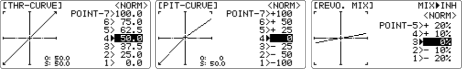
97
Setting up the Normal Flight Condition:7KH1RUPDOÀLJKWFRQGLWLRQLVW\SLFDOO\XWLOL]HGIRUKRYHULQJ7KHWKURWWOHDQG
FROOHFWLYHSLWFKFXUYHVDUHDGMXVWHGWRSURYLGHFRQVLVWHQWHQJLQH530GHVSLWHWKHLQFUHDVHGHFUHDVHLQFROOHFWLYHSLWFKRI
the blades. This keeps the engine from “bogging down” under excessive load (like trying to accelerate a car on a steep hill
LQWKJHDURUH[FHVVLYH530XQGHULQVXI¿FLHQWORDGOLNHÀRRULQJWKHWKURWWOHZKLOHLQQHXWUDOULVNLQJHQJLQHGDPDJH
$VWKHFXUYHVDQGUHYRPL[LQJDUHDOOLQWHUUHODWHGZHZLOOGLVFXVVDOOWKUHH¿UVWWKHQFRPSOHWHDVDPSOHVHWXS
Note that the normal throttle, pitch and revo curves are all available in the BASIC menu for simplicity. These may also be
updated later in the ADVANCE menu with the settings for the other 4 conditions [idle-up 1 (IDL1), idle-up 2 (IDL2) and idle-
up 3 (IDL3), plus throttle hold (HOLD)]. Note: The throttle and pitch curves for the normal condition are always on. They
cannot be inhibited. The other four conditions are activated with their throttle curves or throttle hold. For idle-ups, see p.
90. For throttle hold, see p. 99.
•THR-CURV/NOR: inputs the normal (NORM) throttle curve, which is usually not a linear response to THROTTLE STICK
motion. Adjusting point 4 of the curve adjusts the engine’s RPM at the THROTTLE STICK midpoint . the desired
position for hovering. The other 6 points are then adjusted to create the desired idle and maximum engine speed, and a
smooth transition in-between. For more on throttle curves, see p. 101.
•PIT-CURV/NOR: inputs the normal (NORM) collective pitch curve, the collective pitch curve for flight near hover. The
normal collective pitch curve is adjusted to match the throttle curve, providing the best vertical performance at a constant
engine speed, with a starting curve of .4 base, +5 neutral, and +8 to +10 degrees of blade pitch maximum*. You can
program the response over a 7-point curve for the best collective pitch angle relative to THROTTLE STICK movement.
For more on collective pitch curves, see p. 101.
•REVO./NORM: mixes collective pitch commands to the rudder (a PITCH-RUDDER mix) to suppress the torque generated
by changes in the main rotor's collective pitch angle, keeping the model from yawing when throttle is applied. REVO. is
H[WUHPHO\KHOSIXOLQ³WDPLQJWKHWDLO´RIPRGHOVQRWXVLQJKHDGLQJKROGAVCS gyros.
NOTE: There are three revo. mixes available: normal (NORMLGOHXS
IDL1/2), and idle-up 3 (IDL3). All 3 are
adjustable in the ADVANCEPHQX1HYHUXVHUHYRPL[LQJLQFRQMXQFWLRQZLWKKHDGLQJKROG$9&6J\URV)RUGHWDLOVRQ
revo, including default points for clockwise and counterclockwise rotating rotors, see p. 101.
7KHVH GHIDXOW UHFRPPHQGDWLRQV DVVXPH \RX DUH GRLQJ IRUZDUG ÀLJKW ,I \RX DUH MXVW OHDUQLQJ SOHDVH IROORZ \RXU LQVWUXFWRU¶V JXLGDQFH 6RPH
LQVWUXFWRUVOLNHDEDVHSRLQWIRUWUDLQLQJVRWKDWWKHKHOLFRSWHUFRPHVGRZQYHU\VORZO\HYHQLI\RXULQVWLQFWVSXOOWKHWKURWWOHFROOHFWLYHVWLFNWR
the bottom in a hurry.
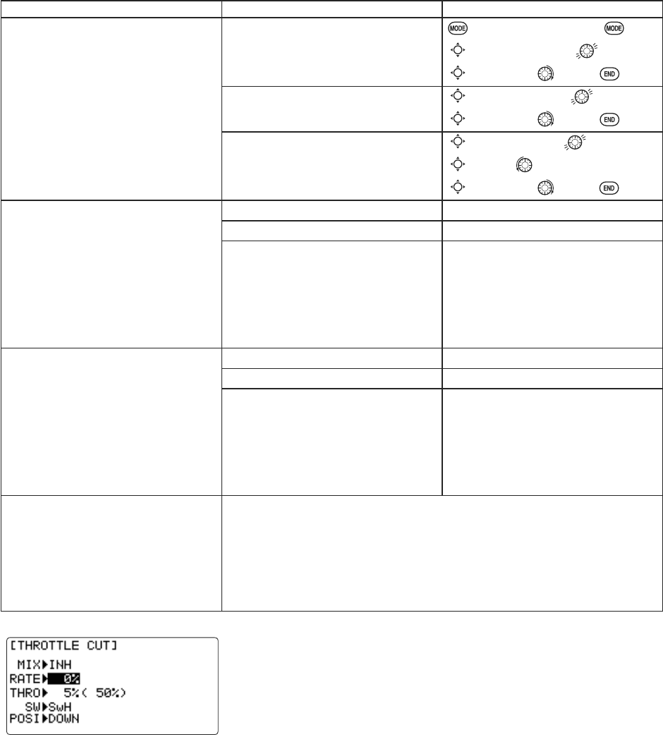
98
GOAL of EXAMPLE: STEPS: INPUTS:
Set up Normal Flight Condition
Throttle/Collective Pitch Curves and
Revo.
Base point: Adjust base point of throttle
curve until engine idles reliably on
ground. Adjust base point of collective
pitch curve to achieve -4 degrees of
blade pitch. Apply throttle until the
model sits ‘light’ on its skids. Adjust
base point of REVO. until model does not
rotate its nose at all.
Open the THR-CURV/NOR function.
$GMXVWWKH¿UVWSRLQW([5%.)
for 1 second. (If ADVANCE, again.)
C
to THR-CURV/NOR.
C
to POINT-1. to 5%.
Open the PIT-CURV/NOR function.
$GMXVWWKH¿UVWSRLQW([8%.)
C
to PIT-CURV/NOR.
C
to POINT-1. to 8%.
Open the REVO. /NORM function.
$GMXVWWKH¿UVWSRLQW([4%.)
C
to REVO. /NORM.
C
to MIX. to ON.
C
to POINT-1. to 4%.
Hover point: Adjust collective pitch
curve to +5 degrees. Ease heli into a
KRYHU/DQGVKXWHQJLQHRII$GMXVW
throttle curves and rudder trim. Repeat
until model hovers smoothly at half
WKURWWOH5DSLGO\DSSO\WKURWWOHIURP
WRVWLFN$GMXVWREVO. points 2 and 3
until the model does not rotate its nose
up on throttle application.
Adjust THR-CURV/NOR. Repeat above as needed.
Adjust PIT-CURV/NOR. Repeat above as needed.
Adjust REVO. /NORM. Repeat above as needed.
High point: Adjust collective pitch
curve to +8 to +10 degrees. From hover,
throttle up rapidly. If engine bogs,
increase the throttle curve. If engine
over-revs, increase the collective pitch
curve at points 6 or 7. Apply full throttle
while hovering, then descend back to
hover. Adjust REVO. until the nose does
not change heading.
Adjust THR-CURV/NOR. Repeat above as needed.
Adjust PIT-CURV/NOR. Repeat above as needed.
Adjust REVO. /NORM. Repeat above as needed.
Where next? GYRO function: see p. 107.
Adjust HOV-THR and HOV-PIT if needed: see p. 104.
Setting up Throttle Hold: see p. 99.
Setting up idle-ups 1, 2 and 3: Throttle and collective pitch curves and revo.
mixing (THR-CURVE, PIT-CURVE, REVO. MIX): see p. 101.
GOVERNOR function: see p. 108.
D/R,EXP: see p. 42.
THROTTLE CUT:
The THROTTLE-CUT function is used to kill the engine at the end of a flight.
The engine can be stopped with one touch of any switch, eliminating the need
WR PRYH WKH WULP WR NLOO WKH HQJLQH DQG WKHQ UHDGMXVW SULRU WR HDFK ÀLJKW 7KH
helicopter THROTTLE-CUTLQFOXGHVDQ212))WKURWWOHSRVLWLRQQRUPDOO\D
little above idle). You must move the THROTTLE STICK back below the set
point before the THROTTLE-CUT function can be reset, to avoid sudden engine
acceleration. For a detailed example of throttle cut setup, see ACRO p. 41.
Note: Be sure to add the step of setting a trigger point by cursoring to THRO, then putting the THROTTLE STICK in the
desired position and pressing and holding the dial for one second. Notice that this function cannot be reversed to trigger
only above the stick point.
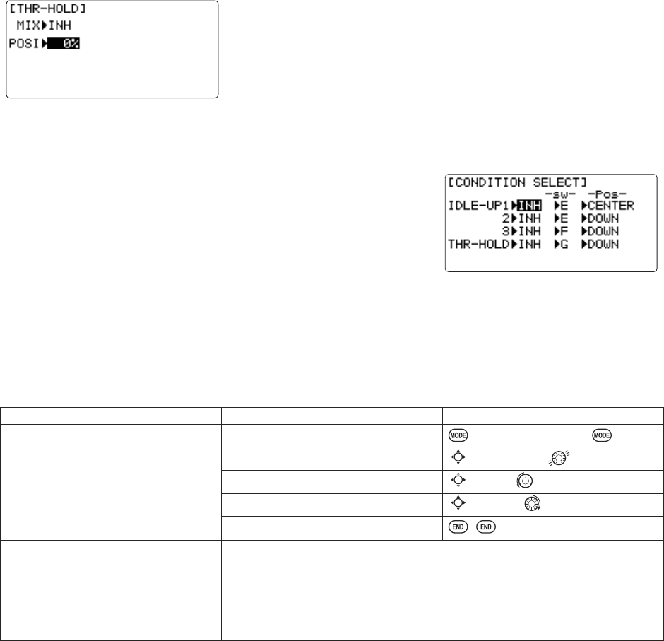
99
HELI-SPECIFIC ADVANCE MENU FUNCTIONS
THR-HOLD: This function holds the engine in the idling position and disengages it from the THROTTLE STICK when
SWITCH E (10CHG) or G (10CAG) is moved. It is commonly used to practice auto-rotation.
Prior to setting up THR-HOLD, hook up the throttle linkage so that the carburetor
is opened fully at high throttle, then use the digital trim to adjust the engine idle
position. To have THR- HOLD maintain idle, move the THROTTLE STICK to the
idle position, then move the hold SWITCH on and off and keep changing the
offset value until the servo does not move. To lower the engine idle speed, or if
you want to shut off, input a more negative number.
Adjustability:
•Idling position: Range of -50% to +50% centered about the throttle idle position to get the desired engine RPM.
•Switch assignment: Assigned to SWITCH G (10CAG) or E (10CHG) down.
Adjustable in the CONDITION SELECT (THR-HOLD item).
(2-position type switch only)
•Throttle curve: Since the throttle is moved to a single preset position, no curve
is available for THR-HOLD.
•Collective pitch curve: Independent curve, typically adjusted to create a blade
pitch range of -4% to +10% to +12%, is automatically activated with THR-
HOLD.
•Revo. mix: Since revo. mix adjusts for torque from the engine, no revo. mix is available for THR-HOLD.
•Priority: The throttle hold function has priority over idle-up. Be sure that the throttle hold and idle-up SWITCHES are
in the desired positions before trying to start the engine. (We recommend starting your engine in throttle hold for safety
reasons.)
•Gyro: Gyro programming includes an option to have a separate gyro setting for each condition, including THR-HOLD.
This avoids the potential problem of the user being in the wrong gyro setting when going to THR-HOLD, resulting in an
improper rudder offset and the model pirouetting.
GOAL of EXAMPLE: STEPS: INPUTS:
Set up throttle hold.
Determine desired throttle position by
idling engine, turn on THR-HOLD, and
adjust percentage as required to reach
the desired running point.
Open THR-HOLD function. for 1 second. (If BASIC, again.)
C
to THR-HOLD.
Activate the function.
C
to MIX. to OFF.
Set desired engine position.
C
to POSI. to desired percent.
Close.
Where next? PIT-CURVE for THR-HOLD: see p. 101.
DELAY for THR-HOLD (to ease collective pitch response): see p. 103.
GYRO setup: see p. 107.
Setting up the Idle-Ups: Throttle and Collective pitch Curves and Revo.
Mixing(TH-CURVE, PIT-CURVE, REVO. MIX) for idle-ups: see p. 101.
D/R,EXP: see p. 42.
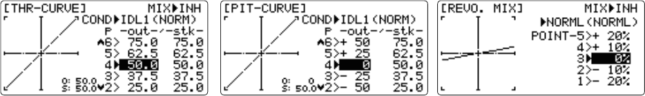
100
THR-CURVE and PIT-CURVE: These 7-point curves are utilized to best match the blade collective pitch to the engine RPM for
consistent load on the engine. Curves are separately adjustable for normal, idle-up 1, idle-up 2, and idle-up 3. In addition,
a separate collective pitch curve is available for throttle hold. Sample curves are displayed in the appropriate setup types (ex:
QRUPDOÀLJKWFRQGLWLRQSIRUFODULW\
Suggested defaults:
• Normal: Collective pitch curve that results in points 1, 4 and 7 providing .4, +5, (+8 to +10)* degrees pitch. A throttle
curve setting of 0, 25, 36, 50, 62.5, 75, 100%.
,GOHXSV,GOHXSVDQGDUHW\SLFDOO\WKHVDPHH[FHSWIRUWKHJ\URVHWWLQJVZLWKRQHEHLQJKHDGLQJKROG$9&6
and the other being normal mode. The pitch curve will likely be similar to the normal curve above.
• Idle-up 3: Collective pitch curve that results in points 1, 4 and 7 providing (.8 to .10), 0, (+8 to +10) degrees. A throttle
curve of 100, 75, 62.5, 50, 62.5, 75, 100 to provide full throttle for inverted maneuvers.
• Throttle Hold pitch curve: Start with the normal pitch curve (for inverted autos, start from the idle-up 3 pitch curve), but
LQFUHDVHWKHODVWSRLQWDSSUR[LPDWHO\LIDYDLODEOHWRHQVXUHVXI¿FLHQWSLWFKDWODQGLQJ
7KHVH GHIDXOW UHFRPPHQGDWLRQV DVVXPH \RX DUH GRLQJ IRUZDUG ÀLJKW ,I \RX DUH MXVW OHDUQLQJ SOHDVH IROORZ \RXU LQVWUXFWRU¶V JXLGDQFH 6RPH
LQVWUXFWRUVOLNHDEDVHSRLQWIRUWUDLQLQJVRWKDWWKHKHOLFRSWHUFRPHVGRZQYHU\VORZO\HYHQLI\RXULQVWLQFWVSXOOWKHWKURWWOHFROOHFWLYHVWLFNWR
the bottom in a hurry.)
Adjustability:
• Normal condition curves are editable in the BASIC menu for convenience.
• All curves may be adjusted in the ADVANCE menu.
• Automatically selected with the proper condition.
7KHLGOHXSFXUYHV DUH SURJUDPPHG WR PDLQWDLQFRQVWDQW530HYHQZKHQWKHFROOHFWLYHSLWFKLV UHGXFHG GXULQJ ÀLJKW
(including inverted).
• To change which condition’s curve is being edited, cursor up to COND> and change the curve named.
• For clarity, the name of the condition currently active (switched on in the radio) is shown in parentheses behind name of
condition whose curve is being edited. (Example: see curve displays below. Note that the normal condition is active but
the idle-up 1 condition’s curves are currently being edited.
•Moving and deleting the curve point: The curve point (-stk-) can be moved to the left or right by turning the DIAL (up to
LQIURQWRIWKHDGMRLQLQJSRLQWDQGGHOHWHGUHWXUQHGE\SUHVVLQJWKHDIAL for one second alternately.
•Copying the curve: To copy the current curve onto another condition’s curve, cursor up to COND> and press the DIAL for
one second. Then select to desired condition and press the DIAL for one second.
• Idle-ups and throttle hold pitch curves may be edited even before the conditions have been made active. Activating their
throttle curves activates these conditions.
REVO. MIX: This 5-point curve mix adds opposite rudder input to counteract the changes in torque when the speed and
collective pitch of the blades is changed.
Adjustability:
• Three separate curves available: normal for hovering; idle-ups 1 and 2 combined; and idle-3.
• Normal condition curves are editable in the BASIC menu for convenience.
• All curves may be adjusted in the ADVANCE menu.
&RUUHFWPL[LVDXWRPDWLFDOO\VHOHFWHGLQÀLJKWZLWKHDFKFRQGLWLRQDQGDXWRPDWLFDOO\DFWLYDWHGZKHQWKHWKURWWOHVHWXSIRU
that condition is activated in the programming (i.e. THROTTLE HOLD or THR-CURVE.)
• To change which condition’s curve is being edited, cursor up above POINT5 and select. For clarity, the name of the
condition currently active (switched on at the radio) is shown in parentheses behind the name of the condition whose
curve is being edited.
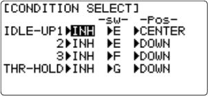
101
Revo. mixing rates are 5-point curves. For a clockwise-turning rotor, the rudder is mixed in the clockwise direction
when collective pitch is increased; for counterclockwise-turning, the opposite. Change the operating direction setting by
changing the signs of the numbers in the curve from plus (+) to minus (-) and vice versa. Suggested defaults:
Clockwise rotation: -20, -10, 0, +10, +20% from low throttle to high.
Counterclockwise rotation: +20, +10, 0, -10, -20% from low throttle to high.
Adjust to the actual values that work best for your model.
Revo. curves for idle-ups are often v-shaped to provide proper rudder input with negative pitch and increased throttle
GXULQJ LQYHUWHG ÀLJKW 5XGGHU LV QHHGHG WR FRXQWHU WKH UHDFWLRQ ZKHQHYHU WKHUH LV LQFUHDVHG WRUTXH ,Q LQYHUWHG ÀLJKW
throttle stick below half has increased throttle and negative pitch, therefore increasing torque and rotating the helicopter
unless the revo. mix is also increasing appropriately.)
IDLE-UPS: DGGLWLRQDO ÀLJKW FRQGLWLRQV DYDLODEOH VSHFL¿FDOO\ IRU KHOLFRSWHUV 7KHVH DGGLWLRQDO ÀLJKW FRQGLWLRQV FRQWDLQ
different throttle curves, collective pitch curves, revo. mixing, and trims (except IDLE-3) to make the helicopter perform
certain maneuvers more easily. Lastly, the gyro and dual rate functions may be set to provide separate rates per condition
selected, including one for each idle-up.
2QHRIWKHPRVWFRPPRQÀLJKWFRQGLWLRQVFDQHDVLO\ÀLSIURPXSULJKWWRLQYHUWHGDQGEDFN7RGRVRWKHSLWFKFXUYHLVVHW
to 0 pitch at half stick, positive pitch (climb upright) above half, and negative pitch (climb when inverted) below half stick.
The throttle curve is adjusted to allow the engine to run consistently throughout the changes in pitch.
Additional idle-ups may be used to maximize the helicopter's flight characteristics in certain types of flight (i.e. fast
forward motion, backward) or maneuvers (loops, rolls, stall turns), or even the same maneuver but changing from heading-
KROG$9&6J\URPRGHWRQRUPDOJ\URPRGH7KH&SURYLGHVLGOHXSVWRDOORZWKHPRGHOHUDGGLWLRQDOVHWXSVDORQJ
ZLWKWKHQRUPDOÀLJKWFRQGLWLRQ1RWHWKDWIDL3 does not include governor settings.)
Adjustability:
•SWITCH G (10CAG) or E (10CHG) is programmed for normal (NORM), idle-
up 1 (IDLE-UP1), and idle-up 2 (IDLE-UP2) curves.
Adjustable in the CONDITION SELECT (IDLE-UP1/2,IDLE-UP3 items).
(IDLE-UP1/2 3-position type switch only, IDL3 2-position type switch only)
• Activated with the throttle curve for that condition in THR-CURVE.
• Curves are adjusted to maintain constant RPM even when the collective pitch
is negative (inverted).
• Note that REVO.mixing has one curve for idle-ups 1 and 2 and a second curve just for idle-up3.
• Gyro settings may be set separately for each idle-up. (See p. 101.)
*RYHUQRU VHWWLQJV PD\ EH VHW XS WR IROORZ 1RUPDO,GOH,GOH EXW GR QRW RIIHU D VHWWLQJ WR DGMXVW IRU HDFK RI WKH
conditions like gyro. (See p. 101.)
• Activating OFFSET makes the TRIM LEVERS adjust the trim separately in each of the idle-up conditions.
For an example of throttle and pitch curves and revo, please see Normal Flight Condition Setup, p. 97.
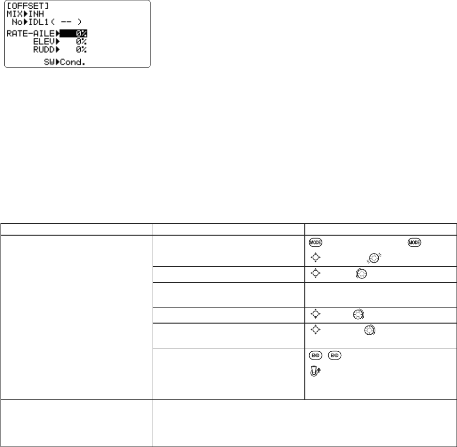
102
OFFSET: Optional separate trims in addition to those for the normal condition. This function is used to automatically change
WKH WULP RI D KHOLFRSWHU IRU H[DPSOH ZKHQ WUDQVLWLRQHG IURP KRYHU WR À\LQJ DW KLJK VSHHG$ FORFNZLVHURWDWLRQ URWRU
helicopter tends to drift to the right at high speed, so an aileron offset may be applied to offset the helicopter to the left.
The necessary elevator offset varies with model geometry, so it must be determined by noting collective pitch changes at
high speed. The rudder offset is affected by both revo. mixing and trim lever movement while in the offset function.
Adjustability:
• Complete switch assignability, plus a CONDITION SELECT RSWLRQ WKDW FUHDWHV
switches between individual trims for each of the idle-ups.
• When OFFSET is active (its switch is on), moving the TRIM LEVERS adjust
the stored offset, not the trims in the normal condition.
• When OFFSET is inactive (its switch is off), the OFFSET and any trim adjustments
WRLWKDYHQRHIIHFWPRGHOREH\VWKHWULPVHWWLQJVRIWKHFXUUHQWO\DFWLYHÀLJKW
condition.)
• When OFFSETLVLQKLELWHGWULPDGMXVWPHQWVPDGHLQDQ\ÀLJKWFRQGLWLRQDIIHFW
DOOÀLJKWFRQGLWLRQV
• Rapid jumps caused by large offsets can be slowed using the DELAY function.
*During OFFSET operation, the aileron, elevator, and rudder travels are displayed on each trim
display in the Startup screen.
NOTE: 5HPHPEHU RIIVHWV DQG UHYR PL[HV DUH QRW UHFRPPHQGHG ZKHQ XVLQJ KHDGLQJKROG$9&6 J\URV EHFDXVH WKH\
FRQÀLFWZLWKWKHDXWRPDWLFFRUUHFWLRQVWRWULPDQGWRUTXHWKDW$9&6SURYLGHV
GOAL of EXAMPLE: STEPS: INPUTS:
Set up separate trims for each of the
three idle-up conditions.
Adjust the idle-up 2 rudder trim to
correct for torque at high speeds.
Open the OFFSET function. for 1 second. (If BASIC, again.)
C
to OFFSET.
Activate the function.
C
to MIX. to OFF or ON.
Change switch setting to Cond.
(No need to change SW.)
already Cond.
Select IDL2.
C
to No. to IDL2.
Adjust trim settings as needed.
(Ex:rudder to +8%.)
C
to RUDD. to +8%.
&ORVH PHQXV DQG FRQ¿UP GLIIHUHQFH LQ
trims between normal and idle-up 2. E (T10CHG) or G (T10CAG)
from NORMAL to IDL2. Check that rudder
trim changes.
Where next? DELAY: see p. 103.
THR-HOLD: see p. 99.
Setting up the Idle-Ups: Throttle and Collective pitch Curves and Revo. Mixing
(THR-CURVE, PIT-CURVE, REVO. MIX) for idle-ups: see p. 101.
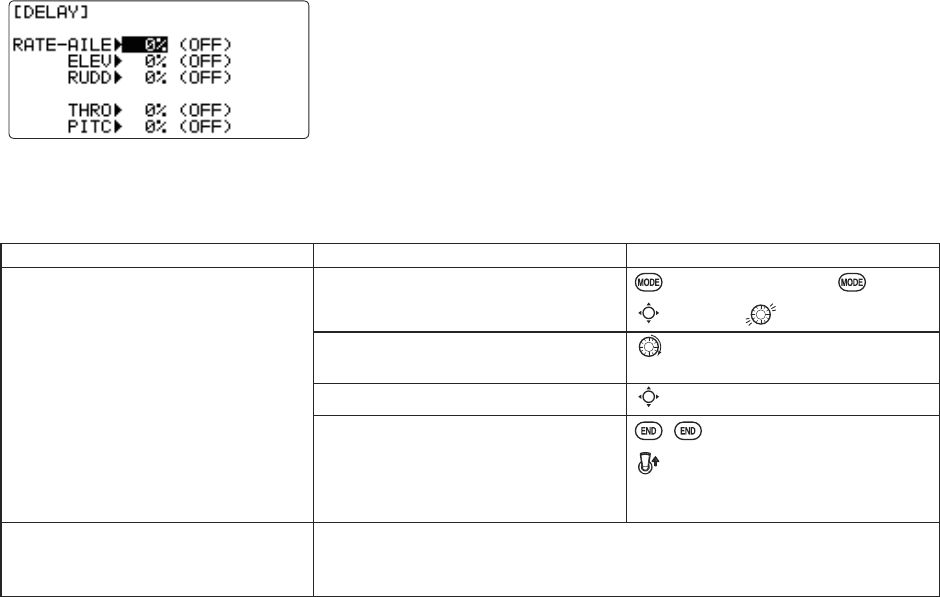
103
DELAY: The Delay function provides a smooth transition between the trim positions whenever OFFSET,REVO. MIXING, or
THROTTLE HOLD functions are turned on and off.
Adjustability:
• Separate delay times are available for aileron, elevator, rudder, throttle, and
pitch.
• With a 50% delay setting, the servo takes about a half-second to move to its
new position...quite a long time.
,QJHQHUDOGHOD\VRIDSSUR[LPDWHO\DUHVXI¿FLHQW
GOAL of EXAMPLE: STEPS: INPUTS:
Set up a delay on all channels to ease
WKH WUDQVLWLRQ IURP RQH ÀLJKW FRQGLWLRQ
to another so there are no "hard jumps."
Open the DELAY function. for 1 second. (If BASIC, again.)
C
to DELAY.
Adjust AILE response as needed. (Ex:
aileron to +8%.)
to +8%.
Repeat for other channels.
C
to ELEV. Repeat step above.
Close menus and confirm slowed
transitions. E (T10CHG) or G (T10CAG)
from NORMAL to IDL2. Check that servos
move gradually to new positions.
Where next? THR-HOLD: see p. 99.
Setting up the Idle-Ups: Throttle and Collective pitch Curves and Revo. Mixing
(THR-CURVE, PIT-CURVE, REVO. MIX) for idle-ups: see p. 101.
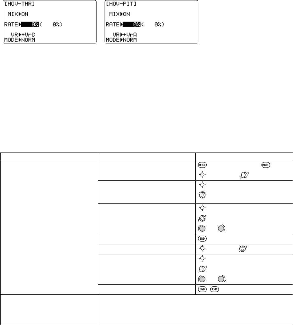
104
HOVERING ADJUSTMENTS (HOV-THR and HOV-PIT):
+RYHULQJWKURWWOHDQGKRYHULQJSLWFKDUH¿QHWXQLQJDGMXVWPHQWVIRUWKHWKURWWOHDQGFROOHFWLYHSLWFKFXUYHVLQGLYLGXDOO\
DIIHFWLQJSHUIRUPDQFHRQO\DURXQGWKHFHQWHUSRLQWDQGRQO\LQWKHQRUPDOFRQGLWLRQ7KH\DOORZLQÀLJKWWZHDNLQJRIWKH
curves for ideal setup.
Adjustability:
5RWRUVSHHGFKDQJHVFDXVHGE\WHPSKXPLGLW\DOWLWXGHRURWKHUFKDQJHVLQÀ\LQJFRQGLWLRQVDUHHDVLO\DFFRPPRGDWHG
• Both adjustments may be inhibited if not desired.
• Both adjustments may also be set to NULL, temporarily turning off the knob but maintaining the last memorized setting.
• Adjustments may be memorized and then the knobs returned to center point to use that amount of adjustment. Allows
easy use of the trimming knobs for multiple models. (Note that when memorization is repeated with the knob offset from
center, the trim value accumulates.)
• Adjustments are quickly reset to the initial value by turning the dial until the trim reads 0%, memorizing, then returning
the knob to its center position.
• Note that all functions, including these, assume the model hovers at half stick.
• Available in normal (NORMRUQRUPDOLGOHXSNORM/IDL1) condition only.
GOAL of EXAMPLE: STEPS: INPUTS:
Fine-tune hovering with the hovering
adjustments. Remember these affect
only the hovering (normal) condition.
Adjust throttle and collective pitch
curves until model hovers nicely. In
ÀLJKWDGMXVWFROOHFWLYHSLWFKDQGWKURWWOH
curves near hover point independently
with HOV-THR and HOV-PIT knobs.
6WRUHQHZVHWWLQJVDIWHUÀLJKW
Open the HOV-THR function. for 1 second. (If BASIC, again.)
C
to HOV-THR.
Optional: change which knob adjust
seach hovering curve. NULL locks in
curve in last stored position.
C
to VR.
to desired knob and direction.
Store the current dial settings prior to
selecting another model.
C
to RATE.
for one second to store.
or VR(C) to center.
Close.
Open the HOV-PIT function.
C
to HOV-PIT.
Store the current dial settings prior to
selecting another model.
C
to RATE.
for one second to store.
or VR(A) to center.
Close.
Where next? THR-HOLD: see p. 99.
Setting up the Idle-Ups: Throttle and Collective pitch Curves and Revo. Mixing
(TH-CURVE, PIT-CURVE, REVO. MIX) for idle-ups: see p. 101.
D/R,EXP: see p. 42.
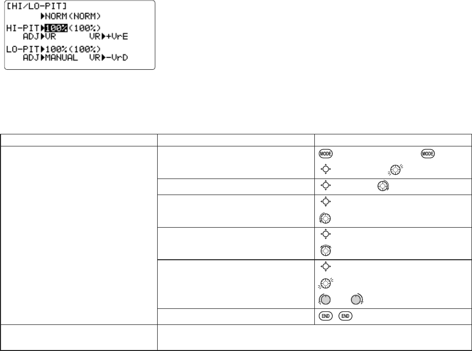
105
HIGH/LOW PITCH (HI/LO-PIT):
7KLVIXQFWLRQPD\EHXVHGWRDGMXVWWKHFXUYHVKLJKDQGORZVLGHLQGLYLGXDOO\IRUHDFKÀLJKWFRQGLWLRQQRUPDOLGOHXS
idle-up 2, idle-up 3, throttle hold).
Adjustability:
<RX PD\ GH¿QH KLJK DQG ORZ VLGH UDWH WULP NQREV WKH KLJK VLGH SLWFK WULP
FRQWUROLVGH¿QHGDVWKHULJKWVLGHOHYHUDWLQLWLDOVHWWLQJ
• The conditions are activated in the CONDITION SELECT function (p.100).
• Both adjustments may be set to MANUAL, temporarily turning off the knob.
• Adjustments may be memorized and then return the knobs to center point to
use that amount of adjustment. Allows easy use of the trimming knobs for
multiple models.
GOAL of EXAMPLE: STEPS: INPUTS:
Set up a high pitch curve in the idle-up
1 condition.
6WRUHQHZVHWWLQJVDIWHUÀLJKW
Open the HI/LO-PIT function. for 1 second. (If BASIC, again.)
C
to HI/LO-PIT.
Select the idle-up 1 condition.
C
to NORM. to IDL1.
Set the rate. (Ex: 80%)
C
to HI-PIT.
to 80%.
Optional: change which knob adjusts
high pitch curve.
C
to VR.
to desired knob and direction.
Store the current dial settings prior to
selecting another model.
C
to HI-PIT.
for one second to store.
or VR(E) to center.
Close.
Where next? PIT-CURVE: see p. 100.
HOV-PIT: see p. 104.
106
*<526DQG*29(512568VLQJHOHFWURQLFVWRWDNHVRPHRIWKHFRPSOH[LW\RXWRIVHWXSVDQGÀLJKW
What is a gyro? A gyroscope is an electronic unit that senses motion and corrects for it. For example, if the wind blows
\RXUKHOLFRSWHU¶VWDLOWRWKHOHIWDJ\URZLOOVHQVHWKDWPRWLRQDQGFRQ¿UPWKDWQRLQSXWZDVJLYHQDQGZLOOFRUUHFWIRULW
How does it help in helicopter setup? A good gyro will totally eliminate the need for revo. mixing. The gyro will sense and
correct the unwanted motion for you, so you don’t have to spend time to get a complex curve operating properly.
Gyro sensor kinds: There are many different kinds of gyros. Early gyros were mechanical, with a spinning drum similar to
a child’s gyroscope toy. The next generation utilized a special type of crystal, called piezoelectric, which sensed the motion
DQGSURYLGHGDQHOHFWULFDOSXOVH7KH¿QHVWJ\URVDWWKHWLPHRIWKLVZULWLQJDUH600WHFKQRORJ\7KHVHVLOLFRQHPLFUR
machines, or computer chips, sense the motion. SMM is far more accurate and less susceptible to inaccuracies caused by
temperature changes, etc.
Types of gyro responses:
• Normal: sense motion and dampen it (if the gyro rotates off course for 2 seconds, it corrects for 2 seconds).
+HDGLQJKROG$9&6 FDOFXODWH WKH DQJOH RI URWDWLRQ E\ WUDFNLQJ WKH WLPHUDWH RI FKDQJH DQG WKHQ SURYLGH FRUUHFWLRQ
until the same rotation is achieved.
• Stick priority: a feature on most high-end gyros. The more input given on the channel the gyro controls, the less sensitive
the gain is automatically. This way, if you give a large input for a stall turn, for example, the gyro turns itself off and
GRHVQRW¿JKWWKHVWDOOWXUQ$V\RXHDVHRIIWKHUXGGHUWKHJDLQLQFUHDVHVDJDLQPLQLPL]LQJWDLOZDJDQGNHHSLQJWKH
model straight. (If your gyro does not include stick priority, you can manually create it. Please see www.futaba-rc.com\
faq\.)
Choosing the right gyro for your skills, your helicopter, and your budget:
• Mechanical: some are still available. They are very challenging to set up and not as reliable as piezo or SMM.
• Non-Heading-Hold Piezo: these are now inexpensive gyros that are reliable and easy to set up. Some have dual rates and
UHPRWHJDLQFRQWUROWRDGMXVWVHQVLWLYLW\LQÀLJKW/DFNKHDGLQJKROGFDSDELOLWLHVIRUSUHFLVLRQÀ\LQJ
• Heading-Hold Piezo: Until recently, the cream of the crop. Expensive, and more complex to set up. Adds GPS-like
KHDGLQJUHFRJQLWLRQ([KLELWVPLQRUGLI¿FXOWLHVZLWKWHPSHUDWXUHGULIWSRVLWLRQVHWWLQJYDU\LQJZLWKXQLW¶VWHPSHUDWXUH
• Heading-Hold SMM: 21st Century gyro technology. Computer chip technology. Expensive, easier set up, higher
GXUDELOLW\6LJQL¿FDQWGHFUHDVHLQWHPSHUDWXUHVHQVLWLYLW\0DQ\LQFOXGHIUDPHUDWHVHWWLQJVWRDOORZIDVWHUUHVSRQVHZKHQ
using specialized digital servos. Examples:
• GY401: Simpler set up. Ideal for learning aerobatics through 3D.
• GY502: Better centering than 401 for more advanced aerobatics. Ideal through Class III competition.
• GY611: Exceptional center. Extremely fast response time. Requires specialized servo.
GYROVLPSOL¿HVDGMXVWLQJVHOHFWLQJWKHJ\URVHQVLWLYLW\DQGFDQSURYLGHPRUHWKDQJ\URJDLQVHWWLQJV7KHKLJKHUWKH
gain, the more correction the gyro provides and the “softer” or less responsive the helicopter feels.) This function makes
WKHEHVWSRVVLEOHXVHRIWKHLQÀLJKWDGMXVWDEOHJDLQRIPRVWJ\URV
Adjustability:
• Plug the gyro’s sensitivity adjustment to channel 5 of the receiver. (not assignable)
•STDDQG$9&6+HDGLQJKROGGYVHWXSW\SHVDYDLODEOHWRVLPSOLI\DGMXVWPHQWVIRU$9&6+HDGLQJKROGJ\URV
• Full switch assignability or may select Cond. option.
•Cond. option provides separate gyro settings, one for each condition, automatically selected with the condition. Allows
FKDQJHVLQJDLQWRPHHWWKHVSHFL¿FQHHGVRIHDFKÀLJKWFRQGLWLRQ
• Each gyro setting may be set from 0 to +100 (NOR100% to AVC100%) gain, equating to ATV settings of -100% to +100%.
'XDOPRGHJ\URVKHDGLQJKROG$9&6DQGQRUPDODUHHDVLO\WULJJHUHGWRHDFKPRGHE\FKDQJLQJWKHJ\URVHWWLQJ¶VVLJQ
Negative settings trigger normal mode; positive settings are AVCS mode.
• Larger percentages indicate more gain, or gyro responsiveness.
• Tail wagging or shaking indicates excessive gain settings. Turn down gyro setting until wag stops.
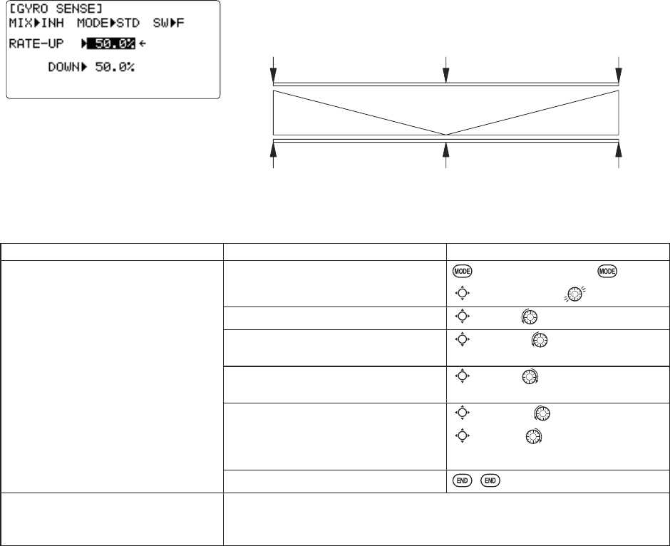
107
Gain Example for AVCS/Heading-hold Gyros (GY)
GOAL of EXAMPLE: STEPS: INPUTS:
6HWXSDKHDGLQJKROG$9&6J\URZLWK
KHDGLQJKROG$9&6 VHWWLQJ LQ LGOHXSV
1 and 2 and normal mode setting in idle-
up3 and normal.
Open and activate the GYRO SENSE
function.
for 1 second. (If BASIC, again.)
C
to GYRO SENSE.
Activate the function.
C
to MIX. to ACT.
Optional: change gyro type to Heading-
hold (GY).
C
to MODE. to GY.
Optional: change switch assignment.
Ex: select Cond.
C
to SW. to Cond.
Adjust gyro rates as needed.
(Ex: NORM,IDL3 to NOR 50%.IDL1 and 2
to AVC 50% as starting points.)
C
to NORM. to NOR 50%.
C
to IDL1. to AVC 50%.
Repeat.
Close the function.
Where next? GOVERNOR: see p. 108.
D/R,EXP: see p. 42.
DELAY: see p. 103.
50%0% +100%
"Heading Hold Mode"
"Normal Mode"
CVA%001%0RON%001
GY
STD
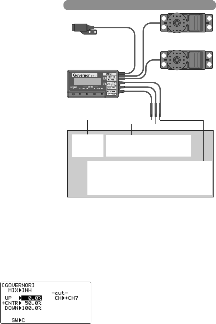
108
GOVERNORS:
What is a governor? A governor is made up of a set of sensors which read the RPM of the helicopter’s head, and a
control unit that automatically adjusts the throttle setting to maintain a constant head speed regardless of changes in pitch
of blades, weather conditions, etc. Governors are extremely popular in competition helicopters due to the consistency
provided.
How does it help in helicopter setup? The governor eliminates the need to spend large amounts of time setting up throttle
curves, as it automatically adjusts the engine’s RPM to maintain the desired head speed.
GOVERNOR: The Governor mixing function is used to adjust the GV-1 (Governor) speed settings (rS1, rS2, rS3) from the
transmitter. (If you are using a different governor, follow the manufacturer's instructions.)
Adjustability:
2QRIIPD\EHVHSDUDWHIURPVSHHGVZLWFKLQJE\SOXJJLQJJRYHUQRURQRIILQWR
ch8 and changing CUT-CH setting.
,I XVLQJ VHSDUDWH RQRII VZLWFK DVVLJQPHQW LV WRWDOO\ DGMXVWDEOH %H FDUHIXO
not to assign governor off to a condition switch if you want the governor to
function in that condition.
6SHHGVZLWFKLQJDQGJRYHUQRU212))PD\EHWRJHWKHUXVLQJRQHVZLWFKRU
212))VZLWFKLQJPD\EHSHUIRUPHGXVLQJDQLQGHSHQGHQWVZLWFKFKDQQHO
:KHQVSHHGVHWWLQJFRQWUROXVHV&+DQGVHSDUDWH212))VZLWFKLVQRWXVHG
CH8 can be used for other functions.
,QÀLJKWDGMXVWPHQWRIWKHKHDGVSHHGIRUHDV\DGMXVWPHQWGXULQJWXQLQJPD\
be created using an additional channel and a programmable mix. See www.
futaba-rc.com\faq\ for details.
GV-1 connections
Magnetic sensor
Throttle servo
Control amp
Mixture servo
Connected only when
fuel mixture function
used.
Throttle
channel
Speed setting channel
Connected when speed set from
transmitter
Governor ON/OFF / Mixture trim channel
Connected when the governor is turned on and off
from transmitter and when mixture trim function is
used, or when mixture curve data is sent from transmit-
ter to governor
Receiver
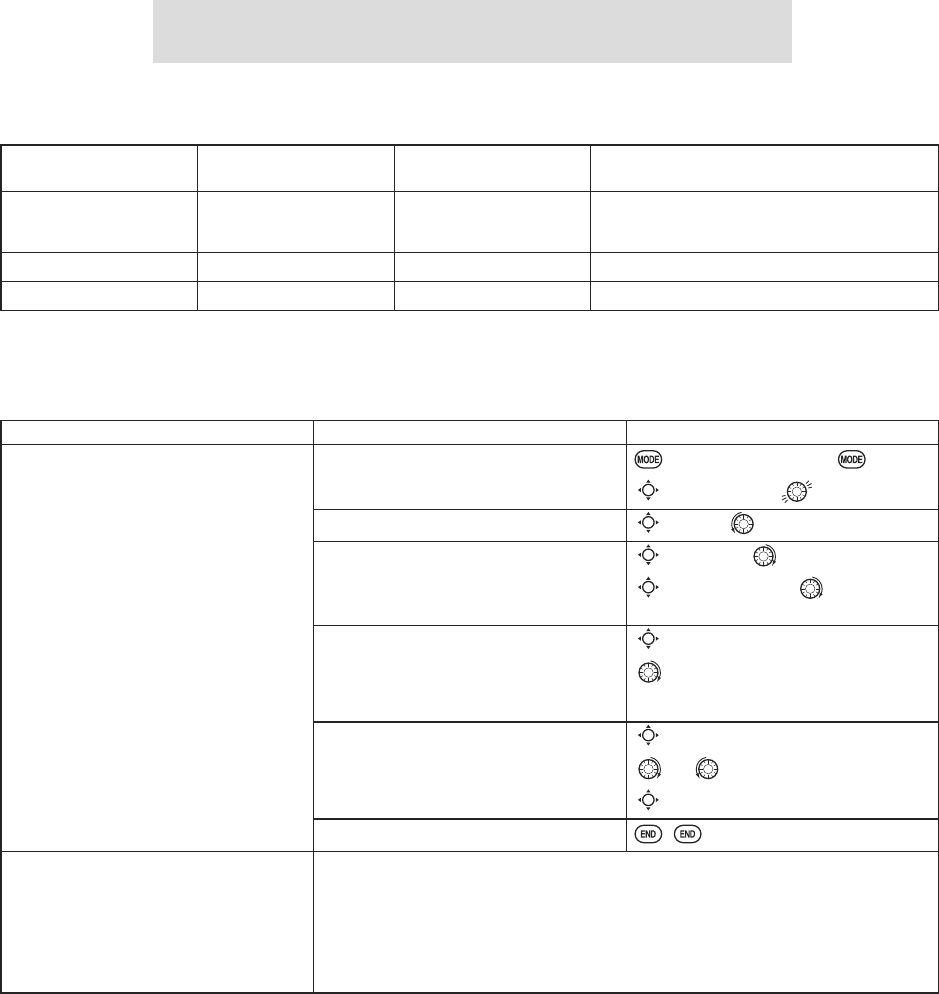
109
The GV-1 controls throttle when it is active, so the throttle will not obey any FailSafe settings preset for throttle in the
WUDQVPLWWHU$OZD\VVHWWKH)DLO6DIHVHWWLQJIRUWKH*9¶VRQRIIFKDQQHOWR2))7KLVZD\WKHJRYHUQRULVVKXWRII
and the throttle obeys the FailSafe throttle commands.
Expert Tip: Mounting the GV-1 to the counter gear instead of the fan
GUDPDWLFDOO\VLPSOL¿HVLQVWDOODWLRQLQPDQ\PRGHOV
Setting example: :KHQVSHHGDQG212))DUHXVLQJRQHVZLWFK
Governor Speed Switch Position
(Switch C or Cond.) Rate (%) Adjustment from Tx.
RS1: OFF UP or NORM 0 Use up to 0%.
(Governor speed display reads “off”.)
RS2: 1400 CNTR or IDL1 50 Speed adjusted by raising and lowering rate.
RS3: 1700 DOWN or IDL2 100 Speed adjusted by lowering rate.
*The relationship of the governor speed setting rS1~rS3 and the switch positions conforms to the table above.
*In throttle hold, always check that the governor is off.
*If the speed value rises when the cut switch is activated, reverse the “DIR” setting from UP to DOWN or vice versa.
GOAL of EXAMPLE: STEPS: INPUTS:
Set up a GV1 governor to use
both channels into the receiver
and switch between the governor
settings automatically when changing
conditions. Consider setting the battery
Fail Safe settings and other helpful
functions on the GV-1 itself.
Open and activate the GOVERNOR
function.
for 1 second. (If BASIC, again.)
C
to GOVERNOR.
Activate the function.
C
to MIX. to ACT.
Optional: change cut-off channel
to channel 8 and assign switch and
direction for on/off (channel 8).
C
to cut-CH to +CH8.
C
to cut-SW. to desired
SWITCH.
Optional: change switch assignment to
select governor settings.
Ex: select switch that selects the
conditions.
C
to SW.
to Cond.
Adjust governor speed settings per
switch position or condition as needed.
(Ex: defaults are fine.) Allows head
speed adjustment from transmitter.
C
to each Cond position.
or as needed.
C
to next Cond position. Repeat.
Close the function.
Where next? GYRO: see p. 107.
Adjust FailSafe (F/S) settings (p. 50).
$GMXVWLGOHXSFROOHFWLYHSLWFKFXUYHIRUVDPHUDWHVRIFOLPEXSULJKWLQYHUWHG
See p. 101.
$GMXVW HOHYDWRUDLOHURQ UHVSRQVH WR ILW \RXU IO\LQJ VW\OH VHH D/R,EXP and END
POINTSWASH AFR: p. 42, 39, 95.
110
GLOSSARY
'&RPPRQQDPHIRUFHUWDLQW\SHVRIDHUREDWLFPDQHXYHUV$LUFUDIWÀ\LQJEHORZWKHPRGHO¶VVWDOOVSHHGVXFKDVWRUTXH
rolls. Helicopters: combining 2 or more maneuvers, such as rolling loop.
4.8V: 4.8 volt battery pack, made of 4 Ni-Cd 1.2V cells. See Accessories.
5-cell: 6.0 volt battery pack, made of 4 alkaline cells or 5 Ni-Cd cells. See Accessories.
6V (6Volt): battery pack, made of 4 alkaline cells or 5 Ni-Cd cells. See Accessories.
ACCELERATION: a delay mix which richens engine mixture and then returns to normal to compensate for abrupt throttle
changes. See THROTTLE-NEEDLE. ............................................................................................................................................ 65
Accessories: additional optional items which may be used with your 10CG. ..................................................................... 10
ACRO: model type designed for use with powered aircraft. Selected in the MODEL submenu under TYPE. ........................... 34
ACRO vs GLID comparison. .................................................................................................................................................... 34
ACT. Active. Make a feature able to be utilized. Opposite of INH. Only visible in certain features.
Adjustable Function Rate: see SWASH AFR.
$GMXVWDEOH6HUYR7UDYHO$67DVSHFL¿FW\SHRIHQGSRLQWDGMXVWPHQW6HHEND POINT.
Adjustable Travel Limited (ATL): End point adjustment for low end only, for throttle channel. See ATL.
$GMXVWDEOH7UDYHO9ROXPH$79DQROGHUOHVVVSHFL¿FWHUPIRUHQGSRLQWDGMXVWPHQW6HHEND POINT.
ADVANCEPHQXV 6SHFL¿F PHQXV IRU HDFK PRGHO W\SH ZKLFKDOORZWKHPRGHOHUWRDFFHVVDQGSURJUDP WKH UDGLR¶V PRUH
advanced features.
AFR: Adjustable function rate. Used only in HELI model types with CCPM heads. See SWASH AFR.
AILE-2: second aileron servo assignment. See Twin aileron servos.
AILE1/2/3/4: Designation for the individual servos that are being commanded by the aileron command. Ex: when using
ailevators, the two elevator servos are also acting as ailerons 3 and 4 (unless you set their values to 0). See Twin aileron
servos and Twin elevator servos.
AILE/RUDD (
GLID): You can select a pre-programed mix which is used to mix the rudders with aileron operation or the
DLOHURQVZLWKUXGGHURSHUDWLRQ$LOHURQWRUXGGHUPL[$,/(ĺ58''DXWRPDWLFDOO\FUHDWHVDFRRUGLQDWHGWXUQ5XGGHU
WRDLOHURQPL[58''ĺ$,/(XVHGWRFRXQWHUUDFWXQGHVLUDEOHUROOUROOFRXSOLQJ WKDW KDSSHQV ZLWK UXGGHU LQSXW
especially in knife-edge. ...................................................................................................................................................... 81
Aileron: surface that controls the roll of the model. Also called cyclic roll on a helicopter.
$LOHURQWRÀDS PL[LQJ 0L[LQJ XVHG WR FUHDWH IXOOVSDQ DLOHURQ DFWLRQ 1RW D SUHSURJUDPPHG PL[ 6HH Programmable
mix. This is the default setup of one mix in GLID.
Aileron-to-rudder mix: Mixing that automatically creates a “coordinated turn”. Not a preprogrammed mix. See
Programmable mix. This is the default setup of one curve mix in HELIGLID.
Aileron Differential: Decreased down aileron travel when compared to up aileron travel. Minimizes “dragging” the low
wing and creates more axial rolls. See Twin aileron servos. .............................................................................................. 51
Ailevator: two elevators on separate channels, also capable of acting as additional ailerons. See Twin elevator servos.
AILEVATORS: (ACRO) Twin elevator servos plugged into separate channels, used to control elevator with the option to also
act as ailerons in conjunction with the primary ailerons. ..................................................................................................... 56
Airbrake-to-elevator mixing: (GLID) Applies up or down elevator when airbrakes are deployed, correcting for any pitch
change from the added drag. Not a preprogrammed mix. See Programmable mix.
Airbrake: (GLID/HDGLQJHGJHÀDSVRQJOLGHUVFRQWUROOHGE\CHANNEL 3 (NORMALLY THROTTLE) STICK.
AIRBRAKE: (ACRO&RPELQHVHOHYDWRUÀDSDQGRSWLRQDOO\VSRLOHUVWRVXGGHQO\VORZWKHPRGHOIRUVSRWODQGLQJV0D\EH
111
triggered by THROTTLE STICK POSITION. For similar glider programming, see BUTTERFLY. ...................................... 63
$0$$FDGHP\RI0RGHO$HURQDXWLFV1RQSUR¿WRUJDQL]DWLRQJRYHUQLQJPRGHODLUFUDIWÀLJKWLQWKH86...................... 5
AST: Adjustable Servo Travel. See END POINT.
ATL: Adjustable Travel Limited. Standard type of trim used for throttle, where the trim is effective only in the idle portion
of the THROTTLE STICK POSITION. Normal trims affect the entire travel of the servo (ex: elevator trims), but ATL
trims only the low end of the throttle movement, allowing throttle idle adjustments that donit over-drive the servo at full
throttle. ................................................................................................................................................................................. 38
ATV: Older, less clear terminology for end point adjustment. See END POINT.
Autorotation: The ability of a helicopter to land safely without engine power, using the stored energy in the bladeis rotation
WRSURGXFHOLIWIRUÀDULQJ
AUX-CH: Auxiliary channel setup. Used to assign which KNOBSSWITCHESSLIDERS control channels 5-9. Includes
CH9 servo reverse. Also allows assignment of a channel to mixing only (assigned as NULL), with no primary control. .... 46
Backup battery: battery used to protect data storage in case of removal of master transmitter battery. In most Futaba radios,
including the 10CG, EEPROM data storage is used, so no backup battery is used or needed.
BACKUP ERROR: transmitter's hard-coded memory has been lost. Send for service immediately. ....................................... 24
Base-Loaded antenna: also called Whip antenna. Aftermarket equipment not approved by Futaba.
Basic model setups: guidelines to setting up the most basic models of each type. ........................ ACRO 27 GLID 76 HELI 90
BASICPHQXV6SHFL¿FPHQXVZLWKPRVWFRPPRQO\XVHGIHDWXUHVIRUHDFKPRGHOW\SH .............. ACRO 30 GLID 78 HELI 93
Battery care and charging. (Charging the Ni-Cd batteries) ................................................................................................. 15
Battery FailSafe: determines how the receiver indicates an airborne pack low-battery warning. Defaults: 56% throttle,
requires throttle to idle to override. To adjust the warning point, set a THROTTLE STICK POSITION in F/S. .............. 50
BEEP: tone emitted by transmitter to signify a variety of situations. See Error messages.
Binding: friction in a joint exceeding the movement of the linkage. Sticking or inability to continue movement. The servo
FRQWLQXHVWRDWWHPSWWRPRYHWKHVXUIDFHEH\RQGLWVSRZHUFDSDELOLWLHVUDSLGO\GUDLQLQJEDWWHU\SRZHUDVLWFRQWLQXHVWR
struggle.
%UDNHÀDSPL[LQJGLID7KUHHPL[HVEUDNHÀDSWRHOHYDWRUWRDLOHURQDQGWRVSHHGÀDSVFRPSHQVDWHIRUXQZDQWHG
reaction to lowering the brake flap, 2) increase brake flap area by including the flaperons, and 3) add lift to increase
maneuverability. Not a preprogrammed mix. See Programmable mix.
Buddy Box: see Trainer box.
BUTTERFLY: (GLID) [also called crow, AIRBRAKE(ACRO@$FWLYDWHV XS ÀDSHURQV DQG GRZQ ÀDSV IRU JOLGLQJ VSHHG FRQWURO
without spoilers or airbrakes. Note: More adjustable programming is available in ACRO,AIRBRAKE. ................................ 63
CAMBER FLAP (GLIDDVVLJQVWKHSULPDU\ÀDSFRQWUROWRDOORZWULPPLQJLQÀLJKWRIWKHÀDSDFWLRQ7KHXSGRZQWUDYHORI
HDFKÀDSFDQEHDGMXVWHGLQGHSHQGHQWO\$OVRWKHFHQWHUSRVLWLRQRIÀDSVHUYRFDQEHRIIVHW........................................... 86
CAMBER MIX (GLIDDGMXVWVWKHPL[LQJUDWHRIFDPEHURSHUDWLRQZKLFKRSHUDWHVWKHZLQJFDPEHUDLOHURQVDQGÀDSVLQ
WKHQHJDWLYHDQGSRVLWLYHGLUHFWLRQV7KHDLOHURQÀDSDQGHOHYDWRUUDWHVFDQDOVREHDGMXVWHGLQGHSHQGHQWO\DQGDWWLWXGH
changes caused by camber operation can be corrected. ....................................................................................................... 85
CAMPac2SWLRQDOH[WHQGHGGDWDVWRUDJHPRGXOH)XWDEDVWRFN'3....................................................... 10
CCPM: Cyclic (pitch and roll) Collective Pitch Mixing. Multiple servos work in unison on the helicopteris head to create
one or more of the control functions. Ex: 3 servos set at 120 degrees operate the entire head. The 2 forward servos work
together to rotate both the blade's pitch and the roll cyclic (aileron) in a HR3 head type. See MODEL TYPE,HELI.
CH5&6: setting in AILE-2 that allows the second aileron servo to be in channel 5. See Twin aileron servos.
CH6 or 7: default setting in AILE-2. Second aileron servo is in channel 6 or 7 depending on function used. See Twin aileron
112
servos.
&KDQQHOVZLWFKVHOHFWLRQDQGGLUHFWLRQFRQWURO6HHAUX-CH. ...................................................................................... 46
Channel delay: see THROTTLE DELAY (ACRO) and DELAY(HELI).
Charge: to increase the electrical energy, measured as voltage, available in a battery pack. See Battery care and charging.
Condition: (HELIVHSDUDWHÀLJKWVHWXSWKDWKDVVLJQL¿FDQWDGMXVWDELOLW\VHSDUDWHIURPWKHEDVLFPRGHOVHWXS6HHIDLEUP 1, 2,
3 and THROTTLE HOLD.
Contact information, North American Service Center. .......................................................................................................... 3
Copy model: see MODEL COPY.
Crow: see BUTTERFLY (GLID) and AIRBRAKE (ACRO).
Cursor: See SELECT BUTTONS.
Curve Mix: a mix that does not have the same reaction at all points along the master channel. See Programmable mix.
Cyclic: horizontal controls on a helicopter. Cyclic pitch is typically called elevator. Cyclic roll is typically called aileron.
'DWDUHVHWHUDVHDOOGDWDLQDVSHFL¿FPRGHO6HHRESET.
DELAY: (HELI) slows the servo’s reaction time when changing from one condition to another. Eases any “jumps” in transition
from one pitch setting to another, etc. Also see THROTTLE DELAY, p. 59 (ACRO). ................................................................ 103
Delta peak charger: common name for a specialized charger designed and required to properly peak charge both NiMH
DQG1L&GEDWWHULHVDFWXDOO\FDOOHGD=HUR'HOWD93HDN&KDUJHU6HHBattery Care and Charging.
Dial: transmitter’s rotary control and button used in various ways during programming. .................................................. 11
Dial mix: mix that uses a knob or slider as the master control, moving the slave servo based upon the movement of the
knob or slider. See Prog. mix.
Differential: uneven movement in each direction of a control surface. Usually used when discussing ailerons or when
describing an undesirable unevenness in movement of other controls. See Twin aileron servos.
'LRGHDQHOHFWURQLFGHYLFHZKLFKRQO\DOORZVFXUUHQWWRÀRZRQHGLUHFWLRQ8VHGWRSURWHFWUDGLRDJDLQVWSRZHUVXUJHDQG
reversed polarity during charging. ....................................................................................................................................... 15
DIR-SW: switches that change between the 4 separate directions of snaps available. See SNAP ROLL.
Discharge: to deplete the electrical energy in a battery pack, usually to its lowest safe voltage, for storage or as a part of
regular maintenance. See Battery care and charging.
DP16K: see CAMPac.
Dual aileron servos: (ACROGLIDDPRGHOXVLQJVHUYRVRQVHSDUDWHFKDQQHOVWRRSHUDWHDLOHURQV0D\LQFOXGHÀDSHURQ
action or aileron differential. See Twin aileron servos. ....................................................................................................... 51
Dual elevator servos: (ACROGLID) a model using 2 servos on 2 separate channels to operate elevators. Includes elevon,
V-tail, ailevator. See Twin elevator servos. ......................................................................................................................... 56
Dual rates (D/R,EXPUHGXFHLQFUHDVHWKHVHUYRWUDYHOE\ÀLSSLQJDVZLWFKRUE\VWLFNSRVLWLRQ8VHGWRPDNHPRGHOPRUH
FRPIRUWDEOHWRÀ\LQGLIIHUHQWPDQHXYHUV&*VXSSRUWVWULSOHUDWHVE\VLPSO\DVVLJQLQJGXDOUDWHVWRSRVLWLRQVZLWFKHV
Includes exponential function, see EXP. ................................................................................................................................ 42
Elapsed Time Counter reset: see TIMER. ............................................................................................................................... 45
ELE1/2/3/4: designation for the individual servos that are being commanded by the elevator command. Ex: when using
elevon, the two wing servos are acting as elevators 1 and 2. See Twin elevator servos.
Elevator: surface which controls the model’s rate of climb or descent. Also called cyclic pitch on helicopters.
Elevator-to-airbrake mix: (GLID) used to allow the model to loop even tighter on elevator input by having airbrakes work with
elevators. Not a preprogrammed mix. See Programmable mix. This is the default programming for one curve mix in GLID.
113
(OHYDWRUWRÀDSPL[ ACROGLID8VHG WR DSSO\ÀDSV DORQJ ZLWKHOHYDWRUV WR LQFUHDVHOLIW DOORZLQJ PRGHOHUWR À\ DW
slower speeds, make tighter loops or turns, etc. Not a preprogrammed mix. See Programmable mix. This is the default
setting of one mix in ACRO and GLID.
Elevator-to-pitch mix: (HELI) used to adjust pitch to counter the loss of angle of attack when elevator input is given. Not a
preprogrammed mix. See Programmable mix. This is the default setting of one mix in HELI.
ELEVON À\LQJ ZLQJ FRQ¿JXUDWLRQ ZLWK VHUYRV ZRUNLQJ WRJHWKHU WR FUHDWH ERWK DLOHURQ DQG HOHYDWRU DFWLRQ 6HH 7ZLQ
elevator servos. .................................................................................................................................................................... 56
Elevons: two surfaces, one on each wing, which work as both ailerons and elevators. See ELEVON.
END BUTTON: control button used during programming to return to previous menu or close menu altogether.
END POINT: often abbreviated EPA. Adjusts the total travel in each direction of proportional servos regardless of their
control assignment. Ex: adjustment to AIL channel will adjust only the servo plugged into channel 1 even if being used
DVRQHRIWZRÀDSHURQVRUHOHYRQV1RWH(QGSRLQWLVQRWDQDEVROXWHPL[LQJFDQVWLOOGULYHWKHVHUYRIDUWKHUWKDQWKLV
setting. .................................................................................................................................................................................. 39
Engine cut: see THROTTLE-CUT.
EPA: see END POINT.
(UURUPHVVDJHVZDUQLQJVFDXWLRQVSURYLGHGE\WKHUDGLRZKHQSRWHQWLDOSUREOHPVPD\H[LVW ........................................ 24
Exponential (D/R,EXP): adjustment to the relationship of STICK MOVEMENT to servo movement, typically used to soften
overly sensitive models around center. ................................................................................................................................ 42
FASST: Futaba Advanced Spread Spectrum Technology
FailSafe (F/S): sets servo positions when interference is encountered or signal is lost. Also includes Battery FailSafe
settings. ................................................................................................................................................................................ 50
FLAP1/2/3/4GHVLJQDWLRQIRUWKHLQGLYLGXDOVHUYRVWKDWDUHEHLQJFRPPDQGHGE\WKHÀDSFRPPDQGV([ZKHQDFWLQJDV
ÀDSHURQVWKHWZRDLOHURQVHUYRVDUHDLOHURQVDQGDQG DOVRÀDSV DQGXQOHVV\RXVHWWKHLUYDOXHVWRWKHQ WKH\
PRYHRQO\DVDLOHURQQRPDWWHUZKDWÀDSFRPPDQGVDUHJLYHQ6HHTwin aileron servos and Twin elevator servos.
Flap-to-aileron mix: (ACROGLID) used to create full span flap reaction in flight. Not a preprogrammed mix. See
Programmable mix. This is the default setup of one mix in GLID.
Flap-to-elevator mix: (ACROGLIDXVHGWRFRXQWHUDFWXQZDQWHGFKDQJHVLQSLWFKZKHQÀDSVDUHGHSOR\HG1RWD
preprogrammed mix. See Programmable mix. This is the default setup of one mix in ACRO and GLID.
FLAPERONRQHVHUYRRQHDFKDLOHURQSOXJJHGLQWRFKDQQHOVDQGZKLFKRSHUDWHERWKDVDLOHURQVDQGDVÀDSV6HHTwin
aileron servos. ...................................................................................................................................................................... 51
FLAP-TRIM$GMXVWPHQW RI FHQWUDO SRVLWLRQ RI ÀDSHURQV GHIDXOW DVVLJQHG WR &+$11(/ KNOB. May also be used as
SULPDU\RURQO\FRQWURORIÀDSHURQVDFWLQJDVÀDSVRURWKHUPL[HVPD\EHVHWXS6HHTwin aileron servos. .................. 53
Fuel mixture control: (ACROHELI) see THROTTLE-NEEDLE.
FUNC: function mode of TRAINER, allows student radio to use the computer programming for that channel in the master
UDGLR ([ DOORZV D VWXGHQW ZLWK D FKDQQHO WUDQVPLWWHU WR À\ DQ VHUYR DHUREDWLF SODQH RU D VHUYR KHOLFRSWHU 6HH
TRAINER.
Gain: the responsiveness or amount of control given the gyro. On a high gain, the gyro is very active and overrides nearly
all other actions. Too high a gain may result in “wagging” at the surface as the gyro over-corrects repeatedly in each
direction. See GYRO SENS.
Gear doors: covers for retractable landing gear, may be operated separately from landing gear on some models. ............ 74
GLID: model type, glider. ...................................................................................................................................................... 75
Governor: electronic device that reads the speed at which the head is spinning, and adjusts the throttle servo to maintain
114
the desired speed.
GOVERNOR: (HELI) programming which eases the setup of the GV-1 governor. ................................................................. 106
*9SDUWQXPEHUQDPHIRU)XWDEDLVHOHFWURQLFJRYHUQRU6HHGyros and Governors and GOVERNOR for details.
Gyro, gyroscope: equipment that senses change in direction and provides input to compensate for that change. For
description of aircraft use, see p. 66. For description of types, and helicopter use, see GYRO SENS.
GYRO SENS (ACROHELI): gyro sensitivity programming designed to ease the setup and use of gyroscopes on model
airplanes and helicopters. Manual pages include extensive descriptions of gyro types. ............................................. 73, 106
Gyros and Governors ......................................................................................................................................................... 106
+HDGLQJKROGJ\URJ\URWKDWVSHFL¿FDOO\PHDVXUHVWKHXQZDQWHGGHÀHFWLRQDQJOHDQGFRPSHQVDWHVXQWLODFRUUHVSRQGLQJ
angle has been returned. See Gyros and Governors.
HELI: model type, rotary wing. See MODEL TYPE.
+HOLFRSWHUUDGLRWUDQVPLWWHUWKDWLQFOXGHVKHOLFRSWHUIULHQGO\VZLWFKDQGFRQWUROOD\RXWDQGVXI¿FLHQWSURJUDPPLQJWRDW
least support a 5-channel helicopter. The 10CAG and 10CHG radios both contain all needed programming. The 10CHG
has a more heli-friendly layout (through switch positioning and no ratchet on throttle for easier hovering)
HI/LO-PIT (HELIPD\EHXVHGWRDGMXVWSLWFKFXUYHVKLJKDQGORZVLGHLQÀLJKW ............................................................. 105
High Rate: See D/R,EXP.
Hover: to maintain a stationary position relative to a point on the ground.
HOVERING PITCH: see Hovering setups.
HOVERING THROTTLE: see Hovering setups.
+RYHULQJVHWXSVLQÀLJKWDGMXVWPHQWVWRSLWFKDQGWKURWWOHFXUYHVDURXQGFHQWHUTHROTTLE STICK position (the ideal
hovering point). .................................................................................................................................................................. 104
Idle management: varying settings and control of the modelis idle. Ex: using IDLE-DOWN to lower engine's idle point for
landings and certain maneuvers; using THR-CUT function to safely and accurately shut the engine off as needed without
requiring constant adjustment of throttle trims. ................................................................................................................... 40
IDLE-DOWN:: offset mix that slows the engineis idle point (decreasing the amount of travel of the throttle servo when at low
THROTTLE STICK POSITION). Typically used to keep the model sitting still on the runway prior to take off, for slow
aerobatic maneuvers such as spins, and for landings. See Idle management. ..................................................................... 40
IDLE-UPVHSDUDWHFRQGLWLRQFUHDWHGWRDOORZLQYHUWHGDQGRWKHUW\SHVRIÀLJKWZLWKDKHOLFRSWHUQRWHDVLO\DFKLHYHGLQWKH
normal condition. Note: the idle-ups are activated by activating their throttle curves. Also note that OFFSET is available to
create separate trims within each condition. ...................................................................................................................... 101
,QÀLJKWQHHGOHFRQWUROVHHTHROTTLE-NEEDLE.
INHPDNHVDIHDWXUHLQDFWLYHXQDEOHWREHXVHG:KHQDIXQFWLRQLVLQKLELWHGLWFDQQRWEHXVHGHYHQLIWKHDVVLJQHGVZLWFK
LV217XUQVRIIIXQFWLRQDOLW\ZLWKRXWORVLQJDQ\VHWWLQJV2QO\YLVLEOHLQVSHFL¿FIHDWXUHV
Inhibit: see INH.
Installation: radio installation and setup. ............................................................................................................................. 18
,QYHUWHGWRÀ\DPRGHOXSVLGHGRZQ
,QYHUWHGÀLJKWFRQWUROSURJUDPPLQJQRWDYDLODEOHLQWKH&*0RVWPRGHOHUVQRORQJHUXVHWKLVLFUXWFKLWRÀ\LQYHUWHG
instead learning to recognize the modelis behaviors when inverted and compensate appropriately.
Kill switch: (1) throttle cut switch to close carburetor (see THR-CUT, p. 40). (2) gasoline ignition engine kill switch which
removes spark to the plugs to stop the engine. .................................................................................................................... 74
115
Launch setting: (GLID) see START-OFS.
Linear Mix: a mix that maintains the same relationship of master to slave throughout the whole range. Ex: a mix from
RQHÀDSVHUYRWRDQRWKHUÀDSVHUYRDWFDXVHVWKHQGVHUYRWRIROORZWKH¿UVWVHUYR¶VPRYHPHQWH[DFWO\WKURXJKDOO
points of travel. See Programmable mix.
LINK: mixing function that allows multiple mixes to work in conjunction. See Programmable mix.
Linear: linear, directly proportional. See AIRBRAKE.
LOGIC SW: can be assigned to the following functions: THR-CUT,IDLE DOWN,AUX-CH,TIMER,PROG. MIX,AIRBRAKE,ELEV-
FLAP, and AILE-FLAP functions. The logic switch can activate functions by two switches combination. The 2 types of logic,
either AND or OR, can be selected. ..................................................................................................................................... 38
LOW BATTERYZDUQLQJWUDQVPLWWHU¶VEDWWHU\LVEHORZDVDIHÀLJKWYROWDJH5HFKDUJHLPPHGLDWHO\6HHError messages.
Low rate: see D/R,EXP.
MANUAL: controlled by a switch. Ex: see AIRBRAKE.
Master: the primary control. See Programmable mix.
Mechanical gyro: uses a mechanical gyroscope (like a child’s toy gyro) to sense change of angle. See Gyros and
Governors.
MEMORY MODULE INITIALIZE: warning to indicate that the CAMPac installed in the port is not yet formatted or formatted for
a different model of transmitter. Pressing the Dial initializes the CAMPac, deleting any existing data and formatting the
CAMPac for use in the 10CG. See Error codes.
Mix, mixing rate, mix offset, mix links: See Programmable mix.
MIXER ALERTZDUQLQJQRWL¿HVXVHUWKDWDPL[LVDFWLYDWHGZKLFKLVQRWFRQVLGHUHGGHVLUDEOHIRUHQJLQHVWDUWXS6HHError
messages.
0RGH GH¿QLWLRQ RI ZKLFK FKDQQHOV DUH DVVLJQHG WR ZKLFK STICK movements. All 10CG radios shipped in the US are
Mode 2, with elevator and aileron on the right STICK. To change mode, please visit www.futaba-rc.com.
MODE BUTTON: control button on radio’s face used in various parts of programming. ................................................. 11
MODEL COPY: used to duplicate the settings of one model already in memory into a second model memory. Often used to
VHWXSVLPLODUPRGHOVRUPDNHDFRS\RIDZRUNLQJPRGHOWRH[SHULPHQWZLWKQHZVHWXSV$OVRXVHGWRFRS\PRGHOVWR
from the CAMpac data storage unit. ................................................................................................................................... 31
MODEL NAME: gives each model memory an 8-character name for easy recognition. In MODEL submenu. .......................... 32
MODEL RESET: restore all data in a single model memory to defaults, including name and model type. See RESET.
MODEL SELECTFKRRVHWKHPRGHOPHPRU\\RXZLVKWRPRGLI\RUÀ\,QMODEL submenu. ................................................ 30
MODEL SELECTION ERROR: the memory last loaded in the transmitter is not currently available (usually because it is on a
CAMPac not currently in the transmitter). See Error messages.
MODEL TYPE: select the type of model the aircraft is, including airplane, 2 glider types, and 5 heli types. ......................... 34
MODUL: modulation, means of transmitting data (2.4G-7CH, 2.4G-10CH). In PARAMETER submenu. ..................................... 35
MOTOR CUT (
GLID SURYLGHV DQ HDV\ ZD\ WR VWRS WKH PRWRU E\ ÀLSSLQJ D VZLWFK UHJDUGOHVV RI WKH$,5%5$.( 67,&.
position. ................................................................................................................................................................................ 79
Name: see MODEL NAME.
Neckstrap: optional strap to suspend transmitter during use. Futaba stock # FTA8. See Accessories.
Ni-Cd: Nickel Cadmium rechargeable battery. Typically used to power transmitter and receiver. See Battery care and
charging.
116
NiMH: Nickel Metal Hydride rechargeable battery. Newer battery technology than Ni-Cd. Longer run times but more
VSHFL¿FSHDNFKDUJLQJUHTXLUHPHQWV>5HTXLUHD]HURGHOWDSHDNFKDUJHUODEHOHGVSHFL¿FDOO\IRUXVHZLWK1L0+EDWWHULHV@
NORMAL: trainer mode that does not give student radio the computer programming features of the master radio. See
Trainer.
NT8S: standard transmitter battery pack. See Accessories.
NULL: not assigned or never changed. Ex: a mix which has a null switch assignment is always active, and can never be
FKDQJHGLQÀLJKWWXUQHGRIIQRPDWWHUZKLFKVZLWFKLVPRYHG
OFFSET: (HELI) separate trim settings available to each idle-up (using CONDITION) setting, or assigned to separate switches
from the condition switches. When offset is ON, movement of the trim levers adjusts the OFFSET, not the normal condition's
trims. .................................................................................................................................................................................. 102
OFFSETsDGGLWLRQDOÀLJKWFRQGLWLRQVDYDLODEOHVSHFLI¿FDOO\IRUVDLOSODQHV ......................................................................... 84
Offset mix: mix that independently moves the slave servo a set percentage of its total throw, not in relation to any master.
See Programmable mix.
PA2: Pilot Assist. Optional onboard device that uses optical sensors to correct modelis orientation to upright.
PARAMETERVXEPHQXVHWVVSHFL¿FSDUDPHWHUV,QFOXGHVUHVHWW\SHPRGXODWLRQVHFRQGDLOHURQVHUYRVHWXSDQGATL. ... 33
Peak Charger: charger that automatically stops charging when the battery is fully charged (commonly called ipeakedi). See
Battery care and charging.
Piezo gyro: gyro that uses a piezo crystal to sense angular changes. See Gyros and Governors.
Pitch-to-rudder mix: see REVO.
PITCH CURVE: (HELI FXUYH WKDW VHWV WKH UHVSRQVH RI WKH FROOHFWLYH SLWFK VHUYRV WR PRYHPHQW RI WKH WKURWWOHFROOHFWLYH
STICK ,QGHSHQGHQWO\ DGMXVWDEOH LQ WKH QRUPDO ÀLJKW PRGH RQH IRU HDFK RI WKH LGOHXSV DQG RQH IRU WKURWWOH KROG
Adjusted to provide ideal blade response for various types of maneuvers being performed. For simplicity, the normal
condition's curve may be set in the BASIC menu. All 5 curves are also adjustable in the ADVANCE menu. ......................... 99
PPM: Pulse Position Modulation. Type of signal transmission.
Programmable mix: used to cause specific servo responses to specific inputs separate from the basic control setups.
,QFOXGHVH[WHQVLYHGH¿QLWLRQVRIW\SHVDQGH[DPSOHV ........................................................................................................ 68
5DQJHFKHFNRUWHVWWRWHVWWKHWUDQVPLWWHULVFRQWURORYHUWKHPRGHODWDVSHFL¿FGLVWDQFHDVDSUHFDXWLRQLQFKHFNLQJLWV
SURSHURSHUDWLRQSULRUWRÀLJKW............................................................................................................................................ 18
Rate: amount of control given. Ex: see Programmable mix.
RESET: to delete all data in the existing model only. User CANNOT erase all data in the radio. Only service center can do
so. Part of PARAMETER submenu. ......................................................................................................................................... 33
5HWUDFWDEOHODQGLQJJHDUODQGLQJJHDUWKDWLVEURXJKWXSLQWRWKHPRGHOGXULQJÀLJKW ..................................................... 74
REVERSE: servo reversing. Used to reverse the direction of a servo to ease installation and set up. .................................... 38
Rudder-to-aileron mix: (ACROGLID) used to counteract undesirable roll (roll coupling) that happens with rudder
input, especially in knife-edge. Gives proper aileron input to counteract roll coupling when rudder is applied. Not a
preprogrammed mix. See Programmable mix. This is the default programming for one linear and one curve mix in ACRO
and GLID.
Rudder-to-elevator mix: used to counteract undesirable pitch (pitch coupling) with rudder input, especially in knife edge
ÀLJKW1RWDSUHSURJUDPPHGPL[6HHProgrammable mix. This is the default programming for one curve mix in ACRO.
Rudder-to-throttle mix: (HELI) adds throttle to counter the added load from increasing pitch of the tail blades, maintaining a
constant head-speed with rudder. (This is a minor effect and is not critical in most helicopters.) Not a preprogrammed mix.
117
See Programmable mix.
Rx: receiver.
SAFE MODE: feature in snap roll programming that does not allow a snap roll if landing gear is lowered. See Snap roll.
Sailplane: glider, non-powered model aircraft type. See GLIDMODEL TYPE.
Select a model: see MODEL SELECT.
Service Center. ....................................................................................................................................................................... 3
SERVOEDUJUDSKGLVSOD\RQVFUHHQWRVKRZUHDOWLPHPRYHPHQWFRPPDQGVVHQWWRVHUYRVE\WUDQVPLWWHULQUHVSRQVHWR
user movements. Also includes a servo test feature. ............................................................................................................ 49
Servo reversing: see REVERSE.
Servo Slow: see Channel delay.
Servo testing, servo display: See SERVO.
SET: to accept. Usually done by pressing and holding the dial when instructed.
Slave: channel that moves in response to the command of the master. See Programmable mix.
Slaving servos: see programmable mix. ............................................................................................................................. 68
Slider assignability: sliders on side of radio, known as VR(D) and VR(E) in programming, may be assigned to control
channels 5-8 in AUX-CH, used as the primary control of a mix in programmable mixes, etc.
Slow: see Channel delay.
Smoke system: injects a specialized smoke oil into the hot exhaust to create air-show like smoke trails. ......................... 74
SNAP ROLL: (ACROFRPELQHVUXGGHUHOHYDWRUDQGDLOHURQPRYHPHQW WRFDXVHWKHDLUFUDIWWRVQDSRU VSLQDWWKHÀLS RID
switch. 10CG of fers 4 separate snaps with 1 or 2 switches used for selection. .................................................................. 59
6SHHG)ODSVPDLQÀDSVRQDVHUYRJOLGHU
SPOILER MIX (GLIDPRYHVWKHVSRLOHUVE\ÀLSSLQJWKHDVVLJQHGVZLWFKDQGLVXVHGWRPDNHVWHHSGHVFHQWV$QGSPOILER
MIX works linking with BUTTERFLY function. ....................................................................................................................... 83
START DELAY (
GLID 1A+1F only): automatically switch the offset trims (OFFSET) from the START condition's trims to the
normal cndition's trims after proceeding the delay time (max.10sec.) which is preset when activating the START condition.
It is convenient for hand launch glider. ................................................................................................................................ 85
Stick adjustments: change stick tension and height. ............................................................................................................ 16
STk-THR: assigned to THROTTLE STICK. See AIRBRAKE for example.
SUB-TRIMXVHGWR¿QHWXQHWKHFHQWHURUQHXWUDOSRLQWRIHDFKVHUYR$OORZVIXOOWULPIXQFWLRQIURPWKHWULPVOLGHUVIRU
ÀLJKWWULPPLQJ .................................................................................................................................................................... 49
SWASH AFR: (HELI, CCPM types only) adjustment of the travel of all servos involved in the particular controlis movement
only during the movement of that control. Ex: reverse the direction of movement of collective pitch while not affecting the
direction of movement of either cyclic control. ................................................................................................................... 95
Swashplate type: (HELI3DUWRIWKHPRGHOW\SHVHOHFWLRQSURFHVV6HOHFWVVSHFL¿FKHOLVZDVKSODWHJHRPHWU\VXFKDVRQHRI
four available types of "CCPM." ......................................................................................................................................... 95
SWASH-RING (HELIOLPLWVWKHVZDVKSODWHWUDYHOWRZLWKLQD¿[HGUDQJH .......................................................................... 96
SWASH-THR (HELI): is corrected the tendency of the model to change altitude when the rotor is tilted by aileron, elevator,
and other controls. ................................................................................................................................................................ 85
Switch programmability: MOST features are reassignable to a variety of switches, including simply moving an auxiliary
FRQWUROVXFKDVÀDSVIURPWKHVWRFNGLDOWRDVZLWFKRURWKHUORFDWLRQ6HHAUX-CH.
118
7HFKQLFDO6SHFL¿FDWLRQV........................................................................................................................................................ 9
7KHUPDOKXQWLQJVHWXSXVLQJVSHFL¿FSURJUDPPLQJVHWXSVWRKDYHWKHPRGHOUHVSRQGQRWLFHDEO\WRWKHOLIWRIDWKHUPDO
Not a preprogrammed mix. See Programmable mix.
THR-DELAY: (ACRO) throttle delay, slows engine servo response to imitate the spool-up action of a turbine engine. May also
be used creatively to create a delayed servo on a different function (see www.futaba-rc.com\faq\faq-9c.html.) ............... 66
THR-REV: reverses the throttle trim function to the top of the THROTTLE STICK. ........................................................... 38
THROTTLE-NEEDLE: (ACROHELI) curve mix that adjusts a second servo, controlling the engine’s mixture, to get optimum
RPM and performance from the engine at all settings. ........................................................................................................ 65
Throttle-to-rudder mix: used to compensate with rudder when throttle is applied on take off. Not a preprogrammed mix.
See Programmable mix. This is the default setting of a mix in ACRO and GLID.
THROTTLE CURVE: (HELI) adjusts how the servo responds to the THROTTLE STICK position along a 5 point curve.
Separate curves available for each idle-up and normal. For simplicity, normal curve may be edited from BASIC menu. All
curves may be edited together in the ADVANCE menu. Activating an idle-up’s throttle curve is what activates that idle-up.
.86,89
Throttle cut or throttle kill: THR-CUT. (ACROHELI) Offset mix which closes the throttle servo to a set position when the
DVVLJQHGVZLWFKLVPRYHGWRVKXWWKHHQJLQHRIIZLWKRXWKDYLQJWR¿GGOHZLWKWULPVHWWLQJV............................................. 40
THROTTLE HOLD: (HELI) makes the throttle servo non-responsive to THROTTLE STICK position, and moves the throttle to
idle. Used to practice autorotations. NOTE: THR-HOLD must be activated, then the default pitch curve adjusted properly.
............................................................................................................................................................................................. 99
THROTTLE MIX (
HELI FDQ EH VHW IRU HDFK ÀLJKW FRQGLWLRQ DQG LV XVHG WR FRUUHFW WKH WHQGHQF\ RI WKH PRGHO WR FKDQJH
altitude when the rotor is tilted by aileron, elevator, and rudder controls. .......................................................................... 96
Throttle trim adjustment: see ATL to change throttle trim from “idle only” to full trim control like all other channels. See
THR-REV to reverse THROTTLE STICK completely, including moving trim to the top of the THROTTLE STICK. See
also Idle management for details on idle down and throttle cut functions.
TIMERDGMXVWWKHWLPHUIXQFWLRQVXVHGWRNHHSWUDFNRIÀLJKWWLPHRQDWDQNRIIXHOHWF7KH³WULJJHU´WRWXUQWLPHUVRQRII
may be programmed. ........................................................................................................................................................... 45
TRAINER: software that allows 2 radios to be connected via trainer cord, giving student control of all or some of the
FKDQQHOVRIWKHDLUFUDIWDWWKHÀLSRIDVZLWFKFUNC trainer mode allows student to use mixing in the master transmitter, for
H[DPSOHGXDOUDWHVH[SRQHQWLDOÀ\DFKDQQHOKHOLFRSWHUZLWKDFKDQQHOEXGG\ER[HWF........................................... 47
Trainer box: stripped-down radio system which does not have the ability to transmit, is used only as a student’s radio when
instructing while using a trainer cord and the trainer programming.
7UDLQHUFRUGFRUGXVHGWRFRQQHFWWZRFRPSDWLEOHUDGLRVWRXVHIRUÀLJKWLQVWUXFWLRQ6HHAccessories.
TRIM menu: adjusts rate at which the trim responds to movement of the trim sliders. Also has a reset function to reset the
model’s electronic trims to zero. .......................................................................................................................................... 48
TRIM OFFSET: (HELI) sets an offset or adjustment of trim when switching between conditions. See OFFSET.
TRIM option in mixes: ability to adjust the slave servo’s center when the master servo’s center is adjusted using the trim
VOLGHUVIRUH[DPSOHZKHQXVLQJWZRVHSDUDWHÀDSVHUYRV6HHProgrammable mix. ........................................................ 61
7ULSOHUDWHUGFRQWUROWUDYHOVHWWLQJDYDLODEOHLQÀLJKW6HHD/R,EXP.
7ZLQ DLOHURQ VHUYRV XVH RI RU PRUH VHUYRV RQ VHSDUDWH FKDQQHOV WR FRQWURO DLOHURQ DFWLRQ ,QFOXGHV ÀDSHURQ DLOHURQ
differential, and elevon. ....................................................................................................................................................... 51
Twin elevator servos: use of 2 or more servos on separate channels to control the elevator of a model. Includes elevon,
ailevator, V-tail. .................................................................................................................................................................... 58
Tx: transmitter.
Voltmeter, voltage reading: displays transmitter voltage on home screen. .......................................................................... 23
119
VR(A-E): variable rate controls. Knobs and sliders on the radio. See switch assignment chart for default assignments.
VR(A-C) are knobs; VR(D-E) are sliders on the case sides.
V-tail model Mix: (ACROGLID) programming used to control a V-tail model’s tail surfaces, with 2 servos operating 2
control surfaces as both rudder and elevator. See Twin elevator servos.
Warning messages: cautions provided by the radio when certain potential problems exist. See Error messages.
Warranty information. ............................................................................................................................................................ 3
Website: www.futaba-rc.com. Internet location of extensive technical information Futaba products. ................................. 3
FEDERAL COMMUNICATIONS COMMISSION
INTERFERENCE STATEMENT
This equipment has been tested and found to comply with the limits for a Class B
digital device, pursuant to Part 15 of the FCC Rules. These limits are designed to
provide reasonable protection against harmful interference in a residential installation.
This equipment generates, uses and can radiate radio frequency energy and, if not
installed and used in accordance with the instructions, may cause harmful
interference to radio communications. However, there is no guarantee that
interference will not occur in a particular installation. If this equipment does cause
harmful interference to radio or television reception, which can be determined by
turning the equipment off and on, the user is encouraged to try to correct the
interference by one or more of the following measures:
-- Reorient or relocate the receiving antenna.
-- Increase the separation between the equipment and receiver.
-- Connect the equipment into an outlet on a circuit different from that to which the
receiver is connected.
-- Consult the dealer or an experienced radio/TV technician for help.
CAUTION:
To assure continued FCC compliance:
Any changes or modifications not expressly approved by the grantee of this device
could void the user's authority to operate the equipment.
Exposure to Radio Frequency Radiation
To comply with FCC RF exposure compliance requirements, a separation distance of
atleast 20cm must be maintained between the antenna of this device and all persons.
Thisdevice must not be co-located or operating in conjunction with any other antenna
or transmitter.