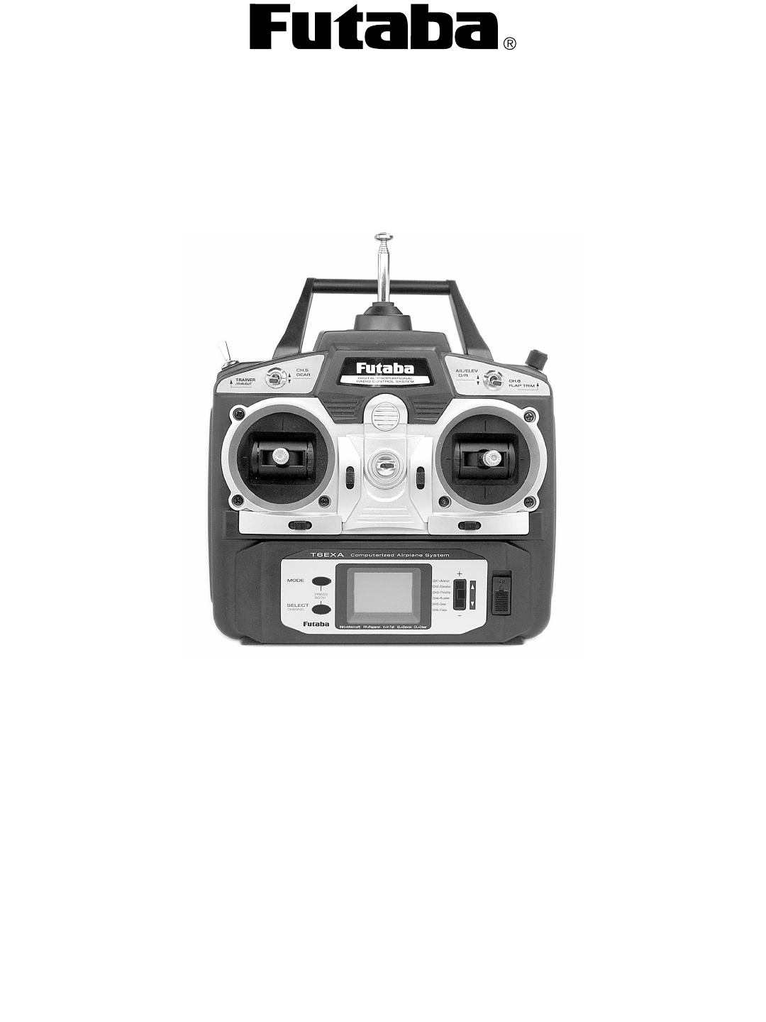
Futaba T6EXA-72 6 Channel Aircraft Radio Control User Manual 6EXA2
Futaba Corporation 6 Channel Aircraft Radio Control 6EXA2
Futaba >
Contents
- 1. Users Manual Part 1
- 2. Users Manual Part 2
- 3. Users Manual Part 3
- 4. Users Manual Part 4
Users Manual Part 1

IINNSSTTRRUUCCTTIIOONN MMAANNUUAALL
ffoorr FFuuttaabbaa 66EEXXAA 6-channel,
FM radio control system for aircraft
Futaba Corporation
Technical updates available at: http://www.futaba-rc.com
FUTZ9032 for FUTK55** V1.0Entire Contents © Copyright 2003
66
EEXXAA

INTRODUCTION
Thank you for purchasing the Futaba®6EXA digital proportional R/C aircraft system. If this is your first “computer” radio, rest
assured that it is designed to make initial setup and field-tuning of your airplane easier and more accurate than would be if
using a “non-computer” radio. Although this is a beginner or sport system with the requirements of those flyers in mind, in order
to make the best use of your Futaba 6EXA and to operate it safely, you mmust ccarefully rread aall oof tthe iinstructions.
Suggestion: If, while reading the instructions, you are unclear of some of the procedures or functions and become “stuck,”
continue to read on anyway. Often, the function or procedure will be explained again later in a different way providing another
perspective from which to understand it. Another suggestion is to connect the battery, switch and servos to the receiver and
actually operate the radio on your workbench as you make programming changes. Then, you’ll be able to see the effects of
your programming inputs.
2
Introduction ...................................................................................2
Service............................................................................................2
Contents aand sspecifications .......................................................3
Glossary .........................................................................................3
Introduction tto tthe 66EXA ssystem ...............................................4
Transmitter ccontrols aand ddescriptions ......................................4
Radio iinstallation .........................................................................5
Receiver aand sservo cconnections ................................................7
Charging tthe NNi-CCd bbatteries ......................................................7
LCD aand PProgramming ccontrols.................................................8
Programming tthe TT6EXA rradio ..................................................9
Model select/Data reset ....................................................10
Servo reversing....................................................................10
Dual rates.............................................................................10
Exponentials.........................................................................11
End Point Adjustments.......................................................11
Trims......................................................................................12
Programmable Mixer..........................................................12
Pre programmed “wing” mixing .......................................13
Flow chart.............................................................................16
Other TT6EXA ffunctions ..............................................................17
Trainer switch.......................................................................17
Flap control lever.................................................................17
Adjustable-length control sticks .......................................18
Changing the stick mode...................................................18
Flying ssafety gguidelines ............................................................18
Flight ppreparation ......................................................................19
Frequency CChart .........................................................................20
Futaba AAccessories....................................................................20
Model DData RRecording SSheets .................................................21
TABLE OOF CCONTENTS
This product is to be used for sport and recreational flying of radio-control models only. Futaba is not
responsible for the results of use of this product by the customer or for any alteration of this product,
including modification or incorporation into other devices by third parties. Modification will void any
warranty and is done at the owner’s risk.
Protect the environment by disposing of rechargeable batteries responsibly. Throwing rechargeable
batteries into the trash or municipal waste system is illegal in some areas. Call 1-800-8-BATTERY for
information about Ni-Cd battery recycling in your area.
SERVICE
If any difficulties are encountered while setting up or operating your system, please consult the instruction manual first. For
further assistance you may also refer to your hobby dealer, or contact the Futaba Service Center at the web site, fax number
or telephone number below:
www.futaba-rrc.com
Fax: ((217) 3398-77721
Telephone ((8:00 aam tto 55:00 ppm CCentral ttime MMonday tthrough FFriday): ((217) 3398-88970, eextension 22
If unable to resolve the problem, pack the system in its original container with a note enclosed and a thorough, accurate
description of the problem(s). Include the following in your note:
•Symptoms. •Any unusual mounting conditions.
•An inventory of items enclosed. •The items that require repair.
•Your name, address, and telephone number. •Include the warranty card if warranty service is requested.
Send your system to the authorized Futaba R/C Service Center at the address below:
Futaba SService CCenter
3002 NN AApollo DDrive SSuite 11
Champaign, IIL 661822

GLOSSARY
It will be helpful to understand the following terms before reading the rest of the manual. The terms are not in alphabetical
order, but are in a logical order that prepares the reader for understanding the next term.
Reversing ((servo rreversing) – A function that allows the user to determine the direction of response of each servo. If, after
hooking up the servos, a control on the model responds in the wrong direction, the user may change the servo’s direction so
the control responds correctly.
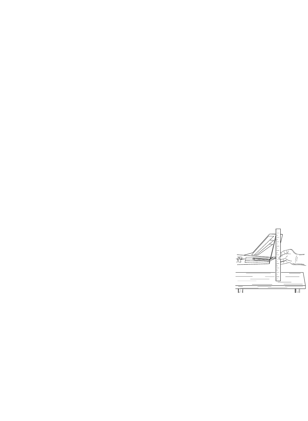
Throw – When speaking of a control surface (such as an elevator or aileron), the throw is the
distance the surface moves. Control surface throw is usually measured at the trailing edge of the
surface and is expressed in inches or millimeters. The model in the diagram has 1/2" [13mm] of
up elevator throw. Throw can also refer to the distance a servo arm (or wheel) travels.
Dual rrate ((D/R) – On the 6EXA the dual rate switch allows you to instantly switch, in flight,
between two different control throws for the aileron and elevator. Often, different control
throws are required for different types of flying. (“Low” throws may be required for flying at
high speeds where the model’s response becomes more sensitive, and “high” throws may be required for aggressive aerobatic
maneuvers or landing or flying at lower speeds where the model’s response becomes less sensitive.)
End ppoint aadjustment ((E.P.A.) – Sets the overall, maximum distance the servo rotates in either direction. (No matter where the
dual rates are set, the servo will never travel beyond the limit set by the end point adjustment.)
Exponential – Normally, servos respond proportionally to control stick input from the transmitter (e.g., if the stick is moved halfway,
the servo will move halfway). However, with “exponential,” the servo can be made to move more or less than initial stick movement
(less servo movement is more common). Exponentials are commonly used to “soften,” or decrease initial servo travel for the ailerons
and elevators. This way, initial control stick inputs from the pilot result in small servo movement for a smoother flying airplane. (Dual
rates adjust the amount of servo travel. Exponentials determine where most of the travel will occur.)
Mixing – Two (or more) servos can be made to operate together either by mechanically joining the wires (with a Y-connector)
or by electronically “joining” them through programming functions in the transmitter. When servos are electronically joined via
programming, they are said to be “mixed.” Unlike joining servos with a Y-connector, when servos are mixed electronically they
can be made to move in opposition. Additionally, each servo’s end points can be independently set.
3
Transmitter:
T6EXA Transmitter with programmable mixing and 6-model
memory.
Transmitting on 72 MHz band.
Operating system: 2-stick, 6-channel system
Modulation: FM
Power supply: NT8S600B 9.6V, 600 mAh Ni-Cd battery
Current drain: 250mA
Receiver:
R127DF narrow band, FM seven-channel receiver.
Receiving on 72 MHz band.
Type: FM, Dual conversion
Intermediate frequencies: 455kHz, 10.7MHz
Power requirement: 4.8V or 6V Ni-Cd battery
Current drain: 14mA @ 4.8V
Size: 1.39x2.52x0.82” (35.3x64.0x20.8mm)
Weight: 1.5oz (42.5g)
Receiver BBattery:
NR-4J 4-cell (4.8 Volt)
Capacity: 600mAh
Weight: 3.4oz/95g
Servos:
Four S3004 ball bearing servos with mounting
hardware and servo arm assortment
Control system: Pulse width control, 1.52ms neutral
Power requirement: 4.8V (from receiver)
Output torque: 44.4oz-in [3.2kg-cm]
Operating speed: 0.23sec/60°
Size: 1.59x0.78x1.41” [40.4x19.8x36mm]
Weight: 1.3oz [37.2g]
*Specifications and ratings are subject to change without
notice.
Other ccomponents:
• SWH-13 switch harness with charging jack
• 9” [150mm] aileron extension cord (to facilitate quick connecting
and disconnecting of aileron servo with removable wing)
• Flap control lever
• AC overnight battery charger
• Frequency clip
• Neck strap
• Servo mounting tray
• Instruction manual
CONTENTS AAND SSPECIFICATIONS