Futaba T6EXA-72 6 Channel Aircraft Radio Control User Manual 6EXA2
Futaba Corporation 6 Channel Aircraft Radio Control 6EXA2
Futaba >
Contents
- 1. Users Manual Part 1
- 2. Users Manual Part 2
- 3. Users Manual Part 3
- 4. Users Manual Part 4
Users Manual Part 2
INTRODUCTION TTO TTHE 66EXA SSYSTEM
IMPORTANT!: Always turn on the transmitter first, then the receiver. When turning off the system, always turn off the receiver
first. The object is never to have the receiver on by itself. Otherwise, the servos or control surfaces could be damaged, or in the
case of electric-powered models, the motor may unexpectedly turn on causing severe injury.
IMPORTANT!: Never collapse the transmitter antenna by pushing down from the top. If one of the segments becomes momentarily
stuck you may damage the antenna. Instead, collapse the antenna from the bottom, drawing in one segment at a time.
Transmitter
The T6EXA FM 6-channel transmitter may be used with any Futaba, narrow band, FM receiver. The liquid-crystal display (LCD)
on the face of the compact, ergonomically-designed case is easy to read and allows rapid data input. The system also holds
independent memories for six different models. The new, adjustable-length control sticks provide an improved feel. External
switches operate dual rates (D/R), landing gear, and trainer cord or “buddy-box” capabilities. Programming features include
servo reversing and E.P.A on all channels, dual rates, exponentials and programmable mixing. Additionally, any one of four,
factory-set, preprogrammed “wing-type” mixers including flaperon, V-tail, elevon or flaperon + V-tail mixing may be selected.
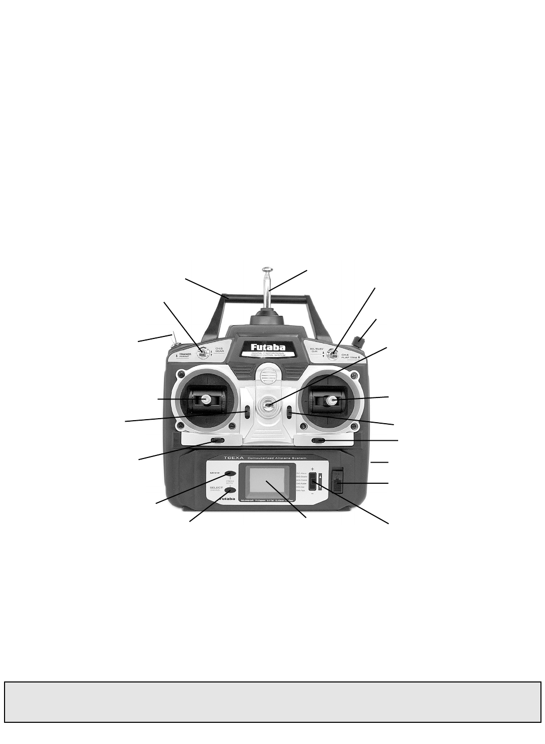
Transmitter ccontrols
The diagram and explanations briefly describe the functions of the Futaba T6EXA transmitter. Full instructions on how to
operate the controls are provided beginning on page 9.
NOTE: The diagram shows a Mode 2 system as supplied. (More on flight modes on page 18).
DESCRIPTIONS:
Aileron aand EElevator ddual rrate sswitch
Use this switch to “flip” between two aileron and elevator control throw settings. The throws can be set up however you prefer,
but generally, when the switch is “up” the throws are greater (“high rate”) and when the switch is “down” the throws are less
(“low rate”). This switch also flips between exponential rates (if used).
Flap ccontrol ddial/Channel 66- This dial operates the servo connected to channel 6 in the receiver—if your model has flaps this
is the control used to operate them.
Neck sstrap hhook - Mounting point for optional neck strap.
Aileron/elevator ccontrol sstick - Operates the servos connected to channel 1 (aileron) and channel 2 (elevator) in the receiver.
Trim llevers ((all) - Used to shift the neutral or center position of each servo as labeled in the diagram.
NOTE: The throttle trim lever is intended for fine tuning the throttle servo when the engine is at idle. Throttle trim does not
affect the throttle servo when the throttle control stick is all the way up (so idle r.p.m. can be adjusted without affecting
throttle settings through the rest of the stick movement).
4
Aileron & Elevator
dual rate switch
Antenna
Retractable landing
gear switch / CH.5
Flap control
dial / CH.6
Carrying handle
Liquid-crystal display
screen (LCD)
Throttle/rudder
control stick
MODE key
SELECT key
Trainer /throttle
cut switch Neck strap hook
Charging jack
On-off switch
Rudder trim
lever
Throttle trim
lever
DATA INPUT lever
Aileron trim lever
Elevator trim lever
Aileron/elevator
control stick
Charging jjack – Port for charging the transmitter batteries with the included battery charger.
On-ooff sswitch
DATA IINPUT llever – Used to change the values of the various functions displayed on the LCD screen.
Liquid-ccrystal ddisplay sscreen (LCD) – Displays programming modes and values entered.
MODE kkey - Used to scroll through and display the seven different functions.
SELECT kkey - Used to display the values for the current function.
Throttle/rudder ccontrol sstick - Operates the servos connected to channel 3 (throttle) and channel 4 (rudder) in the receiver.
Trainer/throttle-ccut sswitch - Operates both the trainer and throttle-cut functions. To operate as a trainer switch the transmitter
must be connected to another transmitter via. a trainer cord (available separately). To use the throttle-cut function, lower the
throttle stick all the way, then rapidly depress the switch twice to fully close the carburetor and shut off the engine.
Retractable llanding ggear sswitch/Channel 55– Switch operates the servo connected to channel 5 in the receiver—if your model
has retractable landing gear this is the control used to extend and retract the gear.
Antenna – Radiates signals to the receiver. Never fly a model without fully extending the antenna or you may create
interference to other modelers and decrease operational signal range of the transmitter. The antenna may be removed and
replaced with another in case it is inadvertently broken.
RADIO IINSTALLATION
Follow these guidelines to properly mount the servos, receiver and battery.
•Make certain the alignment ttab on the battery, switch and servo connectors is oriented correctly and “keys” into the
corresponding notch in the receiver or connectors before plugging them in. When unplugging connectors, never pull on the
wires. Always pull on the plastic connector instead.
•If any servo wires are not long enough to reach the receiver, servo extension wires (available separately) may be used.
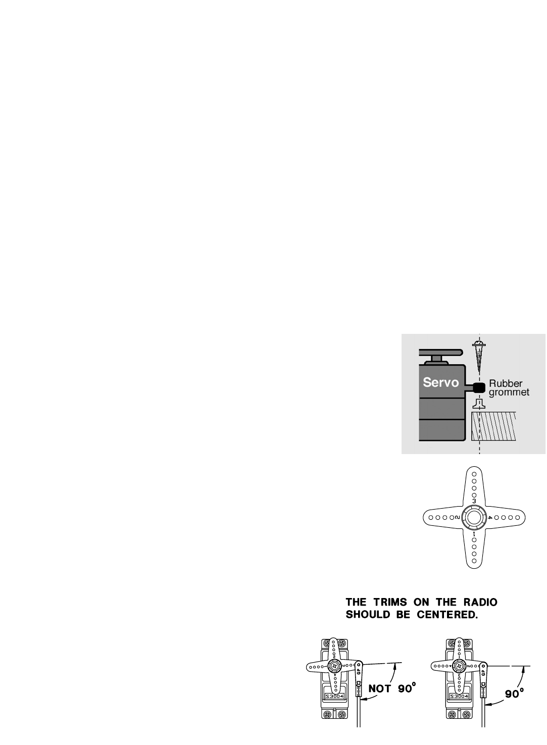
•Always mount the servos with the supplied rubber ggrommets. Do not over tighten the
screws. No part of the servo casing should contact the mounting rails, servo tray or any
other part of the airplane structure. Otherwise, vibration will be transmitted to the servo
causing premature wear and/or servo failure.
•Note the small numbers (1, 2, 3, 4) molded into each arm on the Futaba 4-arm servo
arms. The numbers indicate how many degrees each arm is “off” from 90 degrees to
correct for minute manufacturing deviations from servo to servo.
•To center the servos, connect them to the receiver and turn
on the transmitter and receiver. Center the trims on the
transmitter, then find the arm that will be perpendicular to
the pushrod when placed on the servo.
5
•After the servos are installed, operate each servo over its full travel and check that the pushrods and servo arms do not
bind or contact each other. Also make sure the controls do not require excess force to operate. If there is an objectionable
buzzing sound coming from a servo, there is probably too much resistance in the control. Find and correct the problem.
Even if there is no servo damage, excess battery drain will result.
•Use the mounting pplate from the receiver on/off switch as a template for the cutout and screw holes. Mount the switch on
the side of the fuselage opposite the engine exhaust, and where it won’t be inadvertently turned on or off during handling
or storage. Be certain the switch moves without restriction and “snaps” from ON to OFF, and that the cutout allows full
motion of the switch in both directions.
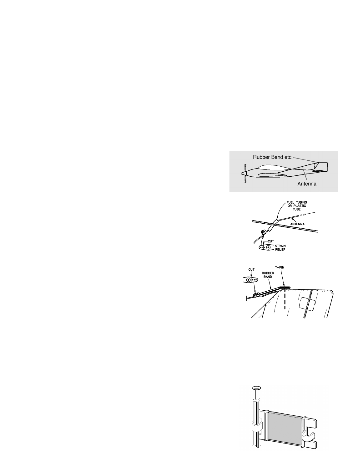
•IMPORTANT: NNEVER cut the receiver antenna or mount it in the model folded back on itself. Doing so will change its
electrical length, possibly reducing the distance from the pilot that the model can be controlled (“range”).
•The receiver antenna may be mounted inside or outside the model:
Internal aantenna mmounting:
The antenna may be routed down through the inside of the fuselage, or through any non-mmetallic housing or tube within the
fuselage. Keep the antenna away from metal pushrods, wires and cables; otherwise, range may be decreased. Always perform
a range check before flying (see page 19).
External aantenna mmounting:
A. Use a cut off servo arm as a ”stop” or strain
relief inside the fuselage to keep
tension off the solder joint holding the antenna to the receiver. Guide the antenna
through a hole in the fuselage. (If possible, insulate the hole with a rubber grommet or
a small piece of rubber tubing.)
B. Make a hook from another cut off servo arm. Insert the end of the antenna
through two holes, then connect the hook to a rubber band around a pin inserted into
the vertical stabilizer. Allow any excess antenna length to trail behind the hook.
•The receiver contains precision electronic parts. It is the most delicate (and expensive) radio component on-board the model
and should be protected from vibration, shock and temperature extremes. To protect the receiver, wrap it in R/C foam rubber
or other vibration-absorbing material. If appropriate, waterproof the receiver by placing it in a plastic bag and closing the open
end with a rubber band before wrapping it in foam. If moisture enters the receiver, intermittent operation or a failure may
result. Wrapping the receiver in a plastic bag also protects it from fuel and exhaust residue which, in some models, can work
its way into the fuselage.
Mounting tthe ffrequency cclip:
•To announce your frequency and avoid potential interference problems, the
frequency number should always be displayed on the transmitter antenna while
flying. Peel the backing from the numbers and apply them to both sides of the
clip. Snap the end of the clip that fits best to the base of the antenna as shown.
You may cut off the other end of the clip.
6
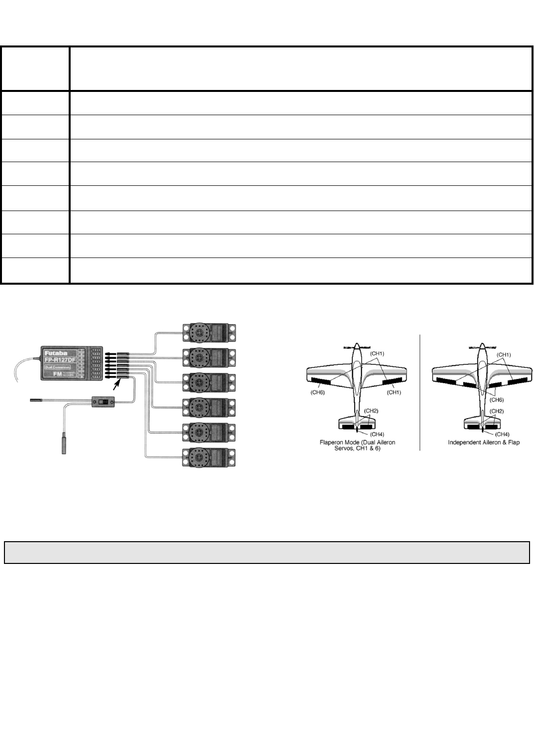
RECEIVER AAND SSERVO CCONNECTIONS
Connect
the
servos
to
the
receiver
to
perform
the
functions
indicated:
The diagram shown is for aircraft models only. Additional servos may have to be purchased separately.
CHARGING TTHE NNi-CCd BBATTERIES
The transmitter and receiver batteries included with your 6EXA system are rechargeable, Ni-Cd (nickel-cadmium, pronounced
‘ni
- •kad) batteries. Ni-Cd batteries require special care and charging. Read tthe ccharging iinstructions ccarefully.
1. Connect the transmitter ccharging ccord coming from the A/C wall charger to the charge jack in the right side of the
transmitter case. The receiver ccharging ccord may be connected to the batteries two different ways: The charge cord may be
connected directly to the battery pack, or to the vacant charge connector (black) coming from the on/off switch in the model.
Charging “through the switch” is preferred as there will be no need to disconnect the battery.
2. Plug the A/C wall charger into a wall outlet. Note: If the wall outlet can be turned off by a switch in the room, be certain the
switch remains on after leaving the room. Otherwise, the batteries will not be charged!
3. The LEDs (light-emitting diodes) should light red, indicating that current is flowing and the batteries are being charged.
Discharged batteries will take about 15 hours to fully charge. If using an aftermarket fast charger, be ccertain tto ffollow tthe
manufacturer’s iinstructions pprovided wwith tthe ccharger so you do not overcharge the batteries. NEVER charge the batteries
NOTE: The batteries are supplied partially charged but will require a full, overnight charge before the model may be flown.
7
Receiver
output Function
channel
1 Aileron -or- right flaperon -or- right elevon (for tailless models)
2 Elevator -or- right ruddervator (for V-tail models) -or- left elevon (for tailless models)
3 Throttle
4 Rudder -or- left ruddervator (for V-tail models)
5 Retractable landing gear
6 Flap -or- left flaperon
7 Not used
B/8 Receiver on/off switch (the plug colored red goes into the receiver)
Flap (or 2nd
Flaperon) Servo
(CH6)
Gear Servo
(CH5)
Rudder Servo
(CH4)
Throttle Servo
(CH3)
Elevator Servo
(CH2)
Aileron Servo
(CH1)
Receiver
Charging
Jack
(Black)
Switch
Harness
To Battery
(Red)
at a rate higher than 1,000mAh. The batteries should also be discharged periodically to prevent a condition called
“memory.” If, for example, only two flights are made each time you go flying, the batteries will not have “reached” very far
down into their full capacity. After doing this several times the batteries will “remember” and eventually “think” they can
supply only enough power for two flights. After two flights the batteries may not provide enough power to operate the system,
thus causing a crash. To erase any potential memory, cycle the batteries by discharging, then charging them with a
commercial battery cycler, or leave the system on and exercise the servos by moving the transmitter sticks until the servos
are moving very slowly, indicating that the battery is discharged. Cycling should be done every one to two months, even
during the winter or periods of long storage. If using a cycler with a readout, note the capacity after the batteries have been
cycled. If there is a noticeable drop in capacity the batteries should be replaced.
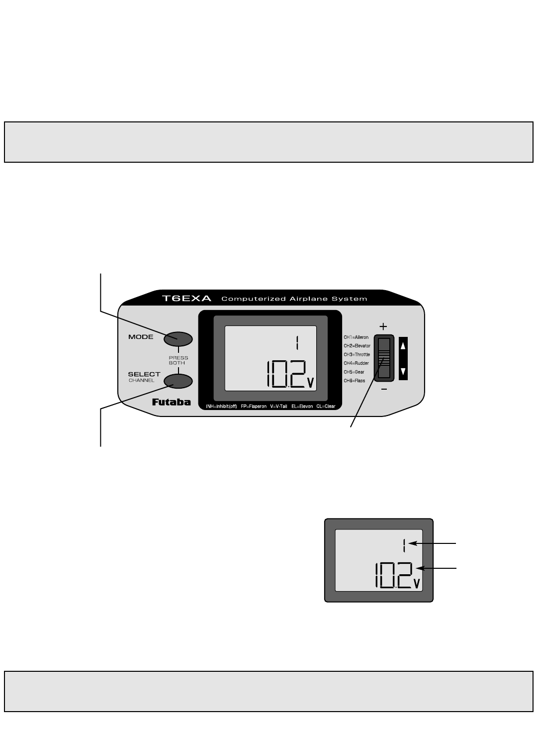
LIQUID CCHIP DDISPLAY ((LCD) && PPROGRAMMING CCONTROLS
LCD ddisplay sscreen
When the transmitter is initially turned on, the model mmemory nnumber
and transmitter bbattery vvoltage are displayed on the LCD screen. When
prompted by the user, the functions and settings stored in the memory
can also be read on the screen. The user accesses the different functions
using the MODE and SELECT keys and changes the values and settings
using the DATA INPUT lever. (This is called programming!)
Note: Feel free to explore by scrolling through the programs and viewing the displays using the MODE and SELECT keys. The
MODE and SELECT keys only determine what will be displayed on the screen and will not change any of the settings. Only
when using the DATA INPUT lever will you be able to change any of the settings.
Note: Charging your batteries with the included Futaba A/C battery charger is always safe. However, fast-charging with an
aftermarket charger is acceptable as long as you know how to properly operate the charger. NEVER charge at a rate higher
than 1,000 mAh (1 Amp). If not done correctly, fast-charging can damage the batteries.
8
MODE key - use to select desired
function while programming
To open
programming menu;
Press both keys
simultaneously and
hold for one second
SELECT key - use to select items within
function to be set or changed in the screen
DATA INPUT lever - use this lever to input
numbers or settings
Current
model memory
Transmitter
battery voltage
Model mmemory nnumber
The Futaba T6EXA stores model memories for six models. This means all the data (control throws, trims, end points, etc.) for up
to six different models can be stored in the transmitter and activated at any time (depending upon which model you choose to fly
that day). This eliminates the requirement for reconfiguring the transmitter each time you decide to fly a different model with it!
When the transmitter is turned on the model nnumber and the transmitter voltage will be indicated on the LCD screen. Before every
flight BE CCERTAIN that the correct model number for the model you intend to fly appears on the screen. If the transmitter is not
operating the correct model, some (or all) of the controls could be reversed and the travels and trims will be wrong.
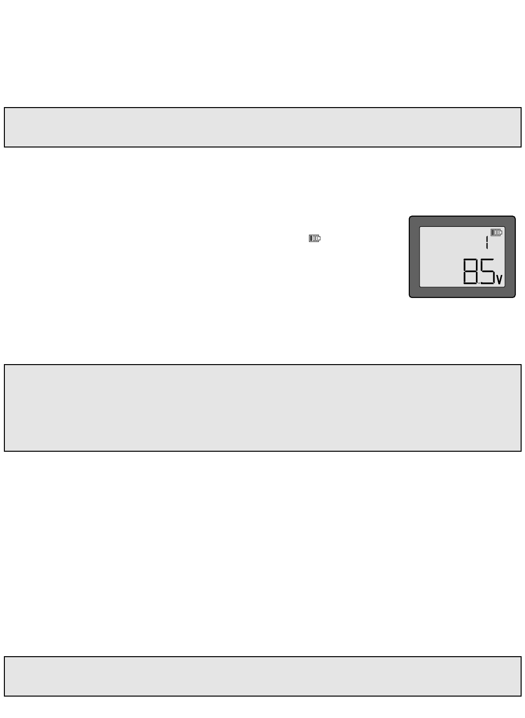
Transmitter bbattery vvoltage
In addition to the model number, the LCD screen also displays the transmitter bbattery vvoltage.
When the voltage goes below approximately 8.5 VVolts the “battery” icon will f
fl
la
as
sh
hand the
low-battery alarm will continuously “beep” until the transmitter is turned off. When the low-
battery alarm sounds you will have approximately four minutes (or less) to land your model
before losing control. You should never allow the transmitter voltage to become this low while
flying, but if it does, land immediately.
PROGRAMMING TTHE 66EXA RRADIO
Anytime you wish to view or change any of the current settings in the transmitter, the programming mode must first be entered
by, of course, turning on the power, then by pressing the “MODE” and “SELECT” keys simultaneously and holding them down
for one second. Once “in the program” the MODE key will be used to scroll through each of the seven functions (model number,
reversing, dual rates & exponentials, end point adjustments, trim, programmable mix and the pre-programmed “wing” mixing)
and the SELECT key will be used to view the settings within the function. When a data change is actually required the “DATA
INPUT” lever will be used to increase or decrease the value of the item displayed, thus making the change.
You can return to the “home” screen (where the model number and battery voltage is displayed) by pressing the MODE and
SELECT keys simultaneously and holding them down for one second.
Note: The functions are listed and described in the order that they appear in the transmitter. Read all the way through the
programming instructions before setting up your model (if you won’t be using any of the mixing functions for a while you
can read those instructions when ready). Refer to the FLOW CHART on page 16 as well.
Note: When the transmitter voltage reads 8.9 VVolts you will
still have approximately ten minutes (or less) before losing
operational range, so this is the recommended absolute
minimum voltage. If the transmitter ever reaches 8.9 Volts,
land as soon as safely possible. A more reasonable margin
of safety would be to quit flying for the day (or recharge the
batteries) when the transmitter battery is at 9.4 Volts.
SUGGESTED GGUIDELINES
9.4 Volts – No more flying until recharge.
8.9 Volts – Land as soon as safely possible.
8.5 Volts – Emergency – Land iimmediately!
Flying a model with the wrong program will result in a crash, so always be ccertain the model number in the transmitter is
correct. One way to ensure this is to write the corresponding model number directly on the airplane, or attach a list to the
bottom or back of the transmitter.
9