Futaba T7PX-24G Radio Control User Manual
Futaba Corporation Radio Control
UserManual.wiki
>
Futaba
>
T7PX-24G User Manual
>
User Manual (P1-40)
Contents
1.
User Manual (P1-40)
2.
User Manual (P41-116)
3.
User Manual (P116-192)
User Manual (P1-40)
Navigation menu
Upload a User Manual
Namespaces
Wiki Guide
HTML
PDF
Info
Views
User Manual
Discussion / Help
Navigation
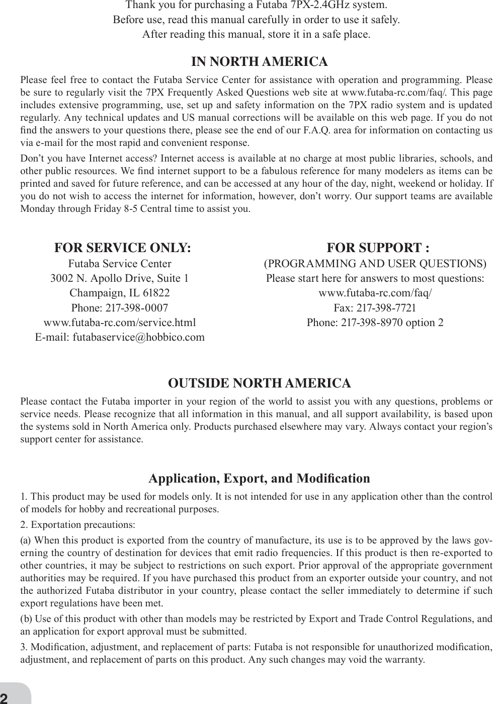


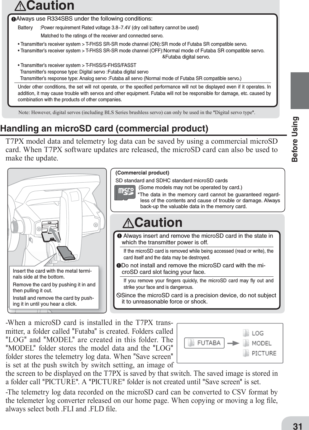

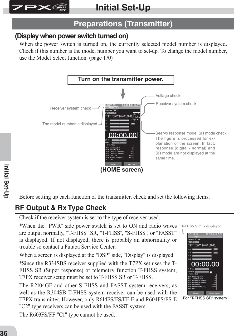
![HOME Menu Linkage menu Receiver* Even with the same receiver,if you change the system, besure to rink with the receiverand power cycle the receiver.(Pages 38 to 39)S-FHSS/FASST T-FHSS T-FHSS SR37Initial Set-UpReceiver system Change & How To LinkFirst set up the receiver. Setting changes are immediately reÀected. Next, the transmitter and receiver are linked and the receiver memorizes the transmitter ID number so that sig-nals from other transmitters will not be received.In addition, with the T-FHSS telemetry system, the transmitter simultaneously memorizes the receiver ID numbers so that data from other receivers will not be received.The method of setting up the receiver system and the method of linking the transmitter and receiver are described. Refer to the ¿gure at the right for the edit buttons used.1 Set the transmitter "PWR" side power switch to ON. From the Home screen, press theHome button or tapped [Menu] on the touch panel. Next, select [Receiver] at the Linkage menu and access the setup screen shown below by tapping the screen.2 In "Receiver", select and tap the system to be set from T-FHSS SR, T-FHSS, S-FHSS,FASST. The confirmation screen will be displayed. To execute, tap [Yes] to hear an electronic sound and finish setting. To cancel, select [No] and touch it. If you change the system, be sure to link it with the receiver and turn the power on again.](https://usermanual.wiki/Futaba/T7PX-24G.User-Manual-P1-40/User-Guide-3526468-Page-36.png)
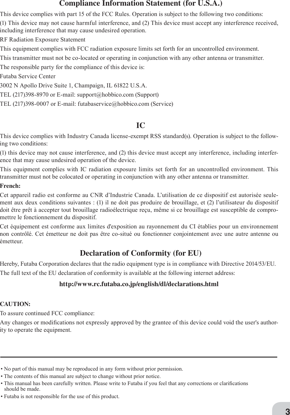
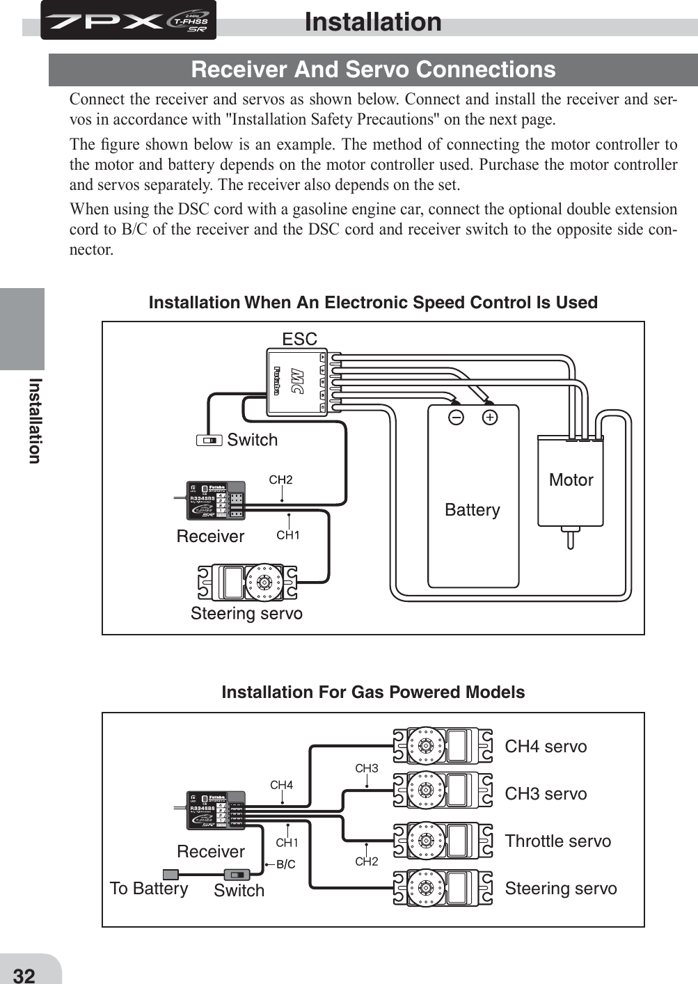
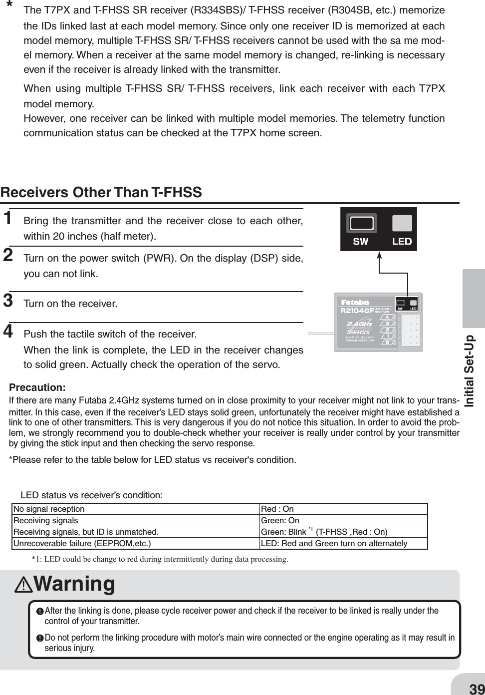
![ReceiverR334SBSLink failedLink establishedT-FHSS T-FHSS SRThe link is completed. Repeat the linking operation38Initial Set-Up* After set up this far is complete, when using a FASST system (R614FS/FF/FF-E) or S-FHSS system (R2104GF, R204GF-E, etc.) receiver, go to "Receiver other than T-FHSS" on page 39. When using a telemetry function T-FHSS SR receiver (R334SBS) and T-FHSS re-ceiver (R304SB, etc.) , go to step. 3 Bring the transmitter and receiver within 50cm of each other (antennas do not touch) and turn on the receiver power.4 Touch [Link] on the transmitter T7PX screen, you will hear a chime sound and T7PX will enter the link mode for 20 seconds. During the 20 second link mode, push the receiver side push switch for about 2 seconds or more.5 During the 20 seconds link mode, press the receiver tactile switch for at least 2 seconds. The LED blinks red and then changes to a greenish red green steady light. When the T7PX makes a beeping sound and the message "Link with receiver" appears on the screen, release the receiver tactile switch. This ends reading of mutual ID and displays the memo-rized receiver ID number on the T7PX screen. Power cycle the receiver. If the "Receiver not found" error screen is displayed, linking failed. Check the set contents and repeat the linking operation.](https://usermanual.wiki/Futaba/T7PX-24G.User-Manual-P1-40/User-Guide-3526468-Page-37.png)
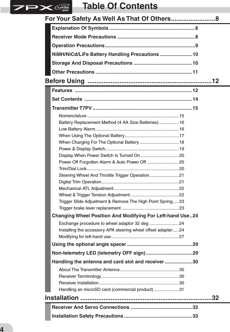
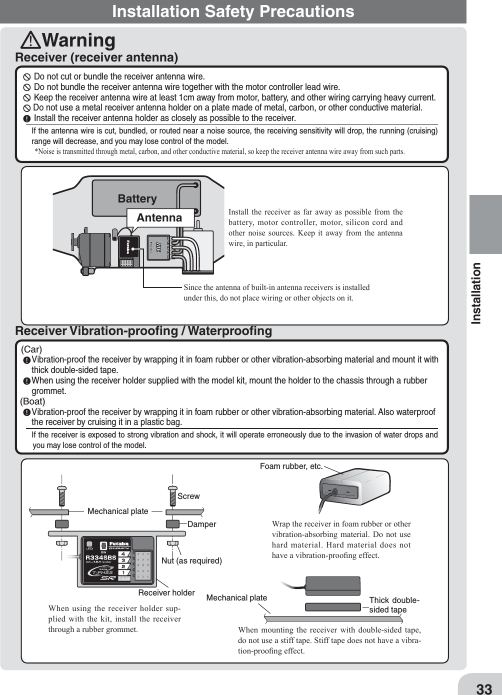
![Response mode is displayed."Digital servo""Analog servo"Display ON / OFF of SR mode.In the case of the channel indicated as [SR], SR mode is ON. If it is not displayed, SR mode is OFF.For SR mode, ON / OFF can be set for each channel.T-FHSS T-FHSS SRHow to set the response / SR modeHOME Menu Linkage menu ReceiverReceiverFrom a digital servo to an analog servoChanges to an analog servoChanges to a digital servoFrom an analog servo to a digital servo40Initial Set-UpIf the setting is incorrect, change it by the following method.Response Mode/ SR Check Make sure that the response mode or SR mode setting matches the servo or other equipment to be used.1 From the Home screen, press the Home button or tapped [Menu] on the touch panel. Next, select [Receiver] at the Linkage menu and access the setup screen shown below by tapping the screen.2 For the T-FHSS / S-FHSS / FASST system, touch [Digital Servo] or [Analog Servo] in the receiver setting and make changes. The display changes when mode is changed.When the power of the receiver is turned on, be sure to turn the power off and then on again.](https://usermanual.wiki/Futaba/T7PX-24G.User-Manual-P1-40/User-Guide-3526468-Page-39.png)
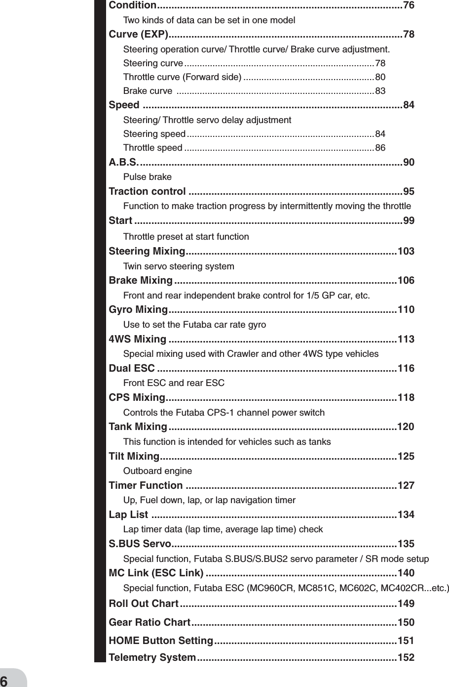
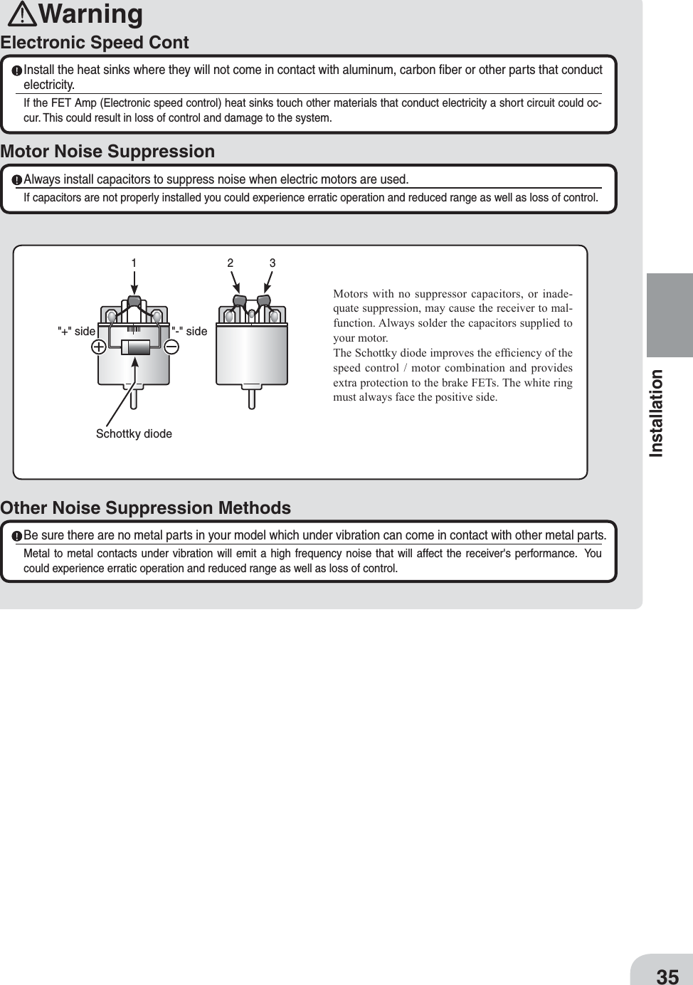
![To change SR mode setting, tapped [Yes], and if you want to cancel, tapped [No].The servo operation confi rmation message is displayed. With this screen displayed, turn the power of the receiver off and on again and check the operation of the servo by actually operating it. If the servo does not operate properly, check the SR mode setting (page 135) of the servo. Tap [Close] to close the screen.By tapping [Servo], you can go directly to the S.BUS servo menu (page 135). Be sure to use the T7PX receiver setting and the servo to be used under predetermined conditions.Under other conditions, the set will not operate, or the specifi ed performance will not be displayed even if it operates. In addition, it may cause servo trouble. Futaba will not be responsible for damage, etc. caused by combination with the products of other companies. T-FHSS SRT-FHSS S-FHSSFASSTSR mode channel: ONSR mode channel: OFF-SR mode of Futaba SR compatible servo.- Normal mode of Futaba SR compatible servo.- Futaba digital servo.- Normal mode of Futaba SR compatible servo.- Futaba digital servo.- Futaba all servo. (Normal mode of Futaba SR compatible servo.) - Normal mode of Futaba SR compatible servo.- Futaba digital servo.- Futaba all servo. (Normal mode of Futaba SR compatible servo.) - Normal mode of Futaba SR compatible servo.- Futaba digital servo.- Futaba all servo. (Normal mode of Futaba SR compatible servo.)Digital servoAnalog servoDigital servoAnalog servoDigital servoAnalog servoSystemResponse / SR node Usable servos41Initial Set-Up In the case of T-FHSS SR, "SR mode" which has greatly improved response compared to the conventional T-FHSS can be used. Tap and change (ON)/ (OFF) of each channel of SR mode. The display changes when you change it. Be sure to turn off the power of the receiv-er before operation check.In SR mode, ON/ OFF can be set for each channel. When using normal servo or ESC, set the SR mode of the connected channel to (OFF). Note: In SR mode ON, normal servo and ESC will not operate. Please set our S.BUS servo corre-sponding to SR mode to SR mode on S.BUS servo menu on page 135 and use it. Also, in case of SR mode OFF, the servo set to SR mode can not be used, so set the servo to normal mode by S. BUS ser-vo menu. If using wrong combination, servo and other equipment will fail, so please be careful.Servo conforming to the setting of response / SR mode](https://usermanual.wiki/Futaba/T7PX-24G.User-Manual-P1-40/User-Guide-3526468-Page-40.png)