Futaba T7PX-24G Radio Control User Manual
Futaba Corporation Radio Control
UserManual.wiki
>
Futaba
>
T7PX-24G User Manual
>
User Manual (P41-116)
Contents
1.
User Manual (P1-40)
2.
User Manual (P41-116)
3.
User Manual (P116-192)
User Manual (P41-116)
Navigation menu
Upload a User Manual
Namespaces
Wiki Guide
HTML
PDF
Info
Views
User Manual
Discussion / Help
Navigation

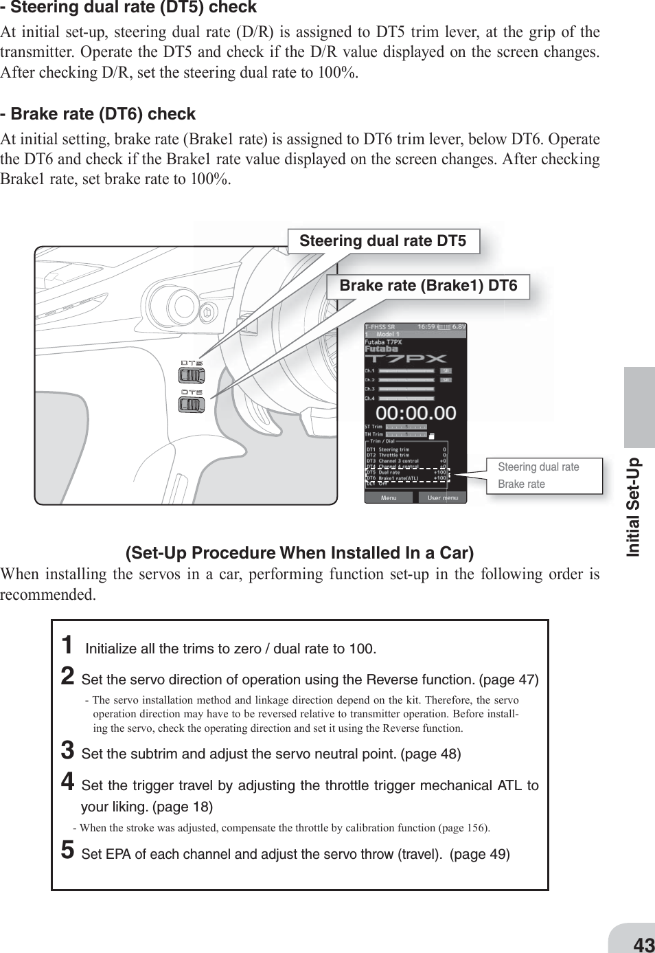
![Push the Home button or tap the touch panel.Press and hold the Home button.Tap [User Menu] on the home screen to display the "User menu" screen.Tap [Menu] on the home screen or press the HOME button to display the menu screen.44Function MapUse the home button and the LCD screen touch panel to operate the screen.In this operation manual, the HOME button is indicated by the following symbols.Function MapMenu Selection(Menu screen)(User menu screen)(Home screen)(End point screen) (Linkage menu screen) (Menu screen)* You can select the screen to display when you press the Home button on the Home screen, menu or user menu. ("Home button setting" of "Accessory menu")* An example is to return from the "End point" screen to the "Home" screen.It returns to the "Home screen" from the function screen in the following method.](https://usermanual.wiki/Futaba/T7PX-24G.User-Manual-P41-116/User-Guide-3526469-Page-3.png)
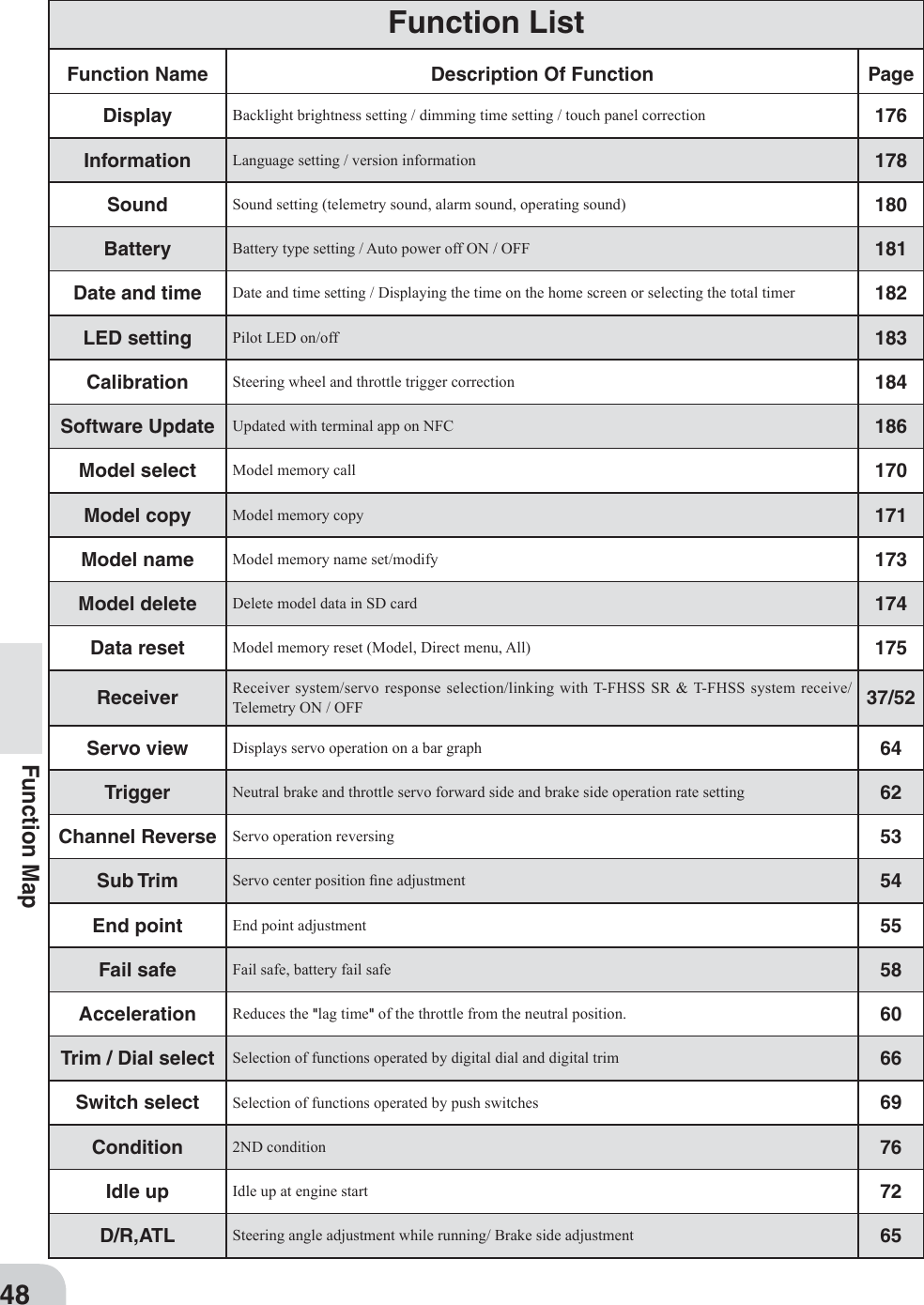
![A screen to display by pushing the home button from the home screen.A screen to display by pressing and holding the home button from the home screen.In addition to the trim lock func-tion, you can select display of specifi c function screen. Tap from the function list and select it.Since there are multiple pages, tap the mark and move the page. When you are done, tap [Close] to fi nish.45Function MapHome Button SettingWhen you push the Home button from the home screen, it moves to the menu screen at the factory shipping the home button. Pushing the Home button on the menu screen or each set-ting screen will return you to the previous screen. Also, if you press and hold the Home but-ton on the Home screen, the trim lock will work and the T7PX can prohibit operations with the digital Trim DT 1 to DT 6 and Dial DL 1 on the main unit. Press and hold the Home button on the menu screen or each setting screen to return to the Home screen. The setting screen moved from the custom menu also moves in the same way and returns to the home screen.You can select the screen to display when you push the Home button on the Home screen, menu or user menu. You can not change the screen to display by push and holding the Home button from the menu screen or each function screen. - Push------------------Display menu screen or custom menu screen. - Long press-----------Trim lock or display the function screen of your choice. "Home button setting" of "Accessory menu" (page 151)(Menu screen) (Accessory menu screen) (Home button setting screen)(Home button setting screen)](https://usermanual.wiki/Futaba/T7PX-24G.User-Manual-P41-116/User-Guide-3526469-Page-4.png)
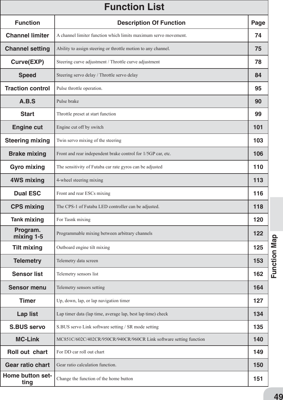
![When resetting is executed, a confi rmation screen is dis-played. To reset, tap [Yes], otherwise tap [No].Example: To change the right-hand side steering amount on the end point screen, tap the right of the steering wheel, and when [-] [reset] [+] is displayed at the bottom of the screen, press + To decrease, tap [-] to change the numerical value. If you leave it tapped, the value changes continuously. Tap [Reset] to return to the initial value.Example: When turning off the auto power off function on the battery setting screen, tap (ON) of auto power off to display (OFF) and the function will be invalid.Example: Tap the display language [Eng-lish] on the system information setting screen, the list screen of available lan-guages will be displayed. To change to Ger-man, touch [German], the screen display becomes German. If you do not want to change, tap [Cancel] to close the screen.* Depending on the function, items may be switched in order by tapping.46Function MapValue Of Each Function And Changing The Set ValueOn the setting screen of each function, if you tap the item to be set, [-] [reset] [+] will be displayed at the bottom of the screen, tap the [-] [+] on the panel Set. Tap[Reset] to return to the initial value. There are items with no [reset].The setting of ON / OFF changes when you tap (ON) or (OFF).To select from multiple items, tap [Item] and tap from the screen of the displayed list to se-lect it.](https://usermanual.wiki/Futaba/T7PX-24G.User-Manual-P41-116/User-Guide-3526469-Page-5.png)
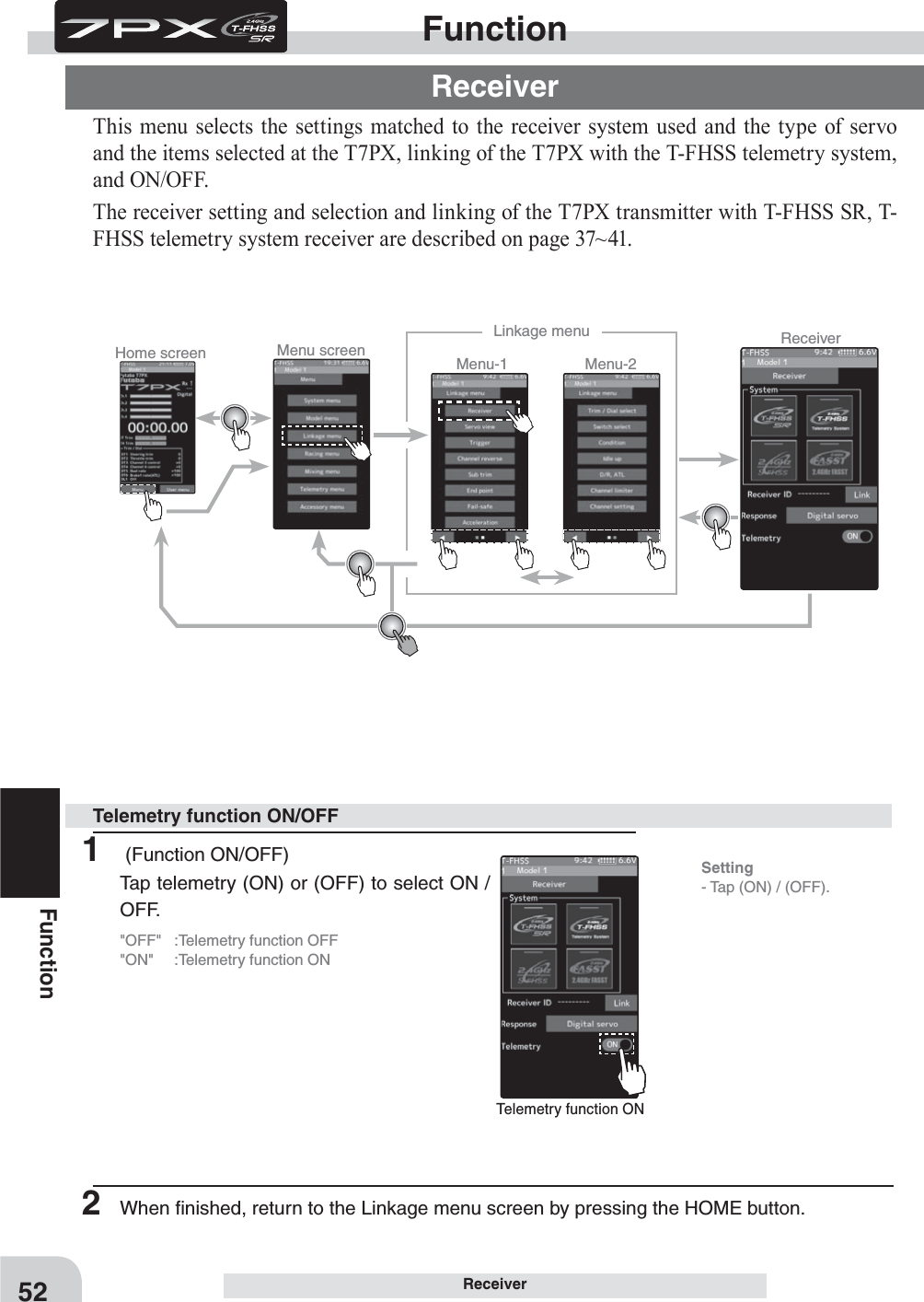
![Tap [Yes] to edit, and tap [No] to cancel.(User menu screen) (User menu setting screen) Tap the place to register. Tap the function to register. Tap [Edit User Menu] and exit.(User menu setting screen) (Function list screen)47Function MapUser MenuThe T7PX allows you to register your favorite functions in the user menu. You can create a different user menu for each model memory, and the user menu will also be copied by model copy (page 171). (8 types on a page, up to 48 types on 6 pages)Displaying And Editing The User Menu ScreenOn the user menu screen, you can display the user menu screen by tapping [User Menu] on the home screen. (See page 44)* It is possible to display by pushing the home button with the "Home button setting" func-tion.1 Touch [Edit] on the user menu screen. A confi rmation screen will appear with "User menu setting Are you sure?" To edit, tap [Yes] to display the edit screen. If you do not want to edit it, please tap [No].Menu assignment2 Tap the place to register the function. A list of the functions that can be selected will be dis-played, so if you tap the function you want to register, it will be registered.3 Tap [Edit User Menu] to exit and return to the user menu screen.](https://usermanual.wiki/Futaba/T7PX-24G.User-Manual-P41-116/User-Guide-3526469-Page-6.png)


![Home screen Menu screen Menu-2Menu-1Linkage menu Channel ReverseFor S-FHSS (analog) system, 5 to 7 channels are displayed on the 2nd page. Tap to change page.54FunctionSub trim 90degUse this function to adjust the neutral position of the steering, throttle, channel 3 and channel 4 servos. (Preparation)- Follow the instructions of the model, install the servo horn and make the next adjustment.- Set the steering and throttle digital trims to the neutral "0" posi-tion. Set auxiliary channels to the center "0" position. - Tap the trim display part of the channel you want to adjust. Value input buttons appears on the Sub-trim menu screen.1 (Sub trim adjustment)Use the [+] or [-] button to adjust the center. (Each channel can be set similarly.)Sub trim adjustmentUse to adjust the neutral position *Sub trim adjusts the entire range of the servo in the set direction.Sub trimAdjustment buttons- Adjust with the [+] and [-] but-tons.- Return to the initial value by tapping the [reset] buttons.Sub trim -100~+100 Initial value : 02 When fi nished, return to the Linkage menu screen by pressing the HOME button.](https://usermanual.wiki/Futaba/T7PX-24G.User-Manual-P41-116/User-Guide-3526469-Page-13.png)

![Home screen Menu screen Menu-2Menu-1Linkage menu Channel ReverseLRDT1For S-FHSS (analog) system, 5 to 7 channels are displayed on the 2nd page. Tap to change page.56FunctionEnd Point(Preparation)- Before setup of the steering end point adjustment, set the steer-ing D/R dial (initial setup: DT5) to the maximum steering angle position 100%.- Tap the travel button of the [Steering Left]. Value input buttons appear on the screen and make the following adjustments:1 Steering (left side) adjustmentTurn the steering wheel fully to the left and use the [+] or [-] buttons to adjust the steering angle.Steering end point adjustmentQuick EPAWhen EPA trim is turned on, the steering angle (end point) can be adjusted by steering trim set digital trim or dial. (Steering trim initial setting: DT1) With the steering wheel turned fully to the right, steering is adjusted by steering trim. Temporarily displayed at this part of the HOME screen as shown in the fi gure below.Steering right side adjustment With the steering wheel turned fully to the left, steer-ing is adjusted by steering trim. Temporarily displayed at this part of the HOME screen as shown in the fi g-ure below.Steering left side adjustment2 Steering (right side) adjustmentTurn the steering wheel fully to the right and use the [+] or [-] buttons to adjust the steering angle.Note Step #1 & #2 are done when the receiver is in the on position installed on the chassis. You’re watching the wheels reach their maximum end point.3 When fi nished, return to the Linkage menu screen by press-ing the HOME button.Adjustment buttons Adjust with the [+] and [-] but-tons.- Return to the initial value by tapping the [reset] buttons.Steering End point :0~140 Initial value :100](https://usermanual.wiki/Futaba/T7PX-24G.User-Manual-P41-116/User-Guide-3526469-Page-15.png)
![57FunctionEnd PointWhen Trigger Ratio (page 62) was set to 100:0, brake operation is stopped and the throt-tle (brake side) cannot be adjusted.Dual ESC mixing :Front ESC4WS mixing: Rear servoSpare channel displayWhen a mixing function is set at a spare channel, the dis-play changes.This is an example of setting dual ESC mixing at the 3rd channel and 4WS mixing at the 4th channel.(Preparation)- Before setting the throttle end point adjustment, set the throttle ATL dial (initial setup: DT6) to the maximum throttle angle po-sition 100%.- Tap the travel button of the [Throttle Forward]. Value input buttons appear on the screen and make the following adjust-ments:1 Throttle (forward side) adjustmentPull the throttle trigger fully to the high side and use the [+] or [-] buttons to adjust the throttle an-gle. However, when using an ESC, set to 100%.2 Throttle (brake side/reverse side) adjustmentMove the throttle trigger fully to the brake side and use the [+] or [-] buttons to adjust the throttle angle. However, when using an ESC, set to 100%.3 When finished, return to the Linkage menu screen by press-ing the HOME button.Throttle end point adjustment(Preparation)- Tap the travel button of the channel you want to set. Value in-put buttons appear on the screen.1 Use the [+] or [-] buttons to adjust the servo angle.Auxiliary channel servo end point adjustmentAdjustment buttons- Use the [+] and [-] buttons to make adjustments.- Return to the initial value by tapping the [reset] buttons.- Please see previous note on page 56.Auxiliary channel End point :0~140 Initial value :100Adjustment buttons- Use the [+] and [-] buttons to make adjustments.- Return to the initial value by tapping the [reset] buttons.- Please see previous note on page 56.Throttle End point :0~140 Initial value :1002 When finished, return to the menu screen by pressing the (END) button.](https://usermanual.wiki/Futaba/T7PX-24G.User-Manual-P41-116/User-Guide-3526469-Page-16.png)
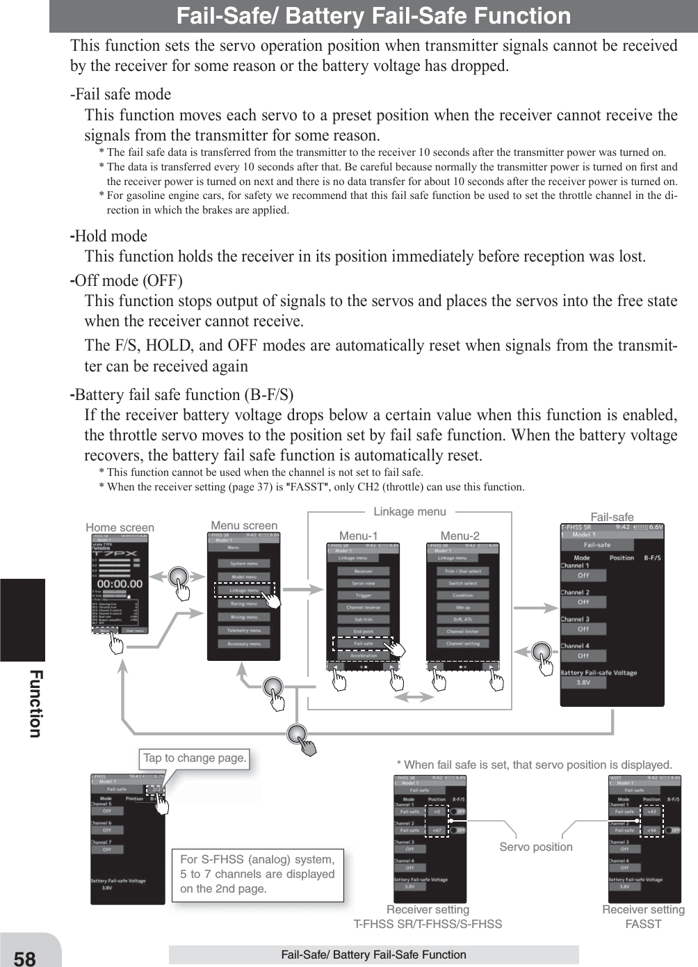
![Fail-Safe position setting While holding the wheel or trig-ger, tap the Fail-Safe position button.Battery fail safe function OFF, ON Initial value: OFFFail safe mode Off, Hold, Fail-safe59FunctionFail-Safe/ Battery Fail-Safe Function1 (Battery fail safe function ON/OFF)Tap B-F /S (ON) or (OFF) of each channel to select ON / OFF.2 (Battery fail safe voltage setting)Tap the voltage display of battery fail safe voltage. Value input buttons appears on the Fail-Sahe menu screen.Use the [+] or [-] button to select the voltage.* Voltage setting is not possible with the S - FHSS sys-tem fixed at 3.8 V. * Since FASST R604 Series receivers are not for high voltage use, the use of LiFe and Li-Po batteries is pro-hibited. Therefore, the 4.75v and 5.5v settings are prohibited. The 5.5 V setting of the FASST system can only be used by the receiver with R614FS (FSE).B-F/S function ON/OFF & Battery Fail-safe voltage settingBattery Fail-safe VoltageT-FHSS SR/T-FHSS 3.8,4.0,4.2,4.4,4.6,4.8,5.0, 5.3,5.6,5.9,6.2,6.5,6.8,7.1,7.4VFASST 3.5,3.8,4.4,4.75 5.5V(Only R614)S-FHSS Only 3.8VExample: Ni-MH /Ni-Cd 4cell---3.8V Ni-MH /Ni-Cd 6cell---4.4V LiFe 2cell---4.75/4.8V Li-Po 2cell---5.5/5.6VWhen the receiver power supply of an electric car uses a common power supply from an ESC, we recommend that this function be set to OFF because the voltage supplied to the receiver may drop momentarily and the battery fail safe function may be activated.(Preparation)- Tap the fail safe part of the channel you want to set. The mode list appears on the Fail-safe menu screen.1 (Mode selection)Tap from the list and select the mode. To cancel, tap [Cancel].(Each channel can be individually set.)Fail safe mode selection1 (Servo position setup)Tap the F/S button of the channel you want to set, and set that channel to the [F/S] mode.Hold the corresponding steering wheel, throttle trigger, or oth-er control in the position you want the servo to move to when the fail safe function is activated, and tap the F/S position but-ton.That position is displayed in percentage.2 When finished, return to the Linkage menu screen by pressing the HOME button. Fail safe function setup2 When finished with hold or off mode setting, return to the Linkage menu screen by pressing the HOME button. When setting fail safe, set the servo position by the following method.3 When finished, return to the Linkage menu screen by pressing the HOME button.](https://usermanual.wiki/Futaba/T7PX-24G.User-Manual-P41-116/User-Guide-3526469-Page-18.png)

![Brake 2 Brake 3 Brake 2&361FunctionAcceleration(Preparation)- Tap the value button of the [Forward]. Value input buttons appear on the screen and make the following adjustments:1 (Forward acceleration amount adjustment)Use the [+] and [-] buttons to adjust the ac-celeration amount. "0" :No acceleration "100" :Maximum acceleration (Approximately 1/2 of the forward side throttle angle)Throttle acceleration adjustmentThe throttle acceleration adjustment amount (Forward), (Brake1), auxiliary channels (Brake2, Brake3) can be controlled with digital trim DT1-DT6 or digital dial DL1 etc. with the dial select function. (page 66) Dial / Trim Setting Adjustment buttons Adjust with the [+] and [-] but-tons.- Return to the initial value by tapping the [reset] buttons.Forward acceleration amount (Forward) 0~100 Initial value: 0Brake side acceleration amount (Brake1) 0~100 Initial value: 0When Trigger Ratio (page 62) was set to 100:0, brake operation is stopped and the throt-tle (brake side) cannot be adjusted.Caution2 (Brake side acceleration amount adjustment)Tap the travel button of the [Brake1]. Value input buttons appear on the screen and use the [+] and [-] buttons to adjust the accelera-tion amount. "0" :No acceleration "100" :Maximum acceleration (Brake side maximum throttle angle)If the "Brake Mixing Function" (page 106) is being set, the auxiliary channel brake side acceleration will become adjustable. 3 When finished, return to the Linkage menu screen by pressing the HOME button.](https://usermanual.wiki/Futaba/T7PX-24G.User-Manual-P41-116/User-Guide-3526469-Page-20.png)
![Home screen Menu screen Menu-2Menu-1Linkage menu TriggerForward 50: Brake 50 Forward 70: Brake 30 Forward 100: Brake 0Ratio mode Forward 50:Brake 50 Forward 70:Brake 30 Forward 100:Brake 062FunctionTriggerThis menu has the following 2 functions:-Servo neutral mode:This function allows selection of the forward side and brake (reverse) side operation ratio from 70:30, 50:50 or 100:0 by changing the neutral position of the throttle servo.-Neutral brake:This is a function select switch function. The neutral brake function ON/OFF switch must be set (see page 69).The neutral brake, which applies the brakes at the neutral position of the throttle trigger, can be set. However, when using the MC950CR, MC851C, MC602C, MC402CR, or other Futaba ESC, con¿rm that the ESC is in the neutral position and the set is in the operation mode before setting the neutral brake function switch to ON.Throttle servo neutral position "Ratio"Trigger1 (Throttle mode selection)- Tap the [Ratio] part.The mode list appears on the Trigger menu screen.Tap from the list and select the mode. To cancel, tap [Cancel].Selecting the trigger ratio2 When finished, return to the Linkage menu screen by pressing the HOME button.](https://usermanual.wiki/Futaba/T7PX-24G.User-Manual-P41-116/User-Guide-3526469-Page-21.png)
![63FunctionNeutral brake "Rate"Trigger(Preparation)- Use the switch select function to the "Switch select". (page 69) When the switch is not set "A switch is not assigned" is dis-played. Tap [Switch select] to display the switch selection screen and set the switch.1 (Neutral brake rate)Tap the value button of the [Rate]. Value input buttons appear on the screen and use the [+] and [-] buttons to adjust the neutral brake rate amount.Neutral Brake function adjustmentAdjust button Adjust with the [+] and [-] but-tons.- Return to the initial value by tapping the [reset] buttons.Neutral Brake 0~100 Initial value: 02 When fi nished, return to the Linkage menu screen by pressing the HOME button.Warning displayIf the power switch is turned on while the neu-tral brake switch is on, an audible alarm will be heard. Immediately set the neutral brake switch to OFF. Neutral brake ON/OFF is indi-cated on the home screen for a few seconds. It is displayed in the home screen, when the neutral brake is ON. When the neutral brake is ON, the display of the throttle trim on the home screen becomes the neutral brake.The ESC neutral brake function and T7PX neutral brake function can be used simulta-neously. However, when setting is dif¿ cult to understand, we recommend that only one neutral brake function be used.ReferenceWhen the neutral brake function is "ON", the neutral brake rate adjustment is automati-cally assigned to the throttle trim (DT1~DT6 or DL1). Dial / Trim Setting Throttle side EPA function, or ATL function setting also affects neutral brake side op-eration. The Idle-up (page 72) or Engine Cut (page 101) function has priority.Effect of set value of other functions on neutral brake](https://usermanual.wiki/Futaba/T7PX-24G.User-Manual-P41-116/User-Guide-3526469-Page-22.png)
![Home screen Menu screen Menu-2Menu-1Linkage menu D/R, ATL65FunctionD/R, ATLD/R (Steering dual rate)The steering left and right servo travels are adjusted simultaneously. This setting is linked to transmitter grip trim DT5. When DT5 is assigned another function, dual rate can be ad-justed with this screen.ATL (Brake1 rate)This function decreases the set value when the braking effect is strong and increases the set value when the braking effect is weak. This function is linked to transmitter grip trim DT6. When DT6 is assigned another function, this function can be set with this screen.D/R, ATL1 Tap the travel button of the [Dual rate]. Val-ue input buttons appear on the screen and use the [+] and [-] buttons to adjust the dual rate amount.This dual rate servo travel is linked to the grip trim.When finished, return to the Linkage menu screen by pressing the HOME button.1 Tap the travel button of the [Brake rate(ATL)]. Value input buttons appear on the screen and use the [+] and [-] buttons to adjust the brake rate amount.This brake rate servo travel is linked to the grip trim.When finished, return to the Linkage menu screen by pressing the HOME button.Dual rate adjustmentBrake rate(ATL) adjustmentAdjust button Adjust with the [+] and [-] but-tons.- Return to the initial value by tapping the [reset] buttons.Dual rate 0~100 Initial value: 0Adjust button Adjust with the [+] and [-] but-tons.- Return to the initial value by tapping the [reset] buttons.Brake rate(ATL) 0~100 Initial value: 0](https://usermanual.wiki/Futaba/T7PX-24G.User-Manual-P41-116/User-Guide-3526469-Page-24.png)
![Home screen Menu screen Menu-2Menu-1Linkage menu Trim / Dial selectSince there are multiple pages, tap the mark and move the page. When you are done, tap [Close] to fi nish.Function list See page 6866FunctionTrim /Dial selectThis function allows selection of the function performed by the digital dial DL1 and digital trimmers (DT1 ~ DT6), step amount adjustment, and operating direction reversal.- The table in page 68 lists the functions that can be assigned to each dial and digital trim. The assigned function is also displayed on the opening screen together with the current adjustment value. They are displayed in DL1 and DT1 ~ DT6 order, from top to bottom.- The step amount can be adjusted. The table in the following page shows the relationship between set value and step amount.- The operation direction can be reversed. (Nor/Rev)Trim /Dial select1 Tap the trim or dial you want to set. (DT 1, 2, 3, 4, 5, 6 / DL 1)The function list appears on the Trim/Dial select menu screen.2(Function setup)Tap and select the function you want to use. To cancel, tap [Close].Function select dial setup](https://usermanual.wiki/Futaba/T7PX-24G.User-Manual-P41-116/User-Guide-3526469-Page-25.png)
![Setting direction- Tap [Nor.] / [Rev.].(Nor.) Normal / (Rev.) ReverseDT5DT6 DT1 DL1DT2DT4 DT367FunctionTrim /Dial select(Changing the operation direction)Tap [Nor.] or [Rev.] in the direction to set the direction.(Changing the operation step amount)Tap the travel button of the [step]. Value in-put buttons appear on the screen and use the [+] and [-] buttons to adjust the step amount.3 When finished, return to the Linkage menu screen by pressing the HOME button.Adjust button Adjust with the [+] and [-] but-tons.- Return to the initial value by tapping the [reset] buttons.Step range 1, 2, 5, 10, 20, 30, 40, 50, 100, 200 Initial value: 2(Setting range: 1, 2, 5, 10, 20, 30, 40, 50, 100, 200)-Steering trim/throttle trimWhen set to the minimum "1", the total trim operating width is 200 clicks. For "100", the total operating width is 2 clicks and for 2PS, the total operating width is 1 click.-Rate, etc. settingThis is the % value which is operated by 1 click relative to the set value of each rate. Since the total operating width of functions having a rate of -100~0~+100 is 200%, when set to "100", the total operating width is 2 clicks. Since the total operating width of functions with a 0~100 rate is 100%, "100" and "200" are operated by 1 click.-Auxiliary channelWhen set to the minimum "1", the total operating width of channel 3 is 200 clicks. For "100", the total operating with is 2 clicks and "200" is operated by 1 click.Relationship between set value and step amount](https://usermanual.wiki/Futaba/T7PX-24G.User-Manual-P41-116/User-Guide-3526469-Page-26.png)
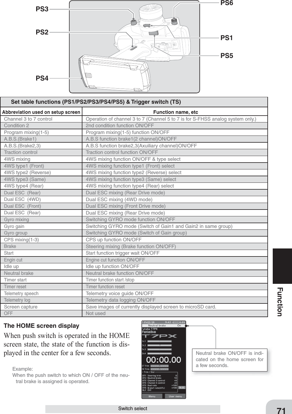
![Home screen Menu screen Menu-2Menu-1Linkage menu Switch selectSince there are multiple pages, tap the mark and move the page. When you are done, tap [Close] to fi nish.The steering switch and trig-ger switch are displayed on the 2nd page.Function list See page 7169FunctionSwitch selectSwitch selectThis function allows selection of the function to be performed by the switches (PS1, PS2, PS3, PS4, PS5, PS6, steering wheel, throttle trigger) and setting of the direction, etc. of op-eration.- The table in the page 71 lists the functions that can be assigned to each push switch. - The push switch PS6 is integrated with the DL 1.- All switches can be made alternating operations (ON/OFF switched each time SW pressed). (Nor/Alt)- The ON/OFF direction can be reversed. The reverse select function always starts from the ON state. However, the steering/ trigger switch is different, depending on the posi-tion. (Nor/Rev)1 (Function setup)Tap the switch you want to set. (PS1, PS2, PS3, PS4, PS5, PS6/ steering wheel, throttle trigger)The function list appears on the switch select menu screen. Tap and select the function you want to use. To cancel, tap [Close].Function select dial setup](https://usermanual.wiki/Futaba/T7PX-24G.User-Manual-P41-116/User-Guide-3526469-Page-28.png)
![Setting direction- Tap [Nor.] / [Rev.].(Nor.) Normal / (Rev.) ReverseSetting type- Tap [Nor.] / [Alt.].(Nor.) Normal / (Alt.) Alternate70Function2(Changing the operation direction)Tap [Nor.] or [Rev.] in the direction to set the direction.(Changing the the type of operation)Tap [Nor.] or [Alt.] in the type to set the type.3 (Steering / trigger switch setting)It is a function that uses the steering wheel and the throttle trigger as a switch.Tap the set value of the position of the steering switch or trigger switch. Value input buttons appear on the screen and use the [+] and [-] buttons to set the switch ON/OFF position. Alternatively, you can set it by hold-ing the steering wheel or throttle trigger at the point where you turn it ON/OFF and tap the [set]. Fine adjustment is possible with [+] and [-].The red range of the bar graph is ON.4 When finished, return to the Linkage menu screen by pressing the HOME button.Adjust button Adjust with the [+] and [-] but-tons.- Return to the initial value by tapping the [reset] buttons.Brake rate(ATL) 0~100 Initial value:100Switch select](https://usermanual.wiki/Futaba/T7PX-24G.User-Manual-P41-116/User-Guide-3526469-Page-29.png)
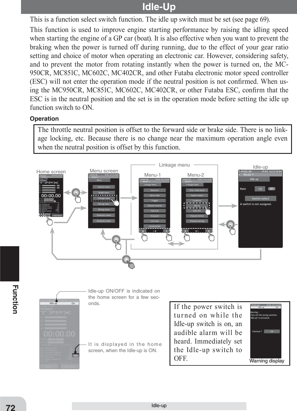
![*Shows the ON/OFF stateAdjust button Adjust with the [+] and [-] but-tons.- Return to the initial value by tapping the [reset] buttons.Idle-up rate -50~0~+50 Initial value: 073FunctionIdle-up(Preparation)- Use the switch select function to the "Switch select". (page 69) When the switch is not set "A switch is not assigned" is displayed. Tap [Switch select] to display the switch selection screen and set the switch.Idle-up function adjustment1 (Idle-up rate)Tap the rate value button. The value input button is displayed on the screen, and use the [+] and [-] buttons to adjust the amount of the neutral brake rate.The function select dial function can control the Idle-up rate with digital dial or digital trim (page 66). Dial / Trim Setting 2 When finished, return to the Linkage menu screen by pressing the HOME button.](https://usermanual.wiki/Futaba/T7PX-24G.User-Manual-P41-116/User-Guide-3526469-Page-32.png)
![Home screen Menu screen Menu-2Menu-1Linkage menu Channel LimiterFor S-FHSS (analog) system, 5 to 7 channels are displayed on the 2nd page. Tap to change page.74FunctionChannel LimiterChannel limiterThe channel limiter function limits maximum servo movement. By superimposing mixing, the linkage can be protected by setting the limiter in case servo motion becomes unexpect-edly large.(Preparation)- Tap the travel button of the channel you want to set. Value in-put buttons appear on the screen.1 Use the [+] or [-] buttons to adjust the servo angle.Channel limiter adjustment2 When fi nished, return to the Linkage menu screen by pressing the HOME button.Adjust button Adjust with the [+] and [-] but-tons.- Return to the initial value by tapping the [reset] buttons.Limiter rate 0~145 Initial value: 145](https://usermanual.wiki/Futaba/T7PX-24G.User-Manual-P41-116/User-Guide-3526469-Page-33.png)
![Home screen Menu screen Menu-2Menu-1Linkage menu Channel LimiterAdjust button Adjust with the [+] and [-] but-tons.- Return to the initial value by tapping the [reset] buttons.Position -100~0~+100 Initial value: 0For S-FHSS (analog) system, 1 to 7 channels are displayed.75FunctionChannel settingChannel settingThis function assigns steering or throttle to any channel. You can operate steering and throt-tle on other channels, and operate other channels in the same way as steering and throttle.1 (Channel setup)Tap the channel you want to set, and the [Steering], [Throttle] setting screen will be displayed. Tap on [Steering] or [Throttle] set for that channel and select it. To cancel, tap [Close].How to select steering / throttle2 (position setting of protection channel)If there is no switch, trim/dial etc. To oper-ate the auxiliary channel, you can set the position here.Tap the rate display part of the channel you want to adjust. Value input buttons appears on the channel setting menu screen. Use the [+] or [-] button to adjust the position.3 When fi nished, return to the Linkage menu screen by pressing the HOME button.](https://usermanual.wiki/Futaba/T7PX-24G.User-Manual-P41-116/User-Guide-3526469-Page-34.png)
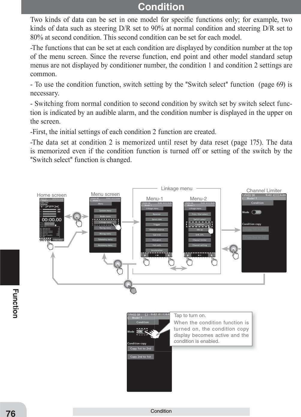
![Display condition number for a few seconds.Condition number:Background Black · Around Green:Background Black · Around RedCondition number:Background Green:Background Red On the function screen which can set the condition and the screen which can not be set, the background color of the number is different.Setting- Tap (ON) / (OFF).77FunctionCondition(Preparation)- Use the switch select function to the "Switch select". (page 69)1 (Function ON/OFF)Tap mode (ON) or (OFF) to select ON / OFF."OFF" :Function OFF"ON" :Function ONCondition copy display becomes active and the condition can be used.2 (Condition copy)Tap the condition copy direction. To copy from Condition 1 to Condition 2, tap [Copy 1 2], from Condition 2 to Condition 1, [Copy 2 1]. A confi rmation message will be displayed as "Are you sure?" Tap [Yes] to execute, or [No] to can-cel.Idle-up function adjustment3 When fi nished, return to the Linkage menu screen by pressing the HOME button.Display when using condition.](https://usermanual.wiki/Futaba/T7PX-24G.User-Manual-P41-116/User-Guide-3526469-Page-36.png)

![* The vertical cursor line moves in conjunction with the operation of the steering wheel.* The vertical cursor line moves in conjunction with the operation of the steering wheel.79Function(Preparation)-Touch the curve type and select [EXP].1 Tap the value button of the [EXP rate]. Value input buttons appear on the screen. When you want to quicken steering opera-tion, use the [+] button to adjust the + side. When you want to make steering opera-tion milder, use the [-] button to adjust the - side.If you tap "Quick" or "Mild" when the value is other than "0", Quick / Mild is reversed.To set the right and left steering curves separately, tap the rate in the direction you wish to change the setting. Value in-put buttons appear on the screen, use the [+] or [-] buttons to adjust the steering curve.(Preparation)-Touch the curve type and select [VTR].1 Tap the value button of the [VTR rate]. Value input buttons appear on the screen. When you want to quicken steering opera-tion, use the [+] button to adjust the + side. When you want to make steering opera-tion milder, use the [-] button to adjust the - side.If you tap "Quick" or "Mild" when the value is other than "0", Quick / Mild is reversed.To set the right and left steering curves separately, tap the rate in the direction you wish to change the setting. Value in-put buttons appear on the screen, use the [+] or [-] buttons to adjust the steering curve.2 Curve switching point adjustmentTap the value button of the [Point]. Value input buttons ap-pear on the screen, use the [+] or [-] buttons to move to the point you want to set.Steering EXP adjustmentSteering VTR adjustmentCurve (EXP)2 When finished, return to the Racing menu screen by pressing the HOME button twice.3 When finished, return to the Racing menu screen by pressing the HOME button twice.Adjustment buttons- Adjust with the [+] and [-] but-tons.- Return to the initial value by tapping the [reset] buttons.Adjustment buttons- Adjust with the [+] and [-] but-tons.- Return to the initial value by tapping the [reset] buttons.Curve rate -100~+100 Initial value : 0Curve rate -100~+100 Initial value : 0Point 1~99 Initial value : 50](https://usermanual.wiki/Futaba/T7PX-24G.User-Manual-P41-116/User-Guide-3526469-Page-38.png)
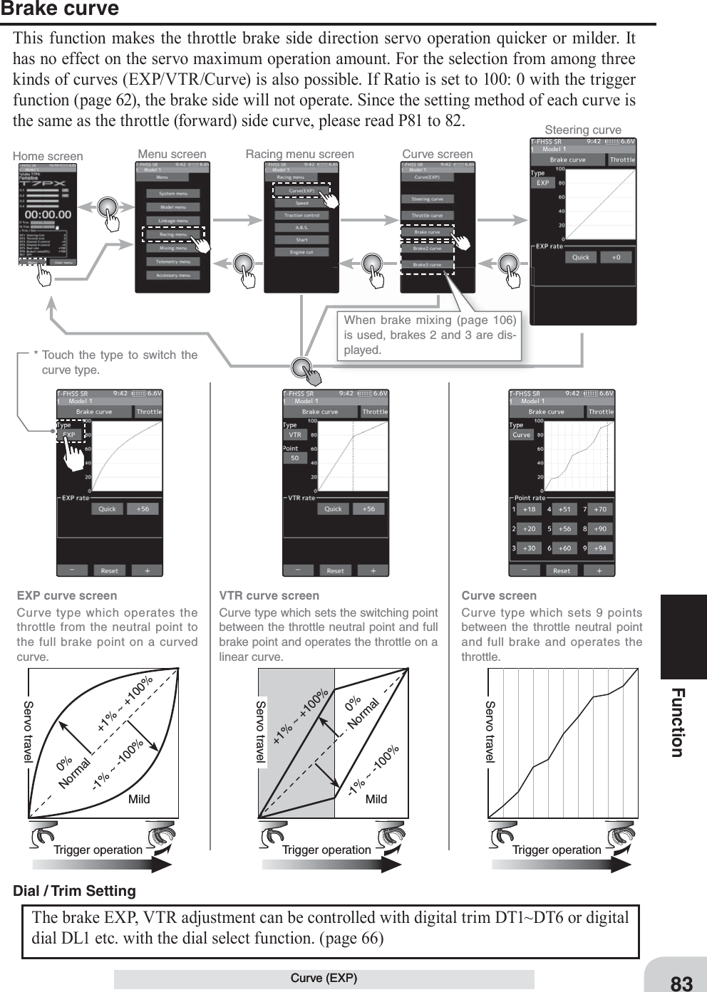
![Home screen Menu screen Racing menu screen Curve screenSteering curve* Touch the type to switch the curve type.EXP curve screenCurve type which operates the throttle from the neutral point to the high point on a curved curve.Curve screenCurve type which sets 9 points between the throttle neutral point and high point and operates the throttle.VTR curve screenCurve type which sets the switching point between the throttle neutral point and high point and operates the throttle on a linear curve.0%Normal0%Normal+1% ~ +100%+1% ~ +100%Trigger operation Trigger operation Trigger operationQuick Quick-1% ~ -100%-1% ~ -100%Mild MildServo travelServo travelServo travel80FunctionWhen the course conditions are good and the surface has good grip, set each curve to the plus [+] side (quick side). When the road surface is slippery and the drive wheels do not grip it, set each curve to the minus [-] side (mild).AdviceThrottle curve (Forward side)This function makes the throttle high side direction servo operation quicker or milder. It has no effect on the servo maximum operation amount.For the selection from among three kinds of curves (EXP/VTR/Curve) is also possible.Curve (EXP)](https://usermanual.wiki/Futaba/T7PX-24G.User-Manual-P41-116/User-Guide-3526469-Page-39.png)
![* The vertical cursor line moves in conjunction with the operation of the throttle trigger.* The vertical cursor line moves in conjunction with the operation of the throttle trigger.Adjustment buttons- Adjust with the [+] and [-] but-tons.- Return to the initial value by tapping the [reset] buttons.Curve rate -100~+100 Initial value : 0Point 1~99 Initial value : 5081FunctionCurve (EXP)(Preparation)-Touch the curve type and select [EXP].1 Tap the value button of the [EXP rate]. Value input buttons appear on the screen. When you want to quicken Throttle opera-tion, use the [+] button to adjust the + side. When you want to make Throttle operation milder, use the [-] button to adjust the - side.If you tap "Quick" or "Mild" when the value is other than "0", Quick / Mild is reversed.To set the right and left Throttle curves sep-arately, tap the rate in the direction you wish to change the setting. Value input buttons appear on the screen, use the [+] or [-] buttons to adjust the Throttl ecurve.Adjustment method for EXP curve2 When finished, return to the Racing menu screen by pressing the HOME button twice.(Preparation)-Touch the curve type and select [VTR].1 Tap the value button of the [VTR rate]. Value input buttons appear on the screen. When you want to quicken throttle opera-tion, use the [+] button to adjust the + side. When you want to make throttle operation milder, use the [-] button to adjust the - side.If you tap "Quick" or "Mild" when the value is other than "0", Quick / Mild is reversed.2 Curve switching point adjustmentTap the value button of the [Point]. Value input buttons ap-pear on the screen, use the [+] or [-] buttons to move to the point you want to set.Throttle VTR adjustment3 When finished, return to the Racing menu screen by pressing the HOME button twice.Adjustment buttons- Adjust with the [+] and [-] but-tons.- Return to the initial value by tapping the [reset] buttons.Curve rate -100~+100 Initial value : 0The throttle EXP, VTR adjustment can be controlled with digital trim DT1~DT6 or digi-tal dial DL1 etc. with the dial select function. (page 66) Dial / Trim Setting](https://usermanual.wiki/Futaba/T7PX-24G.User-Manual-P41-116/User-Guide-3526469-Page-40.png)
![* The vertical cursor line moves in conjunction with the operation of the throttle trigger.Adjustment buttons- Adjust with the [+] and [-] but-tons.- Return to the initial value by tapping the [reset] buttons.Curve rate +0~+100Point 1~9 Initial value : 1:+10/ 2:+20/ 3:+30 4:+40/ 5:+50/ 6:+60 7:+70/ 8:+80/ 9:+90ExampleP1 :3%P2 :5%P3 :10%P4 :16%P5 :20%P6 :40%P7 :55%P8 :68%P9 :80%Initial valueP1 :10%P2 :20%P3 :30%P4 :40%P5 :50%P6 :60%P7 :70%P8 :80%P9 :90%123456789Throttle curve82FunctionCurve (EXP)(Preparation)-Touch the curve type and select [Curve].1 Tap the value button of the [Point rate] (1 to 9). Value input buttons appear on the screen, use the [+] or [-] buttons to move to the point you want to set.Adjustment method for Curve2 When fi nished, return to the Racing menu screen by pressing the HOME button twice.Screen switching between throttle forward side curve and brake side curve.You can move directly without returning the throttle (forward side) curve screen and the brake curve screen to the curve screen.](https://usermanual.wiki/Futaba/T7PX-24G.User-Manual-P41-116/User-Guide-3526469-Page-41.png)
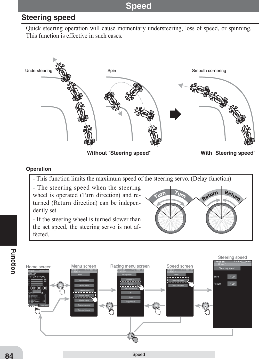
![TurnTurnReturnReturnAdjustment buttons- Adjust with the [+] and [-] but-tons.- Return to the initial value by tapping the [reset] buttons.Adjustment buttons- Adjust with the [+] and [-] but-tons.- Return to the initial value by tapping the [reset] buttons.85FunctionSpeed1 ("Turn" direction delay adjustment)Tap the value button of the [Turn]. Value in-put buttons appear on the screen. Use the [+] and [-] buttons to adjust the turn speed amount. Steering Speed adjustment2( "Return" direction adjustment)Tap the value button of the [Return]. Value input buttons appear on the screen. Use the [+] and [-] buttons to adjust the return speed amount.3 When finished, return to the Racing menu screen by pressing the HOME button twice.1001Servo operation is delayed.1001Servo operation is delayed.Speed range 1~100 Initial value : 100, there is no delay. Speed range 1~100 Initial value : 100, there is no delay. The steering speed adjustment "Tu r n" and "Return" adjustment can be controlled with digital trim DT1~DT6 or digital dial DL1 etc. with the dial select function. (page 66) Dial / Trim Setting](https://usermanual.wiki/Futaba/T7PX-24G.User-Manual-P41-116/User-Guide-3526469-Page-44.png)
![Home screen Menu screen Racing menu screen Speed screenThrottle speed1 SPEEDA delay is set over the entire throttle range.Touch [Mode] to switch between 1, 2 and 3 speed.2 SPEEDA delay can be set in 2 ranges with Point 1 as the boundary.3 SPEEDA delay can be set in 3 ranges with Point 1 and Point 2 as the boundaries.AllHigh High HighNeutral Neutral NeutralPoint 1Point 1Point 2Low range Low rangeHigh range High rangeMiddle range86FunctionSpeedThrottle speedSudden throttle trigger operation on a slippery road only causes the wheels to spin and the vehicle cannot accelerate smoothly. Setting the throttle speed function reduces wasteful bat-tery consumption while at the same time permitting smooth, enjoyable operation.With "Throttle speed"Quick start without skiddingWithout "Throttle speed"Slow start due to skidding-Throttle servo (ESC) operation is delayed so that the drive wheels will not spin even if the throttle trigger is operated more than necessary. This delay function is not performed when the throttle trigger is returned and at brake operation.-1 speed, 2 speed, or 3 speed can be selected.Operation](https://usermanual.wiki/Futaba/T7PX-24G.User-Manual-P41-116/User-Guide-3526469-Page-45.png)
![Adjustment buttons- Adjust with the [+] and [-] but-tons.- Return to the initial value by tapping the [reset] buttons.Adjustment buttons- Adjust with the [+] and [-] but-tons.- Return to the initial value by tapping the [reset] buttons.Adjustment buttons- Adjust with the [+] and [-] but-tons.- Return to the initial value by tapping the [reset] buttons.* Throttle trigger position * Throttle trigger position* Throttle trigger position87FunctionSpeed(Preparation)-Touch the speed mode and select [1].1 ("ALL" turn direction delay adjustment) Tap the [Turn] side of [All] value button. Value input buttons appear on the screen. Use the [+] and [-] buttons to adjust the turn speed amount.(Preparation)-Touch the speed mode and select [2].1 ("Low" and "High" turn direction delay adjustment) Tap the [Turn] side of [Low] or [High] value button. Value input buttons appear on the screen. Use the [+] and [-] buttons to adjust the turn speed amount.Adjustment method for 1 SpeedAdjustment method for 2 Speed2 ("ALL" return direction delay adjust-ment) Tap the [Return] side of [All] value but-ton. A warning is displayed saying "Re-turn speed will be slow. Please be careful.". If you want to use the return, tapped [Close]. Value input buttons appear on the screen. Use the [+] and [-] buttons to adjust the re-turn speed amount.3 When finished, return to the Racing menu screen by pressing the HOME button twice.1001Servo operation is delayed.1001Servo operation is delayed.1001Servo operation is delayed.Speed range 1~100 Initial value : 100, there is no delay. Speed range 1~100 Initial value : 100, there is no delay. Speed range High :1~100 Low :1~100 Initial value : 100, there is no delay.](https://usermanual.wiki/Futaba/T7PX-24G.User-Manual-P41-116/User-Guide-3526469-Page-46.png)
![Adjustment buttons- Adjust with the [+] and [-] but-tons.- Return to the initial value by tapping the [reset] buttons.Adjustment buttons- Adjust with the [+] and [-] but-tons.- Return to the initial value by tapping the [reset] buttons.* Throttle trigger position* Throttle trigger positionAdjustment buttons- Adjust with the [+] and [-] but-tons.- Return to the initial value by tapping the [reset] buttons.* Throttle trigger position88FunctionSpeed2 ("Low" and "High" return direction delay adjustment) Tap the [Return] side of [Low] or [High] value button. A warning is displayed saying "Return speed will be slow. Please be careful.". If you want to use the return, tapped [Close]. Value input buttons appear on the screen. Use the [+] and [-] buttons to adjust the return speed amount.3 (Speed switching point adjustment)When you want to change the "Low" and "High" switching point, tap the [point 1] value button. Value input buttons appear on the screen, use the [+] or [-] buttons to move to the point you want to set.4 When finished, return to the Racing menu screen by pressing the HOME button twice.1001Servo operation is delayed.Speed range High :1~100 Low :1~100 Initial value : 100, there is no delay. Point Point 1 :1~100 Initial value : 30(Preparation)-Touch the speed mode and select [3].1 ( "Low", "Middle", or "High" turn direction delay adjustment) Tap the [Turn] side of [Low] or [High] value button. Value input buttons appear on the screen. Use the [+] and [-] buttons to adjust the turn speed amount.Adjustment method for 2 Speed1001Servo operation is delayed.Speed range High :1~100 Middle :1~100 Low :1~100 Initial value : 100, there is no delay.](https://usermanual.wiki/Futaba/T7PX-24G.User-Manual-P41-116/User-Guide-3526469-Page-47.png)
![Adjustment buttons- Adjust with the [+] and [-] but-tons.- Return to the initial value by tapping the [reset] buttons.Adjustment buttons- Adjust with the [+] and [-] but-tons.- Return to the initial value by tapping the [reset] buttons.* Throttle trigger position* Throttle trigger positionWarningSetting the speed function in the return direction slows the deceleration of the car body, so please be careful to set it carefully.89FunctionSpeed2 ("Low", Middle", and "High" return direction delay adjustment) Tap the [Return] side of [Low], [Middle] or [High] value button. A warning is displayed saying "Return speed will be slow. Please be careful.". If you want to use the return, tapped [Close]. Value input buttons appear on the screen. Use the [+] and [-] buttons to adjust the return speed amount.3 (Speed switching point adjustment)When you want to change the "Low", "Middle" and "High" switching point, tap the [point 1] or [point 2] value button. Value in-put buttons appear on the screen, use the [+] or [-] buttons to move to the point you want to set.1001Servo operation is delayed.Point Point 1 :1~100 Point 1 :2~100 Initial value : 30Speed range High :1~100 Middle :1~100 Low :1~100 Initial value : 100, there is no delay. 4 When finished, return to the Racing menu screen by pressing the HOME button twice.The throttle speed adjustment "Tu r n" and "Return" adjustment can be controlled with digital trim DT1~DT6 or digital dial DL1 etc. with the dial select function. (page 66) Dial / Trim Setting](https://usermanual.wiki/Futaba/T7PX-24G.User-Manual-P41-116/User-Guide-3526469-Page-48.png)
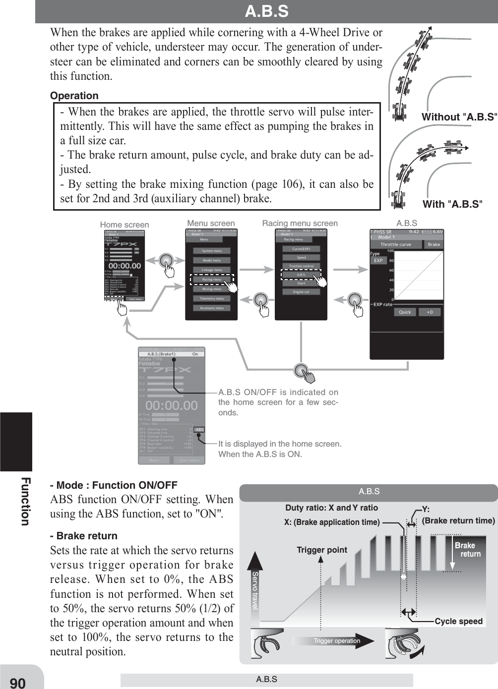
![Brake return(Amount of brake return)Brake returnServo travel* Displays ON/OFF of the con-dition that ABS is working by throttle trigger operation. The amount of brake return var-ies depending on the curve set-ting of the brake etc.Adjustment buttons- Adjust with the [+] and [-] but-tons.- Return to the initial value by tapping the [reset] buttons.91FunctionA.B.S- DelaySets the delay from brake operation to ABS operation. When set to 0%, the ABS func-tion is activated without any delay. At 50%, the ABS function is activated after a delay of approximately 0.7 seconds and at 100%, the ABS function is activated after a delay of ap-proximately 1.4 seconds.- Cycle speedSets the pulse speed (cycle speed). The smaller the set value, the faster the pulse cycle.- Duty ratioSets the proportion of the time the brakes are applied and the time the brakes are released by pulse operation. The ratio can be set to +3 ~ 0 ~ -3 in 7 steps.- Trigger pointSets the trigger point at which the ABS function begins to operate at brake operation.When trigger ratio (page 62) was set to 100:0, brake operation stops, and the servo does not operate even if the ABS function is set.When trigger ratio was set to 100:01 (Function ON/OFF)Tap "Brake" (ON) or (OFF) to select ON / OFF."OFF" :ABS function OFF"ON" :ABS function ONWhen using ABS function ON/OFF by switch, use the switch select function (page 69) to set the switch to be used.A.B.S. function adjustment2 ("Brake return" amount adjustment)Tap the value button of the [Brake return]. Value input buttons appear on the screen. Use the [+] and [-] buttons to adjust the return amount."0" :No return"50" :Return to the 50% position of the brake operation amount"100" :Return to the neutral position.Return amount 0 ~ 50 ~ 100 Initial value: 50](https://usermanual.wiki/Futaba/T7PX-24G.User-Manual-P41-116/User-Guide-3526469-Page-50.png)
![Adjustment buttons- Adjust with the [+] and [-] but-tons.- Return to the initial value by tapping the [reset] buttons.Adjustment buttons- Adjust with the [+] and [-] but-tons.- Return to the initial value by tapping the [reset] buttons.Adjustment buttons- Adjust with the [+] and [-] but-tons.- Return to the initial value by tapping the [reset] buttons.Cycle speedServo travelCycleDuty ratioServo travelDuty ratio: X and Y ratioX: (Brake application time)Y: (Brake return time92FunctionA.B.S3 ("Delay" amount setup)Tap the value button of the [Delay]. Value input buttons appear on the screen. Use the [+] and [-] buttons to adjust the delay amount."0" :A.B.S. function performed without any delay"50" :A.B.S. function performed after an approximate 0.5 sec delay."100" :A.B.S. function performed after an approximate 1.0 sec delay.4 ("Cycle speed" adjustment)Tap the value button of the [Cycle speed]. Value input buttons appear on the screen. Use the [+] and [-] buttons to adjust the cycle speed amount.- The smaller the set value, the faster the pulse speed.5 ("Duty ratio" setup)Tap the value button of the [Duty ratio]. Value input buttons appear on the screen. Use the [+] and [-] buttons to adjust the duty ratio amount."-4" :Brake application time becomes shortest. (Brakes lock with difficulty)"+4" :Brake application time becomes longest (Brakes lock easily)Delay amount 0~ 100 Initial value: 0Cycle speed amount 1~ 100 Initial value: 30Duty ratio amount -4~ +0~ +4 Initial value: +0](https://usermanual.wiki/Futaba/T7PX-24G.User-Manual-P41-116/User-Guide-3526469-Page-51.png)
![Adjustment buttons- Adjust with the [+] and [-] but-tons.- Return to the initial value by tapping the [reset] buttons.Trigger pointServo travelTrigger pointTrigger pointBrake sideNeutral* Throttle trigger positionBrake mixingBrake 2 "ON"Brake mixingBrake 3 "ON"Brake mixingBrake 2&3 "ON"93FunctionA.B.STrigger point 5~ 95 Initial value: 306 ("Trigger point" setup)Tap the value button of the [Trigger point]. Value input buttons appear on the screen. Use the [+] and [-] buttons to adjust the operation point.- Sets the throttle trigger position at which the A.B.S. function is performed. The number is the % display with the full brake position made 100.Tap [Normal] or [Reverse] to set the operating range."Normal": Neutral to trigger point is the range of motion."Reverse": The range from the trigger point to the full brake side is the oper-ating range.7 When finished, return to the Racing menu screen by pressing the HOME button.ABS can be independently set for the brakes which are controlled by the Brake2 and Brake3 (3rd CH and 4th CH). Brake mixing can be set under the mixing menu. (page 106) 1/5 scale car and other independent brakes and ABSBrake 1, 2, 3 can be adjusted independently except the trigger point of the setting item.](https://usermanual.wiki/Futaba/T7PX-24G.User-Manual-P41-116/User-Guide-3526469-Page-52.png)
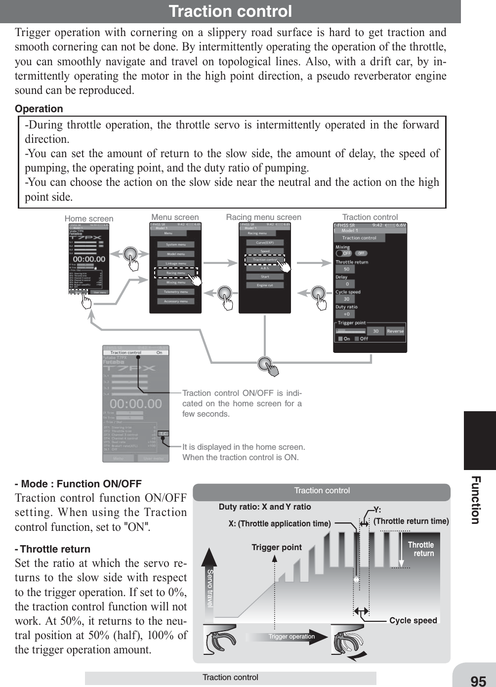
![Throttle return(Amount of throttle return)Throttle returnServo travel* Displays ON/OFF of the condi-tion that Traction control is work-ing by throttle trigger operation. The amount of throttle return varies depending on the curve setting of the throttle etc.Adjustment buttons- Adjust with the [+] and [-] but-tons.- Return to the initial value by tapping the [reset] buttons.96FunctionTraction control- DelaySet the delay from when the throttle is operated until when the traction control operation starts. When set to 0%, the traction control function works without delay. At 50%, the trac-tion control function works approximately 0.5 second later, and the traction control function works about 1.0 second later at 100%.- Cycle speedSets the pulse speed (cycle speed). The smaller the set value, the faster the pulse cycle.- Duty ratioSet the ratio of the time to operate to the high side and the time to operate to the slow side in the pumping operation.The ratio can be set to +4 ~ +0 ~ -4 in 9 steps.- Trigger pointIn the throttle operation, set the position of the trigger at which traction control starts to work. Normal / Reverse, reverse the throttle operation range where the traction control op-erates, with the trigger point as the boundary.1 (Function ON/OFF)Tap "Mixing" (ON) or (OFF) to select ON / OFF."OFF" :Traction control function OFF"ON" :Traction control function ONWhen using Traction control function ON/OFF by switch, use the switch select func-tion (page 69) to set the switch to be used.Traction control function adjustment2 ("Throttle return" amount adjustment)Tap the value button of the [Brake return]. Value input buttons appear on the screen. Use the [+] and [-] buttons to adjust the return amount."0" :No return"50" :Return to the 50% position of the brake operation amount"100" :Return to the neutral position.Return amount 0 ~ 50 ~ 100 Initial value: 50](https://usermanual.wiki/Futaba/T7PX-24G.User-Manual-P41-116/User-Guide-3526469-Page-55.png)
![Adjustment buttons- Adjust with the [+] and [-] but-tons.- Return to the initial value by tapping the [reset] buttons.Adjustment buttons- Adjust with the [+] and [-] but-tons.- Return to the initial value by tapping the [reset] buttons.Adjustment buttons- Adjust with the [+] and [-] but-tons.- Return to the initial value by tapping the [reset] buttons.Cycle speedServo travelCycleDuty ratioServo travelDuty ratio: X and Y ratioX: (Brake application time)Y: (Brake return time97FunctionTraction control3 ("Delay" amount setup)Tap the value button of the [Delay]. Value input buttons appear on the screen. Use the [+] and [-] buttons to adjust the delay amount."0" :Function performed without any delay"50" :Function performed after an approximate 0.5 sec delay."100" :Function performed after an approximate 1.0 sec delay.4 ("Cycle speed" adjustment)Tap the value button of the [Cycle speed]. Value input buttons appear on the screen. Use the [+] and [-] buttons to adjust the cycle speed amount.- The smaller the set value, the faster the pulse speed.5 ("Duty ratio" setup)Tap the value button of the [Duty ratio]. Value input buttons appear on the screen. Use the [+] and [-] buttons to adjust the duty ratio amount."-4" :Brake application time becomes shortest. (Brakes lock with difficulty)"+4" :Brake application time becomes longest (Brakes lock easily)Delay amount 0~ 100 Initial value: 0Cycle speed amount 1~ 100 Initial value: 30Duty ratio amount -4~ +0~ +4 Initial value: +0](https://usermanual.wiki/Futaba/T7PX-24G.User-Manual-P41-116/User-Guide-3526469-Page-56.png)
![Adjustment buttons- Adjust with the [+] and [-] but-tons.- Return to the initial value by tapping the [reset] buttons.* Throttle trigger positionServo travelTrigger pointReverse directionNeutral NormaldirectionHighTrigger pointTrigger point98FunctionTraction controlTrigger point 5~ 95 Initial value: 306 ("Trigger point" setup)Tap the value button of the [Trigger point]. Value input buttons appear on the screen. Use the [+] and [-] buttons to adjust the operation point.- Sets the throttle trigger position at which the traction control function is performed. The number is the % display with the full brake position made 100.Tap [Normal] or [Reverse] to set the operating range."Normal": High range from the trigger point to the operating range."Reverse": Operating range from neutral to trigger point.7 When finished, return to the Racing menu screen by pressing the HOME button.Use PS1 to 6 to switch the traction control function ON/OFF.See the switch select function. (page 69)Switch settingThe throttle return amount, delay amount and cycle speed can be controlled with digital trim DT1~DT6 or digital dial DL1 etc. with the dial select function. (page66) Dial / Trim Setting](https://usermanual.wiki/Futaba/T7PX-24G.User-Manual-P41-116/User-Guide-3526469-Page-57.png)
![* The status display changes to "Ready".Home screen Menu screen Racing menu screen Start 99FunctionStartStart If the track is slippery and you begin to accelerate by pushing the trigger to full throttle, the car wheels will spin and the car will not accelerate smoothly. When the Start function is activated, merely operating the throttle trigger slowly causes the throttle servo to automati-cally switch from the set throttle position to a preset point so that the tires do not lose their grip and the car accelerates smoothly. - When the throttle trigger is moved to the preset position (trigger point), the throttle servo moves to the preset position. - When the throttle trigger is operated slowly so that the wheels will not spin, the car au-tomatically accelerates to the set speed. - This function is effective only for the ¿rst throttle trigger operation at starting. This function has to be activated before every start. - When the throttle trigger is returned slightly, the Start function is automatically deacti-vated and the set returns to normal throttle trigger operation. Operation With "Throttle speed"Quick start without skiddingWithout "Throttle speed"Slow start due to skidding1 (Function ON/OFF)Tap "Mode" (ON) or (OFF) to select ON / OFF."OFF" :Start function OFF"ON" :Start function ONThe status display changes to [Ready].To enable the [Ready] status with the switch, set the "Start switch" with the switch select function (page 69).Start function adjustment Setting- Tap (ON) / (OFF).](https://usermanual.wiki/Futaba/T7PX-24G.User-Manual-P41-116/User-Guide-3526469-Page-58.png)
![100FunctionStart2 ("Trigger point" setup)Tap the value button of the [Trigger point]. Value input buttons appear on the screen. Use the [+] and [-] buttons to adjust the op-eration point.3 ("Preset position" setup)Tap the value button of the [Preset]. Value input buttons appear on the screen. Use the [+] and [-] buttons to set the preset po-sition of the throttle servo.Adjustment buttons- Adjust with the [+] and [-] but-tons.- Return to the initial value by tapping the [reset] buttons.Trigger point 5~ 95 Initial value: 30Restart Tap [OFF] to [Ready]Adjust button Adjust with the [+] and [-] but-tons.- Return to the initial value by tapping the [reset] buttons.Preset position 0~100 Initial value: 04 ("Ready" setting)To set "Ready" again, touch [OFF] of "Sta-tus", the display will change to [Ready] and wait for trigger operation. In addition, you can set the switch to be in the [Ready] state in the switch select function (page 69).5 When finished, return to the Racing menu screen by pressing the HOME button.In the [Ready] state, if the throttle trigger is operated to the position of the trigger posi-tion, the throttle servo moves to the servo operation position set with preset. It is can-celed when the throttle trigger is returned.](https://usermanual.wiki/Futaba/T7PX-24G.User-Manual-P41-116/User-Guide-3526469-Page-59.png)
![Home screen Menu screen Racing menu screen Start Warning displayIf the power switch is turned on while the engine cut switch is on, an audible alarm will be heard. Immediately set the engine cut switch to OFF. Engine cut ON/OFF is indicated on the home screen for a few seconds. It is displayed in the home screen, when the engine cut is ON.101FunctionEngine CutEngine CutWhen the switch is pressed, the throttle servo will move to the preset position without re-gard to the throttle trigger position. This is convenient when used to cut the engine of boats, etc. (The switch select function. See page 69)(Preparation)- Use the switch select function to the "Switch select". (page 69) When the switch is not set "A switch is not assigned" is displayed. Tap [Switch select] to display the switch selection screen and set the switch.Engine Cut function adjustmentWhen trigger ratio (page 62) is set to 100: 0, the brake side function will not operate. The preset position set here is the linkage reference. Set the linkage so that the carbure-tor is fully closed in the preset adjustment range and the engine stops. Full throttle posi-tion is set by “advance” of the end point function. Adjust the idling position with throttle trim.When trigger ratio was set to 100:0](https://usermanual.wiki/Futaba/T7PX-24G.User-Manual-P41-116/User-Guide-3526469-Page-60.png)
![*Shows the ON/OFF stateCautionAlways operate carefully before using this function.While push switch PS1 to PS6, or trigger switch TS with preset function set is in the ON state, the servo (mo-tor controller) is locked in the preset position and does not operate even if the throttle trigger is operated. If the servo was operated at the wrong setting, you may lose control of the car (boat).102FunctionEngine Cut1 (Preset position setup) Tap the value button of the [Preset]. Value input buttons appear on the screen. Use the [+] and [-] buttons to set the preset position of the throttle servo.2 When finished, return to the Linkage menu screen by pressing the HOME button.Adjust button Adjust with the [+] and [-] but-tons.- Return to the initial value by tapping the [reset] buttons.Preset position 0~100 Initial value: 0The function select dial function can control the engine cut preset position with digital dial or digital trim (page 66). Dial / Trim Setting The throttle servo operating position (preset position) set by this setting is unrelated to the setting of other functions. Maximum to minimum servo travel can be set. However, the reverse function setting is enabled.](https://usermanual.wiki/Futaba/T7PX-24G.User-Manual-P41-116/User-Guide-3526469-Page-61.png)

![104FunctionSteering Mixing2 (Channel setup)The channel list screen used for steering 2 is displayed. Tap the auxiliary channel that con-nected the servo of steering 2.- When all channels are in use, a screen saying "No assignable channel" is displayed, please turn off other mixing and make an unused channel. You can check the mixing used on the channel setting screen (page 75).- T7PX can also be used for steering 2 by setting the throttle to another auxiliary channels setting function (P75) and making Ch.2 assignable channel (page 75).3 (Steering 1 servo steering angle adjustment)Tap the value button of the "Steering 1" [Left] or [Right]. Value input buttons appear on the screen. Turn the steering wheel fully to the left or right and adjust the left and right steering amounts by [+] or [-] button.4 (Steering 2 servo steering angle adjustment) Tap the value button of the "Steering 2" [Left] or [Right]. Value input buttons appear on the screen. Turn the steering wheel fully to the left or right and adjust the left and right steering amounts by [+] or [-] button.For S-FHSS (analog) system, 1 to 7 chan-nels are displayed.If there is no assignable channel, tap [Close]. Turn off other mixing and make assignable channels.To set the throttle to another auxiliary channel and use it for steering 2, tap [Yes]. To cancel, [No] is tapped.Adjustment buttons- Adjust with the [+] and [-] but-tons.- Return to the initial value by tapping the [reset] buttons.Adjustment buttons- Adjust with the [+] and [-] but-tons.- Return to the initial value by tapping the [reset] buttons.Steering 1 rate (Left/Right) 0~140 Initial value : 100Steering 2 rate (Left/Right) 0~140 Initial value : 100](https://usermanual.wiki/Futaba/T7PX-24G.User-Manual-P41-116/User-Guide-3526469-Page-63.png)
![*Shows the ON/OFF state105FunctionSteering Mixing5 (Steering mixing rate adjustment) Tap the value button of the "Steering mixing rate" [Left] or [Right]. Value input buttons appear on the screen, adjust each of the left/right steering angles using the [+] or [-] button.6 (Ackerman adjustment)Tap the value button of the "Ackerman rate". Value input buttons appear on the screen, adjust the left and right differential amount and adjust the ackerman by [+] and [-] button.7 (Steering brake)(Preparations)When using this function, set the switch with the "Switch select" function (page 69). Tap the value button of the "Brake rate". Value input buttons appear on the screen, adjust the steering 1/2 operation position by [+] and [-] button.Adjustment buttons- Adjust with the [+] and [-] but-tons.- Return to the initial value by tapping the [reset] buttons.Adjustment buttons- Adjust with the [+] and [-] but-tons.- Return to the initial value by tapping the [reset] buttons.Adjustment buttons- Adjust with the [+] and [-] but-tons.- Return to the initial value by tapping the [reset] buttons.Steering mix rate 0~100 Initial value : 100Steering mix rate -100~+0~+100 Initial value : +0Brake mix rate -100~+0~+100 Initial value : +0The ackerman rate adjustment can be controlled with digital trim DT1~DT6 or digital dial DL1 etc. with the dial select function. (page 66) Dial / Trim Setting 8 When finished, return to the Racing menu screen by pressing the HOME button twice.](https://usermanual.wiki/Futaba/T7PX-24G.User-Manual-P41-116/User-Guide-3526469-Page-64.png)


![108FunctionBrake Mixing2 (Channel setup)The channel list screen used for brake 2 or brake 3 is displayed. Tap the auxiliary channel that connected the servo of brake 2 or brake 3.- When all channels are in use, a screen saying "No assignable channel" is displayed, please turn off other mixing and make an unused channel. You can check the mixing used on the channel setting screen (page 75).- T7PX can also be used for brake 2 or 3 by setting the steering to another auxiliary channels with the channel setting function (P75) and making Ch.1 assignable channel (page 75).For S-FHSS (analog) system, 1 to 7 chan-nels are displayed.If there is no assignable channel, tap [Close]. Turn off other mixing and make assignable channels.To set the steering to another auxiliary channel and use it for brake 2 or 3, tap [Yes]. To cancel, [No] is tapped.3 (Brake 2 & 3 rate)Tap the value button of the "Brake 2 or 3" [Brake rate]. Value input buttons appear on the screen, use the [+] and [-] buttons to adjust the brake rate amount.- When adjusting the brake amount of both brakes after individually adjusting the Brake2 and Brake3, select “Brake2,3 rate”.- The brake 1 rate is linked with throttle channel (ATL) setting.4 (Delay amount setup)Tap the value button of the "Brake 1 or 2,3" [Brake delay]. Value input buttons appear on the screen, use the [+] and [-] buttons to adjust the delay amount.- Since a delay at all the brakes is dangerous, a delay is not applied to the brake to be adjusted last. For example, when brakes 1, 2, and 3 are all used, when a delay is applied to brakes 2 and 3, a delay cannot be applied to brake 1. When a delay must be applied to brake 1, the brake 2 or brake 3 delay must be set to “0”.Adjustment buttons- Adjust with the [+] and [-] but-tons.- Return to the initial value by tapping the [reset] buttons.Brake rate 0 ~ 100 Initial value:100](https://usermanual.wiki/Futaba/T7PX-24G.User-Manual-P41-116/User-Guide-3526469-Page-67.png)
![109FunctionBrake Mixing5 (Steering mixing)Use this function when you want to weaken the brakes when steering was operated.Tap the value button of the "Brake 1 or 2,3" [Left]. Value input buttons appear on the screen. use the [+] and [-] buttons to adjust the rake amount.Tap the value button of the "Brake 1 or 2,3"[Right]. Value input buttons appear on the screen. use the [+] and [-] buttons to adjust the rake amount. The smaller the value, the weaker the front brakes. Set value "100" is the state in which steering mixing is not performed.- The mixing amount can be adjusted in a range from 0 to 100.6 When finished, return to the Mixing menu screen by pressing the HOME button twice.Adjustment buttons- Adjust with the [+] and [-] but-tons.- Return to the initial value by tapping the [reset] buttons.Brake rate (Mixung ) 100~0 Initial value:100The dial select function can control the brake 1,2,3 rate , delay amount and EXP setting using digital dial or digital trim. (page 66) Dial / Trim Setting](https://usermanual.wiki/Futaba/T7PX-24G.User-Manual-P41-116/User-Guide-3526469-Page-68.png)

![111FunctionGyro Mixing(Preparation)- Refer to the gyro instruction manual and connect the gyro to the receiver. When using remote gain, connect gyro sensitivity adjustment to the auxiliary channels of the receiver.- When using gyro mixing by switching between the NORM (normal) and AVCS modes, use the switch select function (page 69) to set the switch to be used.Gyro mixing adjustment1 (Function ON/OFF)Tap "Mixing" (ON) or (OFF) to select ON / OFF."OFF" :Mixing function OFF"ON" :Mixing function ON2 (Channel setup)The channel list screen used for the gain steering channel is displayed. Tap the auxiliary channel that connected the gain steering channel.- When all channels are in use, a screen saying "No assignable channel" is displayed, please turn off other mixing and make an unused channel. You can check the mixing used on the channel setting screen (page 75).For S-FHSS (analog) system, 1 to 7 chan-nels are displayed.If there is no assignable channel, tap [Close]. Turn off other mixing and make assignable channels.Setting- Tap (ON) / (OFF).](https://usermanual.wiki/Futaba/T7PX-24G.User-Manual-P41-116/User-Guide-3526469-Page-70.png)
![Can be switch the group with the group change switch. When changing the gain with the switch, indicated on the home screen for a few sec-onds.* Display the current gyro gain.112FunctionGyro Mixing3 (Gyro mixing type selection)Touch the Gyro type and select [1 gain], [2 gain] or [4 gain]."1 gain" :One mode only"2 gain" :Switching Gyro gain 1 and Gyro gain 2"4 gain" :Set 4 Gyro gains.2 groups of 2 gains can be set in one group.Set the switch to change the group and the switch to change the gain in the group. (Use to 2 switch)4 (Gyro gain adjustment)Tap the value button of each the [Gain]. Val-ue input buttons appear on the screen, use the [+] and [-] buttons to adjust the brake rate amount.5 When fi nished, return to the Mixing menu screen by pressing the HOME button twice.The gain amount can be adjusted by using the dial select function. (page 66) Dial / Trim Setting Setting- Tap Gain type. 1 gain/ 2 gain/ 4 gainAdjustment buttons- Adjust with the [+] and [-] but-tons.- Return to the initial value by tapping the [reset] buttons.Gyro gain AVCS120~0~Normal120 Initial value:50](https://usermanual.wiki/Futaba/T7PX-24G.User-Manual-P41-116/User-Guide-3526469-Page-71.png)
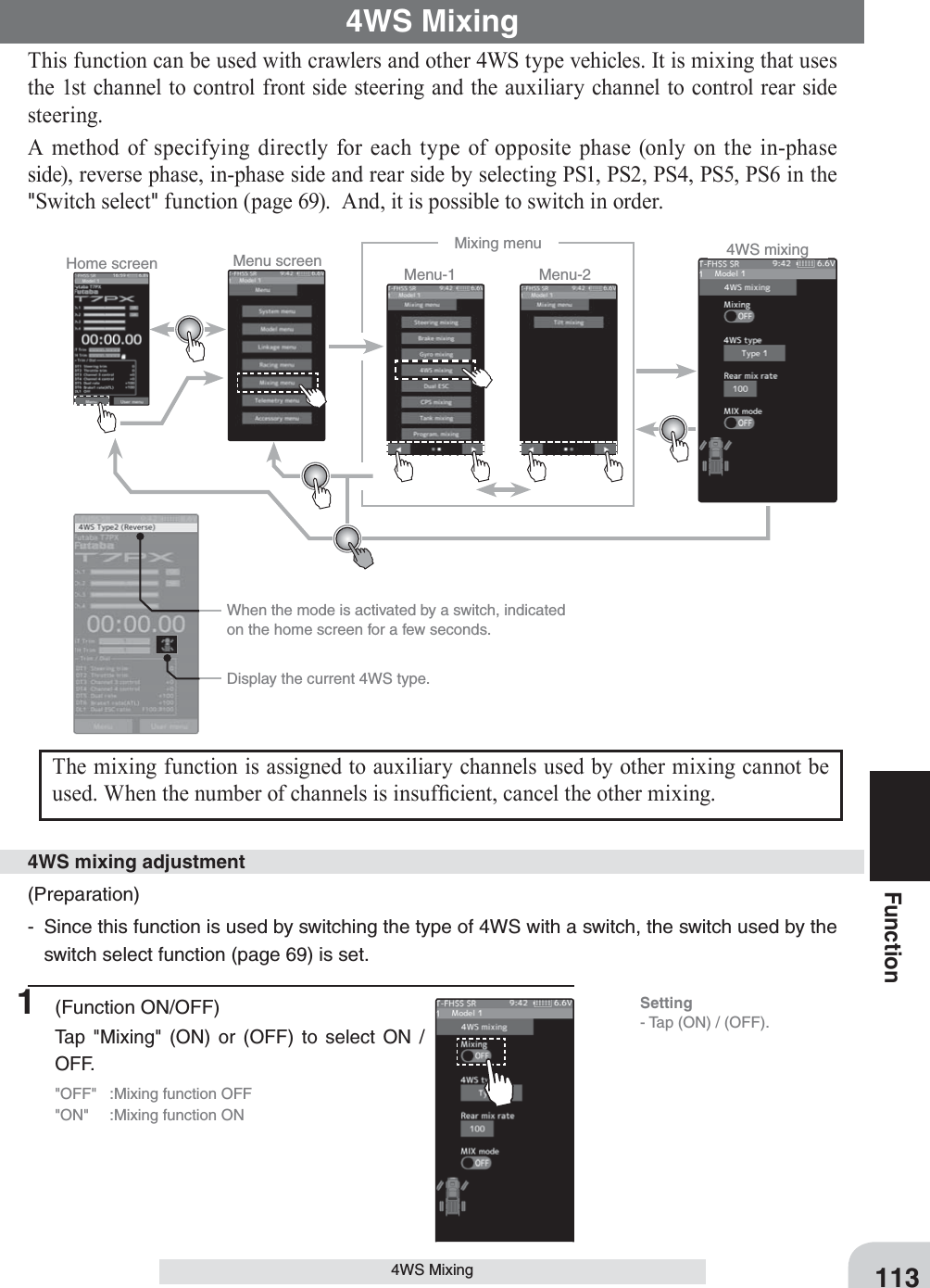
![Type2 Front side only, Reverse phase switchingType3 Front side only, Reverse phase and same phase switchingType4 Front side only, reverse phase, same phase, and rear side only switching114Function4WS Mixing2 (Channel setup)The channel list screen used for rear steering is displayed. Tap the auxiliary channel that connected the servo of rear steering.- When all channels are in use, a screen saying "No assignable channel" is displayed, please turn off other mixing and make an unused channel. You can check the mixing used on the channel setting screen (page 75).- T7PX can also be used for rear steering by setting the throttle to another auxiliary channels setting function (P75) and making Ch.2 assignable channel (page 75).3 (4WS type selection)Touch the 4WS type and select [Type 1], [Type 2], [Type 3]or [Type 4]."Type1" :Function OFF (front only)"Type2" :Front side only, reverse phase switching"Type3" :Front side only, reverse phase and same phase switching"Type4" :Front side only, reverse phase, same phase, and rear side only switchingSwitched in the order shown in the fi gure below by set SWFor S-FHSS (analog) system, 1 to 7 chan-nels are displayed.If there is no assignable channel, tap [Close]. Turn off other mixing and make assignable channels.To set the throttle to another auxiliary channel and use it for steering 2, tap [Yes]. To cancel, [No] is tapped.Setting- Tap T4WS type. Type 1/ Type 2/ Type3/ Type 4](https://usermanual.wiki/Futaba/T7PX-24G.User-Manual-P41-116/User-Guide-3526469-Page-73.png)
![115Function4WS Mixing4 (Rear side travel adjustment)Tap the value button of the [Rear mix rate]. Value input buttons appear on the screen, use the [+] and [-] buttons to adjust the rear side travel amount.5 (Mix mode setting)Tap "MIX mode" (ON) or (OFF) to select ON / OFF."OFF" :The EXP function of the 1st CH and other settings are not mixed."ON" :The EXP function of the 1st CH and other settings are mixed.6 When finished, return to the Mixing menu screen by pressing the HOME button twice.The mixing amount can be adjusted by using the dial select function. (page 66) Dial / Trim Setting Adjustment buttons- Adjust with the [+] and [-] but-tons.- Return to the initial value by tapping the [reset] buttons.Rear rate (Rear mix rate) 0~100 Initial value:100Setting- Tap (ON) / (OFF).](https://usermanual.wiki/Futaba/T7PX-24G.User-Manual-P41-116/User-Guide-3526469-Page-74.png)
![117FunctionDual ESC2 (Channel setup)The channel list screen used for the front ESC channel is displayed. Tap the auxiliary chan-nel that connected the front ESC channel.- When all channels are in use, a screen saying "No assignable channel" is displayed, please turn off other mixing and make an unused channel. You can check the mixing used on the channel setting screen (page 75).For S-FHSS (analog) system, 1 to 7 chan-nels are displayed.If there is no assignable channel, tap [Close]. Turn off other mixing and make assignable channels.3 (Drive ratio adjustment)Adjust the front and rear motor controller operation amount by or button. The button increases and the button de-creases the rear ratio.Both the front and rear ratios become 100%4 (Mix mode setting)Tap "MIX mode" (ON) or (OFF) to select ON / OFF."OFF" :The EXP function of the 2nd CH and other settings are not mixed."ON" :The EXP function of the 2nd CH and other settings are mixed.5 (Trim mode setup)Tap "Trim mode" (ON) or (OFF) to select ON / OFF."OFF" :The trim of the 2nd CH is not mixed."ON" :The trim of the 2nd CH is mixed.6 When fi nished, return to the Mixing menu screen by pressing the HOME button twice.Adjustment buttons- Adjust with the and buttons.- Return to the initial value by tapping the [reset] buttons.Rear rate (Rear mix rate) 0~100 Initial value:100Setting- Tap (ON) / (OFF).Setting- Tap (ON) / (OFF).The dial select function can control the drive ratio with digital dial or digital trim.(page 66) Dial / Trim Setting As this function drives 2 separate motor controllers simultaneously, a mutual load is ap-plied. Use this function carefully so that the motor controllers are not damaged.Futaba will not be responsible for motor controller, motor, and other vehicle trouble due to use of this function.Note:](https://usermanual.wiki/Futaba/T7PX-24G.User-Manual-P41-116/User-Guide-3526469-Page-76.png)