Contents
- 1. User Manual (P1-40)
- 2. User Manual (P41-116)
- 3. User Manual (P116-192)
User Manual (P1-40)

2
Thank you for purchasing a Futaba 7PX-2.4GHz system.
Before use, read this manual carefully in order to use it safely.
After reading this manual, store it in a safe place.
IN NORTH AMERICA
Please feel free to contact the Futaba Service Center for assistance with operation and programming. Please
be sure to regularly visit the 7PX Frequently Asked Questions web site at www.futaba-rc.com/faq/. This page
includes extensive programming, use, set up and safety information on the 7PX radio system and is updated
regularly. Any technical updates and US manual corrections will be available on this web page. If you do not
¿nd the answers to your questions there, please see the end of our F.A.Q. area for information on contacting us
via e-mail for the most rapid and convenient response.
Don’t you have Internet access? Internet access is available at no charge at most public libraries, schools, and
other public resources. :e ¿nd internet support to be a fabulous reference for many modelers as items can be
printed and saved for future reference, and can be accessed at any hour of the day, night, weekend or holiday. If
you do not wish to access the internet for information, however, don’t worry. Our support teams are available
Monday through Friday 8-5 Central time to assist you.
$SSOLFDWLRQ([SRUWDQG0RGL¿FDWLRQ
1. This product may be used for models only. It is not intended for use in any application other than the control
of models for hobby and recreational purposes.
2. Exportation precautions:
(a) When this product is exported from the country of manufacture, its use is to be approved by the laws gov-
erning the country of destination for devices that emit radio frequencies. If this product is then re-exported to
other countries, it may be subject to restrictions on such export. Prior approval of the appropriate government
authorities may be required. If you have purchased this product from an exporter outside your country, and not
the authorized Futaba distributor in your country, please contact the seller immediately to determine if such
export regulations have been met.
(b) Use of this product with other than models may be restricted by Export and Trade Control Regulations, and
an application for export approval must be submitted.
. Modi¿cation, adjustment, and replacement of parts: Futaba is not responsible for unauthorized modi¿cation,
adjustment, and replacement of parts on this product. Any such changes may void the warranty.
OUTSIDE NORTH AMERICA
Please contact the Futaba importer in your region of the world to assist you with any questions, problems or
service needs. Please recognize that all information in this manual, and all support availability, is based upon
the systems sold in North America only. Products purchased elsewhere may vary. Always contact your region’s
support center for assistance.
FOR SERVICE ONLY:
Futaba Service Center
3002 N. Apollo Drive, Suite 1
Champaign, IL 61822
Phone: 217-398-0007
www.futaba-rc.com/service.html
E-mail: futabaservice@hobbico.com
FOR SUPPORT :
(PROGRAMMING AND USER QUESTIONS)
Please start here for answers to most questions:
www.futaba-rc.com/faq/
Fax: 217-398-7721
Phone: 217-398-8970 option 2

3
• No part of this manual may be reproduced in any form without prior permission.
• The contents of this manual are subject to change without prior notice.
• This manual has been carefully written. Please write to Futaba if you feel that any corrections or clari¿cations
should be made.
• Futaba is not responsible for the use of this product.
Compliance Information Statement (for U.S.A.)
This device complies with part 15 of the FCC Rules. Operation is subject to the following two conditions:
(1) This device may not cause harmful interference, and (2) This device must accept any interference received,
including interference that may cause undesired operation.
RF Radiation Exposure Statement
This equipment complies with FCC radiation exposure limits set forth for an uncontrolled environment.
This transmitter must not be co-located or operating in conjunction with any other antenna or transmitter.
The responsible party for the compliance of this device is:
Futaba Service Center
3002 N Apollo Drive Suite 1, Champaign, IL 61822 U.S.A.
TEL (217)398-8970 or E-mail: support@hobbico.com (Support)
TEL (217)398-0007 or E-mail: futabaservice@hobbico.com (Service)
IC
This device complies with Industry Canada license-exempt RSS standard(s). Operation is subject to the follow-
ing two conditions:
(1) this device may not cause interference, and (2) this device must accept any interference, including interfer-
ence that may cause undesired operation of the device.
This equipment complies with IC radiation exposure limits set forth for an uncontrolled environment. This
transmitter must not be colocated or operating in conjunction with any other antenna or transmitter.
French:
Cet appareil radio est conforme au CNR d’Industrie Canada. L’utilisation de ce dispositif est autorisée seule-
ment aux deux conditions suivantes : (1) il ne doit pas produire de brouillage, et (2) l’utilisateur du dispositif
doit être prêt à accepter tout brouillage radioélectrique reçu, même si ce brouillage est susceptible de compro-
mettre le fonctionnement du dispositif.
Cet équipement est conforme aux limites d'exposition au rayonnement du CI établies pour un environnement
non contrôlé. Cet émetteur ne doit pas être co-situé ou fonctionner conjointement avec une autre antenne ou
émetteur.
Declaration of Conformity (for EU)
Hereby, Futaba Corporation declares that the radio equipment type is in compliance with Directive 2014/53/EU.
The full text of the EU declaration of conformity is available at the following internet address:
http://www.rc.futaba.co.jp/english/dl/declarations.html
CAUTION:
To assure continued FCC compliance:
Any changes or modi¿cations not expressly approved by the grantee of this device could void the user's author-
ity to operate the equipment.

4
Table Of Contents
For Your Safety As Well As That Of Others .........................8
Explanation Of Symbols ...............................................................8
Receiver Mode Precautions .........................................................8
Operation Precautions ..................................................................9
NiMH/NiCd/LiFe Battery Handling Precautions ........................10
Storage And Disposal Precautions ...........................................10
Other Precautions .......................................................................11
Installation ..........................................................................32
Receiver And Servo Connections .............................................32
Installation Safety Precautions ..................................................33
Before Using ......................................................................12
Features ......................................................................................12
Set Contents ...............................................................................14
Transmitter T7PV .........................................................................15
Nomenclature ........................................................................... 15
Battery Replacement Method (4 AA Size Batteries) ................16
Low Battery Alarm ....................................................................16
When Using The Optional Battery ............................................17
When Charging For The Optional Battery ................................18
Power & Display Switch ............................................................19
Display When Power Switch Is Turned On ...............................20
Power Off Forgotten Alarm & Auto Power Off ..........................20
Trim/Dial Lock ...........................................................................20
Steering Wheel And Throttle Trigger Operation ........................21
Digital Trim Operation ...............................................................21
Mechanical ATL Adjustment .....................................................22
Wheel & Trigger Tension Adjustment ........................................22
Trigger Slide Adjustment & Remove The High Point Spring .....23
Trigger brake lever replacement ...............................................23
Changing Wheel Position And Modifying For Left-hand Use ..24
Exchange procedure to wheel adaptor 32 deg ........................24
Installing the accessory APA steering wheel offset adapter .....24
Modifying for left-hand use .......................................................27
Using the optional angle spacer ................................................29
Non-telemetry LED (telemetry OFF sign) ..................................29
Handling the antenna and card slot and receiver ....................30
About The Transmitter Antenna ................................................30
Receiver Terminology ...............................................................30
Receiver Installation .................................................................30
Handling an microSD card (commercial product) ....................31

5
Before
Using
Function
Map
Functions
For Your Safety
As Well As
That Of Others
Installation
Reference
Initial
Set-Up
Function Map .....................................................................44
Menu Selection ............................................................................44
Calling The Menu Screen .........................................................44
Home Button Setting ................................................................45
Value Of Each Function And Changing The Set Value ............46
User Menu ....................................................................................47
Displaying And Editing The User Menu Screen .......................47
Function List .............................................................................48
Function Map ..........................................................................50
Functions ...........................................................................51
Receiver (Telemetry function ON/OFF) ....................................52
Channel Reverse .........................................................................53
Servo operation reversing
Subtrim .........................................................................................54
Servo center position fine adjustment
End Point ......................................................................................55
End point adjustment
Fail-Safe/ Battery Fail-Safe Function ........................................58
Fail safe, battery fail safe function
Acceleration .................................................................................60
Function which adjusts the movement characteristic from the throttle neutral position
Trigger ..........................................................................................62
Throttle Servo Neutral Position/ Neutral Brake
Servo View ....................................................................................64
D/R, ATL ........................................................................................65
Steering D/R, Throttle ATL Rate
Trim Dial Select ...........................................................................66
Selection of functions operated by digital trim and dial
Switch Select ...............................................................................69
Selection of functions operated by switch
Idle-Up ..........................................................................................72
Idle up at engine start
Channel limiter ............................................................................74
Limit the maximum operating amount of servo
Channel Setting ...........................................................................7
Ability to assign steering or throttle to any channel
Initial Set-Up .......................................................................36
Preparations (Transmitter) ..........................................................36
RF Output & Rx Type Check ....................................................36
Receiver system Change & How To Link ................................37
Receivers Other Than T-FHSS ................................................39
Response Mode/ SR Check ....................................................40
Trigger Ratio Check ..................................................................42
Trims Initial Set-Up ...................................................................42

6
Condition ...................................................................................... 76
Two kinds of data can be set in one model
Curve (EXP) ..................................................................................78
Steering operation curve/ Throttle curve/ Brake curve adjustment.
Steering curve ..........................................................................78
Throttle curve (Forward side) ...................................................80
Brake curve .............................................................................83
Speed ...........................................................................................84
Steering/ Throttle servo delay adjustment
Steering speed .........................................................................84
Throttle speed ..........................................................................86
A.B.S. ............................................................................................90
Pulse brake
Traction control ...........................................................................95
Function to make traction progress by intermittently moving the throttle
Start ..............................................................................................99
Throttle preset at start function
Steering Mixing ..........................................................................103
Twin servo steering system
Brake Mixing ..............................................................................106
Front and rear independent brake control for 1/5 GP car, etc.
Gyro Mixing ................................................................................110
Use to set the Futaba car rate gyro
4WS Mixing ................................................................................113
Special mixing used with Crawler and other 4WS type vehicles
Dual ESC ....................................................................................116
Front ESC and rear ESC
CPS Mixing .................................................................................118
Controls the Futaba CPS-1 channel power switch
Tank Mixing ................................................................................1
This function is intended for vehicles such as tanks
Tilt Mixing ...................................................................................125
Outboard engine
Timer Function ..........................................................................127
Up, Fuel down, lap, or lap navigation timer
Lap List ......................................................................................134
Lap timer data (lap time, average lap time) check
S.BUS Servo ...............................................................................135
Special function, Futaba S.BUS/S.BUS2 servo parameter / SR mode setup
MC Link (ESC Link) ...................................................................140
Special function, Futaba ESC (MC960CR, MC851C, MC602C, MC402CR...etc.)
Roll Out Chart ............................................................................149
Gear Ratio Chart ........................................................................150
HOME Button Setting ................................................................151
Telemetry System ......................................................................152

7
Before
Using
Function
Map
Functions
For Your Safety
As Well As
That Of Others
Installation
Reference
Initial
Set-Up
Reference .........................................................................187
Ratings ......................................................................................187
Warning Displays .....................................................................189
Optional Parts ...........................................................................191
When requesting repair ............................................................192
Telemetry ....................................................................................153
Telemetry :Receiver Battery ...................................................154
Telemetry :The Drive Battery Voltage .....................................155
Telemetry :RPM ......................................................................156
Telemetry :Temperature .........................................................157
Telemetry :The Drive Battery Electric Current ........................158
Telemetry :GPS ......................................................................160
Sensor List .................................................................................162
Sensor .................................................................................... 164
Sensor Reload .......................................................................165
Change Slot ...........................................................................167
Speech guide interval and log data interval setting ................168
Telemetry meter display on home screen ..............................168
Telemetry meter display settings ............................................169
Model Select ..............................................................................170
Model memory call
Model Copy ................................................................................171
Model memory copy
Model Name ...............................................................................173
Model memory name set/modify
Model Delete (Model saved on microSD card) ........................174
Deletes model data saved on the microSD card
Data Reset ..................................................................................175
Model memory reset
Display ........................................................................................176
Information .................................................................................178
Sound .........................................................................................180
Battery ........................................................................................181
Data And Time ............................................................................182
LED Setting ................................................................................183
Calibration .................................................................................. 184
Software update ........................................................................186
Caution
8
For Your Safety As Well As That Of Others
For Your Safety As Well As That Of Others
Use this product in a safe manner. Please observe the following safety precautions at all times.
Explanation Of Symbols
Please observe the following precautions to ensure safe use of this product at all times.
Meaning of Special Markings:
The parts of this manual indicated by the following marks require special attention from the standpoint
of safety.
For safe use
Receiver’s battery:Matched to the ratings of the receiver and connected servo (dry cell battery cannot be
used).
In addition, the FSU Fail Safe Unit cannot be used because the system is different. Use the fail safe func-
tion of the transmitter.
Symbols: : Prohibited : Mandatory
Danger
Procedures which may lead to dangerous conditions and cause death/serious injury if not carried out
properly.
Procedures which may lead to a dangerous condition or cause death or serious injury to the user if not
carried out properly, or procedures where the probability of superficial injury or physical damage is high.
Warning
Procedures where the possibility of serious injury to the user is small, but there is a danger of injury, or
physical damage, if not carried out properly
Caution
Receiver Mode Precautions
T-FHSS SR
T-FHSS
S-FHSS
FASST
SR mode channel: ON
SR mode channel: OFF
- SR mode of Futaba SR compatible servo.
- Normal mode of Futaba SR compatible servo.
- Futaba digital servo.
- Normal mode of Futaba SR compatible servo.
- Futaba digital servo.
- Futaba all servo.
(Normal mode of Futaba SR compatible servo.-
- Normal mode of Futaba SR compatible servo.
- Futaba digital servo.
- Futaba all servo.
(Normal mode of Futaba SR compatible servo.
- Normal mode of Futaba SR compatible servo.
- Futaba digital servo.
- Futaba all servo.
(Normal mode of Futaba SR compatible servo.)
Digital servo
Analog servo
Digital servo
Analog servo
Digital servo
Analog servo
System
Response / SR node Usable servos
Be sure to use the T7PX receiver setting and the servo to be used under predetermined conditions.
Under other conditions, the set will not operate, or the specified performance will not be displayed even if it operates. In addi-
tion, it may cause servo trouble. Futaba will not be responsible for damage, etc. caused by combination with the products of
other companies.
WARNING: Always keep electrical components away from small children.
9
For Your Safety As Well As That Of Others
Warning
Do not operate outdoors on rainy days, run through puddles of water or use when visibility is limited.
Should any type of moisture (water or snow) enter any component of the system, erratic operation and loss of control may
occur.
Do not operate in the following places.
-Near other sites where other radio control activity may occur.
-Near people or roads.
-On any pond when passenger boats are present.
-Near high tension power lines or communication broadcasting antennas.
Interference could cause loss of control. Improper installation of your Radio Control System in your model could result in
serious injury.
Do not operate this R/C system when you are tired, not feeling well or under the influence of alco-
hol or drugs.
Your judgment is impaired and could result in a dangerous situation that may cause serious injury to yourself as well as
others.
Do not touch the engine, motor, speed control or any part of the model that will generate heat
while the model is operating or immediately after its use.
These parts may be very hot and can cause serious burns.
Always perform an operating range check prior to use.
Problems with the radio control system as well as improper installation in a model could cause loss of control.
(Simple range test method)
Have a friend hold the model, or clamp it down or place it where the wheels or prop cannot come in contact with any ob-
ject. Walk away and check to see if the servos follow the movement of the controls on the transmitter. Should you notice
any abnormal operation, do not operate the model. Also check to be sure the model memory matches the model in use.
Turning on the power switches.
Always check the throttle trigger on the transmitter to be sure it is at the neutral position.
1. Turn on the transmitter power switch.
2. Turn on the receiver or speed control power switch.
Turning off the power switches
Always be sure the engine is not running or the motor is stopped.
1. Turn off the receiver or speed control power switch.
2. Then turn off the transmitter power switch.
If the power switches are turned off in the opposite order, the model may unexpectedly run out of control and cause a very
dangerous situation.
When making adjustments to the model, do so with the engine not running or the motor discon-
nected.
You may unexpectedly lose control and create a dangerous situation.
Before running (cruising), check the fail safe function.
Check Method; Before starting the engine, check the fail safe function as follows:
1) Turn on the transmitter and receiver power switches.
2) Wait at least one minute, then turn off the transmitter power switch. (The transmitter automatically transfers the fail safe
data to the receiver every minute.)
3) Check if the fail safe function moves the servos to the preset position when reception fails.
The fail safe function is a safety feature that minimizes set damage by moving the servos to a preset position when
reception fails. However, if set to a dangerous position, it has the opposite effect. When the reverse function was used
to change the operating direction of a servo, the fail safe function must be reset.
Setting example: Throttle idle or brake position
Operation Precautions
Warning
Caution
10
For Your Safety As Well As That Of Others
(Only when NiMH/NiCd /LiFe batteries are used)
NiMH / NiCd / LiFe Battery Handling Precautions
Never plug the charger into an outlet of other than the indicated voltage.
Plugging the charger into the wrong outlet could result in an explosion or fire.
Never insert or remove the charger while your hands are wet.
You may get an electric shock.
Do not use the T7PV transmitter's battery as the receiver's battery.
Since the transmitter's battery has an overload protection circuit, the output power will be shut down when the high current
load is applied. This may result in runaway or fatal crash.
Always check to be sure your batteries have been charged prior to operating the model.
Should the battery go dead while the model is operating, loss of control will occur and create a very dangerous situation.
To recharge the transmitter battery, use the special charger made for this purpose.
Overcharging could cause the battery to overheat, leak or explode. This may lead to fire, burns, loss of sight and many
other types of injuries.
Do not use commercial AA size NiCd and NiMH batteries.
Quick charging may cause the battery contacts to overheat and damage the battery holder.
When running (cruising), do not use the dry cell battery box at the transmitter.
The accessory dry cell battery box is for performance checks. Do not use it for other than performance checks. The dry cell
batteries will be separated from the battery box contacts by shock and the power may be cut off. There is the danger of colli-
sion if the power is cut while running (cruising). The use of Futaba genuine NiMH or LiFe batteries is strongly recommended.
Do not short circuit the battery terminals.
A short circuit across the battery terminals may cause abnormal heating, fire and burns.
Do not drop the battery or expose it to strong shocks or vibrations.
The battery may short circuit and overheat; electrolyte may leak out and cause burns or chemical damage.
Do not connect the charger when the battery is not connected.
A load will be applied to the circuit and the transmitter may be damaged.
When the model is not being used, always remove or disconnect the battery.
Leaving the battery connected could create a dangerous situation if someone accidentally turns on the receiver power
switch. Loss of control could occur.
Always keep the charger disconnected from the outlet while it is not in use.
Prevent accidents caused by abnormal heat generation etc.
Storage And Disposal Precautions
Warning
Do not leave the radio system or models within the reach of small children.
A small child may accidentally operate the system. This could cause a dangerous situation and injuries. NiCd batteries can
be very dangerous when mishandled and cause chemical damage.
Warning
11
For Your Safety As Well As That Of Others
Do not throw NiMH/NiCd/LiFe batteries into a fire. Do not expose batteries to extreme heat. Also
do not disassemble or modify a battery pack.
Overheating and breakage will cause the electrolyte to leak from the cells and cause skin burns, loss of sight, and other in-
juries.
When the system will not be used for any length of time, store the system with NiMH/NiCd batteries in
a discharged state. Be sure to recharge the batteries prior to the next time the system is used.
If the batteries are repeatedly recharged in a slightly discharged state, the memory effect of the NiMH/NiCd battery may
considerably reduce the capacity . A reduction in operating time will occur even when the batteries are charged for the rec-
ommended time. (After discharge to 1cell E.V.=1V)
When a LiFe battery pack
will not be used for a long time, to prevent it from deteriorating we rec-
ommend that it be kept in about the half capacity state instead of fully charged. Also be careful
that the battery does not enter the over-discharged state due to self-discharge.
Periodically (about every 3 months) charge the battery.
<NiMH/NiCd Battery Electrolyte>
The electrolyte in NiCd/NiMH batteries is a strong alkali. Should you get even the smallest amount of the electrolyte in
your eyes, DO NOT RUB. Wash immediately with water, and seek medical attention at once. The electrolyte can cause
blindness. If electrolyte comes in contact with your skin or clothes, wash with water immediately.
Do not store your R/C system in the following places.
- Where it is extremely hot or cold.
- Where the system will be exposed to direct sunlight.
- Where the humidity is high.
- Where vibration is prevalent.
- Where dust is prevalent.
- Where the system would be exposed to steam and condensation.
Storing your R/C system under adverse conditions could cause deformation and numerous problems with operation.
If the system will not be used for a long period of time, remove the batteries from the transmitter
and model and store in a cool, dry place.
If the batteries are left in the transmitter, electrolyte may leak and damage the transmitter. This applies to the model also.
Remove the batteries from it also to prevent damage.
Caution
Do not expose plastic parts to fuel, motor spray, waste oil or exhaust.
The fuel, motor spray, waste oil and exhaust will penetrate and damage the plastic.
Always use only genuine Futaba transmitters, receivers, servos, ESCs (electronic speed controls),
NiMH/NiCd/LiFe batteries and other optional accessories.
Futaba will not be responsible for problems caused by the use of other than genuine Futaba parts. Use the parts specified
in the instruction manual and catalog.
Other Precautions
<NiMH/NiCd/LiFe Battery Recycling>
A used battery is a valuable resource. Insulate the battery terminals and dispose of the battery by taking it to a battery recycling center.

12
Before Using
-Full color touch screen LCD
T7PX has an H9GA 4.3 inch, full-color, backlit LCD touch screen. The screen is transÀective
which enables both indoor and outdoor visibility.
-T-FHSS SR(Super response) & telemetry T-FHSS
In addition to the T- FHSS telemetry system, we added a T-FHSS SR (Super respons) system
that increased processing speed to further improve response. (SR system does not support telem-
etry function)
-Updateable software
Software can be updated by microSD card. Model data can also be saved in a microSD card. In
addition, telemetry log data can be saved.
-Model memory for 40 models
Model names can use up to 15 letters, numbers, and symbols, so that logical names may be used.
A model memory with different setups can be created by using the model copy function.
-NFC communication
It is possible to update the T7PX itself in the future by NFC communication.
-Integral type dial switch
Adopted a switch with both dial (DL1) and push switch (PS6) functions.
-Brake mixing for large cars
Brake mixing of the front and rear wheels of 1/5GP and other large cars can be adjusted inde-
pendently.
-Steering mixing
Smooth cornering is possible by independent left and right steering servo setting.
-4WS mixing for crawlers and other 4WS type
This function can be used with crawlers and other 4-wheel steering type vehicles.
-Dual ESCs mixing for crawlers
ESC at the front and rear are controlled independently.
-Gyro mixing
The sensitivity of Futaba car rate gyros can be adjusted from the T7PX.
-Tank mixing
This function is intended for vehicles such as tanks.
-CPS mixing
LED lighting and Àashing control using our CPS-1 channel power switch can be matched to
steering and throttle operation by switch only.
Before Using
Features

13
Before Using
-S.BUS servo
This is a special function that allows setting of the parameters of our S.BUS servo whose set-
tings are changed by using PC Link software.
-MC-Link
This is a dedicated function which allows setting of the contents of the Link software which
makes possible Futaba speed controller (ESC), MC960CR, MC950CR, MC850C, MC851C,
MC602C, MC402CR, etc. variable frequency and other data changes by PC at the T7PX.
-Throttle speed
Sudden trigger operation on a slippery road surface will only cause the tires to spin and the
model to not accelerate smoothly. By setting the throttle speed function, operation can be per-
formed smoothly and easily. It also suppresses battery consumption.
-Steering speed
When you sense that the steering servo is too fast, etc., the servo operating speed (direction that
suppresses the maximum speed) can be adjusted.
-Non-telematry LED
When the telemetry function is OFF to con¿rm that the telemetry function is not operating.
-Dial select function
This function assigns functions to dials (digital trim, grip dial, knob). The step amount and oper-
ating direction can also be adjusted. Trim positioning at each model call is unnecessary because
all the dials are digital.
-Switch select function
This function assigns functions to 5 switches. The operating direction can also be set.
-Wheel & Trigger position can be changed
The wheel position can be offset by using an accessory APA wheel position offset adapter.
The wheel angle can also be adjusted.
The position of the throttle trigger can be moved forward and backward.
-Trigger brake lever replacement
The trigger brake lever is selected from a narrow nylon type and wide type
-Trim/dial lock functions
Lock functions which prohibit setting and operation by transmitter trim, and dials are provided.
-Left-handed support
The left and right installation direction of the wheel section can be reversed.
-Vibrator built into the grip
The vibrator can be operated at racing timer lap navigation, time-up, and low battery, telemetry
alarm. It sets it on each function screen.
14
Before Using
After opening the box, ¿rst check if the contents conform to the following. The contents de-
pend on the set as shown below.
Set Contents
Transmitter / Receiver T7PX / R334SBS
Miscellaneous
Dry battery holder
*Installed in transmitter.
Wheel offset adapter(APA)
Wheel adapter 32deg
Trigger brake lever (narrow type)
Miniature screwdriver
Screen protector
Instruction manual
- If any of the set contents are missing, or you have any questions, please contact your
dealer.
Caution
T-FHSS SR
T-FHSS
S-FHSS
FASST
SR mode channel: ON
SR mode channel: OFF
- SR mode of Futaba SR compatible servo.
- Normal mode of Futaba SR compatible servo.
- Futaba digital servo.
-Normal mode of Futaba SR compatible servo.
- Futaba digital servo.
- Futaba all servo.
(Normal mode of Futaba SR compatible servo.)
- Normal mode of Futaba SR compatible servo.
- Futaba digital servo.
- Futaba all servo.
(Normal mode of Futaba SR compatible servo.
- Normal mode of Futaba SR compatible servo.
- Futaba digital servo.
- Futaba all servo.
(Normal mode of Futaba SR compatible servo.)
Digital servo
Analog servo
Digital servo
Analog servo
Digital servo
Analog servo
System
Response / SR node Usable servos
Be sure to use the T7PX receiver setting and the servo to be used under predetermined conditions.
Under other conditions, the set will not operate, or the specified performance will not be displayed even if it operates. In addition, it
may cause servo trouble. Futaba will not be responsible for damage, etc. caused by combination with the products of other companies.
Receiver’s battery: Matched to the ratings of the receiver and connected servo (dry cell battery cannot be
used).
In addition, the FSU Fail Safe Unit cannot be used because the system is different. Use the fail safe func-
tion of the transmitter.
Always use only genuine Futaba transmitters, receivers, servos, ESCs (electronic speed controls),
Ni-MH/Ni-Cd/LiFe batteries and other optional accessories.
Futaba will not be responsible for problems caused by the use of other than Futaba genuine parts. Use the parts specified in
the instruction manual and catalog.
15
Before Using
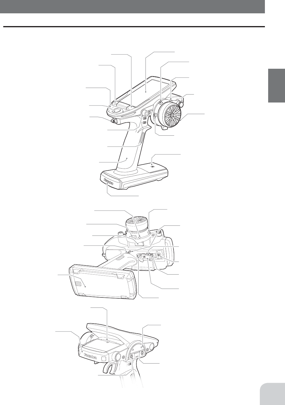
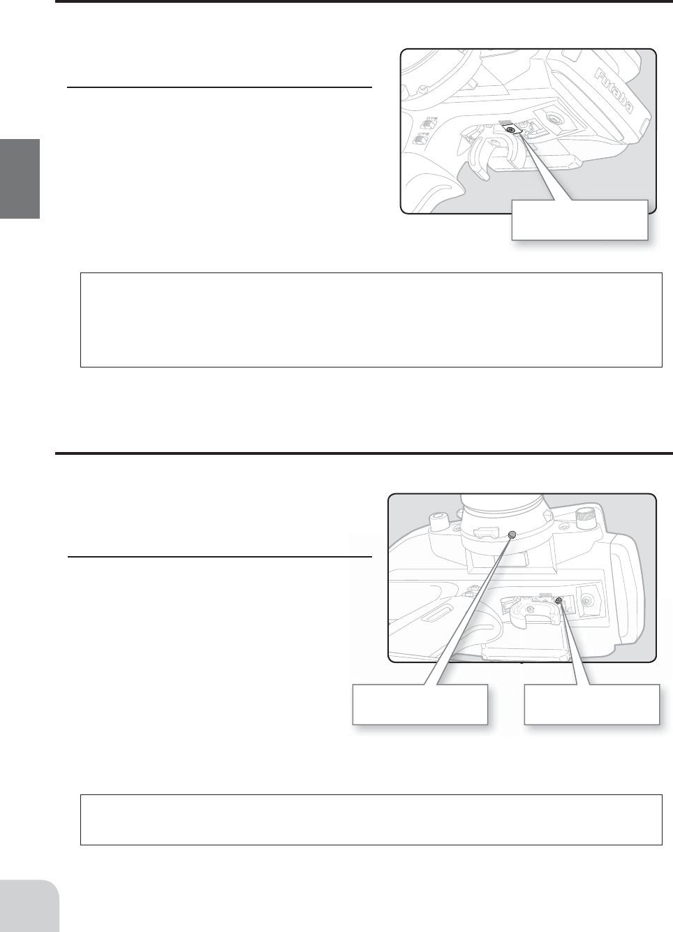
The switches, dial, and trimmers in the ¿ gure are shown in the initial setting position.
Please be careful not too strongly pressed the push switch.
Grip Handle
A vibration motor is built into the grip handle
and racing timer time-up, low battery alarm,
telemetry alarm, etc. Can be generated by
vibration.
Digital Dial (DL1)
/Push switch 6 (PS6)
Power switch
Display switch Digital Trim 2 (DT2)
(default throttle trim)
Digital Trim1 (DT1)
(default steering trim)
Digital Trim4 (DT4)
Steering wheel
Push switch 2 (PS2)
Push switch 3 (PS3)
Push switch 4 (PS4)
LED
Touch screen LCD
NFC
Home buttons
Hook
Nomenclature
Transmitter T7PX
High point spring
Convenient in trigger switch position
checks.
Mechanical ATL
adjusting screw
Throttle trigger
Digital Trim3 (DT3)
Digital Trim5 (DT5)
(default dual rate)
Push switch 1 (PS1)
Push switch 5 (PS5)
Digital Trim6 (DT6)
(default brake rate)
Wheel tension
adjusting screw
Trigger tension
adjusting screw
Battery cover
Trigger slide adjusting screw
Earphone Jack
(3.5mm stereo jack plug)
Telemetry data can be listened to with commer-
cial earphones.
Non-telematry LED
(Lights when the telemetry function is off.)
Antenna
Cover
Communication port
Charging jack
16
Before Using
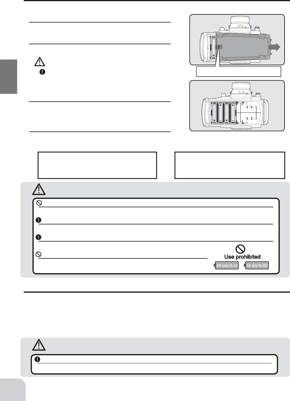
Battery cover
Battery Replacement Method
1 Remove the battery cover from the transmitter by
sliding it in the direction of the arrow in the figure.
2 Remove the used batteries.
Caution
If you remove the dry cell battery box from the
transmitter, replace it carefully with the wiring on the
same side as before. Reinstalling the battery box in
the opposite direction could cause the wires to be
disconnected.
3 Load the new AA size batteries. Pay very close
attention to the polarity markings and reinsert ac-
cordingly.
4 Slide the battery cover back onto the case.
Battery Replacement Method (4 AA Size Batteries)
Load the four batteries in accordance with the polarity markings on the battery holder.
Check:
Turn the power switch on the transmitter to the ON po-
sition. Check the battery voltage display on the LCD
screen. If the voltage is low, check the batteries for insuf-
¿cient contact in the case or incorrect battery polarity.
Disposal of the Dry Cell Batteries:
The method to dispose of used dry cell batteries de-
pends on the area in which you reside. Dispose of
the batteries in accordance with the regulations for
your area.
Caution
Never try to recharge a dry cell battery.
The transmitter may be damaged or the battery electrolyte may leak or the battery may break.
Insert the batteries in the correct polarity.
If the polarity is incorrect, the transmitter may be damaged.
When the transmitter is not in use, remove the batteries.
If the battery electrolyte leaks, wipe off the case and contacts.
Do not use commercial AA size NiCd and NiMH batteries.
Quick charging may cause the battery contacts to overheat and damage the battery
holder.
Low Battery Alarm
If the transmitter battery voltage drops below the usable range, an audible alarm will sound
and "Low battery" will be displayed (For details, see page 189). Since the usable range of
NiMH batteries and LiFe batteries is different, the power supply used must be set by system
setting (page 181). If the battery goes dead while running (cruising), since there is the dan-
ger of collision, immediately recover the vehicle (boat) and stop running (cruising).
Warning
When a low battery alarm is generated, cease operation immediately and retrieve the model.
If the battery goes dead while in operation, you will lose control of the model.
Slide battery cover while pressing here.
Battery cover
Slide battery cover while pressing here.
17
Before Using
Caution
When closing the battery cover, be careful that the battery cover does not pinch the battery lead
wires.
Shorting of the battery lead wires may lead to fire and abnormal heating and cause burns or fire disaster.
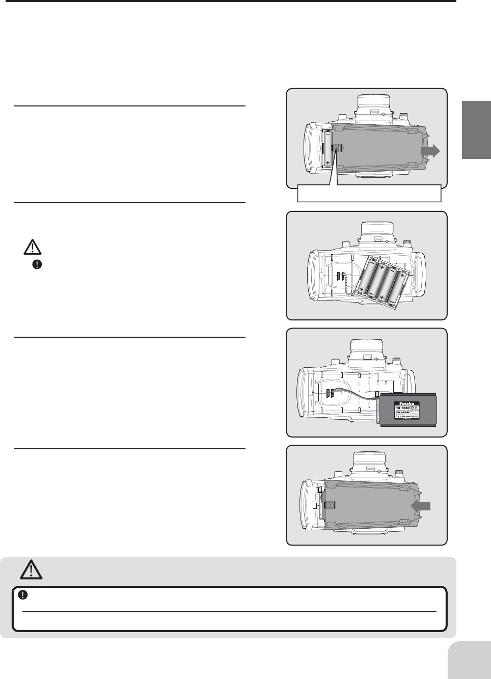
Battery Replacement Method
1 Refer to the previous description and remove
the transmitter battery cover.
When Using The Optional Battery
When using an optional rechargeable battery, replace the battery as described below.
-Always use the optional FT2F1700B , FT2F2100B or HT5F-1800B rechargeable battery.
-The type of power source used must be selected through the system setting (page 181).
-When the transmitter will not be used for a long time, remove the battery.
2 After removing the dry cell battery box from the
transmitter, disconnect the connector.
Caution
If you remove the dry cell battery box from the trans-
mitter, replace it carefully with the wiring on the same
side as before. Reinstalling the battery box in the op-
posite direction could cause the wires to be discon-
nected.
3 Insert the connector of the new battery and load
the new battery into the transmitter.
4 Finish by installing the battery cover.
AC outlet
Charger
Transmitter
charging LED
To transmitter
charging jack
To receiver
NiCd battery
18
Before Using
Warning
Charging A LiFe Battery
(Example: When using the
FT2F1700B/2100B
with the special charger)
1 Remove the battery cover.
2 Disconnect the battery from the T7PX.
3 Balance charging cannot be done through the
transmitter. You must remove the LiFe battery
to do this charge.
Charge the optional FT2F1700B/2100B (LiFe)
battery with the special charger in accordance
with the instruction manual supplied.
When the LiFe battery will not be used for a long
time, to prevent it from deteriorating we recom-
mend that it be kept in about the half capacity
state instead of fully charged. Also be careful
that the battery does not enter the overdischarged
state due to self-discharge. Periodically (about
every 3 months) charge the battery. In addition,
always remove the battery from the model and
store it in a dry, cool place (15Ca25C).
Over current protection
The transmitter charging circuit is equipped with an over cur-
rent protection circuit (1.0A). If the battery is charged with a
quick charger for other than digital proportional R/C sets, it
may not be fully charged.
The charging time when charging the HT5F1800B battery
with the optional special charger is approximately 15 hours.
However, when the battery has not been used for some time,
repeat charging 2 or 3 times to activate the battery.
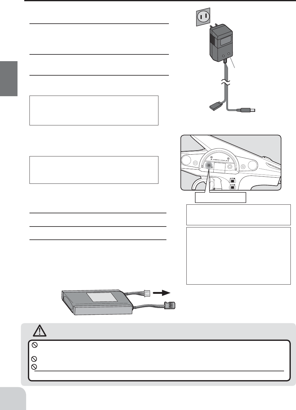
Charging A NiMH Battery
(Example: When using the HT5F1800B with the special charger)
1 Plug the transmitter cord of the special charger
into the charging jack on the rear of the trans-
mitter.
2 Plug the charger into an AC outlet.
3 Check that the charging LED lights.
When Charging For The Optional Battery
Balance charging connector for LiFe battery charger.
LiFe battery is removed from transmitter.
Make sure not to peel off the battery fi lm, or make any scratch by a cutter knife or the sharp edges of
metal components.
Make sure not to soak or get the battery wet with water or seawater.
Make sure not to use a deformed or swollen battery.
There is a risk of explosion or fi re, which is very dangerous.
Charging jack
Power & Display Switch
19
Before Using
Warning
Caution
Never plug it into an outlet having other than the indicated voltage.
Plugging the charger into the wrong outlet could result in an explosion or fi re.
Do not insert and remove the charger when your hands are wet.
It may cause an electric shock.
Always use the special charger or a quick charger for digital proportional R/C sets to charge a digital
proportional R/C set battery.
Overcharging a NiMH battery can result in burns, fi re, injuries, or loss of sight due to overheating, breakage, or electrolyte
leakage.
Do not plug the charger to the charging jack, if the battery is not connected to the transmitter.
The transmitter may be damaged.
When the charger is not in use, disconnect it from the AC outlet.
Do this to prevent accidents and to avoid overheating.
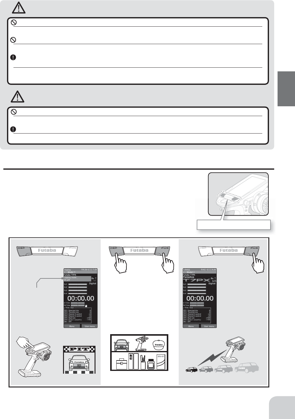
Power & Display Switch
The power switch and display switch are push switches.
When the power switch (PWR) is held down, operation starts by
transmitting radio waves. When the display switch (DSP) is held
down, the transmitter side data can be checked and set. When
the power is turned off, if the power switch or display switch is
held down, the power is turned off. If both switches are pressed
simultaneously, the power is turned off quickly.
OFFDSP PWR
When the power is turned off,
if the power switch or display
switch is held down, the power
is turned off. If both switches
are pressed simultaneously, the
power is turned off quickly.
Radio waves are not
being
transmitted.
"Display mode RF off"
is displayed Radio waves are
being transmitted.
When you do not run, turn OFFIt cannot operate. It can operate.
The current system is displayed.
(T-FHSS SR /T-FHSS /S-FHSS /FASST)
When turned on by DSP switch, "Dis-
play" is displayed
T-FHSS /S-FHSS /FASST - Response type
(Digital servo /Analog servo)
T-FHSS SR - SR mode on/off
(SR mode setting channel is a red SR mark.)
*The figure above is partly processed for explanation, so it is different from the actual screen display.
Trim/dial lock display mark
20
Before Using
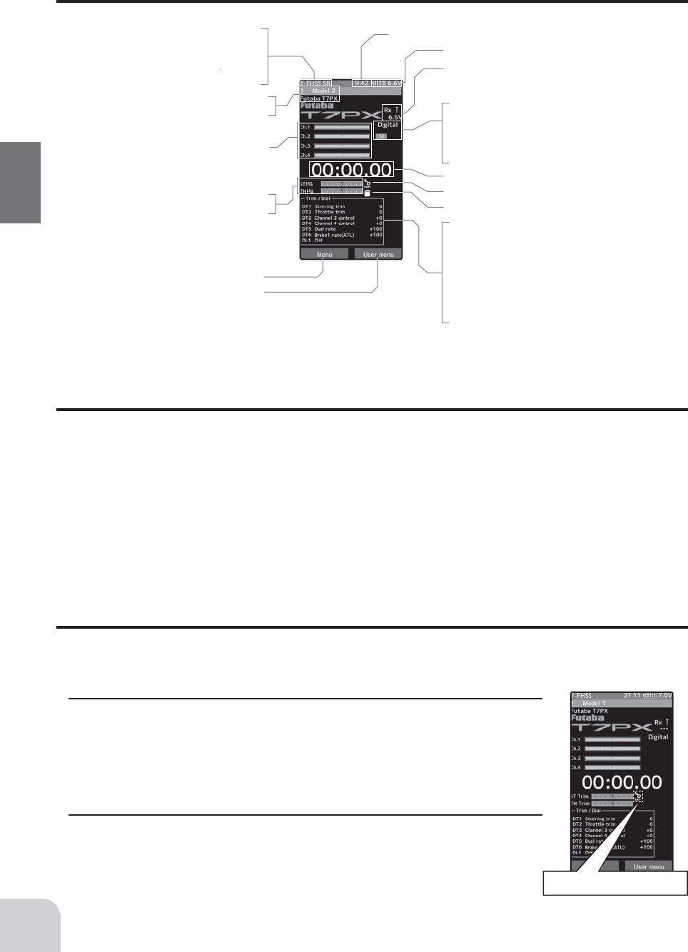
Display When Power Switch Is Turned On
DT1
DT2
DT3
DT4
DT5
DT6
DL1
Total timer or clock display (H:M)
Battery voltage display
Upper: Steering trim display
Lower: Throttle trim display
Menu button
User menu button
Racing timer
Trim/dial lock display mark
Micro SD card mark
Function names and rate as-
signed to dials are displayed.
Model #, Model name (15 characters)
User name (15 characters)
Telemetry function
Receiver -> Transmitter
The reception strength is shown.
Servo operation of each channel can be
checked.
(S-FHSS system Ch.1 to Ch.7)
Power Off Forgotten Alarm & Auto Power Off
At T7PX initialization, if steering wheel, throttle trigger, push switch, edit button, or other
operation is not performed within 10 minutes, an audible alarm will sound and the message
"Warning: Auto power off" will appear
(For details, see page 189.)
.
If steering wheel, throttle trigger, push switch, edit button or other operation is performed, the
alarm is reset. Also turn off the power when the transmitter is not in use. If the alarm is not
reset, the auto power off function will automatically turn off the power after 5 minutes. If you
do not want to use this alarm and the auto power off function, they can be disabled by system
setting (
page 181
).
Trim/Dial Lock
T7PX setup and operation by digital trim DT1, DT2, DT3, DT4, DT5 and DT6 and dials
DL1 can be prohibited.
Setting
1 When the Home button is pressed for about 1 second at the initial
screen, a confirmation beep is generated and the trim/dial lock display
mark appears on the screen.
Clearing
1 Edit button lock and trim/dial lock can be cleared in the initial screen
state by the same method as the setting described above. (The trim/dial
lock display disappears from the screen.)
DT5
DT6
Steering And Throttle Trim Operation
With the center trim feature, trim adjustments have no effect on the maximum servo travel.
This prevents the linkages from binding when adjustments are made.
• Each step is indicated by a tone.
• When the trim exceeds the maximum trim adjustment range, the beep will change and the servo will not move any
farther.
• When the steering wheel is neutral, adjust the steering trim so that the car goes straight without curving left and
right.
• Adjust the throttle trim so that the car stops when the throttle trigger is in neutral so
that the brake will not be applied when the throttle trigger is released during operation.
• Steering D/R :The steering left and right servo travels are adjusted simultaneously.
• ATL: Decreases the set value when the braking effect is strong and increases the set
value when the braking effect is weak.
1
2
3
4
5
67
8
• 1/3-DT1 (Steering trim display)
• 2/4-DT2 (Throttle trim display)
• 5-DT3 (Channel. 3 display)
• 6-DT4 (Channel. 4 display)
• 7-DT5 (Steering D/R display)
• 8-DT5 (ATL display)
21
Before Using
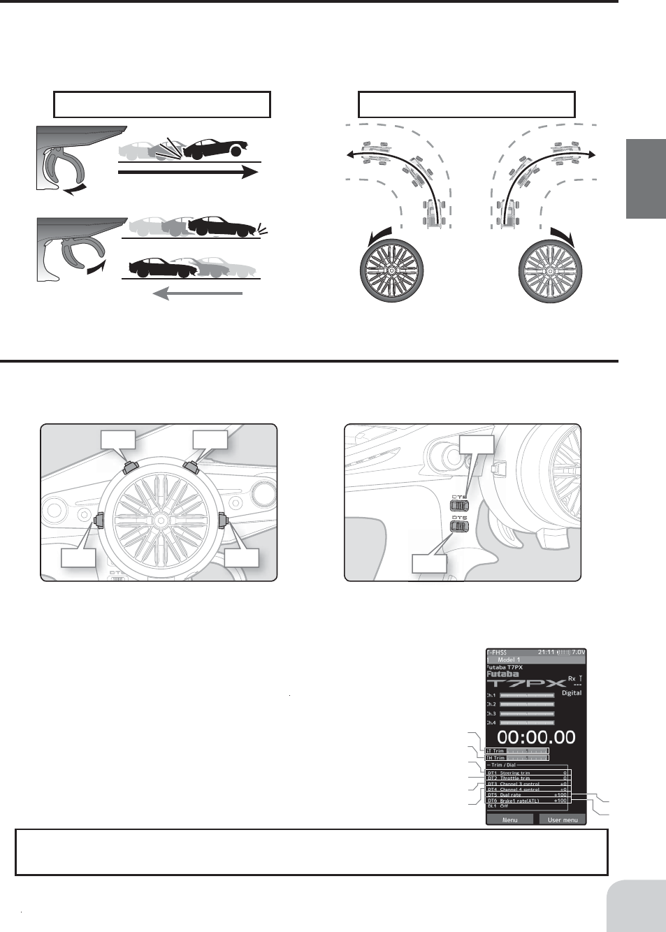
Throttle trigger function Steering wheel function
Left
Pull
Push
Left turn
Forward
brake or back
Right turn
Right
Steering Wheel And Throttle Trigger Operation
(CH1: Steering wheel, CH2: Throttle trigger)
Steering Wheel Function: Turns the model right or left.
Throttle Trigger Function: Controls the speed of the model as well as the direction of travel
- forward or reverse.
Digital Trim Operation
(Initial settings: DT1: Steering trim, DT2: Throttle trim, DT3: Channel 3, DT4: Channel 4, DT5: Steering D/R, DT6: ATL-Brake rate)
Operating by the trim: Push the trim lever to the left or right (up or down). The current po-
sition is displayed on the LCD screen.
DT1DT2
DT4 DT3
22
Before Using
Mechanical ATL
adjusting screw
Adjustment
1 Using a 1.5mm hex wrench, adjust the trigger
brake (reverse) stroke. (The screw moves the
throttle trigger stopper.)
• When the screw is turned clockwise, the stroke becomes
narrower. Adjust the stroke while watching the screw.
Note:
Mechanical ATL Adjustment
Make this adjustment when you want to decrease the stroke of the brake (back) side of the
throttle trigger for operation feel.
Wheel & Trigger Tension Adjustment
Make this adjustment when you want to change the wheel or trigger spring’s tension.
Adjustment
1 Using a 1.5mm hex wrench, adjust the wheel
spring tension by turning the screw inside the
adjusting hole.
• The spring is set to the weakest tension at the factory.
• When the adjusting screw is turned clockwise, the spring
tension increases.
Note:
Wheel tension
adjusting screw
Once you have changed the mechanical stroke on the brake side, be sure to adjust the
scale of the throttle channel accordingly by using the "Calibration Function" (page 184).
Due to this change, you also need to adjust in most cases the travel of the throttle servo
by using "Data Setting."
The adjustment range is up to 7 to 8 turns from the fully tightened (strongest) position. If
turned farther than this, the adjusting screw may fall out.
Trigger tension
adjusting screw
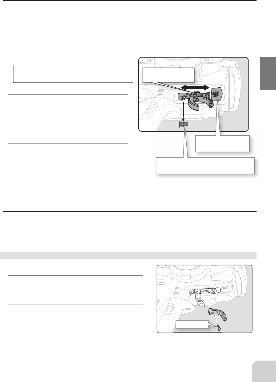
Please adjust it within the
range of mark.
High point spring can be removed
with radio pliers, etc.
Trigger slide
mounting screw
2.0x6 cap crew
23
Before Using
Adjustment
1 Using a 2.0mm hex wrench, loosen the trigger slide mounting screw by turning it slightly
counterclockwise.
Always loosen this screw.
2 Adjust the trigger slide position within the
marked range.
The high point spring can be removed by moving to
the farthest from the grip.
When the high point spring is removed, perform throt-
tle side correction by calibration function (page 184).
3 Retighten the mounting screw loosened at
step 1 and fasten the trigger slide.
Note:
If the trigger slide screw is turned too
much, the screw may fall out.
Trigger Slide Adjustment & Remove The High Point Spring
The throttle trigger position can be moved forward and backward.
Trigger brake lever replacement
The trigger brake lever is selected from a narrow nylon type and wide type. (Narrow type is
installed at the factory.)
When the brake lever is changed, perform throttle side correction by adjuster function (page 184).
1 Hold the trigger, remove the brake lever mounting
screw using the 1.5mm hex wrench, and remove
the brake lever.
2 Using the 1.5mm hex wrench install the wide type
brake lever with the brake lever mounting screw.
Obtain a 1.5mm hex wrench. Remove the battery
from the transmitter.
Brake lever replacement
24
Before Using
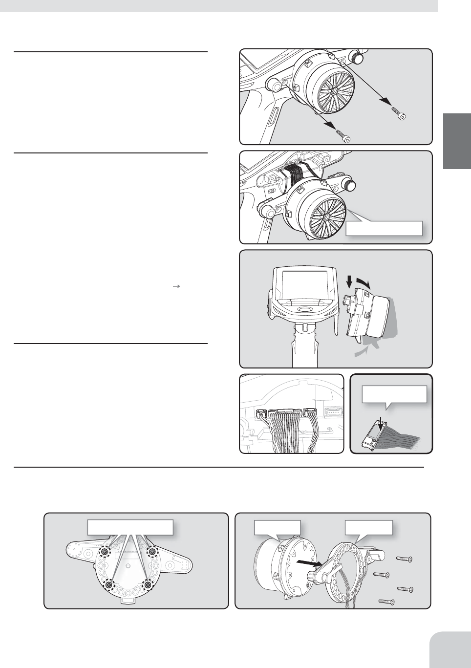
1 Hold the wheel and remove the screw.
(Using a 2.5 mm hex wrench.)
• Obtain 2.5mm hex wrench./ Remove the battery.
2 Pull off the wheel and wheel adapter.
3 Install the steering wheel and the 32
deg wheel adapter using the screw.
(Using a 2.5 mm hex wrench.)
Exchange procedure to wheel adaptor 32 deg
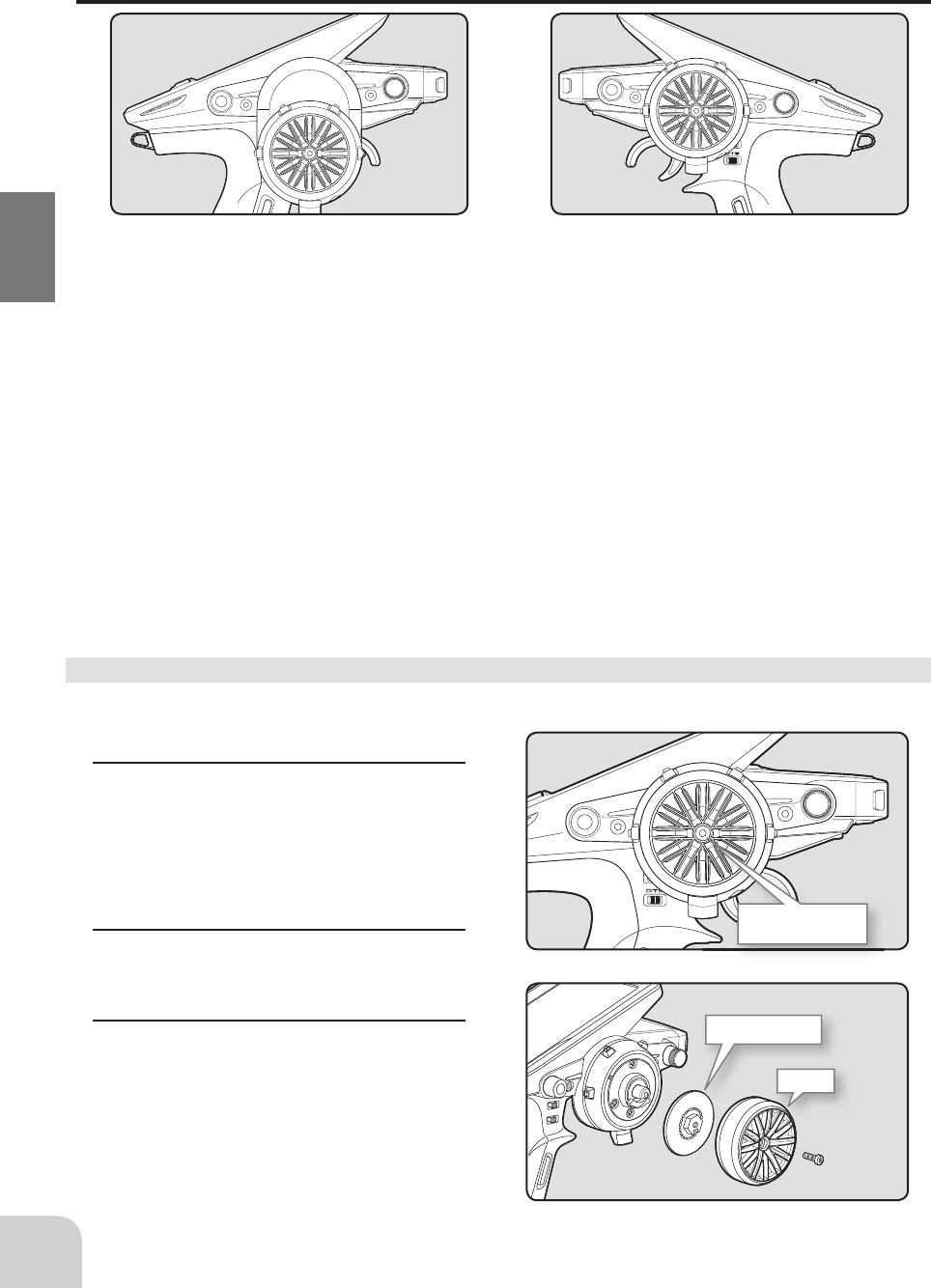
Changing Wheel Position And Modifying For Left-hand Use
Changing the wheel position
The wheel position can be offset by using the
accessory APA wheel position offset adapter.
(See page 25 for the modi¿ cation method.)
Angle can be adjusted
The angle can be fi nely adjusted by adjusting the steering wheel unit installation. (See the
modifi cation method on the next page for the adjustment details.)
The operating angle of the wheel can be adjusted
The operating angle of the wheel can be changed from 34 deg to 32 deg by installing the
32 deg wheel adjuster. (See "Exchange procedure to wheel adaptor 32 deg" below for the
replacement procedure.
If you install the 32 deg wheel adapter, be sure to adjust the scale of the steering channel
accordingly by using the "Calibration Function" (page 184).
Modifying for left-hand use
The wheel section left and right installa-
tion direction can be reversed.
(See page 25 for the modi¿ cation method.)
Steering wheel
mounting screw
Wheel
Wheel adapter
Steering wheel unit
1
2
3
Press to unlock
Unit mounting screws Wheel unit Switch unit
25
Before Using
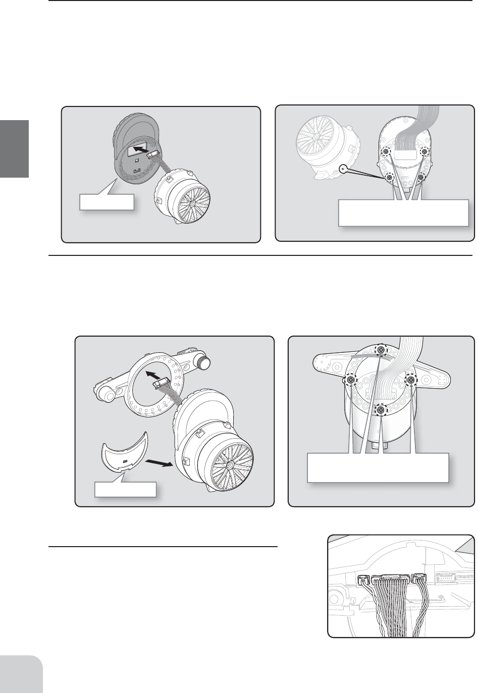
1 Remove the 2 steering wheel unit mount-
ing screws (3.0x12mm cap screw)
(Using a 2.5 mm hex wrench.)
Remove the 2 mounting screws completely from
the transmitter body.
• Obtain 2.5mm hex wrench./ Remove the battery.
• The length of the screws used at each part differs. When reassembling the steering wheel unit, always use the
specifi ed screws.
2 Gently remove the steering unit, without
pulling excessively on the wiring.
- Since there are claws on the top and bottom of the
steering unit, please do not pull straight out force-
fully.
- Please slowly remove in the order of 1 3 in the
right fi gure.
- Remove the steering unit slowly so that the inter-
nal wiring is not pulled unreasonably.
3 Remove the 3 connectors from the PC
board.
Press the upper side of the connector to release
the lock and remove it from the PC board.
(The 3 connectors each have the same lock type
although they are different in size.)
4 Using a Phillips screwdriver, remove the 4 screws (2.6x15mm tapping screw) mounting the
wheel unit and switch unit.
Installing the accessory APA steering wheel offset adapter
APA rear cover
Switch unit and APA mounting screws
(2.6x10mm tapping screws)
Adapter APA Wheel unit and APA mounting
screws (2.5x19mm tapping screws)
Marking
26
Before Using
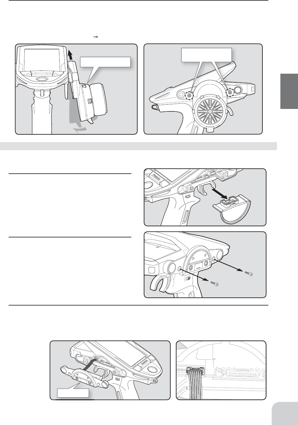
7 Install the assembled steering wheel unit to the
transmitter body.
• From left to right, the order is 2 pin connector (PS3), 15
pin connector (wheel unit), 4 pin connector (DL1 / PS6).
6 Using a Phillips screwdriver fasten the switch unit and APA. Use the 2.6x10mm tapping
screws in the accessories bag. Next, install the APA rear cover. Be careful that the length of
the screws is correct.
• The 2.6x10 tapping screws in the accessory bag
5 Pass the wiring from the steering wheel unit through the hole in the APA as shown in the
fi gure. Using a Phillips screwdriver fasten the wheel unit and APA at the desired angle using
the 2.6x19 tapping screws.
• Be careful that the screw length is correct. Be careful that the wiring does not get pinched.
• The 2.6x19 tapping screws in the accessory bag
• The angle can be adjusted, but check the marking point on the wheel unit and install the screws.
• Screws can be installed at 4 places, but installation at 4 places may be impossible due to the wheel unit mounting
angle.
Steering wheel unit
Steering wheel unit
mounting screws
Charge unit
1
2
27
Before Using
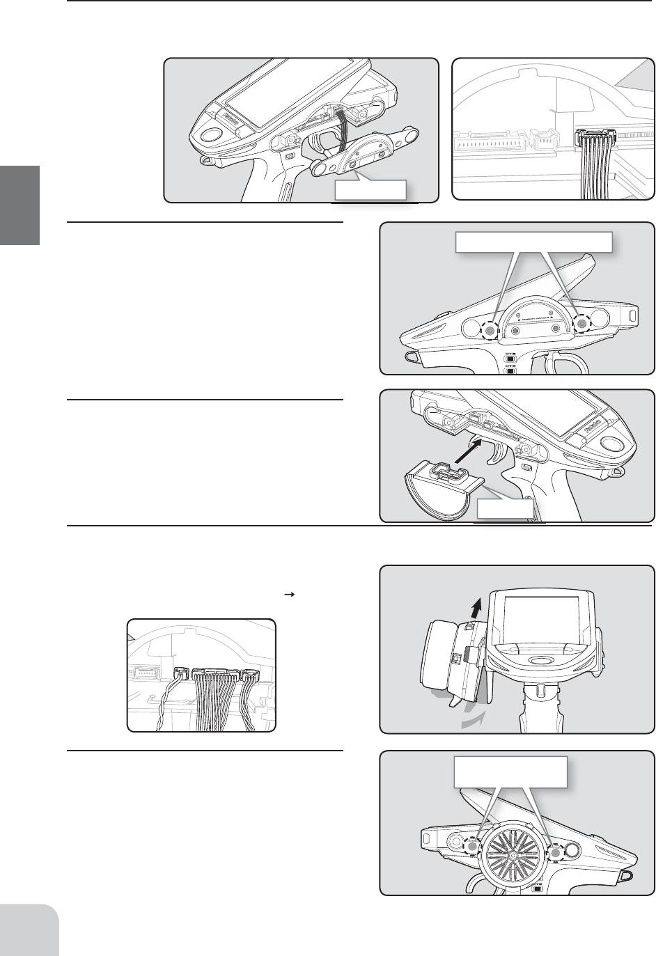
8 Install the assembled steering wheel unit and APA to the transmitter using the screw
(3.0x12mm cap screw) supplied.
(Using a 2.5 mm hex wrench.)
• Install slowly so that the wiring is not pinched.
• Installation is easy if inserted in 1 2 order.
1 Slowly pull out the PS5 switch cap and
mounting plate in the arrow direction.
• Be careful that the switch body does not get
caught and damaged.
2 Using a 2.5mm hex wrench, remove the
mounting screws (3.0x1.2mm cap) of the
opposite side charge unit.
• Remove the 2 mounting screws completely from
the transmitter body.
• Obtain 2.5mm hex wrench.
• Refer to 1-2 (p.25) of the APA for the wheel position change installation method.
Modifying for left-hand use
3 Being careful that the wiring is not too tight slowly remove the charge unit. Remove the con-
nector from the PC board.
• Press the upper side of the connector to release the lock and remove it from the PC board (See page 25).
Charge unit
Charge unit mounting screws
PS5 unit
1
2
Steering wheel unit
mounting screws
28
Before Using
4 Install the charge unit to the connector on the opposite side of the transmitter body.
• Install slowly so that the wiring is not pinched.
5 Using a 2.5 mm hex wrench, attach the
charging unit and the transmitter body
with fi xing screws.
6 Install the PS5 switch cap and mounting
plate removed at step 1 at the opposite
side of the transmitter body.
• Be careful that the switch body does not get
caught and damaged.
7 Insert the connector of the steering unit into the board on the opposite side of the transmit-
ter and attach it to the main unit.
• Install slowly so that the wiring does not get pinched.
• Installation is easy when inserted in 1 2 order. (Figure
at the right)
8 Install the assembled steering wheel
unit to the transmitter using the screw
(3.0x12mm cap screw) supplied.
(Using a 2.5 mm hex wrench.)
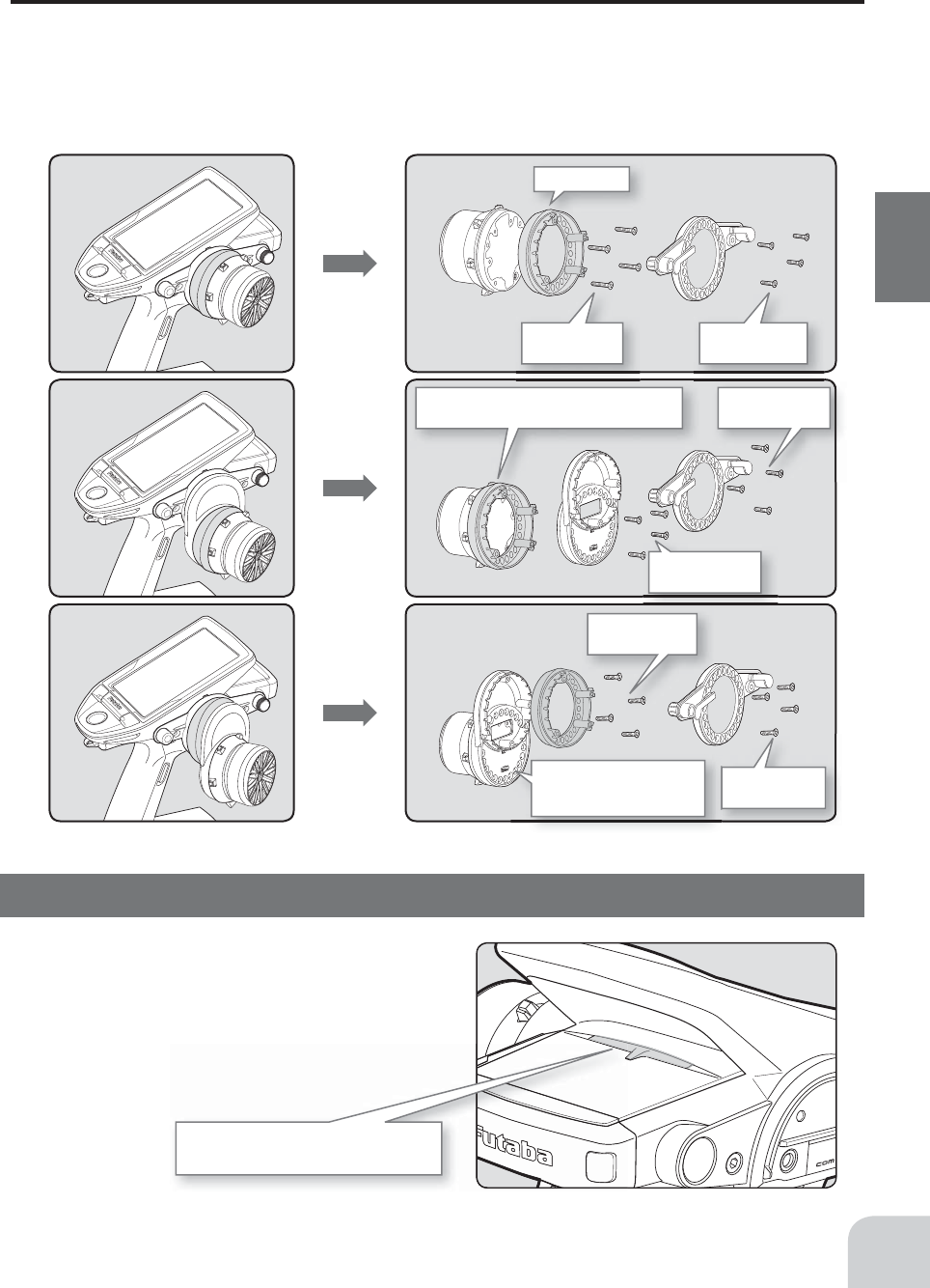
2.6x10mm
tapping screws
2.6x15mm
tapping screws
Angle spacer
2.6x10mm
tapping screws
2.6x10mm
tapping screws
Mount the angle spacer and wheel unit with
2.6x15mm tapping screws.
2.6x10mm
tapping screws
2.6x10mm
tapping screws
Mount the APA adapter and
wheel unit with 2.6x19mm
tapping screws.
29
Before Using
Using the optional angle spacer
The wheel mounting angle can be changed by using the optional angle spacer.
Three 2.6x10mm tapping screws are supplied with the angle spacer.
When using and not using the APA, refer to the following installation.
Obtain a Phillips screwdriver. Be careful of the length of the screws used.
Actually, since there is wiring, the wheel is assembled by passing the screws through each part.
Non-telemetry LED (telemetry OFF sign)
When the telemetry function is inhibited by
race regulations, a special LED lights when
the telemetry function is OFF to con¿ rm that
the telemetry function is not operating.
Non-telemetry LED
(Lit when telemetry function is OFF)
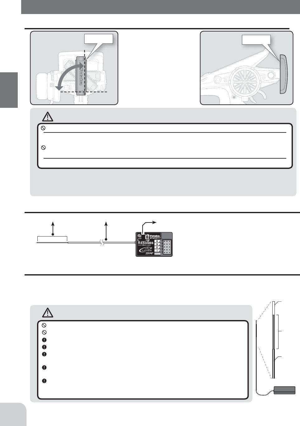
Caution
Cannot rotate more than
90˚.If rotated forcibly, the
antenna will be damaged.
WARNING
Antenna
tube
Antenna
Coaxial
cable
R334SBS
Do not cut or bundle the receiver antenna wire.
Do not bend the coaxial cable. It causes damage.
Install the antenna in the higher place as shown in the fi gure.
Put the antenna in the antenna tube to protect it.
Keep the antenna as far away from the motor, ESC and other noise sources as
you possibly can.
Wrap the receiver with something soft, such as foam rubber, to avoid vibration. If
there is a chance of getting wet, put the receiver in a waterproof bag or balloon.
It is a receiver of diversity type of external antenna and case internal antenna.
Do not place wiring or other objects on the plate. The receiving range may be af-
fected.
Antenna Coaxial cable 0USH switch/LED
Connectors
4 :CH4 servo(CH4)
3 :CH3 servo(CH3)
2 :Throttle servo(CH2)
1 :Steering servo(CH1)
S.BUS2 :
Power /S.BUS2 connector
The receiver power supply can be connected
to the S-BUS2 connector or each of CH1-4.
Antenna
Antenna
30
Before Using
Antenna Moving Range
Handling the antenna and card slot and receiver
About The Transmitter Antenna
Receiver Installation
Install the R334SBS receiver on the car as follows:
The operating range may become shorter, depending on where the receiver and the antenna
are mounted.
Receiver Terminology
Please do not grasp the transmitter's antenna during drive.
Doing so may degrade the quality of the RF transmission to the model.
The antenna position can be changed in the range as shown in fi gure. However, please do not ap-
ply unnecessary force or shock.
The internal cable may be damaged; thus transmitting distance decreases and it may cause malfunction.
There might be a small glitch when the antenna of the transmitter is brought close to ser-
vos, ESCs or other peripheral devices.
This is not an issue but please keep this symptom in mind, especially when setting-up.
If the antenna is set to the 45˚
and 90˚ vertical position, the
range of the radio waves may be
greater than in the horizontal po-
sition. (Different depending on the
conditions)
Caution
(Commercial product)
SD standard and SDHC standard microSD cards
*The data in the memory card cannot be guaranteed regard-
less of the contents and cause of trouble or damage. Always
back-up the valuable data in the memory card.
(Some models may not be operated by card.)
Caution
Always use R334SBS under the following conditions:
Battery :Power requirement Rated voltage 3.8~7.4V (dry cell battery cannot be used)
Matched to the ratings of the receiver and connected servo.
• Transmitter’s receiver system > T-FHSS SR-SR mode channel (ON): SR mode of Futaba SR compatible servo.
• Transmitter’s receiver system > T-FHSS SR-SR mode channel (OFF):
Normal mode of Futaba SR compatible servo.
&Futaba digital servo.
• Transmitter’s receiver system > T-FHSS/S-FHSS/FASST
Transmitter’s response type: Digital servo :Futaba digital servo
Transmitter’s response type: Analog servo :Futaba all servo (Normal mode of Futaba SR compatible servo.)
Under other conditions, the set will not operate, or the specifi ed performance will not be displayed even if it operates. In
addition, it may cause trouble with servos and other equipment. Futaba will not be responsible for damage, etc. caused by
combination with the products of other companies.
Note: However, digital servos (including BLS Series brushless servo) can only be used in the "Digital servo type".
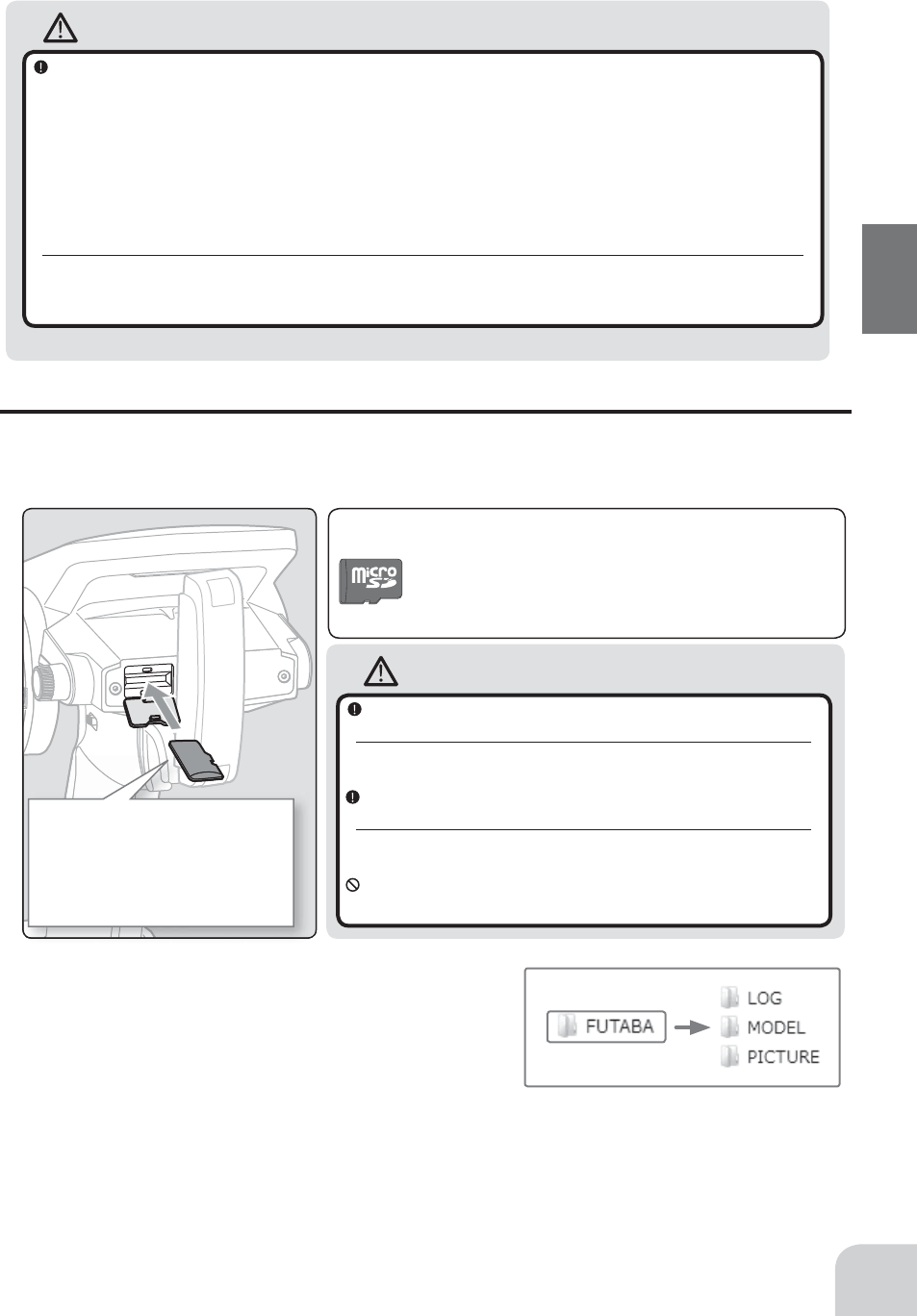
Insert the card with the metal termi-
nals side at the bottom.
Remove the card by pushing it in and
then pulling it out.
Install and remove the card by push-
ing it in until you hear a click.
31
Before Using
Handling an microSD card (commercial product)
T7PX model data and telemetry log data can be saved by using a commercial microSD
card. When T7PX software updates are released, the microSD card can also be used to
make the update.
Always insert and remove the microSD card in the state in
which the transmitter power is off.
If the microSD card is removed while being accessed (read or write), the
card itself and the data may be destroyed.
Do not install and remove the microSD card with the mi-
croSD card slot facing your face.
If you remove your fi ngers quickly, the microSD card may fl y out and
strike your face and is dangerous.
Since the microSD card is a precision device, do not subject
it to unreasonable force or shock.
-When a microSD card is installed in the T7PX trans-
mitter, a folder called "Futaba" is created. Folders called
"LOG" and "MODEL" are created in this folder. The
"MODEL" folder stores the model data and the "LOG"
folder stores the telemetry log data. When "Save screen"
is set at the push switch by switch setting, an image of
the screen to be displayed on the T7PX is saved by that switch. The saved image is stored in
a folder call "PICTURE". A "PICTURE" folder is not created until "Save screen" is set.
-The telemetry log data recorded on the microSD card can be converted to CS9 format by
the telemeter log converter released on our home page. When copying or moving a log ¿ le,
always select both .FLI and .FLD ¿ le.
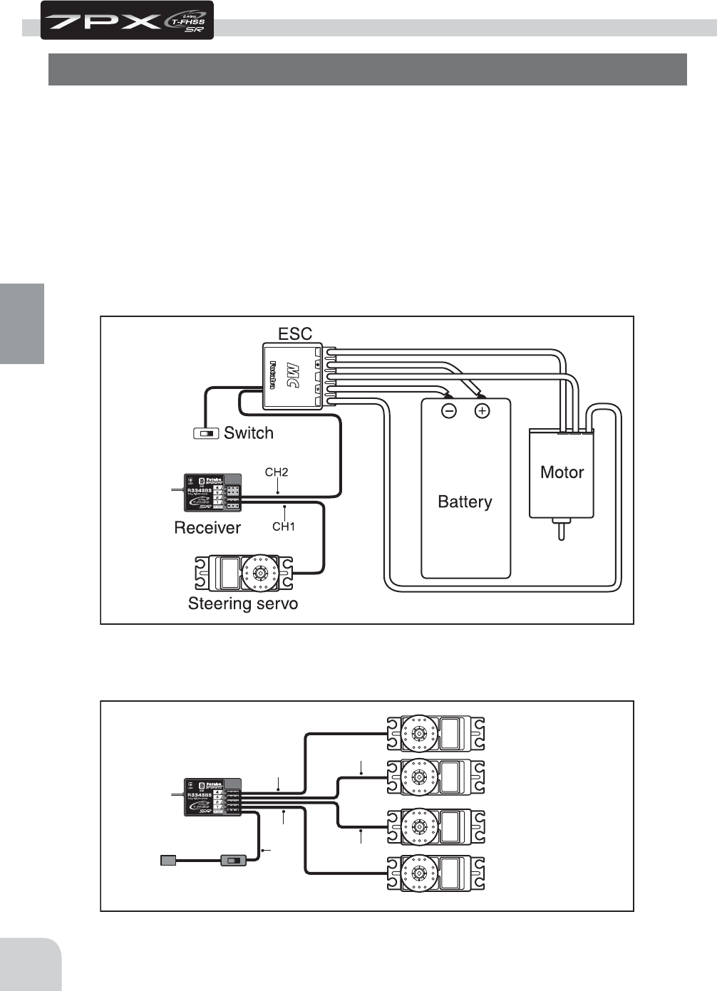
B/C
CH3
CH2
CH1
CH4
Receiver
Switch
To Battery
CH4 servo
CH3 servo
Throttle servo
Steering servo
#%$
Installation When An Electronic Speed Control Is Used
Installation For Gas Powered Models
32
Installation
Connect the receiver and servos as shown below. Connect and install the receiver and ser-
vos in accordance with "Installation Safety Precautions" on the next page.
The ¿gure shown below is an example. The method of connecting the motor controller to
the motor and battery depends on the motor controller used. Purchase the motor controller
and servos separately. The receiver also depends on the set.
When using the DSC cord with a gasoline engine car, connect the optional double extension
cord to B/C of the receiver and the DSC cord and receiver switch to the opposite side con-
nector.
Installation
Receiver And Servo Connections
Installation Safety Precautions
Warning
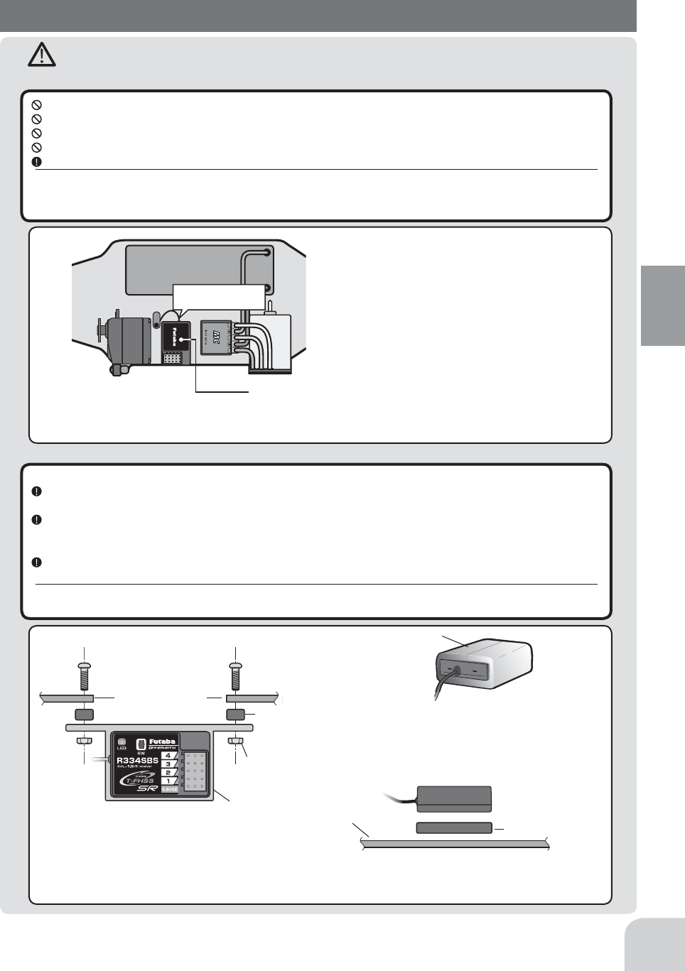
Receiver (receiver antenna)
Receiver Vibration-proofing / Waterproofing
Do not cut or bundle the receiver antenna wire.
Do not bundle the receiver antenna wire together with the motor controller lead wire.
Keep the receiver antenna wire at least 1cm away from motor, battery, and other wiring carrying heavy current.
Do not use a metal receiver antenna holder on a plate made of metal, carbon, or other conductive material.
Install the receiver antenna holder as closely as possible to the receiver.
If the antenna wire is cut, bundled, or routed near a noise source, the receiving sensitivity will drop, the running (cruising)
range will decrease, and you may lose control of the model.
Noise is transmitted through metal, carbon, and other conductive material, so keep the receiver antenna wire away from such parts.
(Car)
Vibration-proof the receiver by wrapping it in foam rubber or other vibration-absorbing material and mount it with
thick double-sided tape.
When using the receiver holder supplied with the model kit, mount the holder to the chassis through a rubber
grommet.
(Boat)
Vibration-proof the receiver by wrapping it in foam rubber or other vibration-absorbing material. Also waterproof
the receiver by cruising it in a plastic bag.
If the receiver is exposed to strong vibration and shock, it will operate erroneously due to the invasion of water drops and
you may lose control of the model.
Screw
Mechanical plate
Nut (as required)
Receiver holder
Damper
When using the receiver holder sup-
plied with the kit, install the receiver
through a rubber grommet.
Foam rubber, etc.
Wrap the receiver in foam rubber or other
vibration-absorbing material. Do not use
hard material. Hard material does not
have a vibration-proo¿ng effect.
Mechanical plate Thick double-
sided tape
When mounting the receiver with double-sided tape,
do not use a stiff tape. Stiff tape does not have a vibra-
tion-proo¿ng effect.
#%$
Install the receiver as far away as possible from the
battery, motor controller, motor, silicon cord and
other noise sources. .eep it away from the antenna
wire, in particular.
Since the antenna of built-in antenna receivers is installed
under this, do not place wiring or other objects on it.
Battery
Antenna
33
Installation
Warning
Connector Connections
Servo Installation
Be sure the receiver, servo, battery and connectors are fully and firmly connected.
If vibration from the model causes a connector to work loose while the model is in operation, you may lose control .
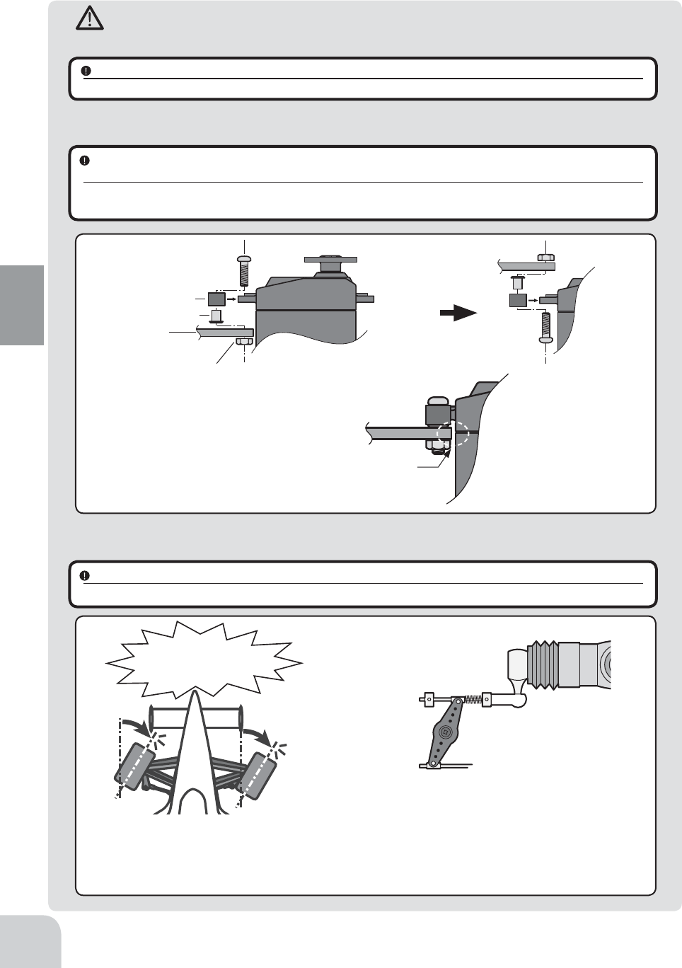
When you install the servos, always use the rubber grommets provided in servo hardware bags. Mount the
servos so they do not directly come in contact with the mount.
If the servo case comes in direct contact with the mount, vibration will be directly transmitted to the servo.
If this condition continues for a long time, the servo may be damaged and control will be lost.
Servo Throw
Operate each servo over its full stroke and be sure the linkage does not bind or is loose.
The continuous application of unreasonable force to a servo may cause damage and excessive battery drain.
Screw
Mechanical plate
Nut (as required)
Eyelet
Damper
(or)
When installing the servo, always install the accessory
rubber grommet and grommet Àush against the servo.
A vibration-damping effect is not obtained even
if the rubber grommet and grommet are not in-
stalled correctly.
Adjust the throttle servo so that unreasonable force is
not applied when the engine carburetor is fully open,
fully closed, and the brakes are applied fully.
If the brakes overheat while running, their ability to
function properly decreases. Before running, adjust the
suitable maximum servo travel so that unreasonable
force is not applied even when the servo travel is in-
creased while running.
Adjust the steering servo so that unreason-
able force is not applied to the servo by the
chassis at maximum servo travel.
Decide the EPA value at the
contact point.
Caution!
A whining noise indicates that the
steering servo is improperly set.
34
Installation
Warning
Electronic Speed Cont
Motor Noise Suppression
Install the heat sinks where they will not come in contact with aluminum, carbon fiber or other parts that conduct
electricity.
If the FET Amp (Electronic speed control) heat sinks touch other materials that conduct electricity a short circuit could oc-
cur. This could result in loss of control and damage to the system.
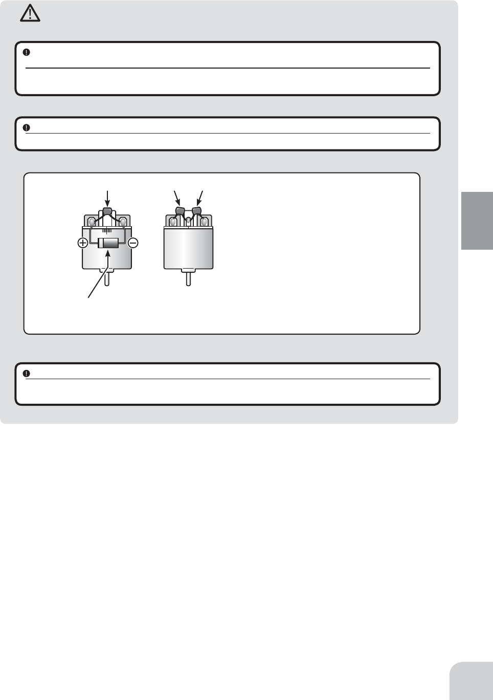
Always install capacitors to suppress noise when electric motors are used.
If capacitors are not properly installed you could experience erratic operation and reduced range as well as loss of control.
Other Noise Suppression Methods
Be sure there are no metal parts in your model which under vibration can come in contact with other metal parts.
Metal to metal contacts under vibration will emit a high frequency noise that will affect the receiver's performance. You
could experience erratic operation and reduced range as well as loss of control.
Motors with no suppressor capacitors, or inade-
quate suppression, may cause the receiver to mal-
function. Always solder the capacitors supplied to
your motor.
The Schottky diode improves the ef¿ciency of the
speed control / motor combination and provides
extra protection to the brake FETs. The white ring
must always face the positive side.
Schottky diode
"-" side
"+" side
123
35
Installation
For "T-FHSS SR" system
"T-FHSS SR" is displayed
36
Initial Set-Up
Before setting up each function of the transmitter, check and set the following items.
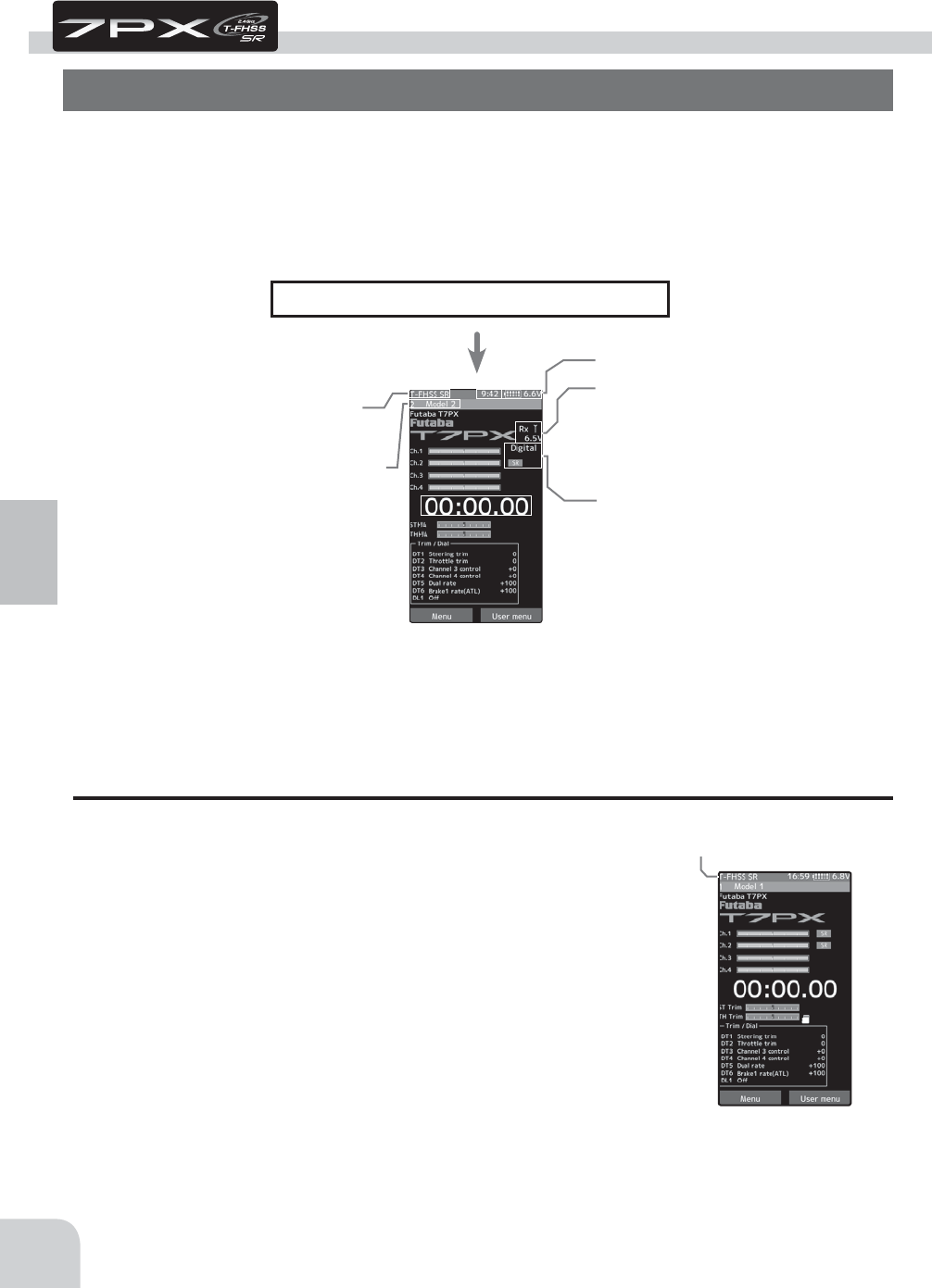
RF Output & Rx Type Check
Check if the receiver system is set to the type of receiver used.
*When the "PWR" side power switch is set to ON and radio waves
are output normally, "T-FHSS" SR, "T-FHSS", "S-FHSS", or "FASST"
is displayed. If not displayed, there is probably an abnormality or
trouble so contact a Futaba Service Center.
When a screen is displayed at the "DSP" side, "Display" is displayed.
*Since the R334SBS receiver supplied with the T7PX set uses the T-
FHSS SR (Super response) or telemetry function T-FHSS system,
T7PX receiver setup must be set to T-FHSS SR or T-FHSS.
The R2104GF and other S-FHSS and FASST system receivers, as
well as the R304SB T-FHSS system receiver can be used with the
T7PX transmitter. However, only R614FS/FS/FF-E and R604FS/FS-E
"C2" type receivers can be used with the FASST system.
The R603FS/FF "C1" type cannot be used.
Receiver system check
Receiver system check
Seervo response mode, SR mode check
Voltage check
Initial Set-Up
Preparations (Transmitter)
(Display when power switch turned on)
When the power switch is turned on, the currently selected model number is displayed.
Check if this number is the model number you want to set-up. To change the model number,
use the Model Select function. (page 170)
(HOME screen)
Turn on the transmitter power.
The model number is displayed
The figure is processed for ex-
planation of the screen. In fact,
response (digital / normal) and
SR mode are not displayed at the
same time.
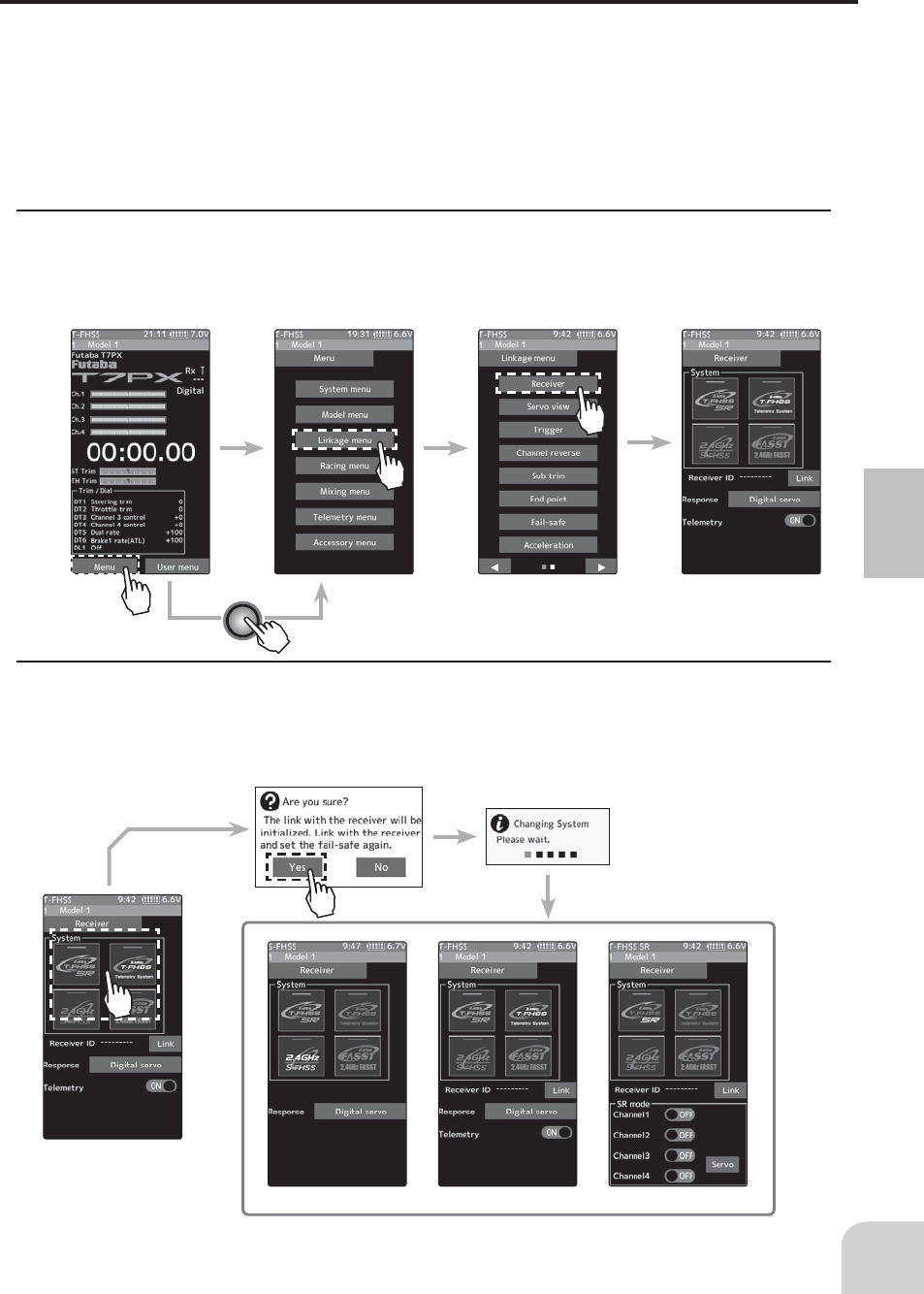
HOME Menu Linkage menu Receiver
* Even with the same receiver,
if you change the system, be
sure to rink with the receiver
and power cycle the receiver.
(Pages 38 to 39)
S-FHSS/FASST T-FHSS T-FHSS SR
37
Initial Set-Up
Receiver system Change & How To Link
First set up the receiver. Setting changes are immediately reÀected. Next, the transmitter
and receiver are linked and the receiver memorizes the transmitter ID number so that sig-
nals from other transmitters will not be received.
In addition, with the T-FHSS telemetry system, the transmitter simultaneously memorizes
the receiver ID numbers so that data from other receivers will not be received.
The method of setting up the receiver system and the method of linking the transmitter and
receiver are described. Refer to the ¿gure at the right for the edit buttons used.
1 Set the transmitter "PWR" side power switch to ON. From the Home screen, press the
Home button or tapped [Menu] on the touch panel. Next, select [Receiver] at the Linkage
menu and access the setup screen shown below by tapping the screen.
2 In "Receiver", select and tap the system to be set from T-FHSS SR, T-FHSS, S-FHSS,
FASST. The confirmation screen will be displayed. To execute, tap [Yes] to hear an electronic
sound and finish setting. To cancel, select [No] and touch it. If you change the system, be
sure to link it with the receiver and turn the power on again.
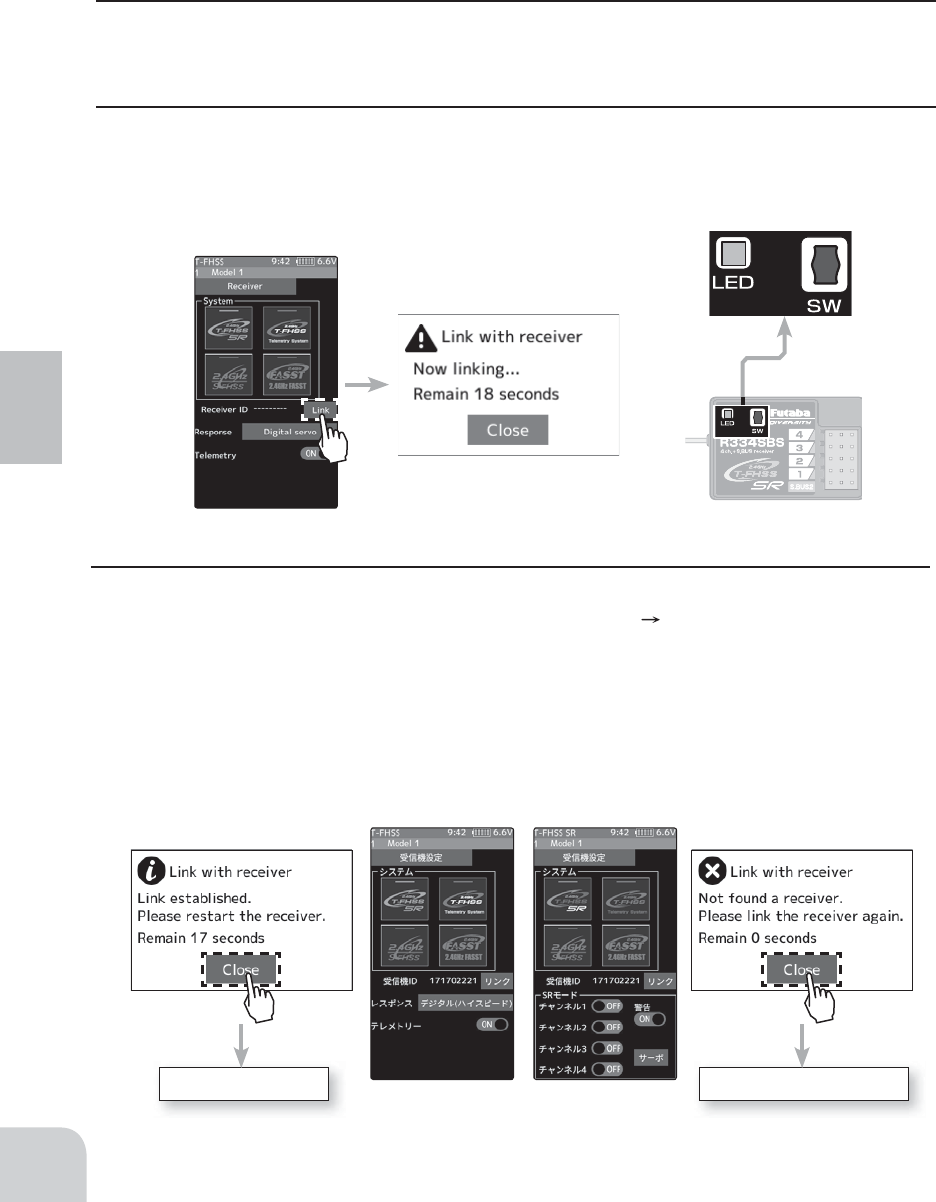
Receiver
R334SBS
Link failed
Link established
T-FHSS T-FHSS SR
The link is completed. Repeat the linking operation
38
Initial Set-Up
* After set up this far is complete, when using a FASST system (R614FS/FF/FF-E) or S-
FHSS system (R2104GF, R204GF-E, etc.) receiver, go to "Receiver other than T-FHSS" on
page 39. When using a telemetry function T-FHSS SR receiver (R334SBS) and T-FHSS re-
ceiver (R304SB, etc.) , go to step.
3 Bring the transmitter and receiver within 50cm of each other (antennas do not touch) and
turn on the receiver power.
4 Touch [Link] on the transmitter T7PX screen, you will hear a chime sound and T7PX will
enter the link mode for 20 seconds. During the 20 second link mode, push the receiver side
push switch for about 2 seconds or more.
5 During the 20 seconds link mode, press the receiver tactile switch for at least 2 seconds.
The LED blinks red and then changes to a greenish red green steady light. When the
T7PX makes a beeping sound and the message "Link with receiver" appears on the screen,
release the receiver tactile switch. This ends reading of mutual ID and displays the memo-
rized receiver ID number on the T7PX screen. Power cycle the receiver. If the "Receiver not
found" error screen is displayed, linking failed. Check the set contents and repeat the linking
operation.
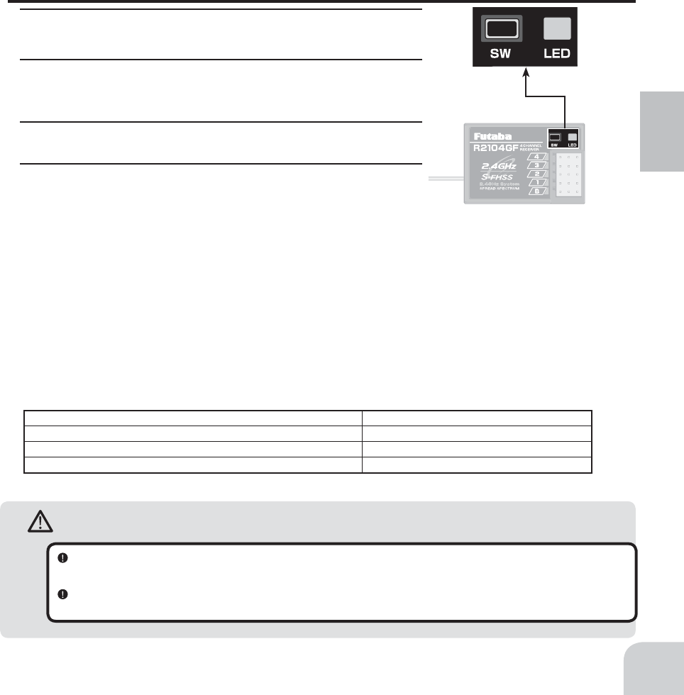
Warning
After the linking is done, please cycle receiver power and check if the receiver to be linked is really under the
control of your transmitter.
Do not perform the linking procedure with motor’s main wire connected or the engine operating as it may result in
serious injury.
No signal reception Red : On
Receiving signals Green: On
Receiving signals, but ID is unmatched. Green: Blink *1 (T-FHSS ,Red : On)
Unrecoverable failure (EEPROM,etc.) LED: Red and Green turn on alternately
*1: LED could be change to red during intermittently during data processing.
39
Initial Set-Up
* The T7PX and T-FHSS SR receiver (R334SBS)/ T-FHSS receiver (R304SB, etc.) memorize
the IDs linked last at each model memory. Since only one receiver ID is memorized at each
model memory, multiple T-FHSS SR/ T-FHSS receivers cannot be used with the sa me mod-
el memory. When a receiver at the same model memory is changed, re-linking is necessary
even if the receiver is already linked with the transmitter.
When using multiple T-FHSS SR/ T-FHSS receivers, link each receiver with each T7PX
model memory.
However, one receiver can be linked with multiple model memories. The telemetry function
communication status can be checked at the T7PX home screen.
Receivers Other Than T-FHSS
1 Bring the transmitter and the receiver close to each other,
within 20 inches (half meter).
2 Turn on the power switch (PWR). On the display (DSP) side,
you can not link.
3 Turn on the receiver.
4 Push the tactile switch of the receiver.
When the link is complete, the LED in the receiver changes
to solid green. Actually check the operation of the servo.
Precaution:
If there are many Futaba 2.4GHz systems turned on in close proximity to your receiver might not link to your trans-
mitter. In this case, even if the receiver’s LED stays solid green, unfortunately the receiver might have established a
link to one of other transmitters. This is very dangerous if you do not notice this situation. In order to avoid the prob-
lem, we strongly recommend you to double-check whether your receiver is really under control by your transmitter
by giving the stick input and then checking the servo response.
*Please refer to the table below for LED status vs receiver's condition.
LED status vs receiver’s condition:
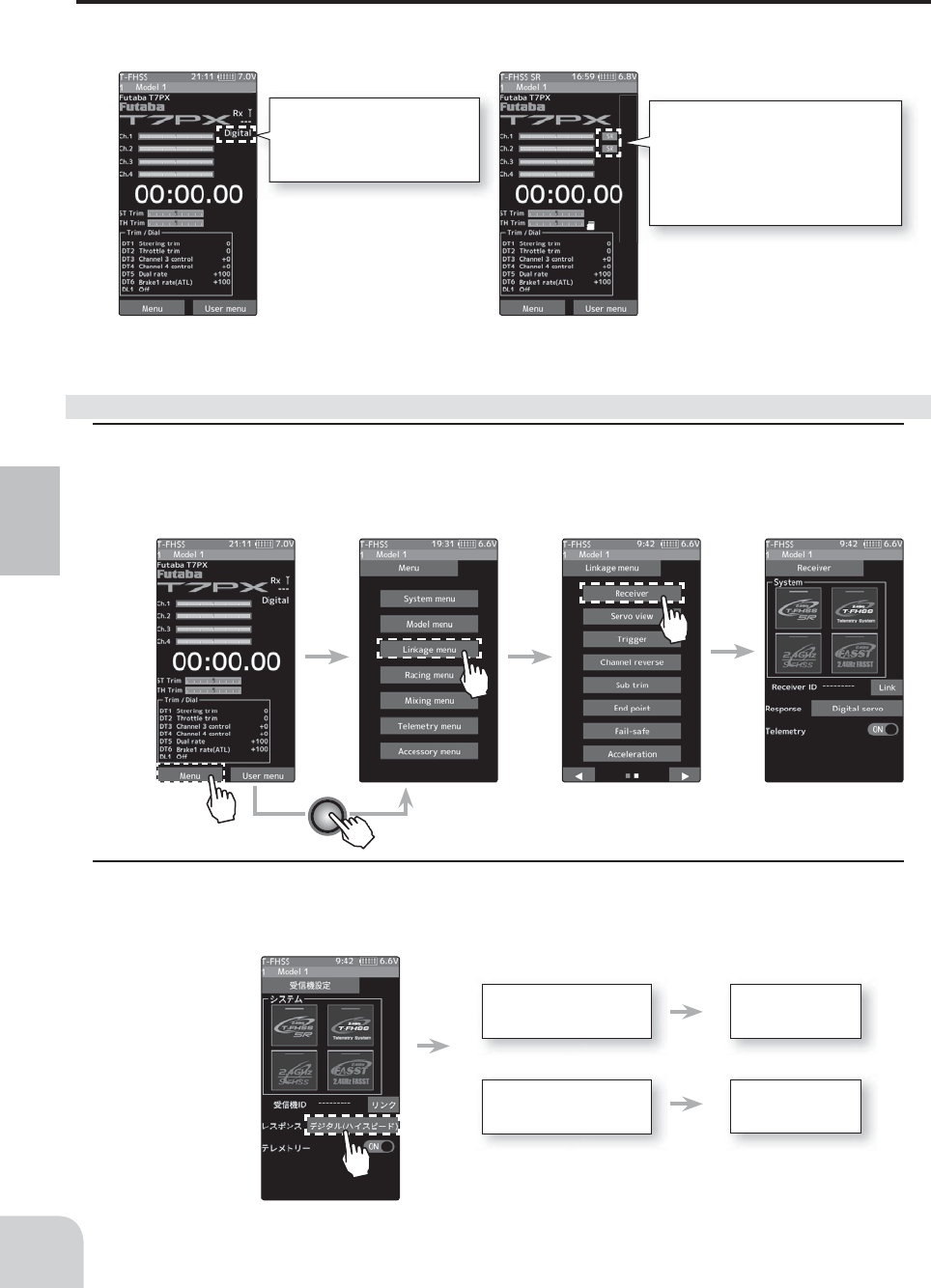
Response mode is displayed.
"Digital servo"
"Analog servo"
Display ON / OFF of SR mode.
In the case of the channel indicated
as [SR], SR mode is ON. If it is not
displayed, SR mode is OFF.
For SR mode, ON / OFF can be set
for each channel.
T-FHSS T-FHSS SR
How to set the response / SR mode
HOME Menu Linkage menu Receiver
Receiver
From a digital servo to
an analog servo
Changes to an
analog servo
Changes to a
digital servo
From an analog servo
to a digital servo
40
Initial Set-Up
If the setting is incorrect, change it by the following method.
Response Mode/ SR Check
Make sure that the response mode or SR mode setting matches the servo or other equipment
to be used.
1 From the Home screen, press the Home button or tapped [Menu] on the touch panel. Next,
select [Receiver] at the Linkage menu and access the setup screen shown below by tapping
the screen.
2 For the T-FHSS / S-FHSS / FASST system, touch [Digital Servo] or [Analog Servo] in the
receiver setting and make changes. The display changes when mode is changed.
When the power of the receiver is turned on, be sure to turn the power off and then on
again.
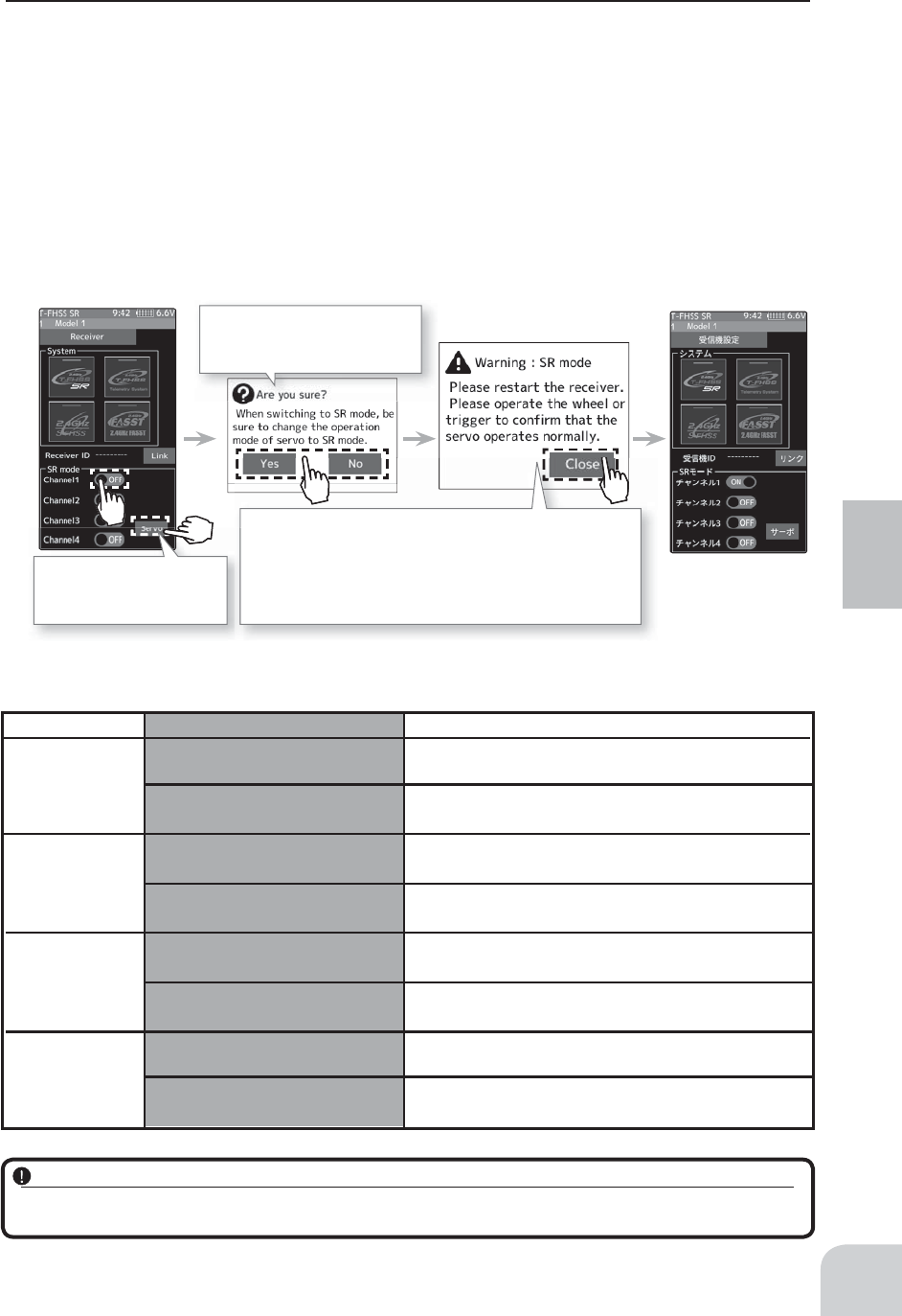
To change SR mode setting,
tapped [Yes], and if you want to
cancel, tapped [No].
The servo operation confi rmation message is displayed. With
this screen displayed, turn the power of the receiver off and
on again and check the operation of the servo by actually
operating it. If the servo does not operate properly, check the
SR mode setting (page 135) of the servo. Tap [Close] to close
the screen.
By tapping [Servo], you can
go directly to the S.BUS
servo menu (page 135).
Be sure to use the T7PX receiver setting and the servo to be used under predetermined conditions.
Under other conditions, the set will not operate, or the specifi ed performance will not be displayed even if it operates. In addition, it
may cause servo trouble. Futaba will not be responsible for damage, etc. caused by combination with the products of other companies.
T-FHSS SR
T-FHSS
S-FHSS
FASST
SR mode channel: ON
SR mode channel: OFF
-SR mode of Futaba SR compatible servo.
-
Normal mode of Futaba SR compatible servo.
-
Futaba digital servo.
-
Normal mode of Futaba SR compatible servo.
- Futaba digital servo.
-
Futaba all servo.
(Normal mode of Futaba SR compatible servo.)
-
Normal mode of Futaba SR compatible servo.
- Futaba digital servo.
-
Futaba all servo.
(Normal mode of Futaba SR compatible servo.)
-
Normal mode of Futaba SR compatible servo.
- Futaba digital servo.
-
Futaba all servo.
(Normal mode of Futaba SR compatible servo.)
Digital servo
Analog servo
Digital servo
Analog servo
Digital servo
Analog servo
System
Response / SR node Usable servos
41
Initial Set-Up
In the case of T-FHSS SR, "SR mode" which has greatly improved response compared to
the conventional T-FHSS can be used. Tap and change (ON)/ (OFF) of each channel of SR
mode. The display changes when you change it. Be sure to turn off the power of the receiv-
er before operation check.
In SR mode, ON/ OFF can be set for each channel. When using normal servo or ESC, set
the SR mode of the connected channel to (OFF).
Note: In SR mode ON, normal servo and ESC will not operate. Please set our S.BUS servo corre-
sponding to SR mode to SR mode on S.BUS servo menu on page 135 and use it. Also, in case of SR
mode OFF, the servo set to SR mode can not be used, so set the servo to normal mode by S. BUS ser-
vo menu. If using wrong combination, servo and other equipment will fail, so please be careful.
Servo conforming to the setting of response / SR mode