G4S Technology S822 S822 Access Control Proximity Reader User Manual S822 User Instructions
G4S Technology Limited S822 Access Control Proximity Reader S822 User Instructions
S822 User Instructions

Installation and User Instructions for S822 Readers
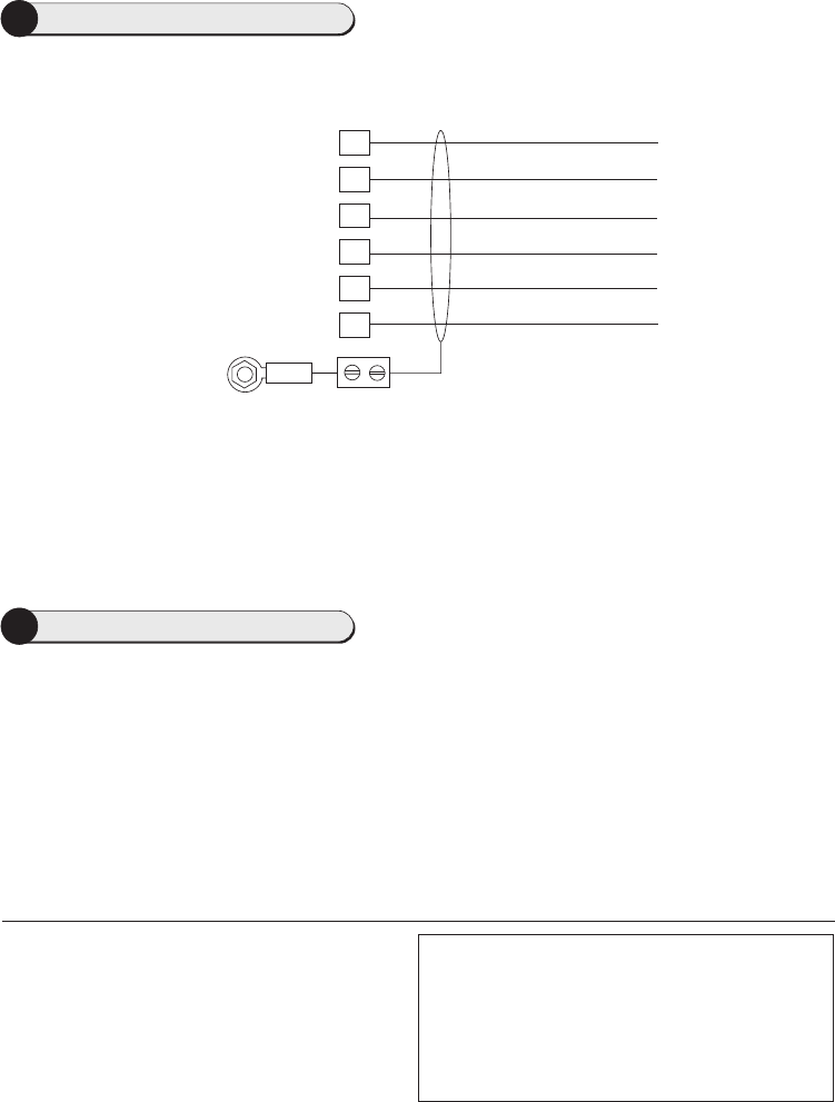
1Mount the Backplate
To mount the backplate:
1) Detach the main body of the reader from the
backplate by releasing the two securing screws
along the bottom edge of the reader.
2) Mount the backplate adjacent to the opening edge
of the door and at a convenient height. Feed the
cable to the reader through the backplate.
The backplate has suitable holes for connection to most standard electrical backboxes.
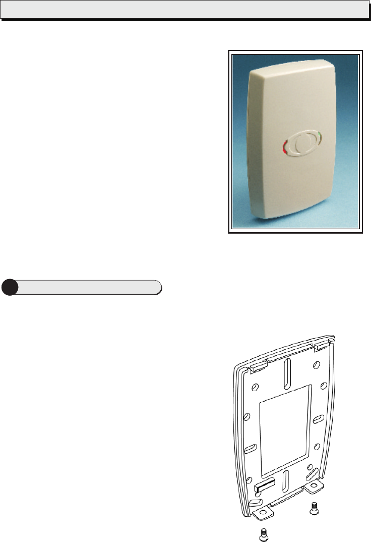
The S822 is a contactless smart-card reader, which uses
p . The
S822 is able to read HID i smart cards, and the
card serial number on Philips MIFARE smart cards.
For either type of card, the S822 supports the use of
unencoded cards (where only the unique card serial
number is read). In the case of HID i cards, an
encoded card number can be read. Encoding formats
supported include HID's own formats and the "smartMAX"
format.
CLASS
CLASS
TM
20mA current loop seudo-random communications
®
®®

9600-0305. Installation and User Instructions for S822 Readers,
Issue 1.0x10 18th November 2003. AMAG Technology, 2003.
of HID Corporation.
Philips and MIFARE are registered trademarks of Philips
Electronics, NV.
FCC Notice: This device complies with Part 15 of the FCC Rules.
Operation is subject to the following two conditions: (1) This
device may not cause harmful interference, and (2) this device
must accept any interference received, including interference that
may cause undesired operation.
Any unauthorized modification to this device may void the
authority of the user to operate it.
All trademarks acknowledged. HID is a registered trademark of
HID Corporation. i is a trademarkCLASS
©Specifications
Input voltage: 9-14V.
Input current: 100mA @ nominal 12Vdc supply.
Operating temperature: -13 to 158 F (-25 to 70 C).
Operating humidity: 15 to 90%, non-condensing.
Maximum read range: 2.5" (65mm).
Approvals: EN50133, R&TTE, IP656.
°°
3Using the Reader
Present the card face-on to the reader until you hear a "bleep". If the green indicator is lit, the card
has been accepted and the door is unlocked. If the red indicator is lit, either the card has not been
accepted, or you do not have access through the door. If the read and green indicators flash
alternatively, please wait.
cards can be presented in rapid succession - there is no need to wait for the green or red
LED to extinguish before presenting another card.
Note:
2Reader Connections
20mA Current Loop Reader Connections
0V
Connect shield at
controller end only
(connect to case)
Tx-
Tx+
Rx-
Rx+
12V
Controller connections
(20mA reader port)
Red
Black
White
Blue
Green
Orange
Note: the brown
wire is not used
Reader