GE MDS DS-EL806-24 2.4 GHz TransNet User Manual xxxxA TNET2 4 OEM Body
GE MDS LLC 2.4 GHz TransNet xxxxA TNET2 4 OEM Body
GE MDS >
Contents
- 1. Users Manual Part 1
- 2. Users Manual Part 2
- 3. Users Manual Part 3
- 4. Users Manual Part 4
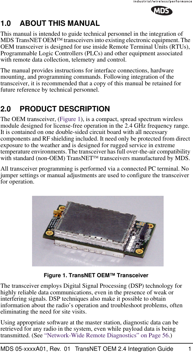
Users Manual Part 1
![ii TransNET OEM Integration Guide MDS 05-xxxxA01, Rev. 01 5.1 Mounting Dimensions .......................................................215.2 Antennas & Feedlines ......................................................21Feedlines...........................................................................22 6.0 OPTIMIZING PERFORMANCE...............................................236.1 Antenna Aiming ................................................................236.2 Antenna SWR Check .......................................................236.3 Data Buffer Setting ...........................................................236.4 Hoptime Setting ................................................................236.5 Operation at 115200 bps ..................................................246.6 Baud Rate Setting ............................................................246.7 Radio Interference Checks ...............................................246.8 RF Output Setting .............................................................247.0 OPERATING PRINCIPLES & SPECIAL CONFIGURATIONS ........................................................................257.1 How Remotes Acquire Synchronization ...........................257.2 Establishing a Tail-End Link ..............................................257.3 Store & Forward (SAF) Operation w/Extension Radios ....26Simple Extended SAF Network.........................................26Extended SAF Network.....................................................27Retransmission and ARQ operation..................................28Synchronization in SAF Networks.....................................28Configuration Parameters for S&F Services .....................297.4 Sleep Mode Operation (Remote units only) .....................31Sleep Mode Example........................................................32 8.0 DEALING WITH INTERFERENCE..........................................32 9.0 PROGRAMMING REFERENCE .............................................349.1 Programming Methods .....................................................34Terminal Interface Mode....................................................34PC-Based Configuration Software ....................................349.2 User Commands ..............................................................34Entering Commands .........................................................359.3 Detailed Command Descriptions ......................................40ADDR [1–65000]...............................................................40AMASK [0000 0000–FFFF FFFF].....................................41](https://usermanual.wiki/GE-MDS/DS-EL806-24.Users-Manual-Part-1/User-Guide-411407-Page-4.png)
![MDS 05-xxxxA01, Rev. 01 TransNET OEM Integration Guide iiiASENSE [HI/LO]............................................................... 41BAUD [xxxxx abc] ............................................................. 41BUFF [ON, OFF]............................................................... 41CODE [NONE, 1…255] .................................................... 42CTS [0–255]...................................................................... 42CTSHOLD [0–60000]........................................................ 43DEVICE [DCE, CTS KEY] ............................................... 43DLINK [xxxxx/ON/OFF]..................................................... 43DKEY................................................................................ 44DTYPE [NODE/ROOT] ..................................................... 44FEC [ON, OFF]................................................................. 44HOPTIME [7, 28] .............................................................. 44INIT................................................................................... 44HREV................................................................................ 45KEY................................................................................... 45LEDS [ON, OFF]............................................................... 45MODE [M, R, X]................................................................ 45OWM [xxxxx]..................................................................... 45OWN [xxxxx] ..................................................................... 45PORT [RS232, RS485]..................................................... 45PWR [20–30] .................................................................... 46REPEAT [0–10]................................................................. 47RETRY [0–10]................................................................... 47RSSI ................................................................................. 47RTU [ON, OFF, 0-80] ........................................................ 48RX [xxxx]........................................................................... 48RXTOT [NONE, 0–1440] .................................................. 48SAF [ON, OFF] ................................................................. 48SETUP.............................................................................. 48SER .................................................................................. 49SHOW PWR ..................................................................... 49SHOW SYNC.................................................................... 49SKIP [NONE, 1...8] ........................................................... 49SLEEP [ON, OFF]............................................................. 50SREV................................................................................ 50STAT ................................................................................. 50TEMP................................................................................ 50TX [xxxx]........................................................................... 50UNIT [10000–65000] ........................................................ 50](https://usermanual.wiki/GE-MDS/DS-EL806-24.Users-Manual-Part-1/User-Guide-411407-Page-5.png)
![iv TransNET OEM Integration Guide MDS 05-xxxxA01, Rev. 01 XADDR [0–31]...................................................................51XMAP [00000000-FFFFFFFF] ..........................................51XPRI [0–31].......................................................................51XRSSI [NONE, –40...–120]...............................................51ZONE CLEAR ...................................................................51ZONE DATA.......................................................................51 10.0 TROUBLESHOOTING...........................................................5210.1 Alarm Codes ...................................................................53Checking for Alarms—STAT command .............................53Major Alarms vs. Minor Alarms .........................................53Alarm Code Definitions .....................................................5310.2 LED Indicators ................................................................5410.3 Troubleshooting Chart ....................................................5410.4 Network-Wide Remote Diagnostics ................................55 11.0 FIRMWARE UPGRADES......................................................5711.1 Obtaining new firmware ..................................................57Saving a Web-site firmware file to your PC.......................5711.2 Installing firmware in your radio ......................................57 12.0 Security .................................................................................57 13.0 Product Specifications...........................................................5813.1 Detailed Pin Descriptions ...............................................59 14.0 dBm-Watts-Volts Conversion Chart.......................................66 To Our Customers We appreciate your patronage. You are our business. We promise to serve and anticipate your needs. We strive to give you solutions that are cost effective, innovative, reliable and of the highest quality possible. We promise to build a relationship that is forthright and ethical, one that builds confidence and trust. Copyright Notice This manual and all software described herein are Copyright 2004 by Microwave Data Systems Inc. All rights reserved. Microwave Data Systems Inc. reserves its right to correct any errors or omissions in this manual without obligation to any party.](https://usermanual.wiki/GE-MDS/DS-EL806-24.Users-Manual-Part-1/User-Guide-411407-Page-6.png)