GE MDS DS-EL806-24 2.4 GHz TransNet User Manual xxxxA TNET2 4 OEM Body
GE MDS LLC 2.4 GHz TransNet xxxxA TNET2 4 OEM Body
GE MDS >
Contents
- 1. Users Manual Part 1
- 2. Users Manual Part 2
- 3. Users Manual Part 3
- 4. Users Manual Part 4
Users Manual Part 2
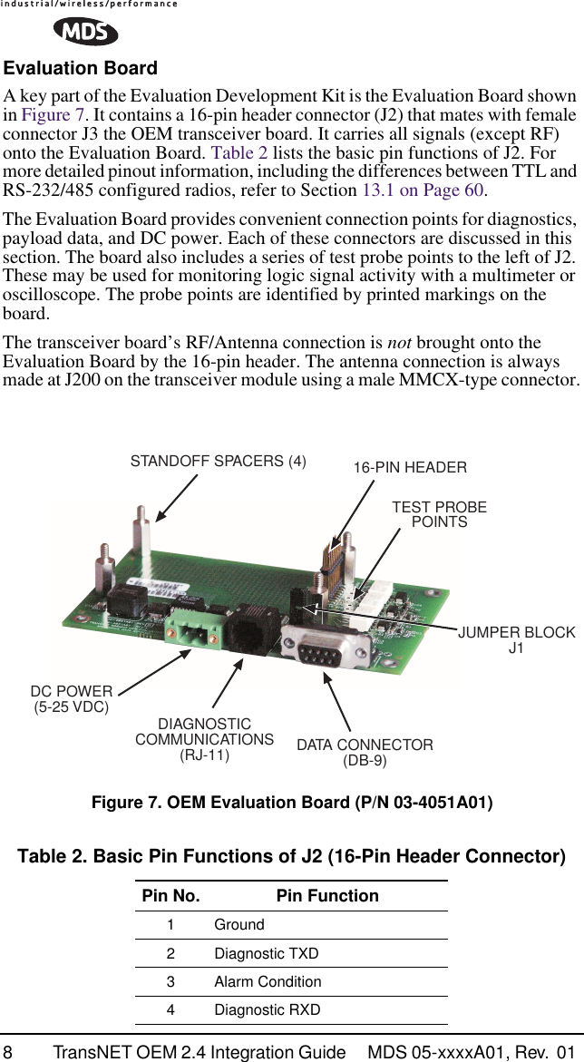
![MDS 05-xxxxA01, Rev. 01 TransNET OEM 2.4 Integration Guide 13Pin Descriptions—RS/EIA-232 ModeTable 3 lists the DATA connector pin functions for radios configured to operate in RS/EIA-232 mode.Pin Descriptions—RS/EIA-422/485 ModeTable 4 on the following page lists the DATA connector pin functions for radios configured to operate in RS/EIA-422/485 mode. See Figure 12 for wiring schemes.NOTE: Radios equipped with a payload RS-232/485 interface can select PORT RS485 for RS/EIA-485 mode. Table 3. J5 DATA Connector Pinouts—RS/EIA-232 PinNumber Input/Output Pin Description1 OUT Data Carrier Detect (DCD)—A low indicates hopping syn-chronization has been achieved.2 OUT Received Data (RXD)—Supplies received payload data to the connected device.3IN Transmitted Data (TXD)—Accepts payload data from the connected device.4IN Sleep Mode Input—A ground on this pin turns off most cir-cuits in a remote radio. This allows for greatly reduced pow-er consumption, yet preserves the radio’s ability to be brought quickly back on line. See “Sleep Mode Operation (Remote units only)” on Page 31 for details.5IN Ground—Connects to ground (negative supply potential).6 OUT Alarm condition—A low indicates normal operation. A high indicates an alarm. (See ASENSE [HI/LO] command for more information.)7IN Request to Send (RTS)—A high causes CTS to follow after the programmed CTS delay time has elapsed (DCE).8 OUT Clear to Send (CTS)—Goes high after the programmed CTS delay time has elapsed (DCE), or keys an attached ra-dio when RF data arrives (CTS KEY).9 -- Reserved—Do not connect.](https://usermanual.wiki/GE-MDS/DS-EL806-24.Users-Manual-Part-2/User-Guide-411408-Page-6.png)