GE MDS DS-EL806-24 2.4 GHz TransNet User Manual xxxxA TNET2 4 OEM Body
GE MDS LLC 2.4 GHz TransNet xxxxA TNET2 4 OEM Body
GE MDS >
Contents
- 1. Users Manual Part 1
- 2. Users Manual Part 2
- 3. Users Manual Part 3
- 4. Users Manual Part 4
Users Manual Part 2
8 TransNET OEM 2.4 Integration Guide MDS 05-xxxxA01, Rev. 01
Evaluation Board
A key part of the Evaluation Development Kit is the Evaluation Board shown
in Figure 7. It contains a 16-pin header connector (J2) that mates with female
connector J3 the OEM transceiver board. It carries all signals (except RF)
onto the Evaluation Board. Table 2 lists the basic pin functions of J2. For
more detailed pinout information, including the differences between TTL and
RS-232/485 configured radios, refer to Section 13.1 on Page 60.
The Evaluation Board provides convenient connection points for diagnostics,
payload data, and DC power. Each of these connectors are discussed in this
section. The board also includes a series of test probe points to the left of J2.
These may be used for monitoring logic signal activity with a multimeter or
oscilloscope. The probe points are identified by printed markings on the
board.
The transceiver board’s RF/Antenna connection is
not
brought onto the
Evaluation Board by the 16-pin header. The antenna connection is always
made at J200 on the transceiver module using a male MMCX-type connector.
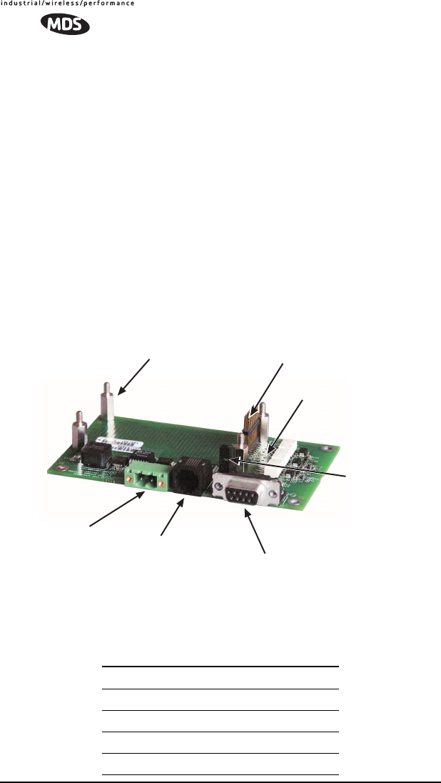
Figure 7. OEM Evaluation Board (P/N 03-4051A01)
Table 2. Basic Pin Functions of J2 (16-Pin Header Connector)
Pin No. Pin Function
1 Ground
2 Diagnostic TXD
3 Alarm Condition
4 Diagnostic RXD
TEST PROBE
POINTS
DIAGNOSTIC
COMMUNICATIONS
(RJ-11) DATA CONNECTOR
(DB-9)
DC POWER
(5-25 VDC)
STANDOFF SPACERS (4) 16-PIN HEADER
JUMPER BLOCK
J1
MDS 05-xxxxA01, Rev. 01 TransNET OEM 2.4 Integration Guide 9
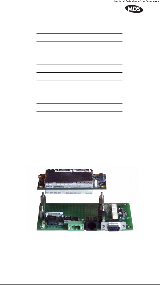
Connecting the Evaluation Board & Transceiver (Figure 8)
To connect the Evaluation Board to the radio, carefully align the pins of the
16-pin header with J3 on the transceiver module and press down firmly. The
radio PC board should seat solidly on the four standoff spacers. Use nuts to
secure the board to the standoffs.
Invisible place holder
Figure 8. Connecting the Evaluation Board and Transceiver Together
CAUTION:
Take care to avoid short-circuiting the underside of the Evaluation PC
board. The bottom of the board is
not
insulated, and contact with metallic
objects on the work surface could cause damage to the board or connect-
ed equipment.
5 DC Input
6 Sleep Mode Input
7 Data Carrier Detect (DCD)
8 Power Supply Shutdown Control
9 Reserved—Do not connect.
10 Transmitted Payload Data (TXD)
11 DC Input
12 Request to Send (RTS)
13 Reserved—Do not connect.
14 Received Payload Data (RXD)
15 Ground
16 Clear to Send (CTS)
Table 2. Basic Pin Functions of J2 (16-Pin Header Connector)
10 TransNET OEM 2.4 Integration Guide MDS 05-xxxxA01, Rev. 01
3.2 Cable Connections for Benchtop Testing
There are four basic requirements for operating the transceiver and evaluation
board in a benchtop test environment. They are:
• Adequate and stable primary power
• A proper antenna system or RF load (50 Ohms)
• The correct interface wiring between the transceiver and the connected
DTE device (RTU, PLC, etc.)
• A connected PC terminal to read/set transceiver parameters.
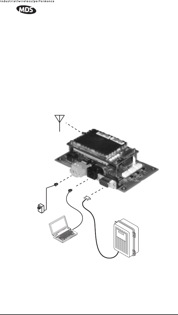
Figure 9 shows a typical setup for bench testing an OEM Transceiver. Two
such setups will be required if you intend to establish over-the-air
communications with another OEM transceiver.
Invisible place holder
Figure 9. Typical Test Setup
Antenna Connection (J200 on the transceiver module)
The Antenna connector is located at the upper left corner of the transceiver
module and is a female MMCX-type coaxial connector. Connect an antenna
or other suitable RF load to this connector. Only approved antenna/cable
assemblies may be used with the radio
OEM Transceiver
and Evaluation Board
ANTENNA
(OR 50-OHM RF LOAD)
PC TERMINAL
DATA TERMINAL
EQUIPMENT
Power Supply
13.6 VDC @
500 mA (min.)
MDS 05-xxxxA01, Rev. 01 TransNET OEM 2.4 Integration Guide 11
Do not apply DC power to the transceiver without first
attaching a proper RF load, or the transceiver may be
damaged.
Diagnostic Connection (J4)
J4 is an RJ-11-6 modular connector used to connect the evaluation
board/transceiver to a PC terminal for programming and interrogation. An
RJ-11 to DB-9 Adapter Cable (Part No. 03-3246A01) is required for this
connection. If desired, an cable may be constructed for this purpose as shown
in Figure 10. Only Pins 4, 5, and 6 of the RJ-11 connector should be used.
Pins 1, 2, and 3 are reserved for factory test purposes.)
The data parameters of the diagnostics port are as follows: 8 data bits, 1 stop
bit, and no parity. It automatically configures itself to function at 1200, 2400,
4800, 9600, 19200, 38400, 57600, and 115200 bps, as required.
Invisible place holder
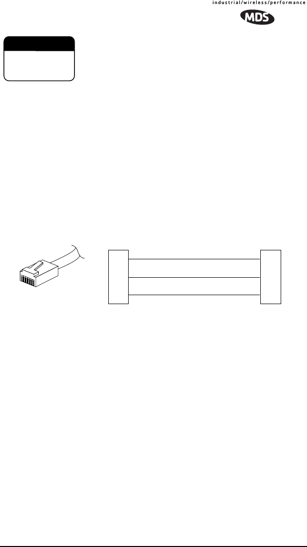
Figure 10. RJ-11 to DB-9 Diagnostic Cable—Wiring Details
(A pre-constructed cable is also available, Part No. 03-3246A01)
Diagnostic Communication Modes
Two methods may be used to communicate with the radio’s diagnostic port:
•
Terminal Interface
—The PC is used in its basic terminal emulation
mode, (i.e., HyperTerminal session) and commands are issued as simple
text strings.
•
Radio Configuration Software
—Proprietary software from MDS that
runs under the Windows operating system. It provides a graphical user
interface with “point and click” functionality. The program is included
on the
TransNET Support Package
CD shipped with every radio order.
Both of these control methods are described in more detail in the section titled
“PROGRAMMING REFERENCE” on Page 34. This section also includes a
chart listing all commands for the OEM transceiver.
CAUTION
POSSIBLE
EQUIPMENT
DAMAGE
RXD
TXD
GND
2
3
5
DB-9 FEMALE
(TO COMPUTER)
TXD
RXD
GND
4
5
6
RJ-11 PLUG
(TO TRANSCEIVER)
RJ-11 PIN LAYOUT
16
12 TransNET OEM 2.4 Integration Guide MDS 05-xxxxA01, Rev. 01
Data Connector (J5)
J5 on the Evaluation Board (Figure 11) is the data interface for the
transceiver. It is used to connect the transceiver to an external DTE terminal
that supports the EIA/RS-232 or EIA/RS-485 format, depending on how the
radio hardware was configured at the factory. The data connector supports
interface data rates of 1200, 2400, 4800, 9600, 19200, 38400, 57600, and
115200 bps (asynchronous only). The connector mates with a standard DB-9
plug available from many electronics parts suppliers.
Data Wiring Connections
The connections made to J5 will depend on the requirements of the DTE
device being used with the transceiver, and the operating functions that you
require. Only the required pins for the application should be used. Do not use
a straight through “computer” type cable that is wired pin-for-pin.
Typical RS/EIA-232 applications require the use of Pin 2 (receive
data—RXD) and Pin 3 (transmit data—TXD). Additionally, some systems
may require the use of Pin 7 (Request-to-send—RTS). If hardware flow
control is desired, Pin 7 (RTS) and Pin 8 (CTS) may also need connection.
Table 3 gives pin details for radios configured for RS/EIA-232 service.
Table 4 gives details for radios configured for RS/EIA-485 service.
NOTE: Radios equipped with a payload TTL interface are presented as RS-232 mode
from the Evaluation Board.
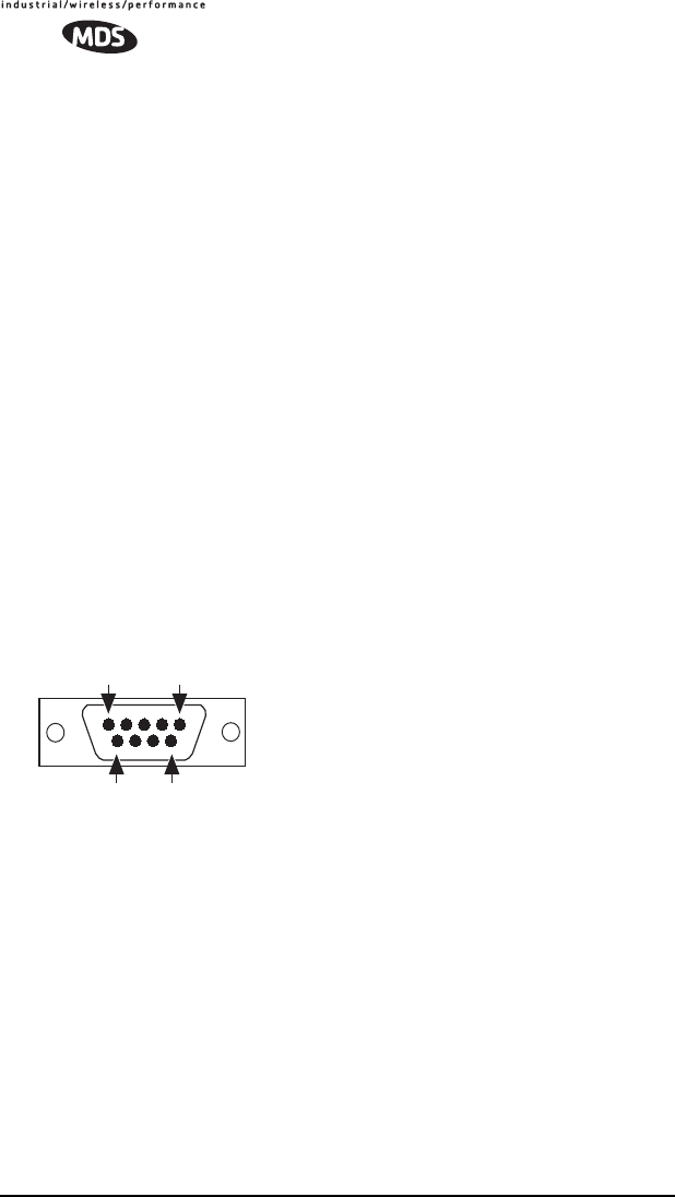
Figure 11. DATA Connector (DB-9F)
As viewed from outside the device
5
96
1

MDS 05-xxxxA01, Rev. 01 TransNET OEM 2.4 Integration Guide 13
Pin Descriptions—RS/EIA-232 Mode
Table 3 lists the DATA connector pin functions for radios configured to
operate in RS/EIA-232 mode.
Pin Descriptions—RS/EIA-422/485 Mode
Table 4 on the following page lists the DATA connector pin functions for
radios configured to operate in RS/EIA-422/485 mode. See Figure 12 for
wiring schemes.
NOTE: Radios equipped with a payload RS-232/485 interface can select PORT RS485
for RS/EIA-485 mode.
Table 3. J5 DATA Connector Pinouts—RS/EIA-232
Pin
Number Input/
Output Pin Description
1 OUT Data Carrier Detect (DCD)—A low indicates hopping syn-
chronization has been achieved.
2 OUT Received Data (RXD)—Supplies received payload data to
the connected device.
3IN Transmitted Data (TXD)—Accepts payload data from the
connected device.
4IN Sleep Mode Input—A ground on this pin turns off most cir-
cuits in a remote radio. This allows for greatly reduced pow-
er consumption, yet preserves the radio’s ability to be
brought quickly back on line. See “Sleep Mode Operation
(Remote units only)” on Page 31 for details.
5IN Ground—Connects to ground (negative supply potential).
6 OUT Alarm condition—A low indicates normal operation. A high
indicates an alarm. (See ASENSE [HI/LO] command for
more information.)
7IN Request to Send (RTS)—A high causes CTS to follow after
the programmed CTS delay time has elapsed (DCE).
8 OUT Clear to Send (CTS)—Goes high after the programmed
CTS delay time has elapsed (DCE), or keys an attached ra-
dio when RF data arrives (CTS KEY).
9 -- Reserved—Do not connect.
14 TransNET OEM 2.4 Integration Guide MDS 05-xxxxA01, Rev. 01
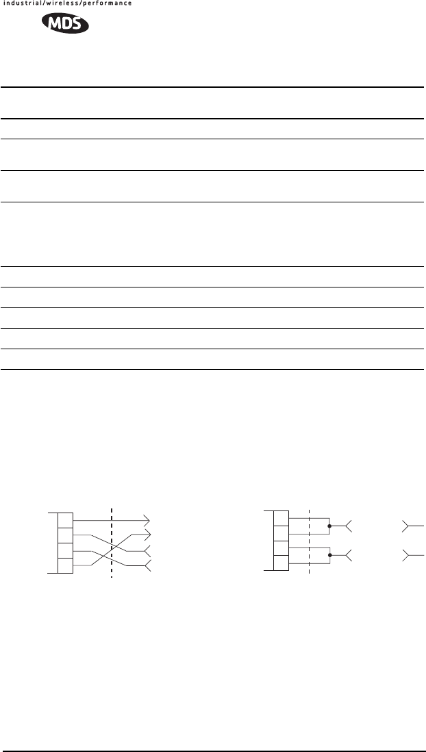
Table 4 Notes:
•RXD+/RXA and RXD–/RXB are data sent into the radio to be transmitted out
•RXD+/RXA is positive with respect to RXD–/RXB when the line input is a “0”
•TXD+/TXA and TXD–/TXB are data received by the radio and sent to the connected
device
•TXD+/TXA is positive with respect to TXD–/TXB when the line output is a “0”
Invisible place holder
Figure 12. EIA-422/485 Wiring Schemes
(Consult external device manual for its detailed pin information)
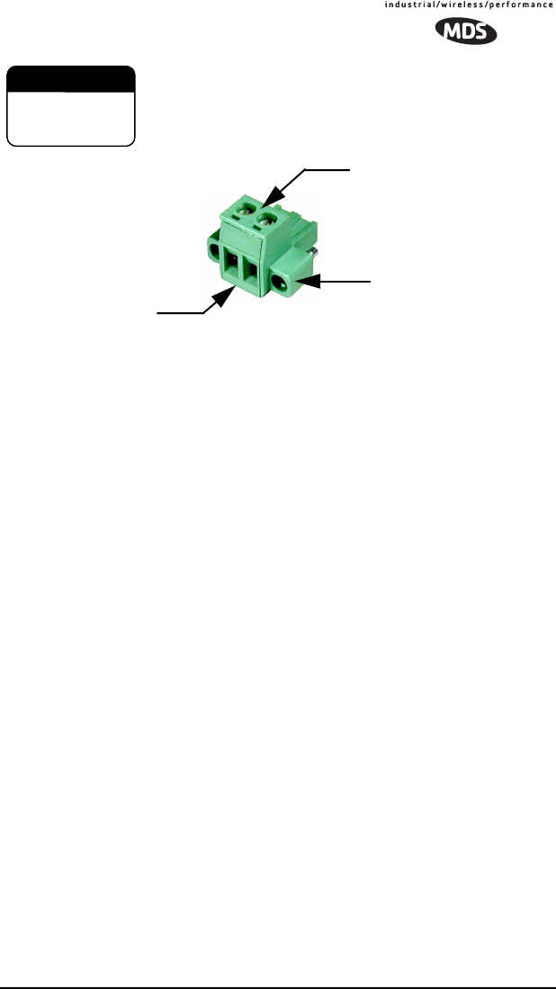
DC Power Connector (J3)
This connector accepts operating power for the transceiver. A wall-style AC
adapter (Part No. 01-3862A02) is recommended for this service.
DC connection is made with a 2-pin polarized plug, MDS Part No.
73-1194A39. Be sure to observe proper polarity. The left terminal is
positive (+) and the right is negative (-). (See Figure 13).
Table 4. DATA connector pin descriptions—RS/EIA-485 Mode
Pin
Number Input/
Output Pin Description
1—Reserved — Do not connect.
2 OUT TXD+/TXA — Non-inverting driver output. Supplies data to
the connected device.
3INRXD+/RXA — Non-inverting receiver input. Accepts data
from the connected device.
4INSleep Mode Input — A ground on this pin turns off most cir-
cuits in a remote radio. This allows for greatly reduced power
consumption, yet preserves the radio’s ability to be brought
quickly back on line. See “Sleep Mode Operation (Remote
units only)” on Page 31 for details.
5INGround — Connects to ground (negative supply potential).
6 -- Reserved — Do not connect.
7INRXD–/RXB — Inverting receiver input.
8 OUT TXD–/TXB — Inverting driver output.
9 -- Reserved — Do not connect.
TXD +
RXD +
2
3
7
RADIO
DATA CONNECTOR
8
RXD –
TXD –
4-WIRE CONNECTIONS
RXD+/TXD+
2
3
7
8
2-WIRE CONNECTIONS
RXD–/TXD–
RADIO
DATA CONNECTOR
EXTERNAL DEVICE
EXTERNAL DEVICE
TXD +
RXD +
RXD –
TXD –
TXD +
RXD +
RXD –
TXD –
MDS 05-xxxxA01, Rev. 01 TransNET OEM 2.4 Integration Guide 15
The transceiver must be used only with negative-ground
systems. Make certain that the polarity of the power
source is correct.
Invisible place holder
Figure 13. DC Power Connector (P/N 73-1194A39)
NOTE: Although the power connector used on the OEM Evaluation Board
resembles those used by some earlier MDS transceivers, such as the MDS
9810 and x710 family, the connectors are not equal and the use of the wrong
plug will provide unreliable connections. Only the power connector shown in
Figure 13 with screw terminals and two retainer screws should be used with
the OEM Evaluation Board.
Jumper Block J1 (DC Power Configuration)
Jumper J1 does not normally require any change by the user. The jumper is
used to configure the board for the proper voltage level applied to the
transceiver module.
Both jumper plugs are normally installed on J1. The plug connecting Pins 3
and 4 may be temporarily removed to insert an ammeter in series with the DC
power line going to the transceiver. This provides a convenient way to
measure the transceiver’s current draw during bench testing.
3.3 Initial Power-Up & Configuration
When all of the cable connections described in Section 3.2 have been made,
the transceiver is ready for initial power-up. Operation begins as soon as
power is applied, and there are no manual adjustments or settings required.
To place the transceiver into operation:
1. Ensure that all cable connections are properly wired and secure. Verify
that no metallic objects are touching the underside of the evaluation board
which might cause a short-circuit.
2. Apply DC power. The GP indicator (CR6) on the transceiver board
should light continuously.
CAUTION
POSSIBLE
EQUIPMENT
DAMAGE
Lead
Screws (2)
Binding
Wire Ports (2)
(Polarity: Left +, Right –)
Retaining
Screws (2)

16 TransNET OEM 2.4 Integration Guide MDS 05-xxxxA01, Rev. 01
3. Using a connected PC terminal, configure the unit with the proper mode
(master or remote), network address and data parameters. See
Configuration Settings below for programming details.
4. Observe the transceiver’s LED indicators for proper operation. Table 5 on
Page 17 shows the functions and normal indications of the LEDs.
5. Verify that the transceiver is transmitting and receiving data (TXD, RXD)
in response to the master station and/or connected terminal device.
Configuration Settings
This section explains how to set the essential operating parameters of the
transceiver. For more information on connecting a PC terminal and preparing
it for use, refer to Section see “PROGRAMMING REFERENCE” on Page
34.
The three essential settings for the transceiver are as follows:
Mode—Master, Remote, or Extension
Network Address—a unique number from 1–65000
Data Interface Parameters—bps, data bits, parity, stop bits
Band—set transceiver to one of its three operating bands
(A, B or C)
Follow these steps to program the transceiver:
1. Set the Mode using the MODE M (Master), MODE R (Remote), or MODE X
(Extension) command. (Note: There can be only one master radio in a
system.)
For Extension (SAF) radios only: If any MODE X radios are used in the
network, SAF must be turned on at the Master station. The MODE X radio
must be programmed with an Extended Address (XADDR). Units that
need to hear the MODE X radio must be programmed with an appropriate
XPRI and/or XMAP value. (See “Simple Extended SAF Network” on
Page 26 for more information.)
2. Set a unique Network Address (1–65000) using ADDR command. Each
radio in the system must have the same network address. Tip: Use the last
four digits of the master station’s serial number to help avoid conflicts
with other users.
3. Set the baud rate/data interface parameters. Default setting is 9600 bps, 8
data bits, no parity, 1 stop bit. If changes are required, use the BAUD xxxxx
abc command where xxxxx equals the data speed (1200–115200 bps) and
abc equals the communication parameters as follows:
a = Data bits (7 or 8)
b = Parity (N for None, O for Odd, E for Even)
c = Stop bits (1 or 2)
NOTE: 7N1, 8E2 and 8O2 are invalid interface parameters.

MDS 05-xxxxA01, Rev. 01 TransNET OEM 2.4 Integration Guide 17
RXD
TXD
DCD
GP
Configuring Multiple Remote Units
In most installations, the Remote radios will be programmed with virtually
the same set of parameters. This process can be streamlined by testing key
pieces of equipment—such as the Master, Remote, and any Extensions—on
a benchtop setup prior to installation. This allows you to test various
configurations in a controlled environment.
Once the evaluation network is working satisfactorily, you can save the
configuration of each unit in a data file on your PC’s hard drive through the
use of TransNET Configuration Software. You can then open the Remote
configuration file and install it in the next Remote radio. The software
prevents you from overwriting unit or other mode-specific parameters.
LED Indicators
The LED indicators are located to the right of the transceiver’s shield cover
(near J3) and show important information about status of the module. The
functions of LEDs are explained in Table 5 below.
NOTE: For the LEDs to function, they must be enabled using the LEDS ON command.
Within 16 seconds of power-up, the following indications will be seen if the
unit has been properly configured and is communicating with another
transceiver:
•GP lamp lit continuously
•DCD lamp lit continuously (if unit is synchronized with another station)
• Remote radio(s) transmitting data (TXD) and receiving data (RXD) with
another station.
Table 5. LED indicator descriptions
LED Name Description
RXD (CR3)
Receive Data
Serial receive data activity. Payload data from con-
nected device.
TXD (CR4)
Transmit Data
Serial transmit data activity. Payload data to con-
nected device.
DCD (CR5)
Data Carrier Detect
Continuous—Radio is receiving/sending synchro-
nization frames
On within 10 seconds of power-up under normal
conditions
GP (CR6)
General Purpose •Continuous—Power is applied to the radio; no
problems detected
•Flashing (5 times-per-second)—Fault indication.
See “TROUBLESHOOTING” on Page 52
•Off—Radio is unpowered or in Sleep mode