GE MDS DS-EL806-24 2.4 GHz TransNet User Manual xxxxA TNET2 4 OEM Body
GE MDS LLC 2.4 GHz TransNet xxxxA TNET2 4 OEM Body
GE MDS >
Contents
- 1. Users Manual Part 1
- 2. Users Manual Part 2
- 3. Users Manual Part 3
- 4. Users Manual Part 4
Users Manual Part 4

MDS 05-xxxxA01, Rev. 01 TransNET OEM 2.4 Integration Guide 33
5. If constant interference is present in a particular frequency zone, it may
be necessary to “lock out” that zone from the radio’s hopping pattern.
The radio includes built-in tools to help users do this. Refer to the
discussion of the SKIP command (Page 49) for more information. In the
USA, a maximum of four zones may be skipped, per FCC rules. Check
the regulatory requirements for your region.
6. Interference can also come from out-of-band RF sources such as paging
systems. Installation of a bandpass filter, such as Part No. 20-2822A02 in
the antenna system may provide relief from this type of interference.
7. Proper use of the RETRY and REPEAT commands may be helpful in areas
with heavy interference.
The RETRY command sets the maximum number of times (1 to 10) that a
radio will re-transmit upstream data over the air. Values greater than 1
successively improve the chances of a message getting through when
interference is a problem.
The REPEAT command sets a fixed number of unconditional
retransmissions for downstream data.
8. The RF power output of all radios in a system should be set for the lowest
level necessary for reliable communications. This lessens the chance of
causing unnecessary interference to nearby systems and keeps power
consumption to a minimum.

34 TransNET OEM 2.4 Integration Guide MDS 05-xxxxA01, Rev. 01
10.0 PROGRAMMING REFERENCE
All programming and control of the transceiver is performed through a PC
terminal connected to the radio or the Evaluation Board DIAG connector.
There are no manual adjustments or jumper settings used for configuration.
This section explains how to establish terminal communication, and provides
a complete list of user commands.
10.1 Programming Methods
Terminal Interface Mode
A PC may be used by operating it in a basic terminal mode (e.g., a
HyperTerminal session) and entering the radio commands listed in the tables
contained in this section. The PC must be connected to the radio via its 16-pin
header connector, or, if using the Evaluation Board, via the modular
diagnostics connector. In the latter case, an RJ-11 to DB-9 Adapter Cable
(Part No. 03-3246A01) is required. A cable of this type may be constructed
using the information shown in Figure 10 on Page 11.
Once a PC terminal is connected, communication (baud rate) is automatically
established through the command interface. To access the command
interface, press the ESCAPE key, followed by one or more ENTER keystrokes
(delivered at about half-second intervals), until the “>” prompt is displayed.
NOTE: The diagnostic interface uses 8 data bits, 1 stop bit, and no parity. It automati-
cally configures itself to function at 1200, 2400, 4800, 9600, 19200, 38400,
57600, and 115200 bps.
If the DLINK setting is ON, the interface will start out in Diagnostic Link mode.
This is a special protocol used to support Network-Wide Diagnostics. The pro-
cess described in the paragraph above causes the radio to exit diagnostic link
mode and enter command mode. If there is no input in command mode for 5
minutes, the interface will revert back to diagnostic link mode.
PC-Based Configuration Software
The Windows™-based TransNET Configuration Software
(P/N 06-4059A01) is designed for use with the OEM Transceiver. This
software provides access to all of the radio’s capabilities with the benefit of
context-sensitive help. The program is shipped as part of the TransNET
Support Package CD included with every order.
10.2 User Commands
A series of tables begin on the next page listing the various user commands
for the OEM transceiver. The tables provide abbreviated command
descriptions. Complete descriptions follow in Section 9.3.

MDS 05-xxxxA01, Rev. 01 TransNET OEM 2.4 Integration Guide 35
Entering Commands
The proper procedure for entering commands is to type the command,
followed by an keystroke. For programming commands, the
command is followed by , the appropriate information or values, and
then .
Table 11. Network Configuration—Master Station
COMMAND DESCRIPTION
BAND [abc]
Details, page 41 Selects which of three frequency ranges the
transceiver will operate in.
BUFF [ON, OFF]
Details, page 42 ON = Seamless data
OFF = Fast byte throughput.
FEC [ON, OFF]
Details, page 44 Sets/disables FEC
(Forward Error Correction) setting.
HOPTIME [7, 28]
Details, page 44 Displays hop-time or sets it to 7 or 28 ms.
REPEAT [0–10]
Details, page 47 Sets/displays the fixed downstream re-send
count.
RETRY [0–10]
Details, page 47 Sets/displays the maximum upstream re-send
count for ARQ (Automatic Repeat Request)
operation
SAF [ON, OFF]
Details, page 49 Enables/disables the store-and-forward func-
tion for the network controlled by this Master
unit.
SKIP [NONE, 1...8]
Details, page 49 Skip one or more frequency zones
Table 12. Network-Wide Diagnostics
Command Description
DLINK [xxxxx/ON/OFF]
Details, page 43 Controls operation of diagnostic link function.
DTYPE [NODE/ROOT]
Details, page 44 Set radio’s operational characteristics for net-
work-wide diagnostics
ENTER
SPACE
ENTER

36 TransNET OEM 2.4 Integration Guide MDS 05-xxxxA01, Rev. 01
Table 13. Operational Configuration—Set/Program
Command Description
ADDR [1–65000]
Details, page 40
Program network address
AMASK [0000 0000–FFFF FFFF]
Details, page 41 Sets alarm response.
Default: FFFF FFFF
ASENSE [HI/LO]
Details, page 41 Sense of the radio’s alarm output in the
EIA-232 mode. Default: Alarm present = HI.
BAND [abc]
Details, page 41 Selects which of three frequency ranges the
transceiver will operate in.
BAUD [xxxxx abc]
Details, page 41 Data communication parameters
CODE [NONE, 1…255]
Details, page 42 Select the security/encryption setting in the
radio.
CTS [0–255]
Details, page 43 CTS delay in milliseconds.
(A value of 0 returns CTS immediately)
CTSHOLD [0–60000]
Details, page 43 “Hold time” that CTS is present following last
character from DATA port.
DEVICE [DCE, CTS KEY]
Details, page 43
Device behavior:
DCE (normal) or CTS Key
LEDS [ON, OFF]
Details, page 45 Enables/disables transceiver LEDs
MODE [M, R, X]
Details, page 45 Operating mode:
where M = Master, R = Remote
OWM [xxxxx]
Details, page 46 Owner’s message, or alternate message (30
characters maximum)
OWN [xxxxx]
Details, page 46 Owner’s name, or alternate message
(30 characters maximum)
PORT [RS232, RS485]
Details, page 46 Data port (DATA connector) interface signal-
ing mode: RS232 or RS485
PWR
Details page 47 Forward power-output setting in dBm
REPEAT [0–10]
Details, page 47 Forward power output in dBm.
RXTOT [NONE, 0–1440]
Details, page 48 Maximum duration (in minutes) before
time-out alarm. Default is OFF.

MDS 05-xxxxA01, Rev. 01 TransNET OEM 2.4 Integration Guide 37
RTU [ON, OFF, 0-80]
Details, page 48 Enable or Disable unit’s built-in RTU simula-
tor. Default is OFF. Set RTU address between
zero and 80.
SLEEP [ON, OFF]
Details, page 50 Enable or Disable the radio’s Sleep mode
function.
UNIT [10000–65000]
Details, page 51 Unit address used for network-wide diagnos-
tics. (Unique within associated network.)
XADDR [0–31]
Details, page 51 This unit’s Extended address
Typically, the Master is set to zero (0).
XPRI [0–31]
Details, page 51 Address of the primary Extended radio unit
(Extension).
XMAP [00000000-FFFFFFFF]
Details, page 51
Included Extended units in MODE X. (Exten-
sions and Remotes only).
XRSSI [NONE, –40...–120]
Details, page 51 Minimum RSSI level required to preserve syn-
chronization with a non-primary radio.
(Only meaningful when XPRI is not NONE)
ZONE CLEAR
Details, page 51 Reset zone data statistics
Table 14. Operating Status—Display Only
Command Description
ADDR
Details page 40 Network address
AMASK
Details page 41 Alarm mask (response)
ASENSE
Details page 41 Current sense of the alarm output.
BAND
Details page 41 Shows which of three frequency ranges the
transceiver is set to operate in (A, B, or C)
BAUD
Details page 41 Data communication parameters. Example:
BAUD 9600 8N1
BUFF
Details page 42 Data buffering mode: ON = seamless data,
OFF = fast byte throughput
CODE
Details page 42 Security/encryption operational status.
“NONE” (Inactive), or “ACTIVE”
Table 13. Operational Configuration—Set/Program (Continued)
Command Description

38 TransNET OEM 2.4 Integration Guide MDS 05-xxxxA01, Rev. 01
CTS
Details page 43 CTS delay in milliseconds (0–255 ms)
CTSHOLD
Details page 43 “Hold time” that CTS is present following last
character from DATA port.
DEVICE
Details page 43 Device behavior
Alternatives: DCE and CTS KEY
HOPTIME
Details page 44 Hop-time value in milliseconds (ms).
HREV
Details, page 45 Hardware revision level
LEDS [ON, OFF]
Details, page 45 Enables/disables transceiver LEDs
MODE
Details page 45 Current operating mode:
M = Master
R = Remote
X = Extension (Repeater)
OWM
Details page 46 Owner’s message or site name
OWN
Details page 46 Owner’s name or system name
PORT
Details page 46 Current data port (DATA connector) interface
signaling mode: RS232 or RS485
PWR
Details page 47 Show forward power-output setting in dBm
REPEAT
Details page 47 The fixed downstream re-send count.
RETRY
Details page 47 The maximum upstream re-send count for
ARQ (Automatic Repeat Request) operation.
SAF
Details page 49 The store-and-forward function status.
SKIP
Details page 49 Table of frequency zones programmed to be
skipped
RSSI
Details page 48 Received signal strength indicator (dBm).
Unavailable at Master unless SETUP is
enabled.
Table 14. Operating Status—Display Only (Continued)
Command Description

MDS 05-xxxxA01, Rev. 01 TransNET OEM 2.4 Integration Guide 39
RXTOT
Details page 48 The amount of time (in seconds) to wait before
issuing a time-out alarm.
RTU
Details page 48 RTU simulator’s operational status (ON/OFF)
SAF
Details page 49 Store-and-forward mode status in this unit.
(ON/OFF)
SER
Details page 49 Serial number of radio
SHOW PWR
Details page 49 Show measured RF output power in dBm
SHOW SYNC
Details page 49 Information on synchronization source and
depth
SKIP
Details page 49 Frequency zones that are skipped
SLEEP
Details page 50 Radio’s Sleep Mode setting.
(At Remotes Only)
SREV
Details page 50 Transceiver firmware revision level
STAT
Details page 50 Current alarm status
TEMP
Details page 50 Transceiver’s internal temperature (°C)
UNIT
Details page 51 Programmed unit address for
network-wide diagnostics
XADDR
Details page 51 This unit’s Extended address
XPRI
Details page 51
Address of the primary Extended radio unit
(Extension).
XMAP
Details page 51
Included Extended units in MODE X. (Exten-
sions and Remotes only).
XRSSI
Details page 51 Minimum RSSI level required to preserve syn-
chronization with a non-primary radio. (Only
meaningful when XPRI is not NONE)
Table 14. Operating Status—Display Only (Continued)
Command Description

40 TransNET OEM 2.4 Integration Guide MDS 05-xxxxA01, Rev. 01
10.3 Detailed Command Descriptions
The essential commands for most applications are Network Address (ADDR),
Mode (MODE), and Baud Rate (BAUD). However, proper use of the additional
commands allows you to tailor the transceiver for a specific use, or to conduct
basic diagnostics on the radio. This section gives more detailed information
for the commands listed above in section 9.2.
Most of the commands below can be used in two ways. First, you can type
only the command name (for example, ADDR) to view the currently
programmed data. Second, you can set or change the existing data by typing
the command, followed by a space, and then the desired entry (for example,
ADDR 1234). In the list below, allowable programming variables, if any, are
shown in brackets [ ] following the command name.
ADDR [1–65000]
This command sets or displays the radio’s network address. The network
address can range from 1 to 65000.
A network address must be programmed at the time of installation and must
be common across each radio in a given network. Radios are typically
shipped with the network address unprogrammed, causing the address to
display as NONE. If the address is not set (or is set to a wrong value) it leaves
the system in an invalid state, preventing operation and generating an alarm.
NOTE: It is recommended that the last four digits of the master radio’s serial number
be used for the network address. This helps avoid conflicts with other users.
Table 15. Diagnostic and Test Functions
Command Description
KEY
Details, page 45 Enables the transmitter test.
(Radio must be in Setup mode.)
DKEY
Details, page 44 Turns off the transmitter test.
(Radio must be in Setup mode.)
TX [xxxx]
Details, page 50 Set/display transmit test frequency.
(Radio must be in Setup mode.)
RX [xxxx]
Details, page 48 Set/display receive test frequency.
(Radio must be in Setup mode.)
SETUP
Details, page 49 Enables Setup mode. Times out after 10 min-
utes. Press “Q” to quit.
ZONE DATA
Details, page 51 Zone data statistics
ZONE CLEAR
Details, page 51 Clears the Zone Data log

MDS 05-xxxxA01, Rev. 01 TransNET OEM 2.4 Integration Guide 41
AMASK [0000 0000–FFFF FFFF]
This command sets the alarm bits that cause the alarm output signal to be
triggered. The PWR LED will still flash for all alarms, but the alarm output
signal will only be activated for those alarms that have the corresponding
mask bit set. The hex value for the mask aligns directly with the hex value for
the ALARM command. The default is FFFF FFFF. Through proper use of the
AMASK command, it is possible to tailor the alarm response of the radio.
Contact the factory for more information on configuring the alarm mask.
ASENSE [HI/LO]
This command is used to set the sense of the radio’s alarm output at Pin 3 of
the 16-pin header connector. The default setting is HI which means an alarm
exists when an RS-232 high is on Pin 3.
BAND [abc]
The BAND command is used to select one of three frequency ranges that the
transceiver will operate in (A, B, or C). All transceivers in a given network
must have the same band setting or communication will not be possible.
Conversely, radios may be set to different bands to enable up to three separate
radio networks to operate in the same vicinity, without cross-network
interference.
Each frequency band is approximately 26 MHz wide, and contains eight
“zones” within. These zones are described in more detail under the ZONE
DATA command (see Page 51). The frequency ranges for each band are as
follows:
Band A: 2.4016–2.4270 GHz
Band B: 2.4272–2.4526 GHz
Band C: 2.4528–2.478.2 GHz
BAUD [xxxxx abc]
This command sets or displays the communication attributes for the normal
payload communications through the DATA port. The command has no effect
on the RJ-11 DIAG(NOSTICS) port.
The first parameter (xxxxx) is baud rate. Baud rate is specified in
bits-per-second and must be one of the following speeds: 1200, 2400, 4800,
9600, 19200, 38400, 57600, or 115200. At baud rates of 19200 bps or less,
the radio can support unlimited continuous data transmission at any hop rate.
The second parameter of the BAUD command (abc) is a 3-character block
indicating how the data is encoded. The following is a breakdown of each
character’s meaning:
a = Data bits (7 or 8)
b = Parity (N for None, O for Odd, E for Even)
c = Stop bits (1 or 2)
The factory default setting is 9600 baud, 8 data bits, no parity, 1 stop bit
(Example: 19200 8N1).

42 TransNET OEM 2.4 Integration Guide MDS 05-xxxxA01, Rev. 01
NOTE: 7N1, 8O2, and 8E2 are invalid communication settings and are not supported
by the transceiver.
BUFF [ON, OFF]
This command sets or displays the received data handling mode of the radio.
The command parameter is either ON or OFF. (The default is OFF.) The
setting of this parameter affects the timing of received data sent out the DATA
connector. Data transmitted over the air by the radio is unaffected by the
BUFF setting.
If data buffering is set to OFF, the radio will operate with the lowest possible
average latency. Data bytes are sent out the DATA port as soon as an incoming
RF data frame is processed. Average and typical latency will both be below
10 ms, but idle character gaps may be introduced into the outgoing data flow.
If data buffering is ON, the radio will operate in a seamless mode. That is, data
bytes will be sent over the air as quickly as possible, but the receiver will
buffer the data until the entire packet has been collected. The delay introduced
by data buffering is variable and depends on message size and the number of
retransmissions required, but the radio will not create any gaps in the output
data stream. This mode of operation is required for protocols such as
MODBUS™ that do not allow gaps in their data transmission.
Seamless mode (BUFF ON) is intended only for applications where the
message size is 256 characters or less. Enforcement of this rule is left up to
the user. If more than 256 characters are transmitted data delivery will not be
seamless and data may be lost.
Changes to the BUFF setting may only be made at the master radio. This is
because the master radio broadcasts the buffer setting for the entire network.
At remote radios, the buffer setting may be read when the radio is in
synchronization with the master, but it may not be changed.
CODE [NONE, 1…255]
The CODE command is used to select or display the security/encryption
setting in the radio.
The default is CODE NONE. Setting CODE to a value other than NONE
provides an extra level security beyond that provided by the Network Address
(ADDR). The disadvantage is increased complexity in managing the network.
The CODE command takes an argument 1…255, or “NONE”. Entering CODE
without an argument will display either “NONE” or “ACTIVE”. ACTIVE
means that security/encryption has been enabled, but the radio will not
display the security argument.
When a CODE value is active, all radios in the system must use the same code
value. If the code value is not properly programmed, a remote radio will not
synchronize with the master.
CAUTION: Record the CODE value and store it in a safe place. If the code is
later forgotten, and a unit is to be added to the system, all radios in the
network must be set to NONE and then reprogrammed to a new value.

MDS 05-xxxxA01, Rev. 01 TransNET OEM 2.4 Integration Guide 43
CTS [0–255]
The CTS (clear-to-send) command sets or displays the timer value associated
with the CTS line response. The command parameter ranges from 0 to 255
milliseconds.
For DCE operation, the timer specifies how long to wait after the RTS line
goes high before asserting the CTS line. A timer value of zero means that the
CTS line will be asserted immediately following the assertion of RTS.
For CTS Key operation (see the DEVICE command), the timer specifies how
long to wait after asserting the CTS line before sending data out the DATA
port. A timer value of zero means that data will be sent out the data port
without imposing a key-up delay. (Other delays may be in effect from other
radio operating parameters.)
CTSHOLD [0–60000]
Used in DEVICE CTS KEY mode, this command sets the amount of time in
milliseconds that CTS remains present following transmission of the last
character out the RXD pin of the DATA port. This “hold time” can be used to
prevent squelch tail data corruption when communicating with other radios.
The CTSHOLD setting can range from 0 to 60000 (i.e., 60 seconds). The
default value is 0, which means that CTS will drop immediately after the last
character is transmitted. If the command is entered when the radio is in
DEVICE DCE mode, the response CTSHOLD N/A will be displayed.
DEVICE [DCE, CTS KEY]
The DEVICE command sets or displays the device behavior of the radio. The
command parameter is either DCE or CTS KEY.
The default selection is DCE. In this mode, CTS will go high following RTS,
subject to the CTS programmable delay time. Keying is stimulated by the
input of characters at the data port. Hardware flow control is implemented by
dropping the CTS line if data arrives faster than it can be transmitted.
If CTS KEY is selected, the radio is assumed to be controlling another radio,
such as in a repeater or tail-end link system. The RTS line is ignored and the
CTS line is used as a keyline control for the other radio. CTS is asserted
immediately after the receipt of RF data, but data will not be sent out the DATA
port until after the CTS programmable delay time has expired. (This gives the
other radio time to key.)
Following transmission of the last byte of data, CTS will remain asserted for
the duration specified by the CTSHOLD command. CTSHOLD should be set
sufficiently high.
DLINK [xxxxx/ON/OFF]
DLINK ON enables use of Diagnostic Link mode and establishes it as the
default protocol on the RJ-11 DIAG port. Diagnostic Link mode is a special
protocol used to support Network-Wide Diagnostics. DLINK must be set to
ON to support connection to InSite or to support chained diagnostics between
radio networks. DLINK OFF disables this feature. The default setting is ON.

44 TransNET OEM 2.4 Integration Guide MDS 05-xxxxA01, Rev. 01
The following DLINK baud rates selections are allowed:
• 1200 • 4800 • 9600 • 19200 (default)
• 38400 • 57600 • 115200
Example: DLINK 4800 sets the RJ-11 DIAG port to operate at 4800 bps when
diagnostics is “closed”. This setting will not affect the port’s autobaud
operation. Use only of DLINK ON, will enable the use 19200 or the most
recently programmed value. The default is DLINK 19200 and DLINK ON.
NOTE: The same baud rate must be entered into the InSite Equipment List’s BAUD
field.
NOTE: The DLINK rate must match the rate of any connected device to the diagnostic
port. This may be either another radio’s diagnostic port, the InSite computer, or
another data link device that eventually connects to the InSite computer.
DKEY
Disables the transmitter when it is keyed. See also KEY command.
DTYPE [NODE/ROOT]
The DTYPE command specifies the radio’s operational characteristics for
network-wide diagnostics. The transceiver uses the following types:
•NODE–The most common setting, and the default. This is the basic
system radio device-type. Typically, the radio network is comprised of
nodes and one root. Intrusive diagnostics can originate from any node.
However, non-intrusive diagnostics can only be conducted from the
root node.
•ROOT–Always one, and only one, per network (including units
associated through Extension units.) The root is the focal point of
network-wide diagnostics information. Intrusive diagnostics can
originate from any radio, including the root. However, the root is the
only radio through which non-intrusive diagnostics can be conducted.
FEC [ON, OFF]
This command is used to view the FEC setting, or turn it on or off. The default
setting is FEC ON. (It needs to be turned off when throughputs exceed
57,600 bps.) FEC is set at the master and is automatically passed on to all of
the remotes in a network.
Setting FEC to ON improves sensitivity at the cost of reduced throughput.
Typical SCADA/telemetry applications use low data rates and, as such, the
FEC setting is normally transparent to them.
HOPTIME [7, 28]
The HOPTIME command is used to set or display the hop-time setting. The
command is a digit corresponding to the hop-time setting in milliseconds. The
default HOPTIME setting is 7. A setting of 28 must be used when throughputs
exceed 57,600 bps.

MDS 05-xxxxA01, Rev. 01 TransNET OEM 2.4 Integration Guide 45
Changes to the HOPTIME setting may only be made at the master radio. (This
is because the Master radio establishes the hop-time setting for the entire
network.) At remote radios, the hop-time setting may be read when the radio
is in synchronization with the master, but it may not be changed.
INIT
The INIT command is used to reset the radio’s operating parameters to the
factory defaults listed in Table 16 on Page 46. This may be helpful when
trying to resolve configuration problems that resulted from the entry of one
or more improper command settings. If you are unsure of which command
setting caused the problem, this command allows you to get back to a known
working state.
NOTE: Caution should be exercised when using the INIT command on radios in a sys-
tem employing the Store-and-Forward feature. Settings relating to the use of
Extension services will be lost and will need to be re-entered. Inventory and
record the settings for XADDR, XPRI and XMAP before using the INIT com-
mand.
SPECIAL NOTE: Installing firmware of Revision 2.0 or later into a radio with Revi-
sions 1.x firmware will preserve the radio’s compatibility with other radios run-
ning Revision 1.x firmware. If updating the radio’s firmware is part of a
system-wide upgrade, the last step should be to use the INIT command at the
Master station. Use of the INIT command causes the changes shown in
Table 16 on Page 46 to be applied
HREV
Shows the Hardware revision of the radio.
KEY
Enables the transmitter. (Radio must be in Setup mode.) See also DKEY
command.
LEDS [ON, OFF]
This command is used to view the LED setting, or to enable/disable LED
operation. In power-critical applications (battery/solar powered sites, for
example), it may be desirable to turn off the LEDs.
MODE [M, R, X]
The MODE command sets or displays the operating mode of the radio. A
master radio is set by MODE M; a remote set by MODE R, and an Extension is
set by MODE X.
All units default to remotes; other modes must be specifically programmed
with the MODE command.
If MODE X is used, the MODE X radio should be programmed with an
Extended Address (XADDR). Units that need to hear this MODE X radio must
be programmed with an appropriate XPRI and/or XMAP value.

46 TransNET OEM 2.4 Integration Guide MDS 05-xxxxA01, Rev. 01
OWM [xxxxx]
The OWM command sets or displays an optional owner’s message, such as the
system name. The entry can contain up to 30 characters.
OWN [xxxxx]
The OWN command sets or displays an optional owner’s name, such as the
site name. The entry can contain up to 30 characters.
PORT [RS232, RS485]
Select or identify the current data interface signaling mode: RS232 or RS485.
This is the port though which the payload data will pass. Pin descriptions for
EIA-232 are on Page13 and EIA-485 can be found on Page13. Note: This
command will always show TTL if the radio is only equipped for TTL
service—see model number configuration code on Page 3.
PWR [17–21]
This command displays or sets the desired RF forward output power setting
of the radio. The PWR command parameter is specified in dBm and can range
from 20 dBm through 27 in 1 dBm steps. The default setting is 27 dBm (0.5
watt). To read the actual (measured) power output of the radio, use the SHOW
PWR command.
In the USA, maximum allowable power is governed by FCC limits on
Effective Isotropic Radiated Power output (EIRP). The EIRP limit of
+36 dBm means that any user with a net antenna gain greater than 10 dBi
must decrease the PWR setting accordingly.
Table 16. INIT Command Generated Defaults
Parameter Default Setting Corresponding
Command
For all radios
Device operation DCE DEVICE DCE
CTS delay 0
(CTS is continuously asserted) CTS 0
CTS hold-time 0CTSHOLD 0
DATA Interface port • 9600 baud
• 8 data bits
• none (no parity)
• 1 stop bit
BAUD 9600 8N1
Alarm Mask FFFF FFFF AMASK
Alarm Output Sense RS-232 High (+5.0 Vdc) ASENSE
RX Time-out-Timer None/Disable RXTOT
Transmitter
test frequency 2.4xx GHz TX xxx

MDS 05-xxxxA01, Rev. 01 TransNET OEM 2.4 Integration Guide 47
REPEAT [0–10]
The REPEAT command affects “downstream” data. The command causes a
Master or Extension to always repeat transmissions for the specified number
of times (range is 0 to 10; default selection is 3). Unlike the RETRY command,
there is no acknowledgment that a message has been received. To display the
current setting, use the REPEAT command without entering a value.
RETRY [0–10]
The RETRY command affects upstream data. The command selects, or
displays, the maximum number of times (0 to 10) that a remote radio will
re-transmit data. The default setting is 10.
This command is associated with ARQ (Automatic Repeat Request)
operation of the radio and is intended for use in areas with heavy radio
interference.
When the RETRY command is issued without parameters, the maximum
retransmission count is shown. A value of 0 represents no retries, while
values of 1 or greater successively improve the chance of data delivery in
spectrally harsh environments (at the expense of possibly increased latency).
The RETRY value is only settable at the Master. It is readable by a
synchronized Remote.
Receiver
test frequency 2.4xx GHz RX xxx
Sleep Enable OFF SLEEP OFF
Data Port Setting RS/EIA-232 PORT RS232
Primary Extension
Radio Address 0 (Master) XPRI 0
Synchronization
Source Map None XMAP 0
Extended Address 0XADDR 0
For MASTER radios
Skipped frequencies None (radio will hop across all
frequencies) SKIP NONE
Hop-time 7 ms HOPTIME 7
Buffer mode OFF BUFF OFF
Retry Count 10 (max. 10 repeats for ARQ) RETRY 10
Repeat Count 3 (downstream repeats) REPEAT 3
Forward Error
Correction ON FEC ON
Table 16. INIT Command Generated Defaults (Continued)
Parameter Default Setting Corresponding
Command

48 TransNET OEM 2.4 Integration Guide MDS 05-xxxxA01, Rev. 01
RSSI
This command displays the radio’s Received Signal Strength Indication in
dBm (decibels relative to 1 mW). The output can range from –40 dBm to
–120 dBm. Command availability and results depend on the mode of
operation (master or remote). The closer to 0 dBm, the stronger the signal,
thus a reading of –70 dBm is stronger than –80 dBm.
For a remote radio, under normal operation, RSSI is based on the average
signal strength of the SYNC message received in each of the eight frequency
zones. (RSSI is sampled each time a SYNC message is received.) When using
the RSSI reading to align a directional antenna, it is important to make
changes slowly so that the RSSI reading will provide meaningful results. It
will take several seconds to indicate a change in signal level. The radio stays
in RSSI mode until is pressed.
For a master radio, under normal operation, entering the RSSI command
causes the response NOT AVAILABLE to be returned. This is because a master
is normally receiving signals from several remote stations and an RSSI
reading would be continually changing. The only exception is when the
SETUP command has been asserted. This disables hopping and allows
reading a “raw” RSSI signal level in real time from a master or remote radio.
NOTE: RSSI readings will not indicate signals stronger than –40 dBm.
RTU [ON, OFF, 0-80]
This command re-enables or disables the radio’s internal RTU simulator,
which runs with proprietary polling programs such as poll.exe and rsim.exe.
The internal RTU simulator is available whenever a radio has diagnostics
enabled. This command also sets the RTU address that the radio will respond
to.
The internal RTU can be used for testing system payload data or pseudo bit
error rate (BER) testing. It can be helpful in isolating a problem to either the
external RTU or the radio. The default RTU setting is OFF.
RX [xxxx]
This command sets or displays the test receive frequency used in place of
hopping when the radio is in SETUP mode. The test receive frequency can be
reprogrammed to any value between 2.4016 GHz and 2.4782 GHz, inclusive.
The factory default setting is 2.42420 GHz.
RXTOT [NONE, 0–1440]
This command sets or displays the amount of time (in minutes) to wait for the
next received data packet before issuing a receiver time-out alarm. The
default setting is NONE.
ENTER

MDS 05-xxxxA01, Rev. 01 TransNET OEM 2.4 Integration Guide 49
SAF [ON, OFF]
This command enables/disables the operation of the Store-and-Forward
services. It can be set only at the network’s Master station, but will effect all
radios in the associated network. The default setting is OFF. See related
commands: “XADDR [0–31]” on Page 51, “XPRI [0–31]” on Page 51, and
“XMAP [00000000-FFFFFFFF]” on Page 51.
SETUP
This command sets up the transceiver for checking antenna SWR or trans-
mitter power with external measuring equipment. Do not use this mode
during normal operation.
When the SETUP command is entered, the prompt changes to SETUP>, and:
• Hopping is disabled.
• Synthesizer frequencies are reset to the test frequencies specified by the
TX and RX commands described earlier.
• The radio can be keyed using the KEY command. DKEY is used to unkey
the radio. (If the radio is left in a keyed state it is automatically unkeyed
after several minutes.)
• The RSSI is sampled in a raw, continuous fashion regardless of whether
the unit is a master or a remote.
Entering Q or QUIT returns the system to normal operation.
A timer keeps the Setup mode from accidentally leaving the system disabled.
After 10 minutes the system behaves as if Q or QUIT had been entered,
returning to normal operation.
SER
Displays the Serial Number of the radio.
SHOW PWR
The SHOW PWR command displays the actual (measured) RF power output
in dBm. Unlike the PWR command, this command shows the actual level
being measured, not the programmed RF power setting.
SHOW SYNC
When used at a Remote station, this command will display Extended Address
and Unit Address of the Master or Extension radio to which the Remote is
synchronized. The network depth at the remote, defined as the number of
downstream links from the Master, is displayed in parentheses.
SKIP [NONE, 1...8]
This command sets or displays which, if any, of the eight 3.2 MHz-wide
zones will be skipped from the radio’s hopping sequence. Skipping zones is
one way of dealing with constant interference on one or more frequencies.
See “DEALING WITH INTERFERENCE” on Page 32 for more information
on dealing with interference.

50 TransNET OEM 2.4 Integration Guide MDS 05-xxxxA01, Rev. 01
The command parameter is either the keyword NONE or an undelimited string
of up to four digits where each digit 1...8 represents a corresponding zone to
skip. (For zone parameter input, the digits can appear in any order and can be
optionally separated by a blank space.) The SKIP command is display-only at
remote radios. (Remotes must be synchronized with the master radio to
display the skip status.)
In the USA, a maximum of four zones may be skipped, per FCC rules. Check
the regulatory requirements for your region before deleting zones.
SLEEP [ON, OFF]
This command is used to set or display the radio’s Sleep Mode setting. The
default setting is SLEEP OFF. When this mode is enabled (ON), a ground or
logic low on Pin 6 of the 16-pin header connector (J3) suspends all normal
radio functions, and power consumption is reduced to approximately 8 mA.
The radio remains in this state until the low is removed. This function cannot
be turned on for a Master or Extension radio.
SREV
This command displays the version of the firmware currently loaded into the
transceiver.
A display of 06-4040A01, 2.0.0 is an example of the firmware version
identifier—part number followed by release/version number.
STAT
This command is used to check the alarm status of the radio. If no alarms
exist, the message NO ALARMS PRESENT is returned.
If an alarm does exist, a two-digit alarm code (00–31) is displayed and the
event is identified as a “Major” or “Minor” alarm. A brief description of the
event is also given.
If more than one alarm exists, the word MORE appears, and additional alarms
may be viewed by pressing the key. Detailed descriptions of the
alarm codes are provided in Table 17 on Page 54.
TEMP
This command displays the internal temperature of the transceiver in degrees
Celsius. (Note that the radio is specified to operate in an environment between
–30 C° and +60 C°). This internal reading may be higher than the outside
temperature by several degrees.
TX [xxxx]
This command sets or displays the test transmit frequency used in place of
hopping whenever the radio is in Setup mode. The test transmit frequency can
be reprogrammed to any value between 2.4016 GHz and 2.4782 GHz,
inclusive. The factory default setting is 2.42420 GHz.
ENTER

MDS 05-xxxxA01, Rev. 01 TransNET OEM 2.4 Integration Guide 51
UNIT [10000–65000]
This command sets the unit addressing for network-wide diagnostics. The
unit address is factory programmed to the last four digits of the serial number.
If re-programmed in the field, the entry must consist of five digits between
10000 and 65000.
XADDR [0–31]
Display or program the Extended Address of this radio that will serve as a
common address for the sub-network synchronized to this Master or
Extension. This value can be listed in the XPRI parameter of associated
Extension or Remote radios to allow them to synchronize to this radio. We
recommend setting the Master to zero (0). It is easy to remember, and is the
default address when the INIT command is used. (Programmed only in
Master and Extension radios.)
XMAP [00000000-FFFFFFFF]
XMAP is a 32-bit hex entry where the least significant bit represents XADDR
0 and the most significant bit represents XADDR 31. The full 32-bit hex
value represents the entire list of extensions with which the radio will be
allowed to communicate. (Remotes and Extensions only.)
This parameter is easily programmed through the TransNET Configuration
Software’s Store and Forward Settings panel.
XPRI [0–31]
Display or program the extended address of a primary radio with which this
radio will attempt to synchronize and communicate. A setting of NONE will
allow the unit to synchronize with any Master or Extension in the XMAP list.
(Parameter only meaningful for a Remote or Extension.)
XRSSI [NONE, –40...–120]
The XRSSI command is used to set the RSSI minimum signal level required
to preserve synchronization with a non-primary Extension radio. This
parameter will be ignored if XPRI is set to NONE.
ZONE CLEAR
The ZONE CLEAR command clears the zone data for all zones in the Zone
Data Log, resetting the count to 0. (Zone data is also cleared automatically
upon reboot.)
ZONE DATA
The transceiver divides its frequency operating spectrum into eight
3.2 MHz-wide zones. (These are the same zones referenced by the SKIP
command described earlier.) Data frame statistics are maintained for each
zone to indicate the transmission quality of data through the network. This
information is useful for identifying zones where significant interference
exists.

52 TransNET OEM 2.4 Integration Guide MDS 05-xxxxA01, Rev. 01
Zone quality information can be accessed using the ZONE DATA command.
For each zone (1–8), it shows you the number of data frames sent, the number
received, and the number received with errors. If an excessive number of
errors are seen in one or more frequency zones, it may indicate interference,
and you should consider “skipping” those zones using the SKIP command.
Note: If a frequency zone has been skipped, all counts for that zone will be
zeros.
The ZONE DATA format is displayed as follows:
1:TX TOTAL 00000000
1:RX TOTAL 00000000
1:RX ERROR 00000000
x:
x:
x:
8:TX TOTAL 00000000
8:RX TOTAL 00000000
8:RX ERROR 00000000
All data is based on payload packets. Incoming network data may be divided
up into multiple packets for over-the-air transfers. The number before the
colon represents the zone. TX TOTAL is the transmit packet total. RX TOTAL is
the receive packet total. RX ERROR is the total number of received packets
with CRC errors. All zone data is reset with the ZONE CLEAR command.
11.0 TROUBLESHOOTING
Successful troubleshooting of the radio system is not difficult, but requires a
logical approach. It is best to begin troubleshooting at the master station, as
the rest of the system depends on the master for polling instructions and
synchronization data. If the master station has problems, the operation of the
entire network will be affected.
When communication problems are found, it is good practice to begin by
checking the simple things. All radios in the network must meet these basic
requirements:
• Adequate and stable primary power
• An efficient and properly aligned antenna system
• Secure connections (RF, data & power)
• Proper programming of the radio’s operating parameters, especially
Mode selection (MODE), Network Address (ADDR), and interface Baud
Rate (BAUD)
• The correct interface between the radio and the connected data
equipment (proper cable wiring, data format and timing).
• In store-and-forward systems there are several areas that must be
carefully evaluated:

MDS 05-xxxxA01, Rev. 01 TransNET OEM 2.4 Integration Guide 53
• Duplicate XADDR values on MODE M and MODE X radios will cause
failures unless the radios are far enough apart to not hear each other.
• Errors in the synchronization qualifiers, XPRI and XMAP, on
corresponding Remote radios.
•SAF must be enabled at the Master
11.1 Alarm Codes
When an alarm condition exists, the transceiver creates an alarm code. These
codes can be very helpful in resolving many system difficulties.
Checking for Alarms—STAT command
To check for the presence of alarms, enter STAT. If no alarms exist, the
message NO ALARMS PRESENT appears at the top of the display.
If an alarm does exist, a two-digit alarm code (00–31) is displayed, and it is
identified as a major or minor alarm. A brief description of the alarm is also
given. Alarm codes and their meanings are listed in Table 17.
If more than one alarm exists, the word MORE appears at the bottom of the
screen; additional alarms can be viewed by pressing .
Major Alarms vs. Minor Alarms
Major alarms report serious conditions that generally indicate a hardware
failure, or other abnormal condition that will prevent (or seriously hamper)
further operation of the transceiver.
With the exception of alarm code 00 (network address not programmed),
major alarms generally indicate the need for factory repair. Contact your
factory representative for further assistance.
Minor alarms report conditions which, under most circumstances, will not
prevent transceiver operation. This includes out-of-tolerance conditions,
baud rate mismatches, etc. The cause of these alarms should be investigated
and corrected to prevent system failure.
ENTER
54 TransNET OEM 2.4 Integration Guide MDS 05-xxxxA01, Rev. 01
Alarm Code Definitions
Table 17 contains a listing of all event codes that may be reported by the
transceiver.Additional alarm codes may be used in future firmware releases
or are used by the factory.
Table 17. Alarm Codes
Alarm
Code Alarm
Type Description
00 Major The network address is not programmed.
01 Major Improper firmware detected for this radio model.
04 Major One or more of the programmable synthesizer loops is reporting
an out-of-lock condition.
08 Major The system is reporting that it has not been calibrated. Factory
calibration is required for proper radio operation.
10 Major The DSP was unable to properly program the system to the ap-
propriate defaults. A hardware problem may exist.
12 Major Receiver time-out alarm.
16 Minor The unit address is not programmed.
17 Minor A data parity fault has been detected on the DATA connector.
This usually indicates a parity setting mismatch between the ra-
dio and the RTU.
18 Minor A data framing error has been detected on the DATA connector.
This may indicate a baud rate mismatch between the radio and
the RTU.
29 Minor RF output power fault detected. (Power differs by more than 2
dB from set level.) Often caused by high antenna system SWR.
Check antenna, feedline and connectors.
30 Minor The system is reporting an RSSI reading below –105 dBm.
31 Minor The transceiver’s internal temperature is approaching an
out-of-tolerance condition. If the temperature drifts outside of
the recommended operating range, system operation may fail.
MDS 05-xxxxA01, Rev. 01 TransNET OEM 2.4 Integration Guide 55
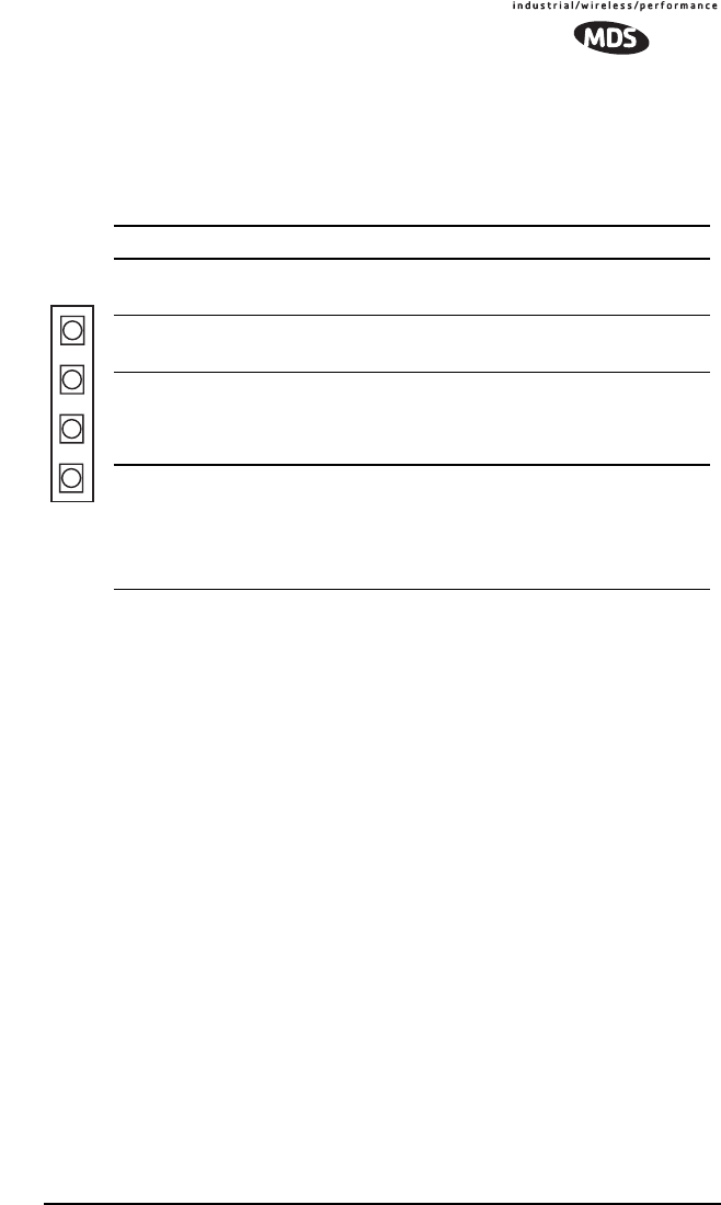
11.2 LED Indicators
The LED indicators on the transceiver board (CR3, CR-4, CR-5 and CR-6)
are an important troubleshooting tool and should be checked whenever a
problem is suspected. Table 18 describes the function of each status LED.
11.3 Troubleshooting Chart
Table 19 provides suggestions for resolving system difficulties that may be
experienced in the radio system. If problems persist, contact the factory for
further assistance. Refer to the inside back cover of this guide for contact
information.
Table 18. LED indicator descriptions
LED Name Description
RXD (CR3)
Receive Data
Serial receive data activity. Payload data from con-
nected device.
TXD (CR4)
Transmit Data
Serial transmit data activity. Payload data to con-
nected device.
DCD (CR5)
Data Carrier Detect
Continuous—Radio is receiving/sending synchroni-
zation frames
On within 10 seconds of power-up under normal
conditions
GP (CR6)
General Purpose •Continuous—Power is applied to the radio; no
problems detected
•Flashing (5 times-per-second)—Fault indication.
See “TROUBLESHOOTING” on Page 52
•Off—Radio is unpowered or in Sleep mode
RXD
TXD
DCD
GP

56 TransNET OEM 2.4 Integration Guide MDS 05-xxxxA01, Rev. 01
11.4 Network-Wide Remote Diagnostics
Diagnostics data from a remote radio can be obtained by connecting a laptop
or personal computer running InSite diagnostics software (V6.6 or later) at
any radio in the network.
Table 19. Troubleshooting chart
Difficulty Recommended System Checks
Unit is
inoperative. a.Check for the proper supply voltage at the transceiver, J3 Pins
5 and11.
b.If using the Evaluation Board, the surface mount fuse may have
opened. Refer to Section 4.3 below for replacement instruc-
tions.
Interference is
suspected. a.Verify that the system has a unique network address. Nearby
systems with the same address will cause interference.
b.Check for interference and lockout any affected zone(s) using
the SKIP command (Page 49).
c.If omnidirectional antennas are used on remote stations, con-
sider changing to directional antennas. This will often limit inter-
ference to and from other stations.
No synchroniza-
tion with master,
or poor overall
performance.
a.Check for secure interface connections at the radio and the
connected device.
b.Check the antenna, feedline and connectors. Reflected power
should be less than 10% of the forward power reading
(SWR ≈ 2:1 or lower).
c.If the remote radio is in synchronization, but performance is
poor, check the received signal strength using the RSSI com-
mand (Page 48). If RSSI is low, it may indicate antenna prob-
lems, or misalignment of directional antenna headings.
d.Verify proper programming of system parameters: mode, net-
work address, data interface baud rate, transmitter power, CTS
delay, etc. For store-and-forward applications, also verify the
following: SAF is ON; extended address is properly pro-
grammed at each extension; remotes are using the proper val-
ues for XPRI and XMAP.
e.Check for alarms using the STAT command (Page 50)
BER is too high.
Data throughput
is spotty.
a.The RETRY and REPEAT commands may be increased to
deal with interference, or decreased to increase throughput
and reduce latency.
b.Try turning on FEC. FEC on gives some coding gain, but
comes at the cost of reduced throughput.
Latency is too
high. a.Reduce the REPEAT count.
b.Turn BUFF OFF. BUFF ON insures that no gaps occur in the
data, but this comes at the cost of increased latency.
c.Make sure HOPTIME is set to 7.

MDS 05-xxxxA01, Rev. 01 TransNET OEM 2.4 Integration Guide 57
NOTE: The diagnostics feature may not be available in all radios. The ability to query
and configure a radio via Network-wide Diagnostics is based on the feature op-
tions purchased in the radio being polled.
If a PC is connected to any radio in the network, intrusive polling (polling
which briefly interrupts payload data transmission) can be performed. To
perform diagnostics without interrupting payload data transmission, connect
the PC to a radio defined as the “root” radio. A radio is defined as a root radio
using the DTYPE ROOT command locally, at the radio.
A complete explanation of remote diagnostics can be found in the
Network-Wide Diagnostics System Handbook (Part No. 05-3467A01).
1. Program one radio in the network as the root radio by entering the
DTYPE ROOT command at the radio.
2. At the root radio, use the DLINK ON and DLINK [baud rate] commands to
configure the diagnostic link protocol on the RJ-11 port.
3. Program all other radios in the network as nodes by entering the
DTYPE NODE command at each radio.
4. Use the DLINK ON and DLINK [baud rate] commands to configure the
diagnostic link protocol on the RJ-11 port of each node radio.
5. Connect a PC on which InSite software is installed to the root radio, or to
one of the nodes, at the radio’s diagnostics port.
To connect a PC to the radio’s DIAG port, an RJ-11 to DB-9 adapter (Part
No. 03-3246A01) is required. If desired, an adapter cable may be
constructed from scratch, using the information shown in Figure 10 on
Page 11.
6. Launch the InSite program at the PC. (Refer to the InSite user’s manual
for details.)
Table 20. Network-Wide Diagnostics Commands
Command Description
DLINK [xxxxx/ON/OFF]
Details, page 43 Set baud rate of diagnostics link
DTYPE [NODE/ROOT]
Details, page 44 Set radio’s operational characteristics for net-
work-wide diagnostics

58 TransNET OEM 2.4 Integration Guide MDS 05-xxxxA01, Rev. 01
12.0 FIRMWARE UPGRADES
From time to time, the factory releases new firmware for its radio products.
An upgraded file can be installed in existing radios to take advantage of
engineering improvements or additional features.
12.1 Obtaining new firmware
The latest firmware for each radio type may be obtained free of charge from
our website: www.microwavedata.com/service/technical/support/downloads/.
Firmware is also available on disks from the factory that are bundled with an
installation utility (Radio Software Upgrade—upgrade.exe) for transferring
the firmware file on the disk to the radio.
Saving a Web-site firmware file to your PC
Firmware upgrades are distributed as a plain-text (ASCII) file with a “.S28”
extension. Browse to find the desired “.S28” file for your radio on the factory
website at www.microwavedata.com. After finding your selection, use the
right mouse button to select a path on your computer on which to save the file.
(If this isn’t done, your browser may display the firmware file contents as text
on the screen instead of downloading it to your local hard drive.)
After the “.S28” file has been saved to your computer, you may use either
TransNET Configuration Software or Radio Software Upgrade programs to
install this firmware in your radios.
12.2 Installing firmware in your radio
1. Connect a PC to radio’s diagnostic interface.
2. Start the TransNET Configuration Software. Open diagnostics port to the
radio. The program will automatically read the radio’s profile.
3. From the File menu select Radio Firmware Upgrade and follow the prompts
to install the new firmware into the radio. Do not press the Cancel button
once the installation has started or it will leave the radio without any
code. When the installation is complete, another radio may be connected
to your PC and programmed.
NOTE: If a firmware installation fails, the radio is left unprogrammed and inoperative.
This is indicated by the PWR LED flashing slowly (1 second on/1 second off).
This condition is only likely to occur if there is a power failure to the computer
or radio during the installation process. The installation should be attempted
again.
13.0 Security
Today, the operation and management of an enterprise is becoming
increasing dependent on electronic information flow. An accompanying
concern becomes the security of the communication infrastructure and the
security of the data itself. We take this matter seriously, and provide several
means for protecting the data carried over our wireless products.

MDS 05-xxxxA01, Rev. 01 TransNET OEM 2.4 Integration Guide 59
Our radios address this issue primarily through the use of the following items:
1) A proprietary modem/data link layer—Data signals are processed using
code and hardware specifically designed by the manufacturer.
2) A unique Network Address—This provides a unique identifier for each
radio in a network. A radio is not addressable unless this unique code is
included in the data string.
3) An optional encryption value (code)—Setting an encryption code
requires the use of the CODE command. This command scrambles the
radio’s hop pattern and encrypts payload data content. A radio requires
the correct Network Address (ADDR) and CODE value in order to
synchronize.
When the CODE command is used, the same value must
be programmed into all radios in the network. See “CODE [NONE,
1…255]” on Page 42 for more details.
The effective combination of CODE and ADDR discourage the use of an
exhaustive search to gain access to a system.
The items described above provide sufficient security for most systems. For
highly-sensitive applications, system designers should consider employing
application level encryption into their polling protocols to further protect their
systems. Third party software tools are available for adding encryption, and
these should be considered as part of any advanced encryption scheme.
14.0 Product Specifications
GENERAL
Frequency Hopping Range: Up to xx frequencies within each band:
2.4016–2.4270 GHz (Band A)
2.4272–2.4526 GHz (Band B)
2.4528–2.478.2 GHz (Band C)
Above are configurable in 3.2 MHz zones.
Hop Pattern: Based on network address
Frequency Stability: ±1.5 ppm
Half-Duplex Operation: ±1.6 MHz TX/RX split
Network Addresses: 65,000
Temperature Range: –40° C to +70° C
Humidity: <95% at +40° C; non-condensing
Primary Power: 13.8 Vdc (5–25 Vdc range)
Current Draw (typical): Transmit: 510 mA @ 13.8 Vdc
Receive: 115 mA @ 13.8 Vdc
Sleep Mode: 8 mA @ 13.8 Vdc
Physical Dimensions: 1.81"W x 3.45"L x 0.63"H
(46 x 87.5 x 16 mm)
Agency Approvals (pending): • FCC Part 15.247 (E5MDS-EL806-2.4)
• FCC Limited Modular Approval (LMA)
• Industry Canada RSS-210 and RSS-139
(CAN 3738A-MDSEL806-2.4)

60 TransNET OEM 2.4 Integration Guide MDS 05-xxxxA01, Rev. 01
DATA CHARACTERISTICS
Data Interface: RS-232/422/485
Interface Connector: 16 pin header, female
Data Rate: 1200, 2400, 4800, 9600, 19200, 38400,
57600, 115200 bps asynchronous
Data Latency: 7 ms (typical)
Byte Length: 10 or 11 bits
Maximum Data Transmission: Continuous up to 115200 bps
RF CHARACTERISTICS
TRANSMITTER:
Power Output
(at antenna connector): 50 mW to 0.5 Watt (+17 to +27 dBm)
Refer to Table 7 on Page 24
Duty Cycle: Continuous
Modulation Type: Binary CPFSK
Output Impedance: 50 Ohms
Spurious: –60 dBc
Harmonics: –55 dBc
RECEIVER:
Type: Double conversion superheterodyne
Sensitivity: –108 dBm @ 1 x 10⁻⁶ BER
Intermodulation: 54 dB minimum (EIA)
Desensitization: 75 dB
Spurious: 70 dB minimum
Bandwidth: 200 kHz
Interference Ratio
(SINAD degraded by 3dB): Co-channel:–10 dB
Adjacent channel:+30 dB
Two channels away:+40 dB
Three channels away:+48 dB
Time Required to Synchronize
with Master Radio: 0.5 seconds (typical)
:14.1 Detailed Pin Descriptions
The tables in this section give detailed pin functions for the transceiver’s
16-pin header connector, J3 (see Figure 21). The tables are organized
according to the available signaling configurations of the OEM transceiver.
(Figure 2 on Page 3 may be used to determine which configuration you have.)
Signaling configuration is hardware fixed at the time of manufacture and will
be one of the following:
• TTL signaling for both Payload and Diagnostic data
• Payload data TTL; Diagnostic data RS-232
• Payload data RS-232/RS-485 selectable; Diagnostic data RS-232

MDS 05-xxxxA01, Rev. 01 TransNET OEM 2.4 Integration Guide 61
Figure 21. 16-pin Header Connector
(J3) on OEM Transceiver Board
(See parts list (Page18) for information on
matching connector)
Table 21. Transceiver Connector J3 Pinouts
(Payload data TTL; Diagnostic data TTL)
Pin No. Input/
Output Signal
Type Name/Description
1IN --Ground—Connects to ground (negative supply
potential).
2 OUT TTL, 3 Vdc Diagnostic TXD—Supplies received diagnos-
tic/administrative data to the connected device.
3 OUT TTL, 3 Vdc Alarm condition—A low indicates normal opera-
tion. A high indicates an alarm. (See ASENSE
[HI/LO] command for more information.)
4 IN TTL, 3 Vdc Diagnostic RXD—Accepts diagnostic/adminis-
trative data from the connected device.
5 IN -- FCC 6-18 Vdc version: DC Input (5-25 Vdc)—
Supply Source must be capable of furnishing at
least 7.5 watts.
Non-FCC 3 Vdc version: Do not connect
6 IN TTL, 3 Vdc Sleep Mode Input—A ground on this pin turns off
most circuits in a remote radio. This allows for
greatly reduced power consumption, yet pre-
serves the radio’s ability to be brought quickly
back on line. See “Sleep Mode Operation (Re-
mote units only)” on Page 31 for details.
7 OUT TTL, 3 Vdc Data Carrier Detect (DCD)—A low indicates hop-
ping synchronization has been achieved.
8 IN TTL, 3 Vdc Power Supply Shutdown Control—A ground on
this pin causes the OEM module’s power supply
to shut down.
9 -- -- Non-FCC 3 Vdc version: DC Input (Regulated
3.3 Vdc)—Supply Source must be capable of fur-
nishing at least 7.5 watts.
FCC 6-18 Vdc version: Do not connect
1
16
2
5
34
87
6
9
15
14 13
12 11
10

62 TransNET OEM 2.4 Integration Guide MDS 05-xxxxA01, Rev. 01
10 IN TTL, 3 Vdc Transmitted Data (TXD)—Accepts payload data
from the connected device.
11 IN -- FCC 6-18 Vdc version: DC Input (5-25 Vdc)—
Supply Source must be capable of furnishing at
least 7.5 watts.
Non-FCC 3 Vdc version: Do not connect
12 IN TTL, 3 Vdc Request to Send (RTS)—A high causes CTS to
follow after the programmed CTS delay time has
elapsed (DCE).
13 -- -- Reserved—Do not connect.
14 OUT TTL, 3 Vdc Received Data (RXD)—Supplies received pay-
load data to the connected device.
15 IN -- Ground—Connects to ground (negative supply
potential).
16 OUT TTL, 3 Vdc Clear to Send (CTS)—Goes high after the pro-
grammed CTS delay time has elapsed (DCE), or
keys an attached radio when RF data arrives
(CTS KEY).
Table 22. Transceiver Connector J3 Pinouts
(Payload data TTL; Diagnostic data RS-232)
Pin No. Input/
Output Signal
Type Name/Description
1IN --Ground—Connects to ground (negative supply
potential).
2 OUT RS-232 Diagnostic TXD—Supplies received diagnos-
tic/administrative data to the connected device.
3 OUT TTL, 3 Vdc Alarm condition—A low indicates normal opera-
tion. A high indicates an alarm. (See ASENSE
[HI/LO] command for more information.)
4 IN RS-232 Diagnostic RXD—Accepts diagnostic/adminis-
trative data from the connected device.
5 IN -- FCC 6-18 Vdc version: DC Input (6-18 Vdc)—
Supply Source must be capable of furnishing at
least 7.5 watts.
Non-FCC 3 Vdc version: Do not connect
Table 21. Transceiver Connector J3 Pinouts
(Payload data TTL; Diagnostic data TTL) (Continued)

MDS 05-xxxxA01, Rev. 01 TransNET OEM 2.4 Integration Guide 63
6 IN TTL, 3 Vdc Sleep Mode Input—A ground on this pin turns off
most circuits in a remote radio. This allows for
greatly reduced power consumption, yet pre-
serves the radio’s ability to be brought quickly
back on line. See “Sleep Mode Operation (Re-
mote units only)” on Page 31 for details.
7 OUT TTL, 3 Vdc Data Carrier Detect (DCD)—A low indicates hop-
ping synchronization has been achieved.
8 IN TTL, 3 Vdc Power Supply Shutdown Control—A ground on
this pin causes the OEM module’s power supply
to shut down.
9 -- -- Reserved—Do not connect.
10 IN TTL, 3 Vdc Transmitted Data (TXD)—Accepts payload data
from the connected device.
11 IN -- FCC 6-18 Vdc version: DC Input (6-18 Vdc)—
Supply Source must be capable of furnishing at
least 7.5 watts.
Non-FCC 3 Vdc version: Do not connect
12 IN TTL, 3 Vdc Request to Send (RTS)—A high causes CTS to
follow after the programmed CTS delay time has
elapsed (DCE).
13 -- -- Reserved—Do not connect.
14 OUT TTL, 3 Vdc Received Data (RXD)—Supplies received pay-
load data to the connected device.
15 IN -- Ground—Connects to ground (negative supply
potential).
16 OUT TTL, 3 Vdc Clear to Send (CTS)—Goes high after the pro-
grammed CTS delay time has elapsed (DCE), or
keys an attached radio when RF data arrives
(CTS KEY).
Table 22. Transceiver Connector J3 Pinouts
(Payload data TTL; Diagnostic data RS-232) (Continued)

64 TransNET OEM 2.4 Integration Guide MDS 05-xxxxA01, Rev. 01
Table 23. Transceiver Connector J3 Pinouts
(Payload data RS-232; Diagnostic data RS-232)
Pin No. Input/
Output Signal
Type Name/Description
1IN --Ground—Connects to ground (negative supply
potential).
2 OUT RS-232 Diagnostic TXD—Supplies received diagnos-
tic/administrative data to the connected device.
3 OUT TTL, 3 Vdc Alarm condition—A low indicates normal opera-
tion. A high indicates an alarm. (See ASENSE
[HI/LO] command for more information.)
4 IN RS-232 Diagnostic RXD—Accepts diagnostic/adminis-
trative data from the connected device.
5 IN -- FCC 6-18 Vdc version: DC Input (6-18 Vdc)—
Supply Source must be capable of furnishing at
least 7.5 watts.
Non-FCC 3 Vdc version: Do not connect
6 IN TTL, 3 Vdc Sleep Mode Input—A ground on this pin turns off
most circuits in a remote radio. This allows for
greatly reduced power consumption, yet pre-
serves the radio’s ability to be brought quickly
back on line. See “Sleep Mode Operation (Re-
mote units only)” on Page 31 for details.
7 OUT TTL, 3 Vdc Data Carrier Detect (DCD)—A low indicates hop-
ping synchronization has been achieved.
8 IN TTL, 3 Vdc Power Supply Shutdown Control—A ground on
this pin causes the OEM module’s power supply
to shut down.
9 -- -- Reserved—Do not connect.
10 IN RS-232,
+/- 5 Vdc Transmitted Data (TXD)—Accepts payload data
from the connected device.
11 IN -- FCC 6-18 Vdc version: DC Input (6-18 Vdc)—
Supply Source must be capable of furnishing at
least 7.5 watts.
Non-FCC 3 Vdc version: Do not connect
12 IN RS-232,
+/- 5 Vdc Request to Send (RTS)—A high causes CTS to
follow after the programmed CTS delay time has
elapsed (DCE).

MDS 05-xxxxA01, Rev. 01 TransNET OEM 2.4 Integration Guide 65
13 -- -- Reserved—Do not connect.
14 OUT RS-232,
+/- 5 Vdc Received Data (RXD)—Supplies received pay-
load data to the connected device.
15 IN -- Ground—Connects to ground (negative supply
potential).
16 OUT RS-232,
+/- 5 Vdc Clear to Send (CTS)—Goes high after the pro-
grammed CTS delay time has elapsed (DCE), or
keys an attached radio when RF data arrives
(CTS KEY).
Table 24. Transceiver Connector J3 Pinouts
(Payload data RS-485; Diagnostic data RS-232)
Pin No. Input/
Output Signal
Type Name/Description
1IN -- Ground—Connects to ground (negative supply
potential).
2 OUT RS-232 Diagnostic TXD—Supplies received diagnos-
tic/administrative data to the connected device.
3 OUT TTL, 3 Vdc Alarm condition—A low indicates normal opera-
tion. A high indicates an alarm. (See ASENSE
[HI/LO] command for more information.)
4 IN RS-232 Diagnostic RXD—Accepts diagnostic/adminis-
trative data from the connected device.
5 IN -- FCC 6-18 Vdc version: DC Input (6-18 Vdc)—
Supply Source must be capable of furnishing at
least 7.5 watts.
Non-FCC 3 Vdc version: Do not connect
6 IN TTL, 3 Vdc Sleep Mode Input—A ground on this pin turns off
most circuits in a remote radio. This allows for
greatly reduced power consumption, yet pre-
serves the radio’s ability to be brought quickly
back on line. See “Sleep Mode Operation (Re-
mote units only)” on Page 31 for details.
7 OUT TTL, 3 Vdc Data Carrier Detect (DCD)—A low indicates hop-
ping synchronization has been achieved.
8 IN TTL, 3 Vdc Power Supply Shutdown Control—A ground on
this pin causes the OEM module’s power supply
to shut down.
9 -- -- Reserved—Do not connect.
Table 23. Transceiver Connector J3 Pinouts
(Payload data RS-232; Diagnostic data RS-232) (Continued)

66 TransNET OEM 2.4 Integration Guide MDS 05-xxxxA01, Rev. 01
10 IN Differential RXD+/RXA (Transmitted Data+)—Non-inverting
receiver input. Accepts payload data from the
connected device.
11 IN -- FCC 6-18 Vdc version: DC Input (6-18 Vdc)—
Supply Source must be capable of furnishing at
least 7.5 watts.
Non-FCC 3 Vdc version: Do not connect
12 IN Differential RXD-/RXA (Transmitted Data-)—Inverting re-
ceiver input.
13 -- -- Reserved—Do not connect.
14 OUT Differential TXD+/TXA (Received Data+)—Non-inverting
driver output. Supplies received payload data to
the connected device.
15 IN -- Ground—Connects to ground (negative supply
potential).
16 OUT Differential TXD-/TXA (Received Data-)—Inverting driver
output.
Table 24. Transceiver Connector J3 Pinouts
(Payload data RS-485; Diagnostic data RS-232) (Continued)

MDS 05-xxxxA01, Rev. 01 TransNET OEM 2.4 Integration Guide 67
15.0 dBm-Watts-Volts Conversion Chart
Table 25 is provided as a convenience for determining the equivalent voltage
or wattage of an RF power expressed in dBm with 50 Ohms load.
Table 25. dBm-Watts-Volts Conversion Chart
dBm V Po
+53 100.0 200W
+50 70.7 100W
+49 64.0 80W
+48 58.0 64W
+47 50.0 50W
+46 44.5 40W
+45 40.0 32W
+44 32.5 25W
+43 32.0 20W
+42 28.0 16W
+41 26.2 12.5W
+40 22.5 10W
+39 20.0 8W
+38 18.0 6.4W
+37 16.0 5W
+36 14.1 4W
+35 12.5 3.2W
+34 11.5 2.5W
+33 10.0 2W
+32 9.0 1.6W
+31 8.0 1.25W
+30 7.10 1.0W
+29 6.40 800mW
+28 5.80 640mW
+27 5.00 500mW
+26 4.45 400mW
+25 4.00 320mW
+24 3.55 250mW
+23 3.20 200mW
+22 2.80 160mW
+21 2.52 125mW
+20 2.25 100mW
+19 2.00 80mW
+18 1.80 64mW
+17 1.60 50mW
+16 1.41 40mW
+15 1.25 32mW
+14 1.15 25mW
+13 1.00 20mW
+12 .90 16mW
+11 .80 12.5mW
+10 .71 10mW
+9 .64 8mW
+8 .58 6.4mW
+7 .500 5mW
+6 .445 4mW
+5 .400 3.2mW
+4 .355 2.5mW
+3 .320 2.0mW
+2 .280 1.6mW
+1 .252 1.25mW
dBm V Po
0 .225 1.0mW
-1 .200 .80mW
-2 .180 .64mW
-3 .160 .50mW
-4 .141 .40mW
-5 .125 .32mW
-6 .115 .25mW
-7 .100 .20mW
-8 .090 .16mW
-9 .080 .125mW
-10 .071 .10mW
-11 .064
-12 .058
-13 .050
-14 .045
-15 .040
-16 .0355
dBm mV Po
-17 31.5
-18 28.5
-19 25.1
-20 22.5 .01mW
-21 20.0
-22 17.9
-23 15.9
-24 14.1
-25 12.8
-26 11.5
-27 10.0
-28 8.9
-29 8.0
-30 7.1 .001mW
-31 6.25
-32 5.8
-33 5.0
-34 4.5
-35 4.0
-36 3.5
-37 3.2
-38 2.85
-39 2.5
-40 2.25 .1µW
-41 2.0
-42 1.8
-43 1.6
-44 1.4
-45 1.25
-46 1.18
-47 1.00
-48 0.90
dBm mV Po
-49 0.80
-50 0.71 .01µW
-51 0.64
-52 0.57
-53 0.50
-54 0.45
-55 0.40
-56 0.351
-57 0.32
-58 0.286
-59 0.251
-60 0.225 .001µW
-61 0.200
-62 0.180
-63 0.160
-64 0.141
dBm µV Po
-65 128
-66 115
-67 100
-68 90
-69 80
-70 71 .1nW
-71 65
-72 58
-73 50
-74 45
-75 40
-76 35
-77 32
-78 29
-79 25
-80 22.5 .01nW
-81 20.0
-82 18.0
-83 16.0
-84 11.1
-85 12.9
-86 11.5
-87 10.0
-88 9.0
-89 8.0
-90 7.1 .001nW
-91 6.1
-92 5.75
-93 5.0
-94 4.5
-95 4.0
-96 3.51
-97 3.2
dBm µV Po
-98 2.9
-99 2.51
-100 2.25 .1pW
-101 2.0
-102 1.8
-103 1.6
-104 1.41
-105 1.27
-106 1.18
dBm nV Po
-107 1000
-108 900
-109 800
-110 710 .01pW
-111 640
-112 580
-113 500
-114 450
-115 400
-116 355
-117 325
-118 285
-119 251
-120 225
.001pW
-121 200
-122 180
-123 160
-124 141
-125 128
-126 117
-127 100
-128 90
-129 80 .1ƒW
-130 71
-131 61
-132 58
-133 50
-134 45
-135 40
-136 35
-137 33
-138 29
-139 25
-140 23 .01ƒW

68 TransNET OEM 2.4 Integration Guide MDS 05-xxxxA01, Rev. 01

IN CASE OF DIFFICULTY...
MDS products are designed for long life and trouble-free operation. However,
this equipment, as with all electronic equipment, may have an occasional
component failure. The following information will assist you in the event that
servicing becomes necessary.
CUSTOMER ASSISTANCE
Assistance for MDS products is available from our Customer Support Team
during business hours (8:00 A.M.–5:30 P.M. Eastern Time). When calling,
please give the complete model number of the radio, along with a description of
the trouble/symptom(s) that you are experiencing. In many cases, problems can
be resolved over the telephone, without the need for returning the unit to the
factory. Please use one of the following means for product assistance:
Phone: 585 241-5510 E-Mail: techsupport@microwavedata.com
FAX: 585 242-8369 Web: www.microwavedata.com
FACTORY SERVICE
Component level repair of radio equipment is not recommended in the field.
Many components are installed using surface mount technology, which requires
specialized training and equipment for proper servicing. For this reason, the
equipment should be returned to the factory for any PC board repairs. The
factory is best equipped to diagnose, repair and align your radio to its proper
operating specifications.
If return of the equipment is necessary, you will be issued a Service Request
Order (SRO) number. The SRO number will help expedite the repair so that the
equipment can be repaired and returned to you as quickly as possible. Please be
sure to include the SRO number on the outside of the shipping box, and on any
correspondence relating to the repair. No equipment will be accepted for repair
without an SRO number.
A statement should accompany the radio describing, in detail, the trouble
symptom(s), and a description of any associated equipment normally connected
to the radio. It is also important to include the name and telephone number of a
person in your organization who can be contacted if additional information is
required.
The radio must be properly packed for return to the factory. The original ship-
ping container and packaging materials should be used whenever possible. All
factory returns should be addressed to:
Microwave Data Systems
Product Service Department
(SRO No. XXXX)
175 Science Parkway
Rochester, NY 14620 USA
When repairs have been completed, the equipment will be returned to you by
the same shipping method used to send it to the factory. Please specify if you
wish to make different shipping arrangements. To inquire about an in-process
repair, you may contact our Product Services Group at 585-241-5540 (FAX:
585-242-8400), or via e-mail at ProductServices@microwavedata.com.

Microwave Data Systems Inc.
Rochester, NY 14620
General Business: +1 585 242-9600
FAX: +1 585 242-9620
Web: www.microwavedata.com
175 Science Parkway
A product of Microwave Data Systems Inc.