GE MDS DS-EL806-24 2.4 GHz TransNet User Manual xxxxA TNET2 4 OEM Body
GE MDS LLC 2.4 GHz TransNet xxxxA TNET2 4 OEM Body
GE MDS >
Contents
- 1. Users Manual Part 1
- 2. Users Manual Part 2
- 3. Users Manual Part 3
- 4. Users Manual Part 4
Users Manual Part 1
Installation & Operation Guide
OEM Integration Guide
MDS 05-xxxxA01, Rev. 01
MARCH 2004
PRELIMINARY
Microwave Data Systems Inc.
MDS TransNET OEM
™
2.4 GHz
Spread Spectrum Data Transceiver
Transceiver Model EL806-2.4
Including Instructions for
03-4053A01 Evaluation Development Kit

The steps below contain the essential information needed to place the OEM trans-
ceiver in service. Because the transceiver is designed for use in other pieces of
equipment, these steps assume that prior testing and evaluation have been
conducted with the host device. If not, please refer to Section 3.0, Benchtop Setup
and Evaluation for interface wiring and configuration details.
1. Mount the transceiver module using the four holes provided.
• If possible, select a mounting location that allows viewing the status LEDs and
provides ready access to the antenna connector.
• Use standoff hardware to secure the board to the host device.
• When mounting the board, use care to align the transceiver’s 16-pin header
connector with the mating pins in the host device.
2. Connect the antenna system to the transceiver
• Use only with antenna/feedline assemblies that have been expressly tested
and approved for such service by Microwave Data Systems Inc.
• Use an MCX-type male connector to attach the antenna to the transceiver.
• For best performance, antennas should be mounted in the clear, with an
unobstructed path in the direction of desired transmission/reception.
3. Apply power and observe the LEDs for proper operation. The LED
command must be set to ON (LEDS ON).
After 16 seconds...
• The GP lamp should be lit continuously
• The DCD lamp should be lit continuously—if synchronization with another unit
has been achieved
• The Remote radio(s) should be transmitting data (TXD) and receiving data
(RXD) with its associated station
LED Indicator Descriptions
LED Name Description
RXD (CR3)
Receive Data
Serial receive data activity. Payload data from con-
nected device.
TXD (CR4)
Transmit Data
Serial transmit data activity. Payload data to con-
nected device.
DCD (CR5)
Data Carrier Detect
Continuous—Radio is receiving/sending synchro-
nization frames
On within 10 seconds of power-up under normal
conditions
GP (CR6)
General Purpose • Continuous—Power is applied to the radio; no
problems detected
• Flashing (5 times-per-second)—Fault indication.
See “TROUBLESHOOTING” on Page 52
• Off—Radio is unpowered or in Sleep mode
QUICK START GUIDE
RXD
TXD
DCD
GP

MDS 05-xxxxA01, Rev. 01 TransNET OEM Integration Guide i
CONTENTS
1.0 ABOUT THIS MANUAL........................................................... 1
2.0 PRODUCT DESCRIPTION..................................................... 1
2.1 Transceiver Features ........................................................ 2
2.2 Model Configuration Codes ............................................. 2
2.3 Spread Spectrum Transmission ....................................... 3
2.4 Typical Applications .......................................................... 3
Multiple Address Systems (MAS) ..................................... 3
Point-to-Point System ....................................................... 4
Tail-End Link to an Existing Network ................................ 5
Store-and-Forward Repeater............................................ 5
2.5 Transceiver Accessories .................................................. 6
3.0 BENCHTOP SETUP & EVALUATION..................................... 7
3.1 Evaluation Development Kit (P/N 03-4053A01) ............... 7
Evaluation Board .............................................................. 8
Connecting the Evaluation Board & Transceiver............... 9
3.2 Cable Connections for Benchtop Testing ......................... 10
Antenna Connection ......................................................... 10
Diagnostic Connection (J4)............................................... 11
Data Connector (J5) ......................................................... 12
DC Power Connector (J3)................................................. 14
Jumper Block J1 (DC Power Configuration) ..................... 15
3.3 Initial Power-Up & Configuration ...................................... 15
Configuration Settings ...................................................... 16
LED Indicators .................................................................. 17
4.0 EVALUATION BOARD DOCUMENTATION ............................ 18
4.1 Assembly Drawing ........................................................... 18
4.2 Parts List .......................................................................... 18
4.3 Evaluation Board Fuse Replacement .............................. 20
5.0 TRANSCEIVER MOUNTING .................................................. 21

ii TransNET OEM Integration Guide MDS 05-xxxxA01, Rev. 01
5.1 Mounting Dimensions .......................................................21
5.2 Antennas & Feedlines ......................................................21
Feedlines...........................................................................22
6.0 OPTIMIZING PERFORMANCE...............................................23
6.1 Antenna Aiming ................................................................23
6.2 Antenna SWR Check .......................................................23
6.3 Data Buffer Setting ...........................................................23
6.4 Hoptime Setting ................................................................23
6.5 Operation at 115200 bps ..................................................24
6.6 Baud Rate Setting ............................................................24
6.7 Radio Interference Checks ...............................................24
6.8 RF Output Setting .............................................................24
7.0 OPERATING PRINCIPLES & SPECIAL
CONFIGURATIONS ........................................................................25
7.1 How Remotes Acquire Synchronization ...........................25
7.2 Establishing a Tail-End Link ..............................................25
7.3 Store & Forward (SAF) Operation w/Extension Radios ....26
Simple Extended SAF Network.........................................26
Extended SAF Network.....................................................27
Retransmission and ARQ operation..................................28
Synchronization in SAF Networks.....................................28
Configuration Parameters for S&F Services .....................29
7.4 Sleep Mode Operation (Remote units only) .....................31
Sleep Mode Example........................................................32
8.0 DEALING WITH INTERFERENCE..........................................32
9.0 PROGRAMMING REFERENCE .............................................34
9.1 Programming Methods .....................................................34
Terminal Interface Mode....................................................34
PC-Based Configuration Software ....................................34
9.2 User Commands ..............................................................34
Entering Commands .........................................................35
9.3 Detailed Command Descriptions ......................................40
ADDR [1–65000]...............................................................40
AMASK [0000 0000–FFFF FFFF].....................................41

MDS 05-xxxxA01, Rev. 01 TransNET OEM Integration Guide iii
ASENSE [HI/LO]............................................................... 41
BAUD [xxxxx abc] ............................................................. 41
BUFF [ON, OFF]............................................................... 41
CODE [NONE, 1…255] .................................................... 42
CTS [0–255]...................................................................... 42
CTSHOLD [0–60000]........................................................ 43
DEVICE [DCE, CTS KEY] ............................................... 43
DLINK [xxxxx/ON/OFF]..................................................... 43
DKEY................................................................................ 44
DTYPE [NODE/ROOT] ..................................................... 44
FEC [ON, OFF]................................................................. 44
HOPTIME [7, 28] .............................................................. 44
INIT................................................................................... 44
HREV................................................................................ 45
KEY................................................................................... 45
LEDS [ON, OFF]............................................................... 45
MODE [M, R, X]................................................................ 45
OWM [xxxxx]..................................................................... 45
OWN [xxxxx] ..................................................................... 45
PORT [RS232, RS485]..................................................... 45
PWR [20–30] .................................................................... 46
REPEAT [0–10]................................................................. 47
RETRY [0–10]................................................................... 47
RSSI ................................................................................. 47
RTU [ON, OFF, 0-80] ........................................................ 48
RX [xxxx]........................................................................... 48
RXTOT [NONE, 0–1440] .................................................. 48
SAF [ON, OFF] ................................................................. 48
SETUP.............................................................................. 48
SER .................................................................................. 49
SHOW PWR ..................................................................... 49
SHOW SYNC.................................................................... 49
SKIP [NONE, 1...8] ........................................................... 49
SLEEP [ON, OFF]............................................................. 50
SREV................................................................................ 50
STAT ................................................................................. 50
TEMP................................................................................ 50
TX [xxxx]........................................................................... 50
UNIT [10000–65000] ........................................................ 50

iv TransNET OEM Integration Guide MDS 05-xxxxA01, Rev. 01
XADDR [0–31]...................................................................51
XMAP [00000000-FFFFFFFF] ..........................................51
XPRI [0–31].......................................................................51
XRSSI [NONE, –40...–120]...............................................51
ZONE CLEAR ...................................................................51
ZONE DATA.......................................................................51
10.0 TROUBLESHOOTING...........................................................52
10.1 Alarm Codes ...................................................................53
Checking for Alarms—STAT command .............................53
Major Alarms vs. Minor Alarms .........................................53
Alarm Code Definitions .....................................................53
10.2 LED Indicators ................................................................54
10.3 Troubleshooting Chart ....................................................54
10.4 Network-Wide Remote Diagnostics ................................55
11.0 FIRMWARE UPGRADES......................................................57
11.1 Obtaining new firmware ..................................................57
Saving a Web-site firmware file to your PC.......................57
11.2 Installing firmware in your radio ......................................57
12.0 Security .................................................................................57
13.0 Product Specifications...........................................................58
13.1 Detailed Pin Descriptions ...............................................59
14.0 dBm-Watts-Volts Conversion Chart.......................................66
To Our Customers
We appreciate your patronage. You are our business. We promise to serve and
anticipate your needs. We strive to give you solutions that are cost effective,
innovative, reliable and of the highest quality possible. We promise to build a
relationship that is forthright and ethical, one that builds confidence and trust.
Copyright Notice
This manual and all software described herein are Copyright 2004 by Microwave Data
Systems Inc. All rights reserved. Microwave Data Systems Inc. reserves its right to
correct any errors or omissions in this manual without obligation to any party.

MDS 05-xxxxA01, Rev. 01 TransNET OEM Integration Guide v
RF Exposure Notice
The radio equipment described in this guide emits radio frequency
energy. Although the power level is low, the concentrated energy from a
directional antenna may pose a health hazard. All antennas used with this
transmitter, whether indoor or outdoor mounted, must be installed to
provide a separation distance of at least 11.2 cm (4.4 inches) from all
persons, and must not be co-located or operating in conjunction with any
other antenna or transmitter.
In mobile applications (vehicle mounted) the above separation distance must be
maintained at all times. More information on RF exposure is available on the Internet
at
www.fcc.gov/oet/info/documents/bulletins
.
FCC Part 15 Notice
This equipment has been tested and found to comply with the limits for a Class A
digital device, pursuant to Part 15 of the FCC Rules. These limits are designed to
provide reasonable protection against harmful interference when the equipment is
operated in a commercial environment. This equipment generates, uses, and can
radiate radio frequency energy and, if not installed and used in accordance with the
instruction manual, may cause harmful interference to radio communications.
Operation of this equipment in a residential environment is likely to cause harmful
interference in which case the user will be required to correct the interference at his
own expense.
FCC Modular Approval Notice
This device is offered as an FCC Part 15 Unlicensed Limited Modular Transmitter
(LMA). This Modular Transmitter is approved for use only with specific antenna,
cable and output power configurations that have been tested and approved by the
manufacturer (Microwave Data Systems Inc.). Modifications to the radio, the antenna
system, or power output, that have not been explicitly specified by the manufacturer
are not permitted, and may render the radio non-compliant with applicable regulatory
authorities. Refer to “EIRP Compliance Check” on Page 23 for more detailed
information.
This device employs a unique connector at all connections between the module and
the antenna, including the cable. Consult MDS for approved antenna/cable assemblies
in our product offering. When this device is placed inside an enclosure, a durable label
must be affixed to the outside of the assembled device which states:
“Contains TX FCC ID: E5MDS-EL806-24”.
Changes or modifications not expressly approved by the party responsible for
compliance could void the user’s authority to operate the equipment.
Notice to OEM Integrators: This is a modular FCC Part 15 approval. Integrators
shall not supply in their documentation any instructions on how to remove or
install this module.
ISO 9001 Registration
Microwave Data Systems Inc. adheres to the internationally-accepted ISO 9001
quality system standard.

vi TransNET OEM Integration Guide MDS 05-xxxxA01, Rev. 01
Manual Revision and Accuracy
While every reasonable effort has been made to ensure the accuracy of this guide,
product improvements may result in minor differences between the manual and the
product shipped to you. If you have additional questions or need an exact specification
for a product, please contact our Customer Service Team using the information at the
back of this guide. In addition, manual updates can often be found on the MDS website
at
www.microwavedata.com
.

MDS 05-xxxxA01, Rev. 01 TransNET OEM 2.4 Integration Guide 1
1.0 ABOUT THIS MANUAL
This manual is intended to guide technical personnel in the integration of
MDS TransNET OEM™ transceivers into existing electronic equipment. The
OEM transceiver is designed for use inside Remote Terminal Units (RTUs),
Programmable Logic Controllers (PLCs) and other equipment associated
with remote data collection, telemetry and control.
The manual provides instructions for interface connections, hardware
mounting, and programming commands. Following integration of the
transceiver, it is recommended that a copy of this manual be retained for
future reference by technical personnel.
2.0 PRODUCT DESCRIPTION
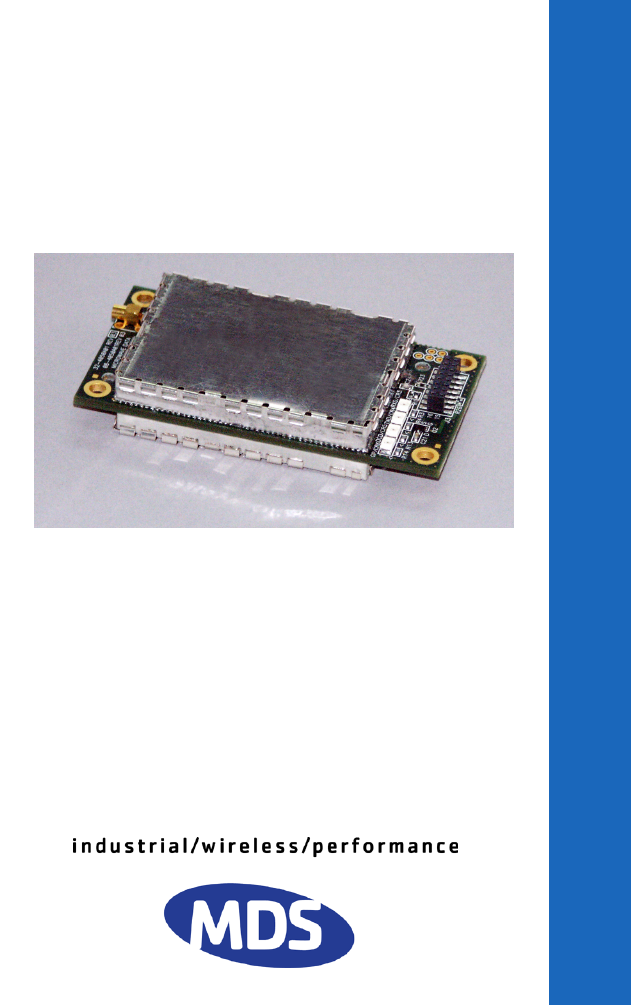
The OEM transceiver, (Figure 1), is a compact, spread spectrum wireless
module designed for license-free operation in the 2.4 GHz frequency range.
It is contained on one double-sided circuit board with all necessary
components and RF shielding included. It need only be protected from direct
exposure to the weather and is designed for rugged service in extreme
temperature environments. The transceiver has full over-the-air compatibility
with standard (non-OEM) TransNET
TM
transceivers manufactured by MDS.
All transceiver programming is performed via a connected PC terminal. No
jumper settings or manual adjustments are used to configure the transceiver
for operation.
Invisible place holder
Figure 1. TransNET OEM™ Transceiver
The transceiver employs Digital Signal Processing (DSP) technology for
highly reliable data communications, even in the presence of weak or
interfering signals. DSP techniques also make it possible to obtain
information about the radio’s operation and troubleshoot problems, often
eliminating the need for site visits.
Using appropriate software at the master station, diagnostic data can be
retrieved for any radio in the system, even while payload data is being
transmitted. (See “Network-Wide Remote Diagnostics” on Page 56.)

2 TransNET OEM 2.4 Integration Guide MDS 05-xxxxA01, Rev. 01
2.1 Transceiver Features
The OEM transceiver is designed for easy installation and flexibility in a wide
range of wireless applications. Listed below are several key features of the
transceiver which are described in more detail later in this guide.
• Three operating bands in the 2.4006 to 2.4820 GHz spectrum
• Configurable operating zones to omit frequencies with constant
interference
• 65,000 available network addresses to enhance communications
security
• Network-wide configuration from the master station; eliminates most
trips to remote sites
• Data transparency–ensures compatibility with virtually all
asynchronous data terminals
• Peak-hold RSSI, averaged over eight hop cycles
• Operation at up to 115,200 bps continuous data flow
• Store-and-Forward repeater operation
• Data latency typically less than 10 ms
• Same hardware for master or remote configuration
• Supports RS/EIA-232 or RS/EIA-485 interfaces (factory configured)
• Low current consumption—nominal 8 mA in “sleep” mode. Ideal for
solar/battery powered applications.
NOTE:
Some features may not be available on all units, based on the options pur-
chased and the regulatory constraints for the region in which the radio will op-
erate.
2.2 Model Configuration Codes
The model number code is printed on the radio module, and provides key
information about how it was configured when it left the factory. See Figure 2
for an explanation of the model number codes. (Note: This information is
subject to change and should not be used for ordering additional products.
Your factory representative can assist you with product ordering.)

MDS 05-xxxxA01, Rev. 01 TransNET OEM 2.4 Integration Guide 3
Figure 2. Model Number Configuration Codes
2.3 Spread Spectrum Transmission
The transceiver “hops” from channel to channel many times per second using
a specific hop pattern applied to all radios in the network. A distinct hopping
pattern is provided for each of the 65,000 available network addresses,
thereby minimizing the chance of interference with other spread spectrum
systems.
In the USA, and certain other countries, no license is required to install and
operate this type of radio device, provided RF power and antenna gain
restrictions are observed. In the USA and Canada, a maximum of 36 dBm
Effective Isotropic Radiated Power (EIRP) is allowed. The factory offers a set
of approved antennas with special connectors for this radio. Substitutions that
would void the compliance of the device are not permitted.
2.4 Typical Applications
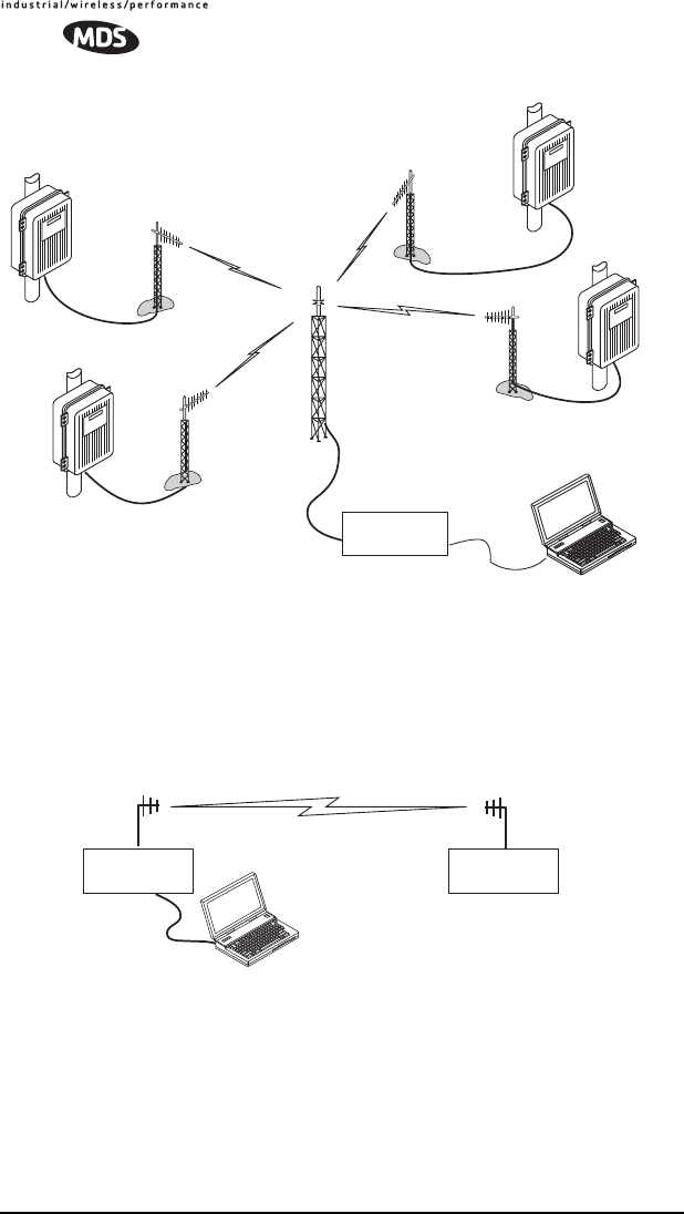
Multiple Address Systems (MAS)
This is the most common application of the transceiver. It consists of a central
control station (master) and two or more associated remote units, as shown in
Figure 3. This type of network provides communications between a central
host computer and remote terminal units (RTUs) or other data collection
devices. The operation of the radio system is transparent to the computer
equipment. This application provides a practical alternative to traditional
(licensed) MAS radio systems.
BAND
(2) 2.4 GHz
ENCLOSURE
(0) Modular-no enclosure
AGENCY
(N) None
(F) FCC/IC
SAFETY CERT.
(N) N/A
RESERVED
(N) None
OPERATION
(X) Remote/Master
ELxxx.x
INTERFACE SIGNALING & INPUT POWER OPTIONS
(0) Payload RS-232/485; Diagnostics RS-232; DC Input +3.3 Vdc
(1) Payload TTL; Diagnostic RS-232; DC Input +3.3 Vdc
(2) Payload TTL; Diagnostic TTL; DC Input 3.3 Vdc
(3) Payload RS-232/485; Diagnostic RS-232; DC Input +6-18 Vdc
(4) Payload TTL; Diagnostic RS-232; Input +6-18 Vdc
(5) Payload TTL, Diagnostic TTL; DC Input +6-18 Vdc
RESERVED
(N) None
DIAGNOSTICS
(N) None
(W) Network-wide
SPARE
(N) None
02N
0
0X
INTERFACE MODE
(0) EIA/RS-232
(1) EIA/RS-485
(2) TTL
W
4 TransNET OEM 2.4 Integration Guide MDS 05-xxxxA01, Rev. 01
Invisible place holder
Figure 3. Typical MAS Network
Point-to-Point System
A point-to-point configuration (Figure 4) is a simple arrangement consisting
of just two radios—a master and a remote. This provides a half-duplex
communications link for the transfer of data between two locations.
Invisible place holder
Figure 4. Typical Point-to-Point Link
MASTER SITE
DATA
TRANSCEIVER
RTU/PLC WITH
TRANSCEIVER
INSTALLED
RTU/PLC WITH
TRANSCEIVER
INSTALLED
RTU/PLC WITH
TRANSCEIVER
INSTALLED
RTU/PLC WITH
TRANSCEIVER
INSTALLED
Master Site Remote Site
Host System
DATA
TRANSCEIVER DATA
TRANSCEIVER
MDS 05-xxxxA01, Rev. 01 TransNET OEM 2.4 Integration Guide 5
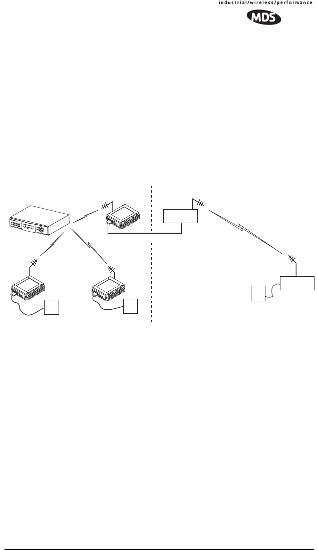
Tail-End Link to an Existing Network
A tail-end link is often used to extend the range of a traditional (licensed)
MAS system without adding another licensed radio. This might be required
if an outlying site is blocked from the MAS master station by a natural or
man-made obstruction. In this arrangement, a spread spectrum transceiver
links the outlying remote site into the rest of the system by sending data from
that site to an associated transceiver installed at one of the licensed remote
sites—usually the one closest to the outlying facility. (See Figure 5).
As the data from the outlying site is received at the associated transceiver, it
is transferred to the co-located licensed radio (via a data crossover cable) and
is transmitted to the MAS master station over the licensed channel.
Additional details for tail-end links are given in Section 7.2 (Page 25).
Invisible place holder
Figure 5. Typical Tail-End Link Arrangement
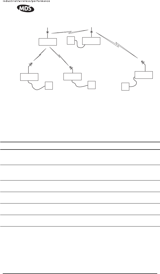
Store-and-Forward Repeater
Similar to a Tail-End Link, Store-and-Forward (SAF) offers a way to
physically extend the range of a network, but in a simplified and economical
manner. SAF operates by storing up the data received from one site, and then
retransmitting it a short time later. Figure 6 shows a typical SAF repeater
arrangement.
SAF operates by dividing a network into a vertical hierarchy of two or more
sub-networks. Extension radios (designated as
MODE X
) serve as single-radio
repeaters that link adjacent sub-networks, and move data from one
sub-network to the next. Additional information on SAF mode is provided in
“Store & Forward (SAF) Operation with Extension Radios” on Page 26.
REPEATER STATION
Remote Radio
ENTER
ESCAPE
ACTIVE
ACTIVE
STBYALARMRX ALRTX ALR
STBYALARMRX ALRTX ALRLINE
LINE
Null-Modem Cable
Remote
Radio
Remote
Radio
Master Station
SPREAD SPECTRUM LINK
TO OUTLYING SITE
OUTLYING
REMOTE SITE
MAS SYSTEM (LICENSED OR UNLICENSED) LICENSE-FREE SPREAD SPECTRUM SYSTEM
RTU RTU
RTU
DATA
TRANSCEIVER
DATA
TRANSCEIVER
6 TransNET OEM 2.4 Integration Guide MDS 05-xxxxA01, Rev. 01
Invisible place holder
Figure 6. Store-and-Forward Repeater Network
2.5 Transceiver Accessories
One or more of the accessories listed in Table 1 may be used with the OEM
transceiver. Contact your factory representative for availability and ordering
details.
Table 1. OEM Transceiver Accessories
Accessory Description Part No.
AC Power Adapter Small power supply designed for continuous
operation of the transceiver. UL approved. In-
put: 120/220; Output: 12 Vdc.
01-3862A02
TransNET Support
Package CD Programming, diagnostic and support files on a
CD ROM. Includes electronic copy of this guide
(PDF format).
03-2708A01
RJ-11-to-DB9
Adapter Cable Short cable assembly that converts RJ-11 to
DB9 connector type 03-3246A01
Fuse (for Evalua-
tion Board) 2A SMF Slo-Blo (plugs into FH1 on Evaluation
Board) 29-1784A03
InSite Diagnostic
Software PC-based diagnostic software for MDS radios.
Supplied on CD. 03-3533A01
Omnidirectional
Antennas Rugged antennas suitable for use at Master
stations. Various
Programmed as
MODE X
STORE & FORWARD REPEATER STATION
SPREAD SPECTRUM LINK
TO OUTLYING SITE
OUTLYING
REMOTE SITE
Programmed as
MODE M
Programmed as
MODE R
Programmed as
MODE R
Programmed as
MODE R
RTU RTU RTU
RTU
DATA
TRANSCEIVER
DATA
TRANSCEIVER
DATA
TRANSCEIVER
DATA
TRANSCEIVER DATA
TRANSCEIVER

MDS 05-xxxxA01, Rev. 01 TransNET OEM 2.4 Integration Guide 7
3.0 BENCHTOP SETUP & EVALUATION
As an Integrator, your first task is to verify that the OEM module will function
as intended with the host equipment. This section describes how to test the
unit for operation with host devices such as RTUs, PLCs and similar gear. It
covers the steps for making interface connections, powering up the
transceiver, and setting configuration parameters using a connected PC.
Evaluation of the module is best performed in a controlled environment, such
as a shop or lab facility where you can readily test various hardware and
programming configurations and observe the effects of these changes before
final installation.
Once you are satisfied that the transceiver module operates properly on the
bench, you can plan the installation of the module inside the host device and
be assured of proper operation in the field.
3.1 Evaluation Development Kit
The Evaluation Development Kit is designed to assist integrators who will be
working with the transceiver in a benchtop setting. The kit contains the
following:
• Two OEM Transceiver modules (configured for TTL, or RS-232/485
operation, as requested)
• Two Evaluation Development boards (P/N 03-4051A01)
• Interface Cables
• Two whip antennas
• Two 12 Vdc power supplies
• TransNET Support CD containing software for programming &
diagnostics
Yagi Antenna Rugged directional antennas suitable for use at
Remote stations. Various
Whip Antennas Short, flexible antennas suitable for
short-range applications. Available with and
without coaxial feedlines.
Various
Bandpass Filter Antenna system filter to aid in eliminating inter-
ference from high power transmitters, such as
those used in paging systems.
20-2822A01
Evaluation
Development Kit Kit containing two OEM Transceiver modules,
whip antennas, two Evaluation Boards, support
software on CD, cables, power supplies and
other accessories needed to operate the trans-
ceiver in a benchtop setting.
Consult
Factory
Table 1. OEM Transceiver Accessories
(Continued)