GE MDS DS-EL806-24 2.4 GHz TransNet User Manual xxxxA TNET2 4 OEM Body
GE MDS LLC 2.4 GHz TransNet xxxxA TNET2 4 OEM Body
GE MDS >
Contents
- 1. Users Manual Part 1
- 2. Users Manual Part 2
- 3. Users Manual Part 3
- 4. Users Manual Part 4
Users Manual Part 3
18 TransNET OEM 2.4 Integration Guide MDS 05-xxxxA01, Rev. 01
4.0 EVALUATION BOARD DOCUMENTATION
This section contains an assembly drawing and parts list for the OEM
Evaluation Board. In addition, a separate foldout schematic of the Board is
included at the back of this manual. Board documentation is provided to assist
integrators who need to create compatible interface circuitry between the
OEM transceiver and host equipment.
NOTE: The foldout schematic may also be accessed from the TransNET Support
Package CD, or from our website at: www.microwavedata.com.
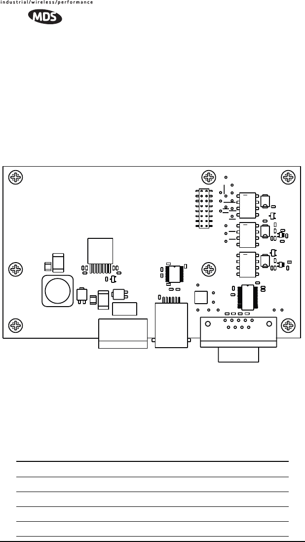
4.1 Assembly Drawing
Invisible place holder
Figure 14. Evaluation Board Assembly Diagram
4.2 Parts List
Table 6 lists the electronic components used on the Evaluation Board.
Table 6. OEM Evaluation Board Parts List
Ref. Desig. Part Description
CR1 DIODE, SOT23 SMALL SIG 914 5D
CR4 CR5 CR6 RECTIFIER, 30V B13
CR2 CR3 DIODE, SCHOTTKY POWER, SMT, SNGL, UPS840
Q1 Q2 TRANSISTOR, SOT23 NPN 6429 M1LR
C8
R10
R3
C26
R9
C9
C4
C1
C20
C18
C19
R5
TXD
GND
R11
NA
A
C
CR1
R7
C23
C24
C10
C7
+
C30
R4
R8
CTS
REG_PWR
C13
ALARM
C29
C11
C2
C5
C3
o
28
U1
C31 C6
16
J4
CR2
C16
1
5U4
51U5
R6
R12
RTS K2
<
CR4
<
CR5
R15
C21
C17
R13
C14
+
C12
DIAG_RXD
DIAG_TXD
GND
SLEEP
CR3
FH1
B
E
C
Q1
B
EQ2
C
R14
C15
C22 C25
RXD
UNREG_PWR
K3
K1
SHUTDN
DCD
LED
<
CR6
o
U3
o
1
U2
16 15
21
J2
21
J1
9
51
6
J5
L1
1
J3

MDS 05-xxxxA01, Rev. 01 TransNET OEM 2.4 Integration Guide 19
U4 U5 IC, LINEAR SC70-5 COMPARATOR SNGLE LMV33
U1 IC, IN'FACE SSOP28 RS-232 TXVR SP3238E
U3 IC, IN'FCE 20PIN TSSOP DRIVER SP3222
U2 IC, SWITCHING REG'R ADJ.4.5A LT1374HVIR
K1 K2 K3 RELAY, DPDT
R10 RESISTOR, CHIP 0603 1/16W 5% 2.2K
R4 R5 R13 R14 RESISTOR, CHIP 0603 1/10W 1% 10K
R12 RESISTOR, CHIP O603 1/10W 1% 100K
R7 R9 RESISTOR, CHIP 0603 1/10W 1% 1.5K
R11 RESISTOR, CHIP O603 1/10W 1% 1.82K
R3 RESISTOR, CHIP 0603 1/10W 1% 22.6K
R15 RESISTOR, CHIP O603 1/10W 1% 31.6K
R8 RESISTOR, CHIP 0603 1/10W 1% 470 OHM
R6 RESISTOR, CHIP O603 1/10W 1% 6.81K
C12 CAP, TANT 7343 20% 10V 100uf
C6 C7 C9 C10
C11 C29 C31 CAP, CHIP 0603 50V NPO 5% 100pf
C1 C2 C3 C4 C5
C17 C18 C19
C20 C21 C22
C23 C24 C25
C26 C8
CAP, CHIP 0603 X7R 10% 0.1uF
C13 CAP, CHIP 0603 X7R 10% 470 pf
C14 CAP, CHIP 0603 X7R 10% 4700pF
C15 Capacitor, Low ESR Chip Ceramic, 1210 22uF
C16 Capacitor, Low ESR Chip Ceramic, 1210 4.7
L1 INDUCTOR, SWITCHING, 20%, 10uH
J1 CONN, HEADER, .100 DUAL STR 4-PIN
P/O J1 1-2, P/O
J1 3-4
CONN, JUMPER
FH1 FUSE HOLDER, PCB SMT W/2A SLO-BLO FUSE
Table 6. OEM Evaluation Board Parts List (Continued)

20 TransNET OEM 2.4 Integration Guide MDS 05-xxxxA01, Rev. 01
4.3 Evaluation Board Fuse Replacement
The Evaluation Board is protected by a 2 ampere fuse. The fuse can be blown
by an over-current condition caused by an internal failure or over-voltage.
Follow the procedure below to remove and replace the fuse:
1. Disconnect the primary power cable and all other connections to the
Evaluation Board.
2. Locate the fuse holder assembly, FH1, behind the green power connector,
J3.
3. Loosen the fuse from the holder using a very small screwdriver, then use
a small pair of needle-nose pliers to pull the fuse straight up and out of
the holder.
4. Use an ohmmeter or other continuity tester to verify that the fuse is open.
5. Install a new fuse in the holder. Replacement fuse information: Littelfuse
#0454002; 452 Series, 2 Amp SMF Slo-Blo fuse (MDS Part No.
29-1784A03).
J2 CONN, HEADER, PC MOUNT .078, DUAL, 16 PIN
Samtec TW Series, Part No: ASP 103812-01
(Mates with J3 on the OEM radio transceiver)
J3 CONN, TERM STRIP, 5MM PCB
J4 CONN, TELE JACK 6POS 6CON RT A SMT W/F
J5 CONN, D-SUB, PCB RCPT 90 DEGREE, 9 PIN
Table 6. OEM Evaluation Board Parts List (Continued)
MDS 05-xxxxA01, Rev. 01 TransNET OEM 2.4 Integration Guide 21
5.0 TRANSCEIVER MOUNTING
This section provides information for mounting the OEM transceiver in a host
device. The module need only be protected from direct exposure to the
weather. No additional RF shielding is required.
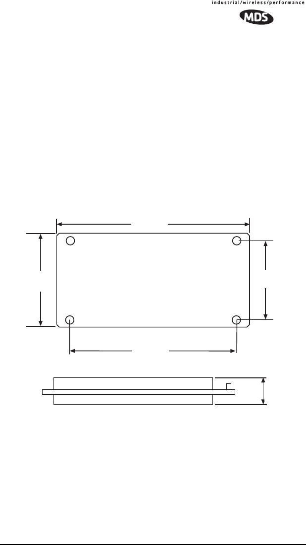
5.1 Mounting Dimensions
Figure 15 shows the dimensions of the transceiver board and its mounting
holes. If possible, choose a mounting location that provides an unobstructed
view of the radio’s LED status indicators when viewing the board from
outside the host device.
Mount the transceiver module to a stable surface using the four mounting
holes at the corners of the PC board. Standoff spacers should be used to
maintain adequate clearance between the bottom of the circuit board and the
mounting surface. (Fasteners/anchors are not normally supplied.)
Figure 15. Transceiver Mounting Dimensions
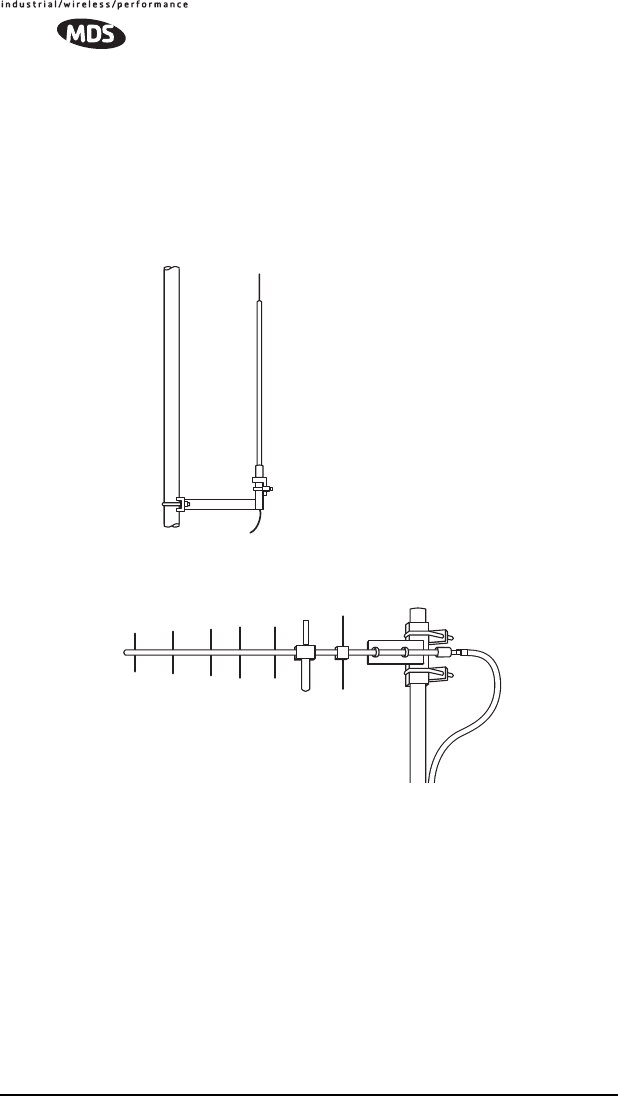
5.2 Antennas & Feedlines
A number of omnidirectional and directional antennas are available for use
with the radio. Contact your factory representative for specific
recommendations on antenna types and hardware sources. In general, an
omnidirectional antenna (Figure 16) is used at master station sites in order to
provide equal coverage to all of the remote units.
3.11”
(7.9 cm)
1.49˝
(3.8 cm)
0.63”
(16 mm)
1.81˝
(46 mm)
3.45”
(87.5 mm)
Top View
Side View
22 TransNET OEM 2.4 Integration Guide MDS 05-xxxxA01, Rev. 01
At remote sites and in many point-to-point systems, a directional Yagi
antenna (Figure 17) is generally recommended to minimize interference to
and from other users and to maximize range.
For systems operating in a very short range environment, small, flexible whip
antennas may also be supplied. Such antennas are available for direct
connection to the transceiver module, or for exterior mounting with various
lengths of feedline.
Invisible place holder
Figure 17. Typical Yagi Antenna (shown mounted to mast)
Feedlines
The feedline supplied with the antenna was carefully selected to minimize RF
loss and ensure regulatory compliance with the antenna being used. Do not
make substitutions or change the lengths of the antenna system feedline. If
you require a different length of feedline for your installation, contact your
factory representative for assistance.
NOTE: Strong fields near the antenna can interfere with the operation of the low level
RTU circuits and change the reported values of the data being monitored. If in-
terference is experienced, it may be necessary to re-orient the antenna with re-
spect to the radio, RTU, sensors or other components of the system.
Figure 16.
Omnidirectional Antenna
(shown mounted to mast)

MDS 05-xxxxA01, Rev. 01 TransNET OEM 2.4 Integration Guide 23
6.0 EIRP Compliance Check
IMPORTANT: To comply with FCC and Industry Canada rules, the effective
isotropic radiated power (EIRP) of an OEM transceiver installation must not
exceed 36 dBm.
Transceiver modules are shipped from the factory with an RF output setting
of +27 dBm. This setting is password-controlled and may not be changed by
unauthorized persons. This power level provides EIRP compliance when the
module is used with many types of antennas, however, each installation must
be carefully evaluated to ensure compliance. The formula for determining
EIRP is as follows:
Transmitter RF output power (dBm) + Antenna gain (dBi) – Feedline loss (dB)
Table 7 shows three types of antennas and their associated gains. Note that for
a 10 dBi gain antenna, the system must include at least 1 dB of feedline loss
to achieve EIRP compliance. Higher gain antennas would require additional
feedline loss in order to limit the EIRP to a maximum of 36 dBm.
If no feedline is used (directly connected antenna), with an antenna gain
exceeding 9 dBi, it will be necessary to reduce the transmitter output power
to less than +27 dBm. Contact MDS for further information. In no case shall
the station’s EIRP exceed 36 dBm.
7.0 OPTIMIZING PERFORMANCE
After the basic operation of the radio has been checked, you may wish to
optimize its performance using some of the suggestions given here. The
effectiveness of these techniques will vary with the design of your system and
the format of the data being sent.
Complete instructions for using the commands referenced in this manual are
provided in “PROGRAMMING REFERENCE” on Page 34.
Table 7. Antenna System Gain vs. EIRP
Antenna Type
(Model No.) Gain
(dBi)
Transmitter
Power Setting
(dBm)
EIRP
(dBm)
1/2 Wave Whip Dipole
(MHWS2400MSMA) 2 +27 29
Omni-directional Base Station
(MFB24010) 10* +27 37*
Yagi Directional (MYP24010PT) 10* +27 37*
* These antenna systems must include a feedline loss of at least 1 dB to maintain
compliance with the EIRP limit of 36 dBm.

24 TransNET OEM 2.4 Integration Guide MDS 05-xxxxA01, Rev. 01
7.1 Antenna Aiming
For optimum performance of directional antennas (yagis), they must be
accurately aimed in the direction of desired transmission. The easiest way to
do this is to point the antenna in the approximate direction, then use the
remote radio’s RSSI command (Received Signal Strength Indicator) to further
refine the heading for maximum received signal strength.
In an MAS system, RSSI readings are only meaningful when initiated from a
remote station. This is because the master station typically receives signals
from several remote sites, and the RSSI would be continually changing as the
master receives from each remote in turn.
7.2 Antenna SWR Check
It is necessary to briefly key the transmitter for this check by placing the radio
in the SETUP mode (Page 49) and using the KEY command. (To unkey the
radio, enter DKEY; to disable the SETUP mode and return the radio to normal
operation, enter Q or QUIT.)
The SWR of the antenna system should be checked before the radio is put into
regular service. For accurate readings, a wattmeter suited for 2.4 GHz is
required. One unit meeting this criteria is the Bird Model 43 directional
wattmeter with an appropriate element installed.
The reflected power should be less than 10% of the forward power (≈2:1
SWR). Higher readings usually indicate problems with the antenna, feedline
or coaxial connectors.
7.3 Data Buffer Setting
The default setting for the data buffer is OFF. This allows the radio to operate
with the lowest possible latency and improves channel efficiency. MODBUS
and its derivatives are the only protocols that should require the buffer to be
turned on. See “BUFF [ON, OFF]” on Page 42 for details.
7.4 Hoptime Setting
The default hop-time setting is 7 (7 ms). An alternate setting of 28 is used to
increase throughput, but at the cost of increased latency. A detailed
explanation of the HOPTIME command can be found on Page 44.
7.5 Operation at 115200 bps
Burst throughput at 115200 bps is supported at all settings. The radio will
always buffer at least 500 characters. Sustained throughput at 115200bps is
only possible when the data path is nearly error free and the operating settings
have been properly selected. For sustained operation at 115200 bps, use the
following settings: SAF OFF, FEC OFF, REPEAT 0, RETRY 0, HOPTIME 28.

MDS 05-xxxxA01, Rev. 01 TransNET OEM 2.4 Integration Guide 25
7.6 Baud Rate Setting
The default baud rate setting is 19200 bps to accommodate most systems. If
your system will use a different data rate, you should change the radio’s data
interface speed using the BAUD xxxxx abc command (Page 42). It should be
set to the highest speed that can be sent by the data equipment in the system.
(The transceiver supports 1200 to 115200 bps.)
7.7 Radio Interference Checks
The radio operates in eight frequency zones. If interference is found in one or
more of these zones, the SKIP command (Page 49) can be used to omit them
from the hop pattern. You should also review 8.0 DEALING WITH
INTERFERENCE, when interference problems are encountered.
8.0 OPERATING PRINCIPLES & SPECIAL
CONFIGURATIONS
8.1 How Remotes Acquire Synchronization
Remotes acquire synchronization and configuration information via SYNC
messages sent from the Master (the MODE M unit) or from any valid
Extension (MODE X unit).
The Master will always transmit SYNC messages. An Extension will only
start sending SYNC messages after synchronization is achieved with its
Master.
The ability to synchronize to a given radio is further qualified by the sender’s
Extended Address (XADDR) and by receiver’s Synchronization Qualifiers
(XMAP, XPRI, and XRSSI).
When a primary is specified (XPRI is 0...31), a radio will always attempt to
find the primary first. If 30 seconds elapses and the primary is not found, then
the radio will attempt to synchronize with any non-primary radio in the XMAP
list.
Once every 30 minutes, if a primary is defined, the radio will check its
synchronization source. If the radio is synchronized to a unit other than the
primary, then the current RSSI value is compared to the XRSSI value. If RSSI
is less than XRSSI (or if XRSSI is NONE) the radio will force a
loss-of-synchronization, and hunt for the primary again (as described in the
previous paragraph).
By default, Extensions (and the Master) begin with XADDR 0.
Synchronization qualifiers are set to XMAP 0, XPRI 0, and XRSSI NONE,
respectively. This default configuration allows any radio to hear the Master.
When an Extension is added, the extended address of the Extension must be
set to a unique value. All remotes that need to hear that extension can specify
this either by designating the extension as the primary (XPRI), or by including
it in their list of valid synchronization sources (XMAP).
26 TransNET OEM 2.4 Integration Guide MDS 05-xxxxA01, Rev. 01
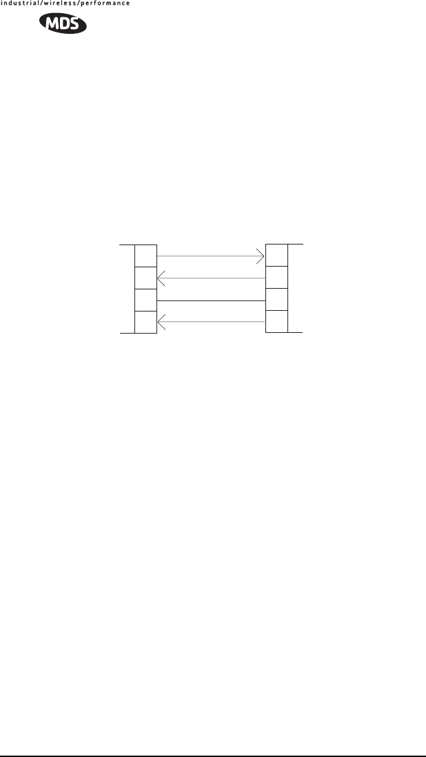
8.2 Establishing a Tail-End Link
A tail-end link can be used to bring an outlying remote site into the rest of an
MAS network. Figure 5 on Page 5 shows a diagram of this type of system.
A tail-end link is established by connecting an OEM transceiver
“back-to-back” with another unit such as a licensed MDS x710 Series
transceiver. The wiring connections between the two radios must be made as
shown in Figure 18. In addition, the DEVICE CTS KEY command must be
asserted at the OEM radio.
Figure 18. Data Crossover Cable for Tail-End Links
8.3 Store & Forward (SAF) Operation with Extension
Radios
The Store-and-Forward (SAF) capability allows individual radios to act as
data repeaters. SAF operates by dividing a network into a vertical hierarchy
of two or more sub-networks. (See Figure 6 on Page 6.) Adjacent
sub-networks are connected via Extension radios operating in “MODE X”
which move data from one sub-network to the next one.
The Store-and-Forward implementation adheres to the general polling
principles used in most multiple-address systems (MAS). Polls originate from
the Master station, broadcast to all radios within the network, and travel
hierarchically downward. All Remotes will hear the same message, but only
one Remote will respond. Messages within a hierarchy only travel in one
direction at a time.
Using SAF will cut the overall data throughput in half, however, multiple
networks can be inter-connected with no additional loss in network
throughput.
If required.
RXD
TXD
GND
RTS
3
2
7
4
DCE
DB-25
MDS x710 Series
Remote Transceiver
(or device requiring keyline)
TXD
RXD
GND
CTS
10
14
5
DCE
16-pin header (J3)
TransNET OEM
Remote Transceiver
(DEVICE CTS KEY)
16
MDS 05-xxxxA01, Rev. 01 TransNET OEM 2.4 Integration Guide 27
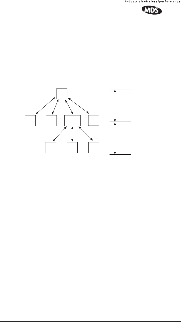
Simple Extended SAF Network
Figure 19 depicts a two-level network utilizing a single Master (M) and an
Extension (X) radio. In this network, messages directed to Remotes in the
“K” sub-network, will be relayed through Extension radio Xj,k to the
K-Remotes. Any response from a Remote in sub-network “K” will pass back
through Extension radio Xj,k to the Master Mj. Radios in sub-network “J”
operate on the same set of frequencies and sub-network “K” but with a
different radio-frequency hopping pattern.
Invisible place holder
Figure 19. Simple Extended SAF Network
Networks: J and K
In the SAF operation, the Extension radios are set to MODE X
(Details page 45) and operate with a “dual personality”—50% of the time
they serve as a Remote station and 50% of the time as a Master for
sub-network Remotes.
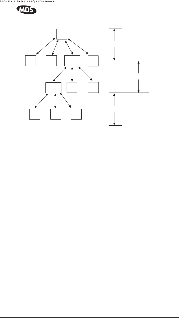
Extended SAF Network
Below is an example of a multilevel network utilizing two repeaters—XJ,K
and XK,L. The example demonstrates the extensibility of the network. In this
case, messages directed to Remotes in the sub-network L will be relayed
through Extension radios XJ,K and XK,L. As in the previous example, the
Extension radios will split their operating time equally between their Master
and Remote personalities. This multi-layered network can be extended
indefinitely without degrading system throughput beyond that initially
incurred by placing the network in the SAF mode.
MJ
RJ
RJXJ,K
RJ
RKRRKK
Sub-Network J
Sub-Network K
28 TransNET OEM 2.4 Integration Guide MDS 05-xxxxA01, Rev. 01
Invisible place holder
Figure 20. Extended SAF Network
Networks: J, K, L
Retransmission and ARQ operation
Functionally, the sub-network side of an Extension behaves like a
corresponding connection between a master and a remote.
When an Extension is using its “master personality” it sends
acknowledgments and performs unconditional retransmissions based on its
REPEAT count.
When an Extension is using its “Remote personality”, acknowledgments are
processed and retransmissions occur as needed, up to the number of times
specified by the RETRY count value.
If new data arrives—from a new source—prior to completion of
retransmissions, then this is considered a violation of the polling model
protocol. The new data takes precedence over the old data and the old data is
lost. In such a situation, new data is likely to be corrupt as it will have some
old data mixed in with it.
Synchronization in SAF Networks
The Master controls the synchronization for a given network for all modes.
Setting the Master to “SAF ON” broadcasts a command from the Master to all
radio units in the associated network either directly or through an Extension
radio. This command puts all radios in the entire system in a special
time-division duplexing mode that alternates between two timeslots. One
time slot for data communications upstream and another for downstream
communications.
XK,L
RL
RL
MJ
RJ
RJXJ,K
RJ
RKRK
RL
Sub-Network J
Sub-Network K
Sub-Network L

MDS 05-xxxxA01, Rev. 01 TransNET OEM 2.4 Integration Guide 29
The Extensions are single radios which serve as bridges between adjacent
sub-network levels. Extensions will undertake a “remote” personality in one
timeslot, and a “master” personality in the alternate timeslot and provide
communications with associated Remotes downstream. Extensions behave
like two radios with their data ports tied together, first synchronizing with
their upstream Master during their Remote personality period, and then
providing synchronization signals to dependent Remotes downstream during
its Master personality period.
All Remotes synchronize to a corresponding Master. This can be the “real
master” (the MODE M unit), or it can be a repeater “Extension” that derives
synchronization from the “real master.”
Payload polls/packets broadcast from the network Master will be repeated to
all levels of the network, either directly to Remotes, or through network
repeaters—the Extensions station. The targeted Remote will respond to the
poll following the same path back to the Master.
Configuration Parameters for Store-and Forward Services
The installation and configuration of a network with an Extension using SAF
is straight-forward with only a few unique parameters that need to be
considered and set at each unit.
In every network there can be only one Master station. It will serve as the sole
gateway to the outside world. The following three tables detail the parameters
that will need to be set on each type of radio in the network.
• Network Master Radio—Table 8 on Page 29
• Extension Radio(s)—Table 9 on Page 30
• Remote Radio(s)—Table 10 on Page 31
Table 8. Configuration Parameters for SAF Services
Network Master Radio
Parameter Command Description
Operating Mode MODE M
Details page 45 Set the radio to serve as a
Master
Network Address ADDR
Details page 40 A number between 1 and
65,000 that will serve as a
common network ad-
dress.
All radios in the network
use the same number.

30 TransNET OEM 2.4 Integration Guide MDS 05-xxxxA01, Rev. 01
Extended Address XADDR
Details page 51 A number between 0 and
31 that will serve as a
common address for radi-
os that synchronize di-
rectly to this master.
Typically, the Master is
set to zero (0).
Store and Forward
Mode SAF ON
Details page 49 Enables store and for-
ward capability in the net-
work.
Table 9. Configuration Parameters for SAF Services
Extension Radio(s)
Parameter Command Description
Operating Mode MODE X
Details page 45 Set the radio to serve as an
Extension
Network Address ADDR
Details page 40 A number between 1 and
65,000 that will serve as a
common network address.
All radios in the network use
the same number.
Extended Ad-
dress XADDR
Details page 51 A number between 0 and 31
that will serve as a common
address for radios that syn-
chronize directly to this Ex-
tension radio serving as
master for associated
sub-network units.
We recommend using zero
(0) for the Master station.
Primary Extended
Address XPRI
Details page 51 XADDR number of the pri-
mary or preferred radio with
which this radio will synchro-
nize.
Extension Map XMAP
Details page 51 Functional list of all XADDR
values with which this radio
can synchronize, excluding
the XPRI address
Extension
Received Signal
Strength Indicator
XRSSI
Details page 51 The minimum RSSI level re-
quired to preserve synchro-
nization with a non-primary
radio. (Ineffective when
XPRI is NONE)
Table 8. Configuration Parameters for SAF Services
Network Master Radio (Continued)
Parameter Command Description

MDS 05-xxxxA01, Rev. 01 TransNET OEM 2.4 Integration Guide 31
8.4 Sleep Mode Operation (Remote units only)
In some installations, such as at solar-powered sites, it may be necessary to
keep the transceiver’s power consumption to an absolute minimum. This can
be accomplished using the radio’s Sleep Mode feature. In this mode, power
consumption is reduced to about 8 mA.
Sleep Mode can be enabled under RTU control by asserting a ground (on Pin
6 of J3, the radio’s header connector. The radio stays in Sleep Mode until the
low is removed, and all normal functions are suspended.
The radio can be “awakened” by your RTU every minute or so to verify
synchronization with the master station. When the ground is removed, the
radio will be ready to receive data within 75 milliseconds.
NOTE: The SLEEP function must be set to ON; otherwise a ground on the Sleep Mode
pin will be ignored.
Table 10. Configuration Parameters for SAF Services
Remote Radio(s)
Parameter Command Description
Operating Mode MODE R
Details page 45 Set the radio to serve
as a Remote station
Network Address ADDR
Details page 40 A number between 1
and 65,000 that will
serve as a common
network address or
name.
Same number for all
units in the same net-
work.
Primary Extended
Address XPRI
Details page 51 XADDR number of the
primary or preferred
radio with which this
radio will synchronize.
Extension Map XMAP
Details page 51 A list of all XADDR val-
ues with which this ra-
dio can synchronize,
excluding the XPRI
address
Extension
Received Signal
Strength Indicator
XRSSI
Details page 51 The minimum RSSI
level required to pre-
serve synchronization
with a non-primary ra-
dio. (Ineffective when
XPRI is NONE)

32 TransNET OEM 2.4 Integration Guide MDS 05-xxxxA01, Rev. 01
It is important to note that power consumption will increase somewhat as
communication from the master station degrades. This is because the radio
will spend a greater period of time “awake” looking for synchronization
messages from the master radio.
In order for the radio to be controlled by the Sleep Mode pin, the radio must
be set to SLEEP ON. See “SLEEP [ON, OFF]” on Page 50 for more
information.
Sleep Mode Example
The following example describes Sleep Mode implementation in a typical
system. Using this information, you should be able to configure a system that
meets your own particular needs.
Suppose you need communications to each remote site only once per hour.
Program the RTU to raise an EIA/RS-232 line once each hour (DTR for
example) and wait for a poll and response before lowering it again. Connect
this line to Pin 6 of the radio’s header connector. This will allow each RTU
to be polled once per hour, with a significant savings in power consumption.
9.0 DEALING WITH INTERFERENCE
The transceiver shares the frequency spectrum with other services and other
Part 15 (unlicensed) devices in the USA. As such, near 100% error free
communications may not be achieved in a given location, and some level of
interference should be expected. However, the radio’s flexible design and
hopping techniques should allow adequate performance as long as care is
taken in choosing a suitable location and in configuring the radio’s operating
parameters.
In general, keep the following points in mind when setting up your
communications network:
1. Systems installed in rural areas are least likely to encounter interference;
those in suburban and urban environments are more likely to be affected
by other devices operating in the license-free frequency band and by
adjacent licensed services.
2. If possible, use a directional antenna at remote sites. They confine the
transmission and reception pattern to a narrow lobe, which minimizes
interference to (and from) stations located outside the pattern.
3. If interference is suspected from a nearby licensed system (such as a
paging transmitter), it may be helpful to use horizontal polarization of all
antennas in the network. Because most other services typically use
vertical polarization in this band, an additional 20 dB of attenuation to
interference can be achieved by using the horizontal plane.
4. Multiple spread spectrum systems can co-exist in close proximity to each
other with only minor interference, provided they are each assigned a
unique network address. Each network address has a different hop pattern
associated with it.