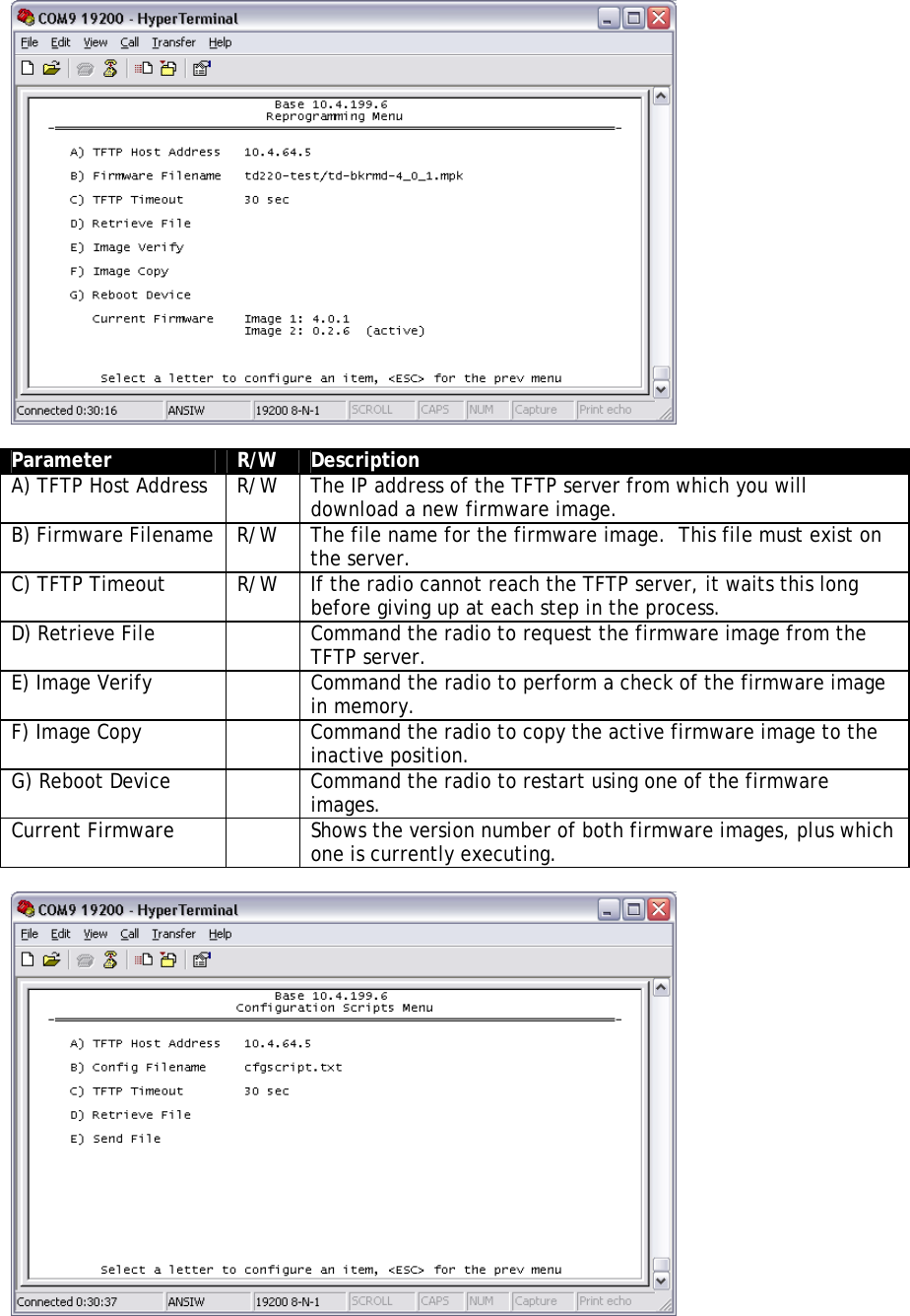
GE MDS DS-TD220 Narrowband Wireless Transceiver User Manual Login with user name admin password admin

GE MDS LLC Narrowband Wireless Transceiver Login with user name admin password admin

Contents

User Manual

 TD220 Manual Preliminary Version 1
Table of Contents  1 Important Information............................................................................................................ 3 1.1 Antenna Installation Warnings........................................................................................ 3 1.2 ESD Notice ..................................................................................................................... 3 1.3 FCC Approval Notice...................................................................................................... 3 1.4 FCC Part 15 Notice ........................................................................................................ 3 1.5 Industry Canada RSS-119 (Pending)............................................................................. 3 2 Introduction ........................................................................................................................... 4 3 Interfaces .............................................................................................................................. 5 3.1 Data Interface (DB-25) ................................................................................................... 5 3.2 USB ................................................................................................................................6 3.3 Power.............................................................................................................................. 6 3.4 Antenna Connector......................................................................................................... 6 4 Common Setup Tasks........................................................................................................... 7 4.1 Key the Transmitter for Test Purposes........................................................................... 7 4.2 Prepare the Network Interface for a Radio..................................................................... 7 4.3 Set Up a Base Unit......................................................................................................... 7 4.4 Set Up a Mobile Unit....................................................................................................... 7 4.5 Perform Test Polling....................................................................................................... 8 5 Menu Interface ...................................................................................................................... 14 5.1 Main Menu...................................................................................................................... 15 5.2 Network Configuration Menus........................................................................................ 16 5.3 System Configuration Menus ......................................................................................... 17 5.4 Radio Configuration Menu.............................................................................................. 19 5.5 Security Configuration Menu .......................................................................................... 20 5.6 Statistics/Logging Menus................................................................................................ 20 5.7 Device Information Menus.............................................................................................. 24 5.8 Maintenance/Tools Menus ............................................................................................. 25 6 Troubleshooting .................................................................................................................... 27
1  Important Information 1.1 Antenna Installation Warnings 1.  All antenna installation and servicing is to be performed by qualified technical personnel only. When servicing the antenna, or working at distances closer than those listed below, ensure the transmitter has been disabled. 2.  Depending upon the application and the gain of the antenna, the total composite power could exceed 90 watts EIRP. For fixed/mobile configuration, the distances in the table below must be followed.  Antenna Gain vs. Minimum Safety Distance (Based upon a 50% Duty Cycle, 0 dB Feedline Loss) Uncontrolled Exposure limits    Fixed/Mobile Antenna Gain 0-6 dBi  6-10 dBi  10-16.5 dBi Minimum RF Safety Distance  1.50 meters  2.37 meters  5.01 meters 1.2 ESD Notice To prevent malfunction or damage to this product, which may be caused by Electrostatic Discharge (ESD), the radio should be properly grounded at the time of installation. In addition, the installer or maintainer should follow proper ESD precautions, such as touching a bare metal object to dissipate body charge, prior to touching components or connecting/disconnecting cables. 1.3 FCC Approval Notice  This device is offered as a licensed transmitter in per FCC Part 90. It is approved for use under the following conditions: Changes or modifications not expressly approved by the party responsible for compliance will void the user’s authority to operate the equipment. 1.4 FCC Part 15 Notice  This equipment has been tested and found to comply with the limits for a Class A digital device, pursuant to Part 15 of the FCC Rules.  Operation is subject to the following two conditions: (1) this device may not cause interference, and (2) this device must accept any interference, including interference that may cause undesired operation of the device. Changes or modifications not expressly approved by the party responsible for compliance could void the user's authority to operate the equipment. 1.5 Industry Canada ICES-003 and RSS-119 (Pending) This Class A digital apparatus complies with Canadian ICES-003 and with RSS-119. Cet appareil numérique de la classe A est conforme à la norme NMB-003 du Canada.
2  Introduction The GE MDS TD 220 is a 25-Watt 220 MHz GMSK data radio intended for bridging ITCS messages over the air between locomotives and wayside devices.  The data interface is Ethernet, with UDP-encapsulated ITCS message payload.    Each second is divided into 8 133-byte time slots.  The first of the 8 timeslots each second is always reserved for bases to transmit beacon information to the mobiles in the area.  Following the beacon are 4 (or 5) time slots that are always reserved for mobiles to transmit.  At the end of each second, are 3 (or 2) time slots that can be used by bases or mobiles.  These slots are used with the following priority:  the previous base, the current base, and then mobiles.  In other words, during second 1 in the table below, base A actually has priority over the last three slots.  If A does not use them, B can use them.  If B does not use them, mobiles can.  Bases reserve these time slots with flags in the beacon.  This scheme maximizes the potential for utilizing all slots.      Second 0  Second 1  Second 2   0  A  B  C  <- Beacon slots always used by a specific base 1  M  M  M  <- Slots available for CW-based mobile transmissions 2  M  M  M  <- Slots available for CW-based mobile transmissions 3  M  M  M  <- Slots available for CW-based mobile transmissions 4  M  M  M  <- Slots available for CW-based mobile transmissions 5  C or A or M  A or B or M  B or C or M  <- Slots that can be used by one of two bases 6  C or A or M  A or B or M  B or C or M  <- Slots that can be used by one of two bases 7  C or A or M  A or B or M  B or C or M  <- Slots that can be used by one of two bases
3  Interfaces 3.1 Data Interface (DB-25) The Data Interface has several ports integrated into one connector:  Ethernet, COM1 and COM2 Serial Ports, and GPS signaling.  DB-25 Pin  Signal  Direction WRT MDS Equipment  Notes 1 COM3_DCD Input  Reserved 2 COM2_TXD Input   3 COM2_RXD Output   4 COM2_RTS Input   5 COM2_CTS Output   6 COM3_TXD Output  Reserved 7 GND  Input/Output   8 COM2_DCD Output   9 COM3_CTS Input  Reserved 10 COM3_RTS  Output  Reserved 11 COM3_DTR  Output  Reserved 12 COM3_RXD  Input  Reserved 13 GND  Input/Output   14 ETH_TX_H  Output   15 ETH_TX_L  Output   16 ETH_RX_H  Input   17 ETH_RX_L  Input   18 EXT_KEY  Output  Reserved 19 EXT_DET  Input  Reserved 20 COM2_DTR  Input   21 ALARM_OUT Output  Reserved 22 GPS_PPS_L Input  For TTL PPS, leave this open 23 GPS_PPS_H Input  For TTL PPS, use this input 24 COM1_RXD  Input   25 COM1_TXD  Output    The DB-25 connector is female, and the orientation of the connector as looking into the front panel of the unit is as shown below.  12 11 10 98765432124 23 22 21 20 19 18 17 16 15 141325
3.2 USB The radio provides a USB Port conforming to version 1.1 of the USB standard.  This port is provided for future features such as ITCS logging to text files on a memory stick.  Consult GE MDS for information on this feature.  The pinout for this connector is given in the table below.  Pin  Signal Name  Description 1 PC_USB_+5V +5 VDC 2  USBD-  USB Data Minus 3  USBD+  USB Data Plus 4 GROUND  Ground 3.3 Power The power connector is a screw-secured 2-pin connector.  Pin  Signal Name  Direction with respect to MDS Equipment  Description 1 (L)  PWR  Input  13.8 VDC input, 7 Amps maximum. 2 (R)  GROUND  Input  Power return.  The pin orientation as looking into the connector is shown below.      L  R  Consult the following table to determine how much current is required for receiving or transmitting vs. input voltage and RF power output.  Voltage (V)  RF Power Out (W)  Current Required (A) 12 0 (RX)  TBSL 12 2  TBSL 12 10  TBSL 12 25  TBSL 13.8 0 (RX)  TBSL 13.8 2  TBSL 13.8 10  TBSL 13.8 25  TBSL 3.4 Antenna Connector The Antenna Connector is a type N female connector with 50-Ohm characteristic impedance.
4  Common Setup Tasks 4.1 Key the Transmitter for Test Purposes 1.  Log in to the radio on its COM1 console using a serial terminal emulator program. 2.  Go to the Radio Configuration menu. 3.  Select the frequency for the test transmission. 4.  Select the RF Output Power to use.  Note that power levels greater than 2 Watts will timeout after a 5-second period by default.  Ensure ventilation with supplemental forced airflow if longer durations are desired. 5.  Select the Force TX Key menu option. 6.  When finished, deselect the Force TX Key menu option. 4.2 Prepare the Network Interface for a Radio Each radio is assigned an IP Address, a Netmask, and a Gateway IP Address.  The IP Address and Netmask should be chosen carefully.  The radio will network directly with other equipment with IP Addresses that are on a common Subnet.  IP Addresses that begin with the same numerical IP address bits where the Netmask is one will be on the same Subnet.  For example, if the IP Address is 10.4.100.1 and the Netmask is 255.255.0.0, the radio will attempt direct Ethernet communication with any node whose IP Address begins with 10.4.  If a message is bound for a node outside of the 10.4 network, it will be sent to the Gateway IP address instead so that it can be placed from the radio’s subnet onto another subnet.  1.  Log in to the radio on its COM1 console using a serial terminal emulator program. 2.  Go to the IP Configuration menu. 3.  Set the IP address of the radio, plus the Netmask and Gateway. 4.  Go to the Maintenance/Tools Menu and select the Ping Utility. 5.  Enter the IP address of a known node on the network. 6.  Execute the Ping and observe the results.  If the network interface is working properly, Ping responses should be received. 4.3 Set Up a Base Unit 1.  If not already done, complete steps from 4.2 above. 2.  Log in to the radio. 3.  Go to the System Configuration menu. 4.  Set the unit to Base mode and reboot if necessary. 5.  Set the base type (A, B, or C). 6.  Set the window size.  Mobiles will transmit in a randomly selected available slot among 2^(Window Size) slots.  For small networks, this can be 1.  For larger networks, use a Window Size that provides double or quadruple the number of mobiles expected under one base at a time. 7.  Set the IP Port on which the base will receive UDP messages from wayside devices. 8.  Set up an ITCS Translation Table.  For test purposes, this may be as simple as setting up one known address with a mask of all “F’s”. 9.  Verify Ethernet Link using the Ping utility in the Maintenance/Tools Menu. 10. Begin sending UDP data. 11. Verify the TX LED illuminates and the radio begins transmitting over the air. 4.4 Set Up a Mobile Unit 1.  If not already done, complete steps from 4.2 above. 2.  Log in to the radio.
3.  Go to the System Configuration menu. 4.  Set the unit to Mobile mode and reboot if necessary. 5.  Set the IP Port to which the mobile will send messages received over the air. 6.  Set the IP Port on which the mobile will accept incoming messages for transmission over the air. 7.  Verify Ethernet Link using the Ping utility in the Maintenance/Tools Menu. 8.  Ensure at least one base is present in the neighborhood of this radio so that it can detect beacons and synchronize timing. 9.  Begin sending UDP data from a polling program. 10. Verify the TX LED illuminates and the radio begins transmitting over the air. 4.5 Perform Test Polling 1.  Set up the Base and Mobile as above. 2.  Connect as shown in the following diagram.  Note: this is for bench testing only, i.e. not for sensitivity testing.  Sensitivity testing requires complete RF isolation or mixed operation to prevent the leakage path from being the dominant RF path between units.  For bench testing, use attenuation so that the signal level at every unit that is participating is around –70 to –50 dBm.
Test Polling Setup TD220 Base Set for 2 Watts  TD220 Mobile Set for 2 Watts  30 dB/ 50 W 40 dB/ 10 W30 dB/ 50 W Test PC Ethernet Hub 13.8 VDC < 5 Amps  13.8 VDC < 5 Amps
  3.  Configure the Base as follows:                              System Configuration Menu   -==========================================================================-       A) Unit Type                 Base       B) Base Unit Zone            A       C) Window Size               2       D) ITCS UDP Receive Port     50000       E) Timing Signal Timeout     60 Seconds       F) ITCS Translation Table            Select a letter to configure an item, <ESC> for the prev menu                             ITCS Translation Table Menu   -==========================================================================-               Dest Addr Addr Mask   Dest IP Addr Dest Port  RSSI Opt    --------------------------------------------------------------------------             A) 12345678 FFFFFFFF    10.4.147.170   53000      NO             B) New Entry                    Select a letter to configure an item, <ESC> for the prev menu                               Radio Configuration Menu   -==========================================================================-       A) Base Transmit Frequency   221.900000 MHz       B) Mobile Transmit Frequency 221.900000 MHz       C) Transmit Slots            4       D) Output Power              2 W       E) Force Tx Key              Normal       F) TX Key Timeout            5 sec            Select a letter to configure an item, <ESC> for the prev menu    4. Reboot the Base 5.  Obtain the Parametric Poller (parm_poller.exe) from GE MDS.  This utility saves its settings to parm_poller.ini in the current directory, so make one directory for the base and a different directory for the mobile.
6.  In the base directory, create the parm_poller data configuration file (parm_poller.parms) as shown below.  set ::parms {   { 0 "Dest"   32 "11223344"     "RW" }   { 1 "Src"    32 "aabbccdd"     "RW" }   { 2 "Flags"  8  "00"           "RW" }   { 3 "Length" l1 "00"           "RO" }   { 4 "Seq No" sn "00"           "RW" }    { 5 "Data"   nt "Hello, World" "RW" }  }  7.  Set up the base parm_poller as shown below, where 10.4.144.100 is replaced with the IP address of your base.
 8.  Configure the Mobile as follows:                              System Configuration Menu   -==========================================================================-       A) Unit Type                 Mobile       B) Locomotive Server         10.4.147.170       C) Locomotive Server Port    51000       D) ITCS UDP Receive Port     52000       E) Timing Signal Timeout     60 Seconds              Select a letter to configure an item, <ESC> for the prev menu                               Radio Configuration Menu   -==========================================================================-       A) Base Transmit Frequency   221.900000 MHz       B) Mobile Transmit Frequency 221.900000 MHz       C) Transmit Slots            3       D) Output Power              2 W       E) Force Tx Key              Normal       F) TX Key Timeout            5 sec            Select a letter to configure an item, <ESC> for the prev menu    9.  Reboot the Mobile. 10. Copy the base’s parm_poller.parms file to the mobile directory. 11. Set up the mobile parm_poller as shown below.
  12. Click Start Polling on both units and observe the message counts and sequence number increment. 13. If additional visibility is desired, obtain itcslog.exe from GE MDS.  This utility captures messages from the logging output of the TD220 radios and displays statistics about them.  The IP Port Number is the port number configured on the radio for ITCS logging.
5  Menu Interface Login with user name admin, password admin.    When logged in, the Starting Information Screen is displayed.    Parameter  R/W  Description Device Name  R*  User-configured name for this radio.  Set this from the Device Names menu. IP Address  R*  IP Address for this radio.  Set this from the IP Networking menu. Device Status  R  “Initializing” during startup and/or internal RF deck reprogramming, “Operational” when functioning, “Alarmed” when error condition(s) exist. Location  R*  User-configured location for this radio.  Set this from the Device Names menu. Serial Number  R  The manufacturer’s serial number for this radio.  Set only in the
Parameter  R/W  Description factory. Uptime  R  Elapsed time since the radio was started. Current Firmware  R*  The version number of the currently operating firmware.  Reprogram firmware from the Reprogramming Menu. Current User  R  Login level.  R* - This parameter is writable from another menu.  5.1 Main Menu    Parameter  R/W  Description A) Starting Information Screen    Returns to the opening menu. B) Network Configuration    Set the radio’s IP Address, Netmask, and Gateway.  C) System Configuration    Set the radio’s Mode (Base/Mobile) and other application-specific operating parameters including the Base’s ITCS translation table. D) Radio Configuration    Set the radio’s Frequencies, Base transmit slot allocation (3/4), RF Power Output, and access the Force TX Key function. E) Security Configuration    Set up how the radio may be accessed. F) Statistics / Logging    Obtain historical and current statistics about the radio’s payload performance, and access ITCS Logging configuration. G) Device Information    Set up the radio’s Date, Time, Console Baud Rate and Names.  Review the radio’s Model, Serial Number, and Uptime. H) Maintenance / Tools    Access the radio’s Firmware Reprogramming, Configuration Script, and Ping Utility menus.
5.2 Network Configuration Menus    Parameter  R/W  Description A) IP Configuration    Access the IP Configuration menu to set the IP Address, Netmask, and Gateway IP Address. Ethernet Address  R  Displays the hardware MAC address for the Ethernet port.
  Parameter  R/W  Description A) IP Address  R/W  The IP address that this radio will use for its Ethernet interface. B) IP Netmask  R/W  The subnet mask for the network this radio is part of. C) IP Gateway  R/W  The IP address of the gateway that will pass traffic from the radio’s subnet to nodes on other networks.  Note: The IP Address and IP Gateway must be on the same subnet or a Network Interface error will occur. 5.3 System Configuration Menus    Parameter  R/W  Description A) Unit Type  R/W  Bases send beacons out once per epoch and coordinate downstream messages.  Mobiles listen to bases to identify free slots, and then select random slots in which to place their
upstream messages. B) Base Unit Zone  R/W  Bases are one of three types, A, B, and C.  Each base coordinates slots in the epoch assigned to that base and transmits downstream. Base types repeat along lines of track (A, B, C, A, B, …) C) Window Size  R/W  When a mobile is ready to transmit, it chooses at random from 2^(Window Size) slots to minimize collisions with other units. D) ITCS UDP Receive Port  R/W  Wayside devices send UDP messages to this IP port on the radio’s network interface for transmission over the air. E) Timing Signal Timeout  R/W  If the GPS Pulse Per Second input is missing for this duration, the radio asserts an alarm. F) ITCS Translation Table    Access the ITCS Translation Table to add or delete routing entries.    Parameter  R/W  Description A…) ITCS Translation Table Entry  R/W  Each entry in this table contains a 32-bit Destination ITCS Address, a 32-bit ITCS Address Mask, an IP Address and port, and the RSSI Option.  Any incoming ITCS message is bitwise anded with the mask.  If the result matches the Destination ITCS Address, the message is sent to the IP Address and Port given.  If the RSSI Option is “yes”, the over the air Received Signal Strength Indication is prepended to the data message in the UDP transmission.
The following figure shows how RSSI Data (bold) is prepended to standard ITCS Data within the UDP packet.  Non ITCS Header  Data  ITCS L2 Header Address  ID  Length  RSSI Type  RSSI Data  Destination ITCS Address  Source ITCS Address Data 4 Bytes  1 Byte  1 Byte  1 Byte  1 Byte  4 Bytes  4 Bytes  N Bytes Always 0  0 For RSSI  2  0  Signed Value from –120 to –30 dBm       5.4 Radio Configuration Menu    Parameter  R/W  Description A) Base Transmit Frequency  R/W  The frequency in the 217.44625 to 221.95625 MHz range that the Base Units use for over the air transmissions. B) Mobile  Transmit Frequency  R/W  The frequency in the 217.44625 to 221.95625 MHz range that the MobileUnits use for over the air transmissions. C) Base Transmit Slots  R/W  The number of slots within each 8-slot second that are reserved for base transmissions if needed.  NOTE: This parameter must match on all bases and mobiles in the network. D) Output Power  R/W  The RF Output Power from 2 to 25 Watts with which the radio transmits.   E) Force TX Key  R/W  “Normal” to allow the radio to operate in data mode, “Forced” to key the transmitter for test purposes. F) TX Key Timeout  R/W  If TX Key is Forced, the radio will automatically De-Key after this timeout.
5.5 Security Configuration Menu    Parameter  R/W  Description A) Telnet Access  R/W  If “enabled”, the radio allows users to Telnet to the radio via Ethernet.  If “disabled”, users must manage the radio via SNMP or the serial console. B) User Passwords    Allows modification of the admin password. 5.6 Statistics/Logging Menus    Parameter  R/W  Description A) ITCS Logging    Access the ITCS Logging configuration menu. B) Wireless Packet Statistics    Access the Wireless Packet Statistics menu where you can view the number of messages passed over the air.
Parameter  R/W  Description C) Ethernet Packet Statistics    Access the Ethernet Packet Statistics menu where you can view the number of messages passed via Ethernet. D) Event Log    Access the Event Log menu where you can view the radio’s log of system events and alarms.    Parameter  R/W  Description A) ITCS Logging  R/W  If “enabled”, send UDP messages to a logging host. B) ITCS Log Server  R/W  The IP address to send UDP messages for logging ITCS traffic. C) ITCS Log Server Port  R/W  The IP port number to send UDP messages for logging ITCS traffic.    Parameter  R/W  Description Packets Received  R  The number of packets received over the air. Packet Sent  R  The number of packets transmitted over the air. Bytes Received  R  The number of Bytes for all packets received over the air. Bytes Sent  R  The number of Bytes for all packets transmitted over the air.
Parameter  R/W  Description Receive Errors  R  The number of messages received over the air that did not decode properly. A) Clear Statistics  R/W  Reset all results to zero.    Parameter  R/W  Description Packets Received  R  The number of packets received over Ethernet. Packet Sent  R  The number of packets transmitted over Ethernet. Bytes Received  R  The number of Bytes for all packets received over Ethernet. Bytes Sent  R  The number of Bytes for all packets transmitted over Ethernet. Packets Dropped  R  The number of packets that were dropped due to the Ethernet interface being busy. Receive Errors  R  The number of messages received over Ethernet that did not decode properly. Lost Carrier Detected  R  The number of times a message could not be sent over Ethernet because the cable was unplugged. A) Clear Statistics  R/W  Reset all results to zero.
 Parameter  R/W  Description A) Current Alarms    Display a list of the alarms currently active within the radio. B) View Event Log    Scroll through the historical list of radio events and alarms. C) Clear Event Log    Erase all history of radio events and alarms. D) Send Event Log    Begin a TFTP transfer of the historical list of all radio events to the IP Address given by “Event Log Host Address”. E) Event Log Host Address  R/W  The IP Address of the server that will accept TFTP transfer of the Event Log. F) Event Log Filename  R/W  The file name on the server for the event log. G) TFTP Timeout  R/W  If the radio cannot reach the TFTP server, it waits this long before giving up at each step in the process. H) Syslog Server Address  R/W  As events and alarms occur in real time, send them via the standard SYSLOG protocol (RFC 3164) to the server at this IP Address.    Parameter  R/W  Description Events    This screen displays the event number, date and time, and event or alarm for each occurrence.
5.7 Device Information Menus    Parameter  R/W  Description Model  R  The Model Type of the radio. Serial Number  R  The factory-assigned unique radio Serial Number. Uptime  R  The number of elapsed hours, minutes, and seconds since the radio last rebooted. Date  R  The Date from the GPS receiver. Time  R  The Time from the GPS receiver. A) Date Format  R/W  Change how the date and time are displayed. B) Console Baud Rate  R/W  The serial port rate the console will communicate at. C) Device Names    Access the Device Names menu where you can modify the user-programmable name strings for this radio.    Parameter  R/W  Description
Parameter  R/W  Description A) Device Name  R/W  Free-form field where you can enter a nickname for this radio. B) Contact  R/W  Free-form field where you can indicate who to contact in case the radio needs service. C) Location  R/W  Free-form field where you can describe the site at which the radio is installed. D) Description  R/W  Free-form field where you can enter details describing this radio.  5.8 Maintenance/Tools Menus    Parameter  R/W  Description A) Reprogramming    Access the Reprogramming menu where you can upgrade the radio’s firmware. B) Configuration Scripts    Access the Configuration Scripts menu where you can save and restore the radio’s configuration to and from a text file via a TFTP server. C) Ping Utility    Access the Ping Utility menu where you can confirm Ethernet communications with one or more hosts.
  Parameter  R/W  Description A) TFTP Host Address  R/W  The IP address of the TFTP server from which you will download a new firmware image. B) Firmware Filename  R/W  The file name for the firmware image.  This file must exist on the server. C) TFTP Timeout  R/W  If the radio cannot reach the TFTP server, it waits this long before giving up at each step in the process. D) Retrieve File    Command the radio to request the firmware image from the TFTP server. E) Image Verify    Command the radio to perform a check of the firmware image in memory. F) Image Copy    Command the radio to copy the active firmware image to the inactive position. G) Reboot Device    Command the radio to restart using one of the firmware images. Current Firmware    Shows the version number of both firmware images, plus which one is currently executing.
 Parameter  R/W  Description A) TFTP Host Address  R/W  The IP address of the TFTP server to or from which you will upload or download a configuration script. B) Config Filename  R/W  The filename to or from which you will save or restore the radio’s configuration. C) TFTP Timeout  R/W  If the radio cannot reach the TFTP server, it waits this long before giving up at each step in the process. D) Retrieve File    Command the radio to get the file from the TFTP server. E) Send File    Command the radio to send the file to the TFTP server.  Configuration scripts are used to store and duplicate radio settings.  To use this facility, send the configuration file from a radio to the TFTP server.  It can then be archived or edited and retrieved from the same or different radios.  For more information, contact GE MDS.    Parameter  R/W  Description A) Address to Ping  R/W  The IP address of the network host to which you will send test messages. B) Count  R/W  The number of test messages you will send. C) Packet Size  R/W  The number of Bytes each test message will contain. D) Ping    Command the radio to begin the ping test.  6  Troubleshooting Here are some tips to help resolve issues when operating the TD220.  Symptom  Possible Cause Radio shows messages are received via Ethernet, but it will not transmit over the air.  Radio is alarmed.

Navigation menu