GE MDS DS-TD220 Narrowband Wireless Transceiver User Manual Book1
GE MDS LLC Narrowband Wireless Transceiver Book1
UserManual.wiki
>
GE MDS
>
DS-TD220 User Manual
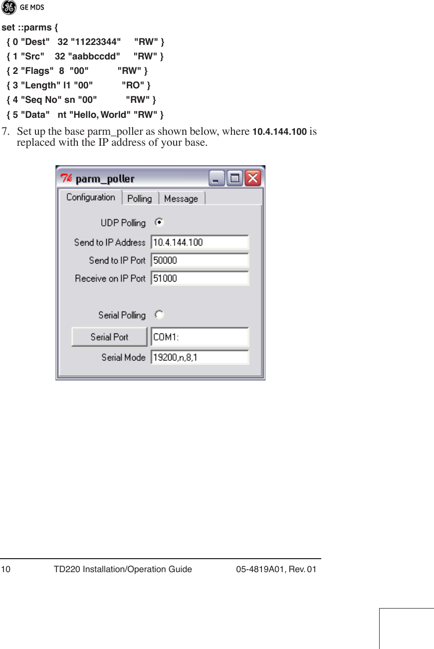
>
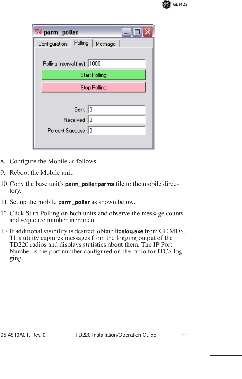
User manual
Contents
1.
User Manual
2.
User manual
User manual
Navigation menu
Upload a User Manual
Namespaces
Wiki Guide
HTML
PDF
Info
Views
User Manual
Discussion / Help
Navigation
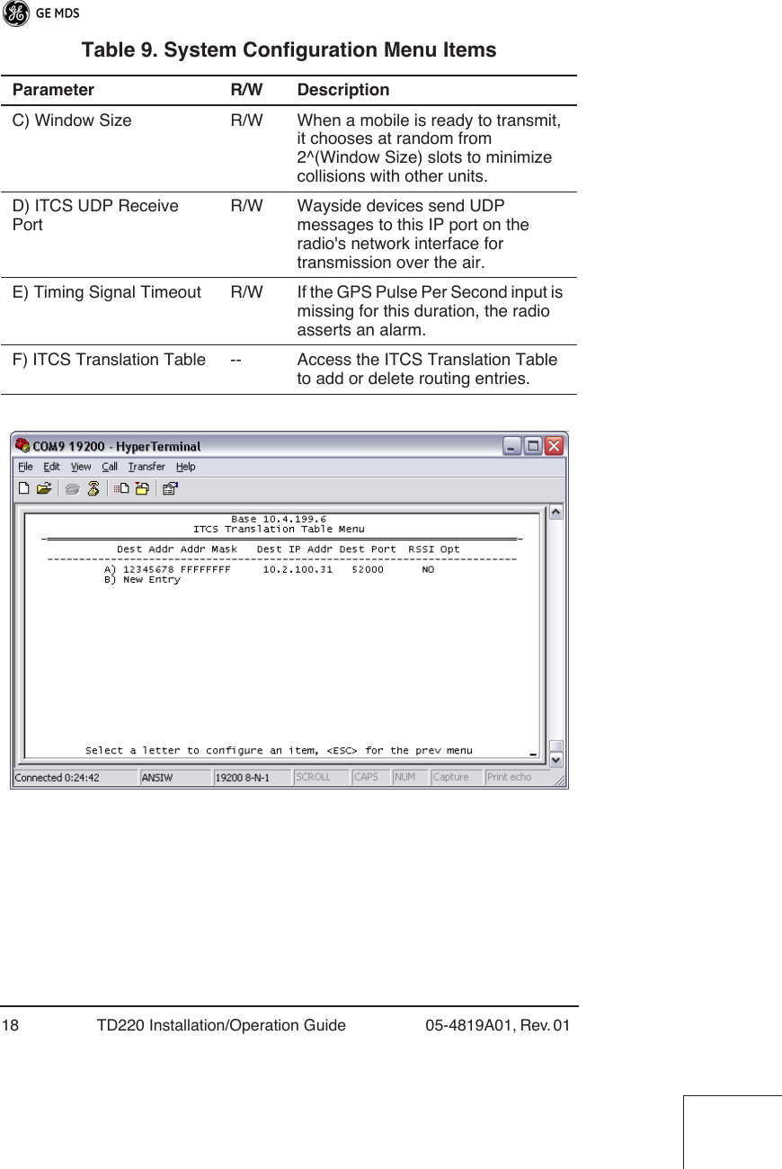
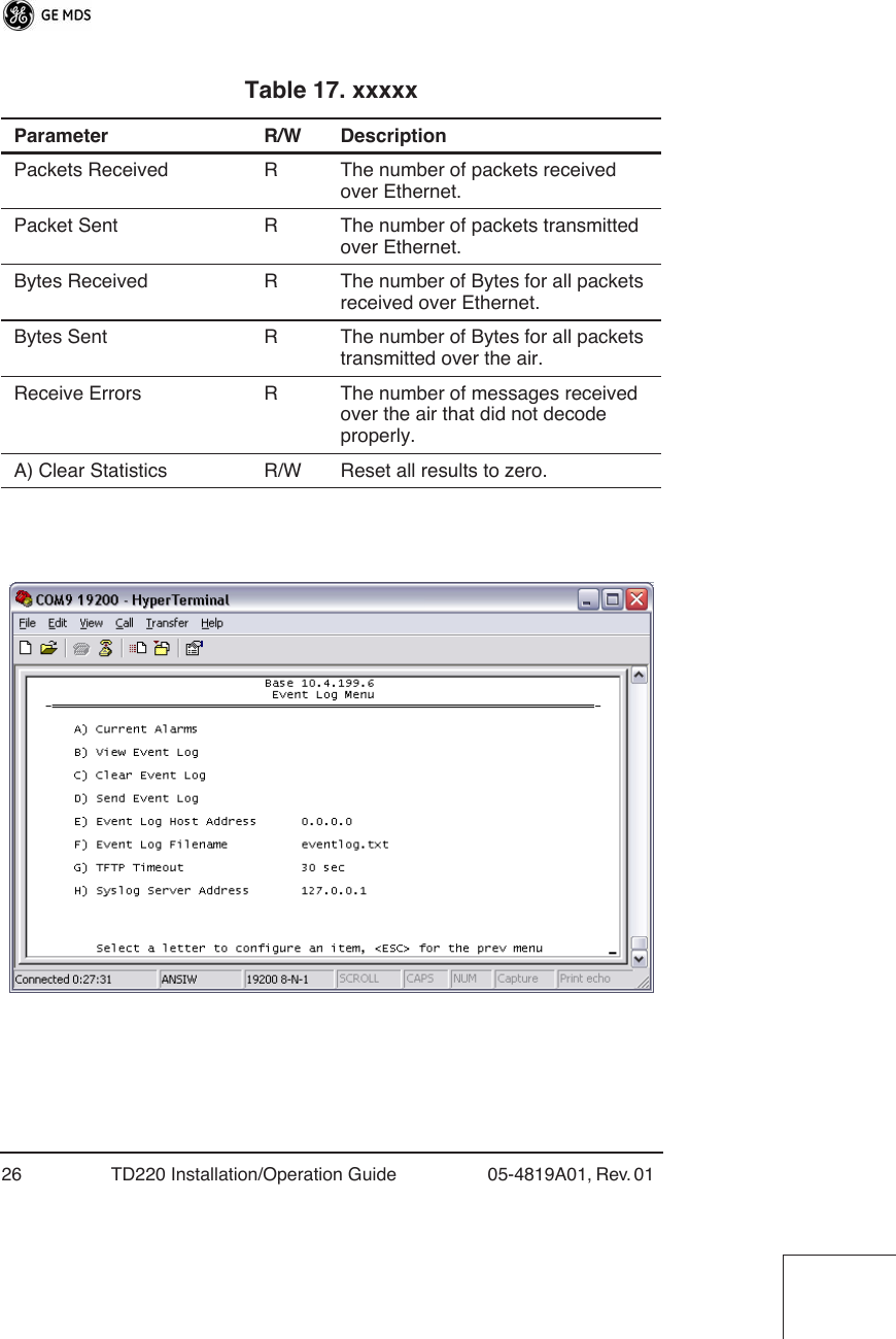

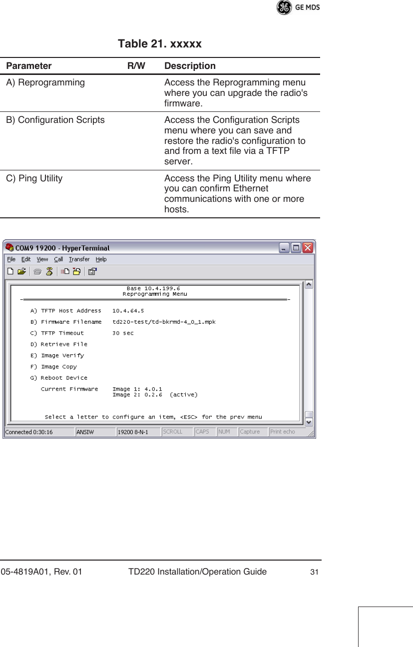
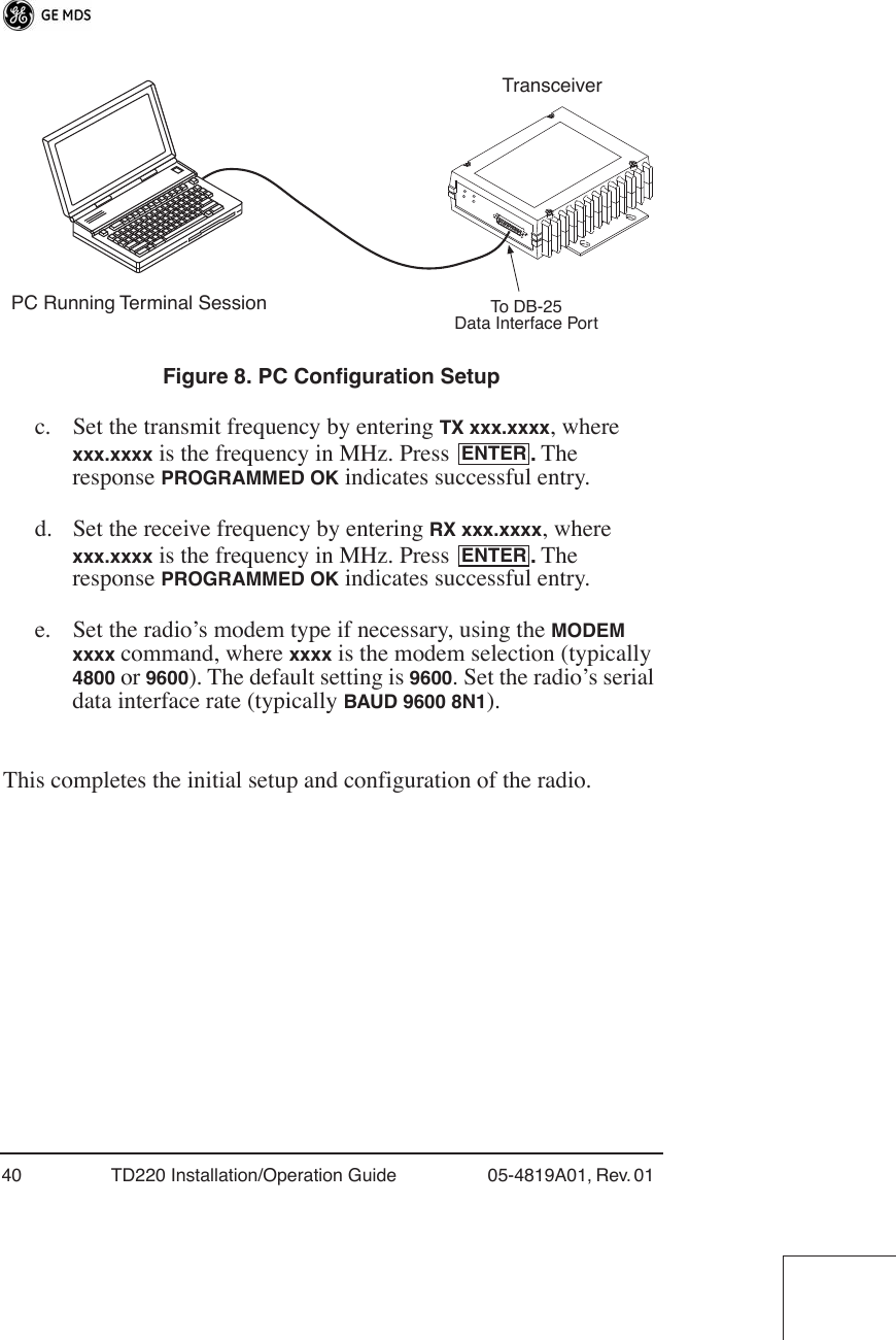
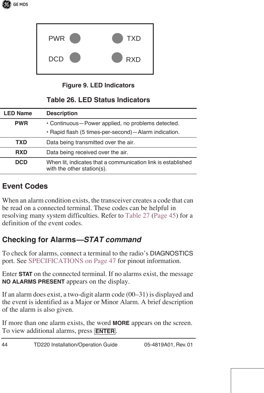
![05-4819A01, Rev. 01 TD220 Installation/Operation Guide 41SOFTWARE COMMAND SUMMARYTable 25 lists software commands commonly used during initial installation and setup of the transceiver. Detailed Command Usage(This section currently under revision)chan [chan # [rxfreq # [txfreq # [pwr # [bw # ] ] ] ] }Table 25. Command Summary Command Name FunctionBAUD [xxxx xxx] Sets radio’s serial data interface rate/format. Default setting is BAUD 9600 8N1.DKEY Dekey the radio (transmitter OFF). This is generally a radio test command.KEY Key the radio (transmitter ON). This is generally a radio test command.MODEM [xxxx] Set the modem characteristics of the radio.PWR [37–45] Set or display the transmit power setting.PTTSIG [ON, OFF] Set/display push-to-talk configuration.RSSI Display the Received Signal Strength Indication.RX [xxx.xxxx] Set or display receiver frequency.SER Display the radio serial number.SNR Signal-to-Noise Ratio (in dB).SPECTRUM [xxx.xx]Display internal spectrum analyzer, where xxx.xx characters denote center frequency in MHz. The command spectrum may be entered alone to view current operating channel.SREV Display the Software Revision Level.STAT Display radio status and alarms.TEMP Display the internal temperature of the radio in degrees C.TX [xxx.xxxx] Set or display the transmit frequency.](https://usermanual.wiki/GE-MDS/DS-TD220.User-manual/User-Guide-1031193-Page-43.png)
![42 TD220 Installation/Operation Guide 05-4819A01, Rev. 01 chan - channel # {all,0-8] rxfreq - receiver frequency txfreq - transmitter frequency pwr - power in watts (2, 5, 20, 25, 30) bw - bandwidth (12.5, 25)Examples:>chanChannel 1 RX 452.92500 MHz TX 452.92500 MHz PWR 30 Watts BW 25.000 KHz>chan allSelected LCT Channel is 0Channel 0 RX 450.00000 MHz TX 453.00000 MHz PWR 5 Watts BW 25.000 KHzChannel 1 RX 452.92500 MHz TX 452.92500 MHz PWR 30 Watts BW 25.000 KHzChannel 2 RX 452.95000 MHz TX 452.95000 MHz PWR 30 Watts BW 25.000 KHzChannel 3 RX 457.92500 MHz TX 457.92500 MHz PWR 30 Watts BW 25.000 KHzChannel 4 RX 457.95000 MHz TX 457.95000 MHz PWR 30 Watts BW 25.000 KHzChannel 5 RX 452.92500 MHz TX 452.92500 MHz PWR 30 Watts BW 25.000 KHzChannel 6 RX 452.95000 MHz TX 452.95000 MHz PWR 30 Watts BW 25.000 KHzChannel 7 RX 457.92500 MHz TX 457.92500 MHz PWR 30 Watts BW 25.000 KHzChannel 8 RX 457.95000 MHz TX 457.95000 MHz PWR 30 Watts BW 25.000 KHz>chan 8 rxfreq 453rxfreq 453Channel 8 RX 453.00000 MHz TX 457.95000 MHz PWR 30 Watts BW 25.000 KHz>chan 8 pwr 20pwr 20Channel 8 RX 453.00000 MHz TX 457.95000 MHz PWR 20 Watts BW 25.000 KHz>chan 8 bw 12.5bw 12.5](https://usermanual.wiki/GE-MDS/DS-TD220.User-manual/User-Guide-1031193-Page-44.png)
![05-4819A01, Rev. 01 TD220 Installation/Operation Guide 43Channel 8 RX 453.00000 MHz TX 457.95000 MHz PWR 20 Watts BW 12.500 KHz>mode test>selchan helpUsage: selchan [0-8] >selchan 8Channel Number 8>chanChannel 8 RX 453.00000 MHz TX 457.95000 MHz PWR 20 Watts BW 12.500 KHz>keyTRANSMITTER ENABLED>dkeyTRANSMITTER DISABLED>mode normalTROUBLESHOOTINGFor proper operation, all radios in the network must meet these basic requirements:• Adequate and stable primary power• Secure connections (RF, data and power)• A clear transmission path between stations• An efficient antenna system providing adequate received signal strength.• Proper programming of the transceiver’s operating parameters• The correct interface between the transceiver and the connected data equipment (correct cable wiring, proper data format, tim-ing, etc.)LED IndicatorsThe LED status indicators (Figure 9) are an important troubleshooting aid and should be checked whenever a problem is suspected. Table 26 describes the function of each status LED on the front panel of the radio.](https://usermanual.wiki/GE-MDS/DS-TD220.User-manual/User-Guide-1031193-Page-45.png)