GE MDS DS-TD220 Narrowband Wireless Transceiver User Manual Book1
GE MDS LLC Narrowband Wireless Transceiver Book1
GE MDS >
Contents
- 1. User Manual
- 2. User manual
User manual
Start-Up Guide
Firmware Release 1.x.x
MDS 05-4818A01, Rev. 02
OCTOBER 2008
DRAFT
MDS TD 220
217–222 MHz Data Transceiver

OPERATIONAL & SAFETY NOTICES
Concentrated energy from a directional antenna may pose a health hazard to
humans. Do not allow people to come closer to the antenna than the distances
listed in the table below when the transmitter is operating. More information on
RF exposure can be found online at the following website:
www.fcc.gov/oet/info/documents/bulletins.
Above data based on a 30-watt output level with a 100% duty cycle.
FCC Part 15 Notice
The transceiver is approved under Part 15 of the FCC Rules. Operation is subject to the following two con-
ditions: (1) this device may not cause harmful interference, and (2) this device must accept any interfer-
ence received, including interference that may cause undesired operation. Any unauthorized modification
or changes to this device without the express approval of Microwave Data Systems may void the user’s
authority to operate this device. Furthermore, this device is intended to be used only when installed in
accordance with the instructions outlined in this manual. Failure to comply with these instructions may
void the user’s authority to operate this device.
Antenna Gain vs. Recommended Safety Distance
Device complies with Power Density requirements at 20 cm
separation:
No
Required separation distance for 9 dBi antenna (in m): 2.53
RF Exposure
05-4819A01, Rev. 01 TD220 Installation/Operation Guide
1
INTRODUCTION
This guide presents basic installation and operating instructions for the
GE MDS TD 220 Series wireless transceiver.
The TD 220 operates in two bands and power levels:
• 25-Watts in the 220-222 MHz range
• 2-Watts in the 217-220 MHz range
The radio is a GMSK unit intended for bridging ITCS messages over
the air between locomotives and wayside devices. The data interface
is Ethernet, with UDP-encapsulated ITCS message payload.
Figure 1. TD 220 Data Transceiver
NOTE:
Some features may not be available on all units, based on the
options purchased and the applicable regulatory constraints
for the region in which the radio will operate.
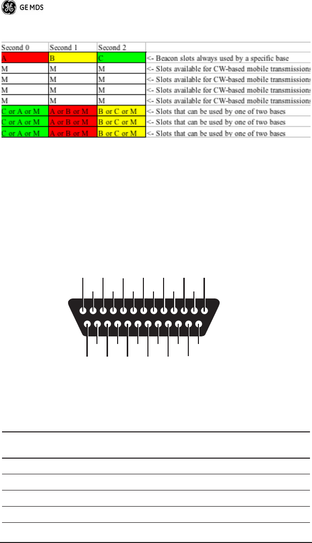
Each second is divided into 8 133-byte time slots. The first of the 8
timeslots each second is always reserved for bases to transmit beacon
information to the mobiles in the area. Following the beacon are 4 (or
5) time slots that are always reserved for mobiles to transmit. At the
end of each second, are 3 (or 2) time slots that can be used by bases or
mobiles. These slots are used with the following priority: the previous
base, the current base, and then mobiles. In other words, during second
1 in the table below, base A actually has priority over the last three
slots. If A does not use them, B can use them. If B does not use them,
mobiles can. Bases reserve these time slots with flags in the beacon.
This scheme maximizes the potential for utilizing all slots.
2 TD220 Installation/Operation Guide 05-4819A01, Rev. 01
DATA INTERFACES
DB-25
Figure 10 shows the pin arrangement for the DB-25
DATA INTER-
FACE
connector. Table 1 lists the pin functions and shows
input/output data for the connector.
Invisible place holder
Figure 2. DB-25 Pin Arrangement
(As viewed from outside the radio)
Table 1. Data Interface Pinouts
Pin No. Signal Name and Description Input/
Output
1
COM3_DCD
—Reserved. Input
2
COM2_TXD
—Descriptive text to be supplied. Input
3
COM2_RXD
—Descriptive text to be supplied. Output
4
COM2_RTS
—Descriptive text to be supplied. Input
13
12
11
10
9
8
7
6
5
4
3
2
1
24
23
22
21
20
19
18
17
16
15
14
25

05-4819A01, Rev. 01 TD220 Installation/Operation Guide
3
USB
The radio provides a USB Port conforming to version 1.1 of the USB
standard. This port is provided for future features such as ITCS log-
ging to text files on a memory stick. Consult GE MDS for information
on this feature. The pinout for this connector is given in the table
below.
5
COM2_CTS
—Descriptive text to be supplied. Output
6
COM3_TXD
—Reserved. Output
7
Ground
—Descriptive text to be supplied. --
8
COM2_DCD
—Descriptive text to be supplied. Output
9
COM3_CTS
—Reserved. Input
10
COM3_RTS
—Reserved. Output
11
COM3_DTR
—Reserved. Output
12
COM3_RXD
—Reserved. Input
13
Ground
—Descriptive text to be supplied. --
14
ETH_TX_H
—Descriptive text to be supplied. Output
15
ETH_TX_L
—Descriptive text to be supplied. Output
16
ETH_RX_H
—Descriptive text to be supplied. Input
17
ETH_RX_L
—Descriptive text to be supplied. Input
18
EXT_Key
—Reserved. Output
19
EXT_DET
—Reserved. Input
20
COM2_DTR
—Descriptive text to be supplied. Input
21
ALARM_OUT
—Reserved. Output
22
GPS_PPS_L
For TTL PPS, leave this pin open.
Input
23
GPS_PPS_H
For TTL PPS, use this input.
Input
24
COM1_RXD
—Descriptive text to be supplied. Input
25
COM1_TXD
—Descriptive text to be supplied. Output
Table 1. Data Interface Pinouts

4 TD220 Installation/Operation Guide 05-4819A01, Rev. 01
Power
The power connector is a screw-secured 2-pin connector.
The pin orientation (as looking into the connector) is shown below.
The following table shows how much current is required for receiving
or transmitting vs. input voltage and RF power output.
Table 2. USB Connector Pinouts
Pin Signal Name Description
1 PC_USB_+5V +5 VDC
2 USBD- USB Data Minus
3 USBD+ USB Data Plus
4 GROUND Chassis Ground
Table 3. Power Connector Pinouts
Pin Signal Name Input/Output Description
1
(Left)
PWR Input 13.8 Vdc input, 7A maximum
2
(Right)
GROUND Input Power return
Table 4. Current/Voltage Requirements vs. RF Output
Voltage (Vdc) RF Output (W) Current Required (A)
12 0 (RX) TBSL
12 2 TBSL
12 10 TBSL
12 25 TBSL
L R

05-4819A01, Rev. 01 TD220 Installation/Operation Guide
5
Antenna Connector
The Antenna Connector is a Type-N female connector with 50-Ohm
characteristic impedance.
Common Setup Tasks
Key the Transmitter for Test Purposes
1. Log in to the radio on its COM1 console using a serial terminal
emulator program.
2. Go to the Radio Configuration menu.
3. Select the frequency for the test transmission.
4. Select the RF Output Power to use. Note that power levels greater
than 2 Watts will timeout after a 5-second period by default.
Ensure ventilation with supplemental forced airflow if longer
durations are desired.
5. Select the Force TX Key menu option.
6. When finished, deselect the Force TX Key menu option.
Prepare the Network Interface for a Radio
Each radio is assigned an IP Address, a Netmask, and a Gateway IP
Address. The IP Address and Netmask should be chosen carefully.
The radio will network directly with other equipment with IP
Addresses that are on a common Subnet. IP Addresses that begin with
the same numerical IP address bits where the Netmask is one will be
on the same Subnet. For example, if the IP Address is 10.4.100.1 and
the Netmask is 255.255.0.0, the radio will attempt direct Ethernet
13.8 0 (RX) TBSL
13.8 2 TBSL
13.8 10 TBSL
13.8 25 TBSL
Table 4. Current/Voltage Requirements vs. RF Output
Voltage (Vdc) RF Output (W) Current Required (A)

6 TD220 Installation/Operation Guide 05-4819A01, Rev. 01
communication with any node whose IP Address begins with 10.4. If
a message is bound for a node outside of the 10.4 network, it will be
sent to the Gateway IP address instead so that it can be placed from the
radio's subnet onto another subnet.
1. Log in to the radio on its COM1 console using a serial terminal
emulator program.
2. Go to the IP Configuration menu.
3. Set the IP address of the radio, plus the Netmask and Gateway.
4. Go to the Maintenance/Tools Menu and select the Ping Utility.
5. Enter the IP address of a known node on the network.
6. Execute the Ping and observe the results. If the network interface
is working properly, Ping responses should be received.
Set Up a Base Unit
1. If not already done, complete steps from 3.2 above.
2. Log in to the radio.
3. Go to the System Configuration menu.
4. Set the unit to Base mode and reboot if necessary.
5. Set the base type (A, B, or C).
6. Set the window size. Mobiles will transmit in a randomly selected
available slot among 2^(Window Size) slots. For small networks,
this can be 1. For larger networks, use a Window Size that pro-
vides double or quadruple the number of mobiles expected under
one base at a time.
7. Set the IP Port on which the base will receive UDP messages from
wayside devices.
8. Set up an ITCS Translation Table. For test purposes, this may be
as simple as setting up one known address with a mask of all
“If’s”.
9. Verify Ethernet Link using the Ping utility in the Mainte-
nance/Tools Menu.
10. Begin sending UDP data.
11. Verify the TX LED illuminates and the radio begins transmitting
over the air.

05-4819A01, Rev. 01 TD220 Installation/Operation Guide
7
3.4 Set Up a Mobile Unit
1. If not already done, complete steps from 3.2 above.
2. Log in to the radio.
3. Go to the System Configuration menu.
4. Set the unit to Mobile mode and reboot if necessary.
5. Set the IP Port to which the mobile will send messages received
over the air.
6. Set the IP Port on which the mobile will accept incoming mes-
sages for transmission over the air.
7. Verify Ethernet Link using the Ping utility in the Mainte-
nance/Tools Menu.
8. Ensure at least one base is present in the neighborhood of this
radio so that it can detect beacons and synchronize timing.
9. Begin sending UDP data from a polling program.
10. Verify the TX LED illuminates and the radio begins transmitting
over the air.
3.5 Perform Test Polling
1. Set up the Base and Mobile as above.
2. Connect as shown in the following diagram. Note: this is for
bench testing only, i.e. not for sensitivity testing. Sensitivity test-
ing requires complete RF isolation or mixed operation to prevent
the leakage path from being the dominant RF path between units.
For bench testing, use attenuation so that the signal level at every
unit that is participating is around -70 to -50 dBm.

8 TD220 Installation/Operation Guide 05-4819A01, Rev. 01
Invisible place holder
Figure 3. Test Setup
3. Configure the Base as follows in the radio software:
05-4819A01, Rev. 01 TD220 Installation/Operation Guide
9
4. Reboot the Base
5. Obtain the Parametric Poller (parm_poller.exe) from GE MDS.
This utility saves its settings to
parm_poller.ini
in the current direc-
tory, so make one directory for the base and a different directory
for the mobile.
6. In the base directory, create the parm_poller data configuration file
(
parm_poller.parms
) as shown below.
10 TD220 Installation/Operation Guide 05-4819A01, Rev. 01
set ::parms {
{ 0 "Dest" 32 "11223344" "RW" }
{ 1 "Src" 32 "aabbccdd" "RW" }
{ 2 "Flags" 8 "00" "RW" }
{ 3 "Length" l1 "00" "RO" }
{ 4 "Seq No" sn "00" "RW" }
{ 5 "Data" nt "Hello, World" "RW" }
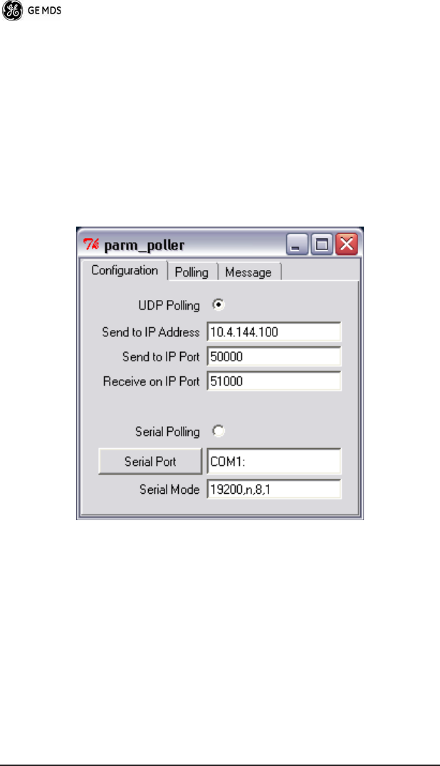
7. Set up the base parm_poller as shown below, where
10.4.144.100
is
replaced with the IP address of your base.
05-4819A01, Rev. 01 TD220 Installation/Operation Guide
11
8. Configure the Mobile as follows:
9. Reboot the Mobile unit.
10. Copy the base unit's
parm_poller.parms
file to the mobile direc-
tory.
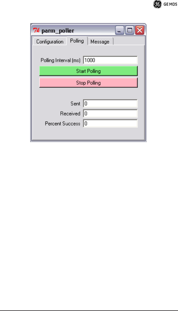
11. Set up the mobile
parm_poller
as shown below.
12. Click Start Polling on both units and observe the message counts
and sequence number increment.
13. If additional visibility is desired, obtain
itcslog.exe
from GE MDS.
This utility captures messages from the logging output of the
TD220 radios and displays statistics about them. The IP Port
Number is the port number configured on the radio for ITCS log-
ging.
12 TD220 Installation/Operation Guide 05-4819A01, Rev. 01
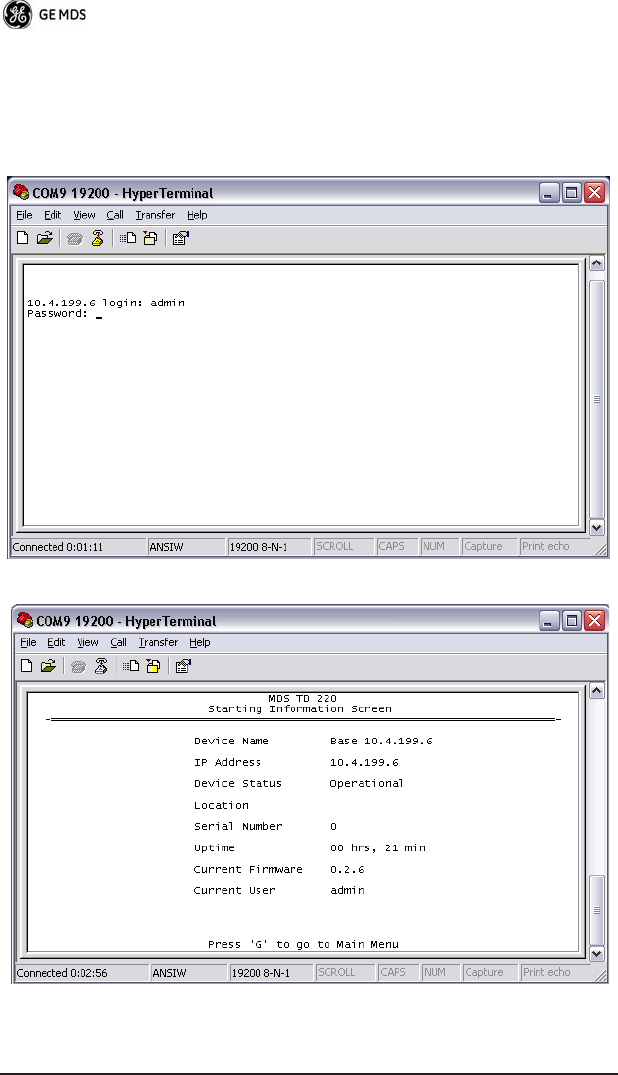
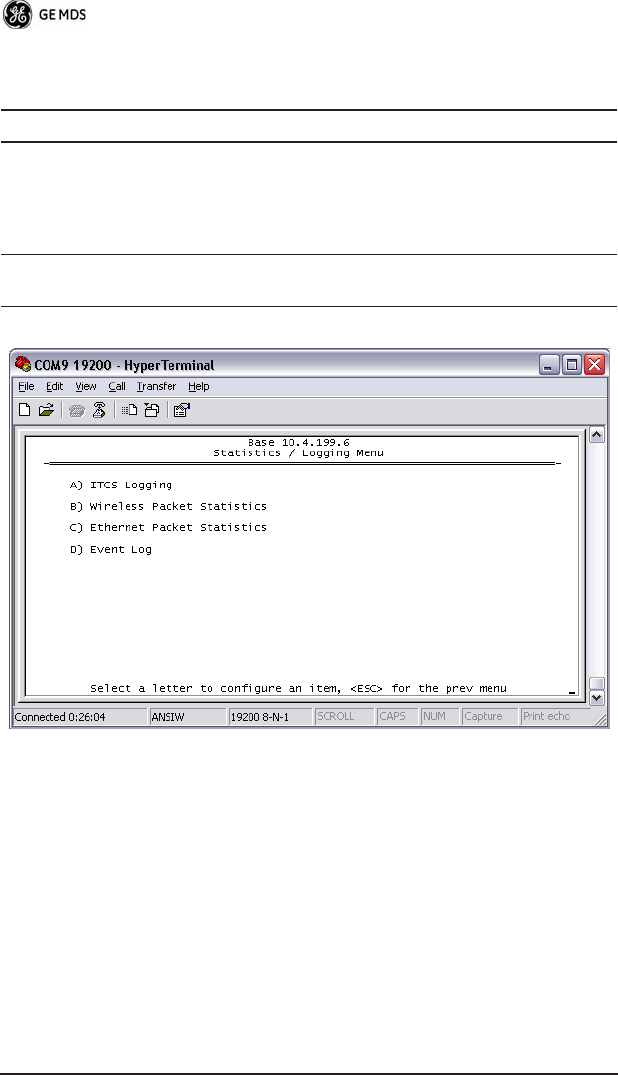
Description of Menu Interface
Login with user name
admin
, password
admin
.
When logged in, the Starting Information Screen is displayed.
05-4819A01, Rev. 01 TD220 Installation/Operation Guide
13
R* - This parameter is writable from another menu.
Table 5. Starting Information Screen Items
Parameter R/W Description
Device Name R* User-configured name for this radio. Set this
from the Device Names menu.
IP Address R* IP Address for this radio. Set this from the IP
Networking menu.
Device Status R “Initializing” during startup and/or internal RF
deck reprogramming, “Operational” when
functioning, “Alarmed” when error
condition(s) exist.
Location R* User-configured location for this radio. Set
this from the Device Names menu.
Serial Number R The manufacturer's serial number for this
radio. Set only in the factory.
Uptime R Elapsed time since the radio was started.
Current
Firmware
R* The version number of the currently operating
firmware. Reprogram firmware from the
Reprogramming Menu.
Current User R Login level

14 TD220 Installation/Operation Guide 05-4819A01, Rev. 01
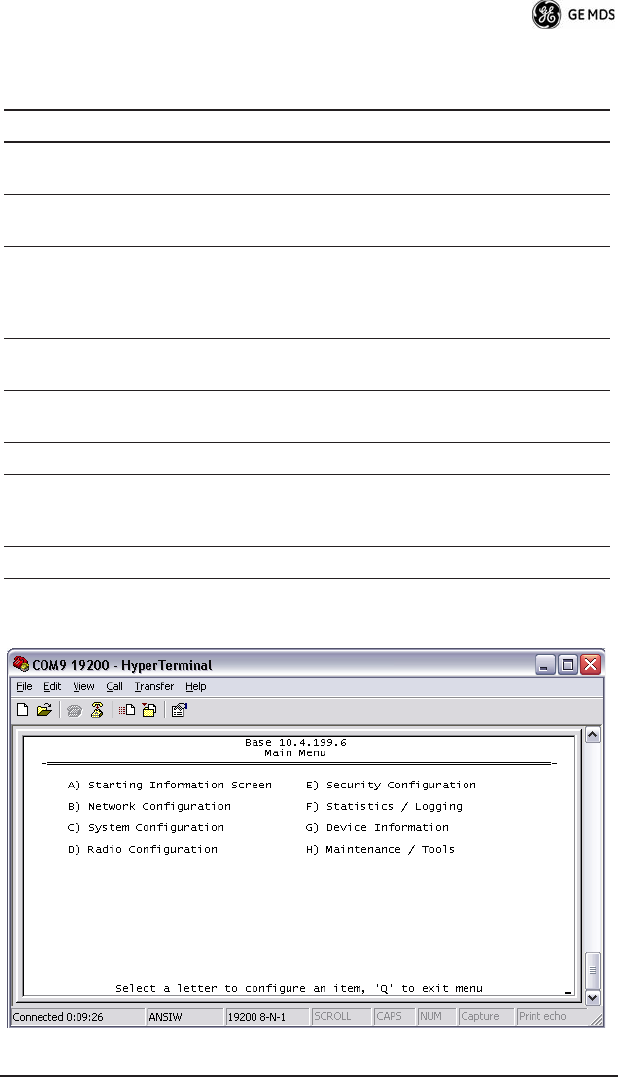
Table 6. Main Menu Items
Parameter R/W Description
A) Starting Information
Screen
Returns to the opening menu
B) Network Configuration Set the radio's IP Address, Netmask,
and Gateway
C) System Configuration Set the radio's Mode (Base/Mobile)
and other application-specific
operating parameters including the
Base's ITCS translation table.
D) Radio Configuration Set the radio's Frequencies, Base
transmit slot allocation (3/4), RF
Power Output, and access the Force
TX Key function.
E) Security Configuration Set up how the radio may be
accessed
F) Statistics / Logging Obtain historical and current
statistics about the radio's payload
performance, and access ITCS
Logging configuration.
G) Device Information Set up the radio's Date, Time,
Console Baud Rate and Names.
Review the radio's Model, Serial
Number, and Uptime.
H) Maintenance / Tools Access the radio's Firmware
Reprogramming, Configuration
Script, and Ping Utility menus.

05-4819A01, Rev. 01 TD220 Installation/Operation Guide
15
Table 7. Network Configuration Menu Items
Parameter R/W Description
A) IP Configuration Access the IP Configuration menu to
set the IP Address, Netmask, and
Gateway IP Address.
Ethernet Address R Displays the hardware MAC address
for the Ethernet port.
16 TD220 Installation/Operation Guide 05-4819A01, Rev. 01
Note: The IP Address and IP Gateway must be on the same subnet or a
Network Interface error will occur.
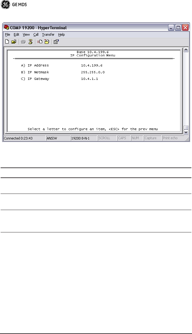
Table 8. IP Configuration Menu Items
Parameter R/W Description
IP Address R/W The IP address that this radio will
use for its Ethernet interface.
IP Netmask R/W The subnet mask for the network
this radio is part of.
C) IP Gateway R/W The IP address of the gateway that
will pass traffic from the radio's
subnet to nodes on other networks.
05-4819A01, Rev. 01 TD220 Installation/Operation Guide
17
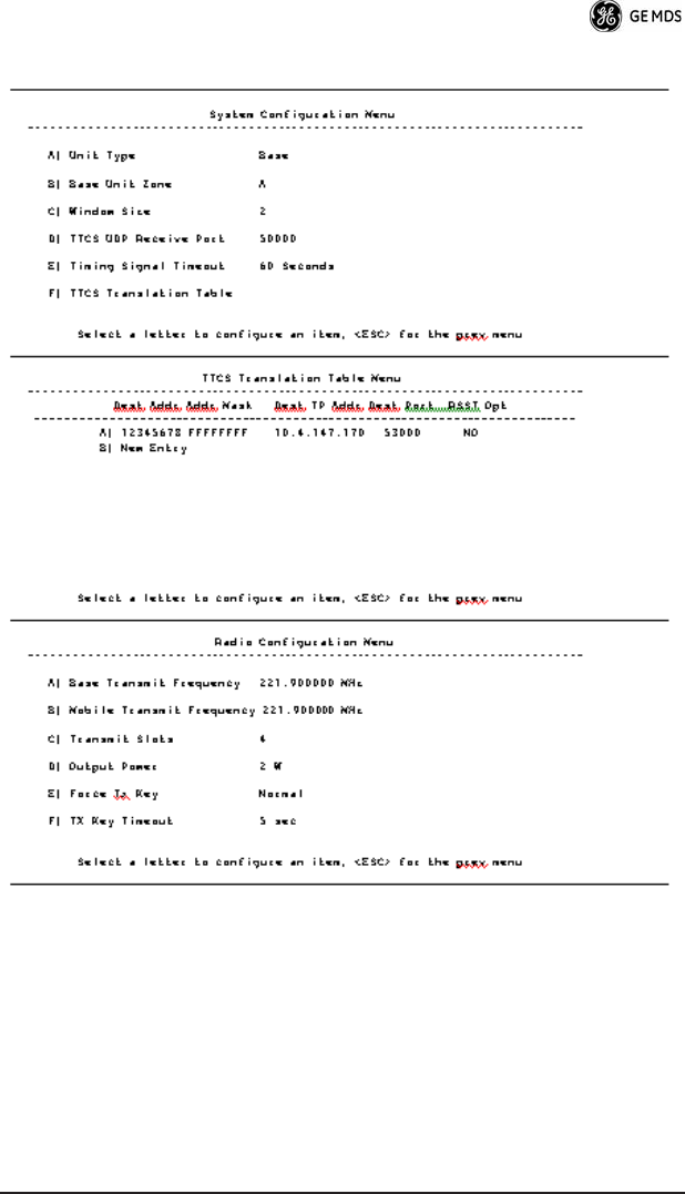
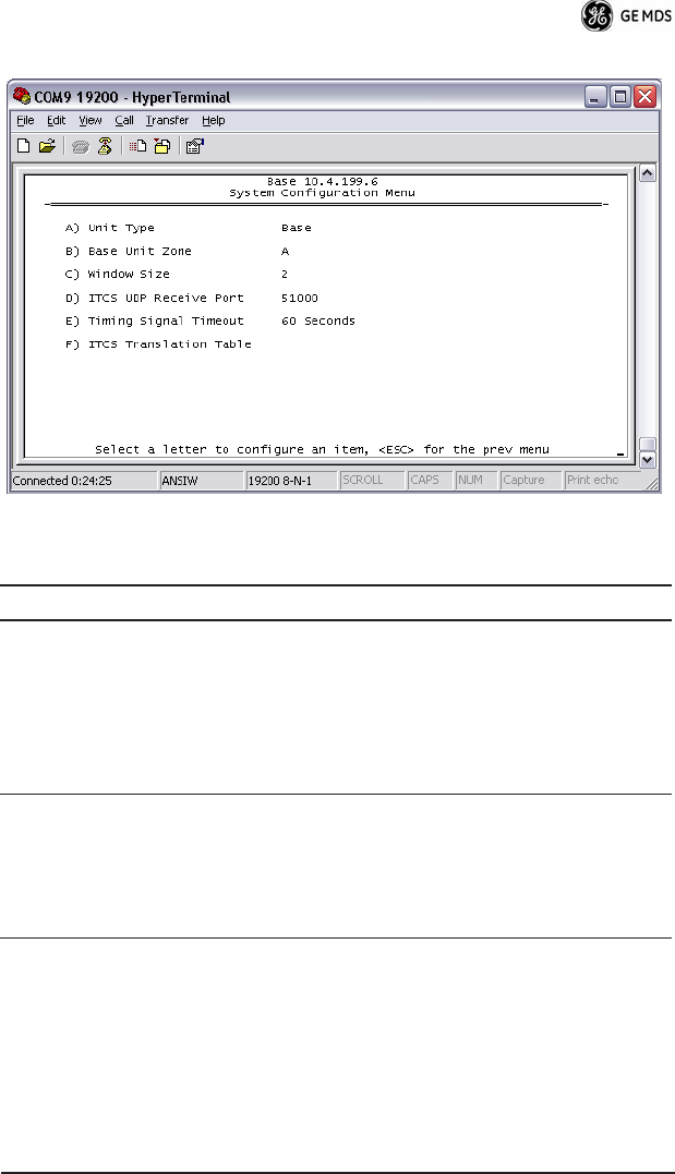
Table 9. System Configuration Menu Items
Parameter R/W Description
A) Unit Type R/W Bases send beacons out once per
epoch and coordinate downstream
messages. Mobiles listen to bases
to identify free slots, and then select
random slots in which to place their
upstream messages.
B) Base Unit Zone R/W Bases are one of three types, A, B,
and C. Each base coordinates slots
in the epoch assigned to that base
and transmits downstream. Base
types repeat along lines of track (A,
B, C, A, B, …)

18 TD220 Installation/Operation Guide 05-4819A01, Rev. 01
C) Window Size R/W When a mobile is ready to transmit,
it chooses at random from
2^(Window Size) slots to minimize
collisions with other units.
D) ITCS UDP Receive
Port
R/W Wayside devices send UDP
messages to this IP port on the
radio's network interface for
transmission over the air.
E) Timing Signal Timeout R/W If the GPS Pulse Per Second input is
missing for this duration, the radio
asserts an alarm.
F) ITCS Translation Table -- Access the ITCS Translation Table
to add or delete routing entries.
Table 9. System Configuration Menu Items
Parameter R/W Description

05-4819A01, Rev. 01 TD220 Installation/Operation Guide
19
The following chart shows how RSSI Data (shaded portion) is
prepended to standard ITCS Data within the UDP packet.
Table 10. ITCS Translation Table Menu Items
Parameter R/W Description
A) ITCS Translation Table
Entry
R/W Each entry in this table contains a
32-bit Destination ITCS Address, a
32-bit ITCS Address Mask, an IP
Address and port, and the RSSI
Option. Any incoming ITCS
message is bitwise anded with the
mask. If the result matches the
Destination ITCS Address, the
message is sent to the IP Address
and Port given. If the RSSI Option is
“yes”, the over the air Received
Signal Strength Indication is
prepended to the data message in
the UDP transmission.
Table 11. RSSI Data in Relation to ITCS Data
N
on-ITCS Header Data ITCS L2 Header Data
A
ddress ID Length RSSI
Type
RSSI
Data
Destination
ITCS
Address
Source
ITCS
Address
4
Bytes 1 Byte 1 Byte 1 Byte 1 Byte 4 Bytes 4 Bytes N
Bytes
A
lways
0
0 for
RSSI
2 0 Signed
value
from
–120 to
–30 dBm
20 TD220 Installation/Operation Guide 05-4819A01, Rev. 01
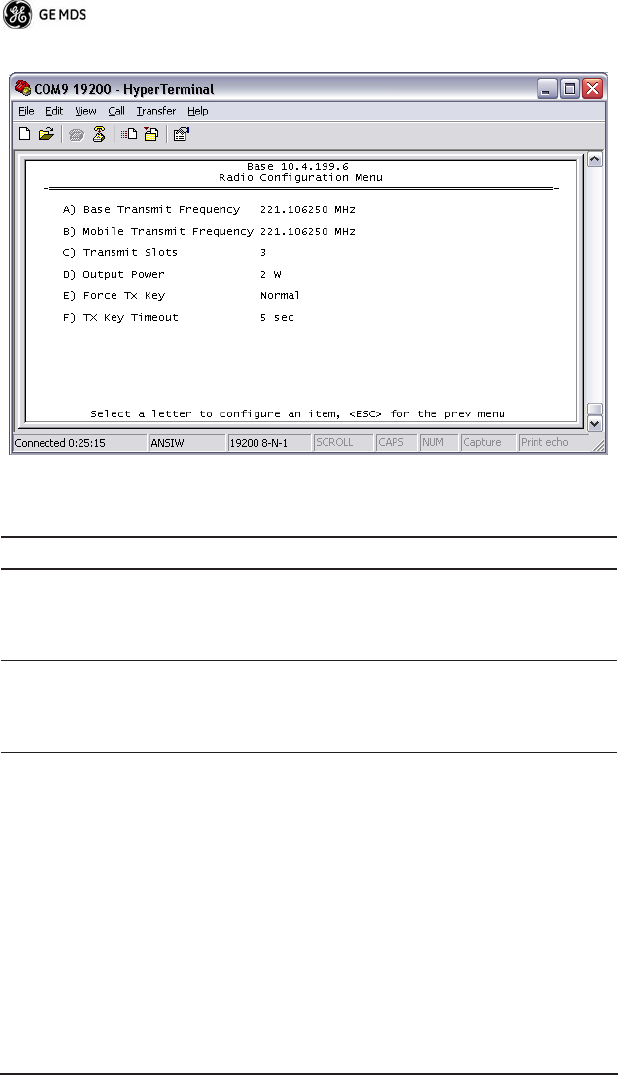
Table 12. Radio Configuration Menu Items
Parameter R/W Description
A) Base Transmit
Frequency
R/W The frequency in the 217.44625 to
221.95625 MHz range that the Base
Units use for over the air
transmissions.
B) Mobile Transmit
Frequency
R/W The frequency in the 217.44625 to
221.95625 MHz range that the
Mobile Units use for over the air
transmissions.
05-4819A01, Rev. 01 TD220 Installation/Operation Guide
21
C) Base Transmit Slots R/W The number of slots within each
8-slot second that are reserved for
base transmissions if needed.
NOTE: This parameter must match
on all bases and mobiles in the
network.
D) Output Power R/W The RF Output Power from 2 to 25
Watts with which the radio transmits.
E) Force TX Key R/W “Normal” to allow the radio to
operate in data mode, “Forced” to
key the transmitter for test purposes.
F) TX Key Timeout R/W If TX Key is Forced, the radio will
automatically De-Key after this
timeout.
Table 12. Radio Configuration Menu Items
Parameter R/W Description
22 TD220 Installation/Operation Guide 05-4819A01, Rev. 01
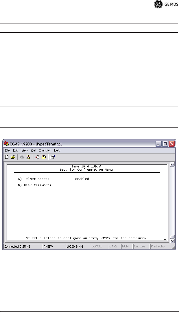
Table 13. Security Configuration Menu Items
Parameter R/W Description
A) Telnet Access R/W If “enabled”, the radio allows users
to Telnet to the radio via Ethernet. If
“disabled”, users must manage the
radio via SNMP or the serial
console.
B) User Passwords Allows modification of the admin
password.
05-4819A01, Rev. 01 TD220 Installation/Operation Guide
23
Table 14. xxxxx
Parameter R/W Description
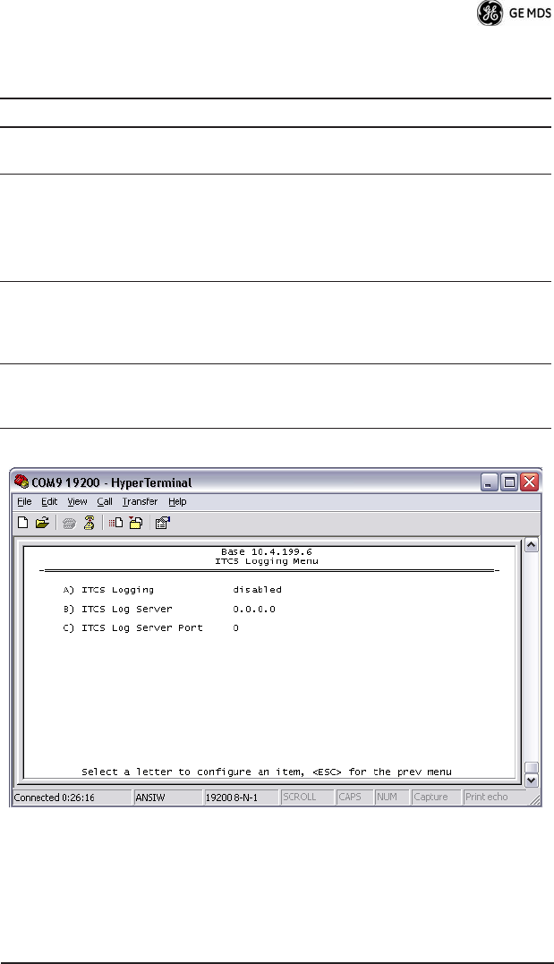
A) ITCS Logging Access the ITCS Logging
configuration menu.
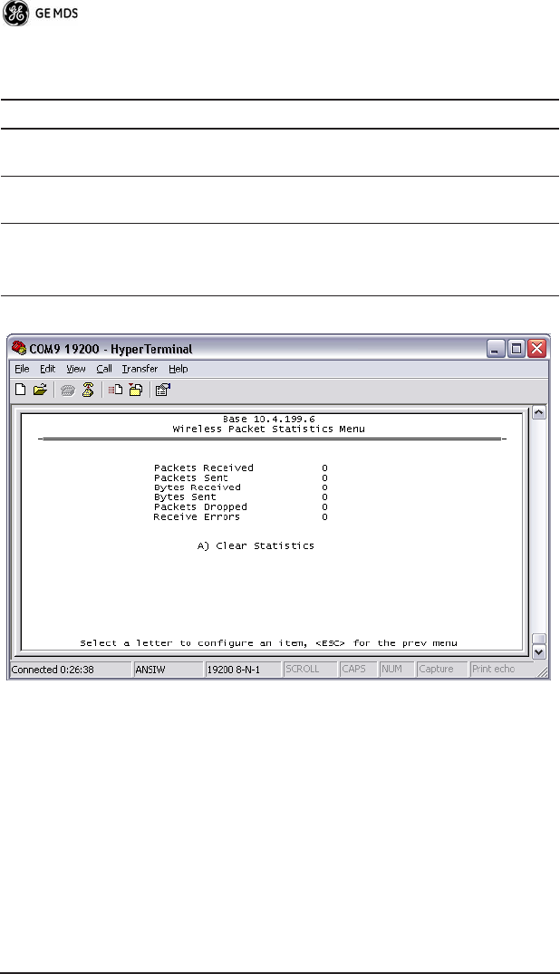
B) Wireless Packet
Statistics
Access the Wireless Packet
Statistics menu where you can view
the number of messages passed
over the air.
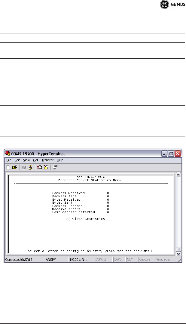
C) Ethernet Packet
Statistics
Access the Ethernet Packet
Statistics menu where you can view
the number of messages passed via
Ethernet.
D) Event Log Access the Event Log menu where
you can view the radio's log of
system events and alarms.
24 TD220 Installation/Operation Guide 05-4819A01, Rev. 01
Table 15. xxxxx
Parameter R/W Description
A) ITCS Logging R/W If “enabled”, send UDP messages to
a logging host.
B) ITCS Log Server R/W The IP address to send UDP
messages for logging ITCS traffic.
C) ITCS Log Server Port R/W The IP port number to send UDP
messages for logging ITCS traffic.
05-4819A01, Rev. 01 TD220 Installation/Operation Guide 25
Table 16. xxxxx
Parameter R/W Description
Packets Received R The number of packets received
over the air.
Packet Sent R The number of packets transmitted
over the air.
Bytes Received R The number of Bytes for all packets
received over the air.
Bytes Sent R The number of Bytes for all packets
transmitted over the air.
Receive Errors R The number of messages received
over the air that did not decode
properly.
A) Clear Statistics R/W Reset all results to zero.
26 TD220 Installation/Operation Guide 05-4819A01, Rev. 01
Table 17. xxxxx
Parameter R/W Description
Packets Received R The number of packets received
over Ethernet.
Packet Sent R The number of packets transmitted
over Ethernet.
Bytes Received R The number of Bytes for all packets
received over Ethernet.
Bytes Sent R The number of Bytes for all packets
transmitted over the air.
Receive Errors R The number of messages received
over the air that did not decode
properly.
A) Clear Statistics R/W Reset all results to zero.

05-4819A01, Rev. 01 TD220 Installation/Operation Guide 27
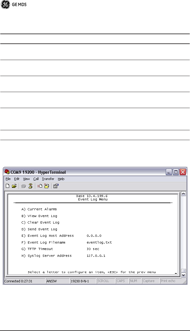
Table 18. xxxxx
Parameter R/W Description
A) Current Alarms Display a list of the alarms currently
active within the radio.
B) View Event Log Scroll through the historical list of
radio events and alarms.
C) Clear Event Log Erase all history of radio events and
alarms.
D) Send Event Log Begin a TFTP transfer of the
historical list of all radio events to the
IP Address given by “Event Log Host
Address”.
E) Event Log Host
Address
R/W The IP Address of the server that will
accept TFTP transfer of the Event
Log.
F) Event Log Filename R/W The file name on the server for the
event log.
G) TFTP Timeout R/W If the radio cannot reach the TFTP
server, it waits this long before
giving up at each step in the
process.
H) Syslog Server Address R/W As events and alarms occur in real
time, send them via the standard
SYSLOG protocol (RFC 3164) to the
server at this IP Address.
28 TD220 Installation/Operation Guide 05-4819A01, Rev. 01
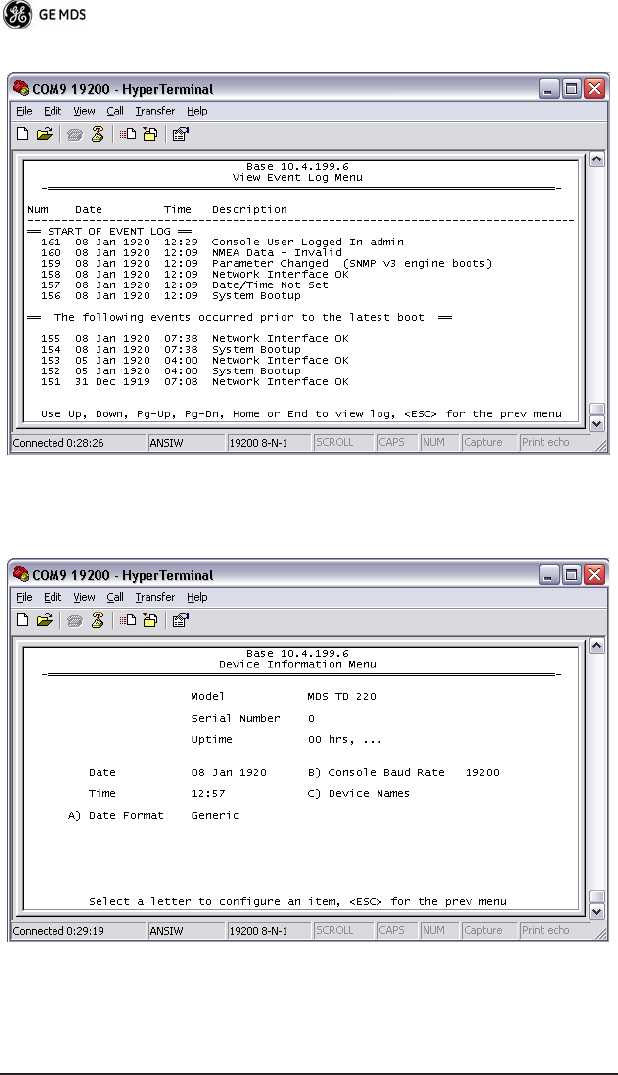
This screen displays the event number, date and time, and event or
alarm for each occurrence.
05-4819A01, Rev. 01 TD220 Installation/Operation Guide 29
Table 19. xxxxx
Parameter R/W Description
Model R The Model Type of the radio.
Serial Number R The factory-assigned unique radio
Serial Number.
Uptime R The number of elapsed hours,
minutes, and seconds since the
radio last rebooted.
Date R The Date from the GPS receiver.
Time R The Time from the GPS receiver.
A) Date Format R/W Change how the date and time are
displayed.
B) Console Baud Rate R/W The serial port rate the console will
communicate at.
C) Device Names Access the Device Names menu
where you can modify the
user-programmable name strings for
this radio.
30 TD220 Installation/Operation Guide 05-4819A01, Rev. 01
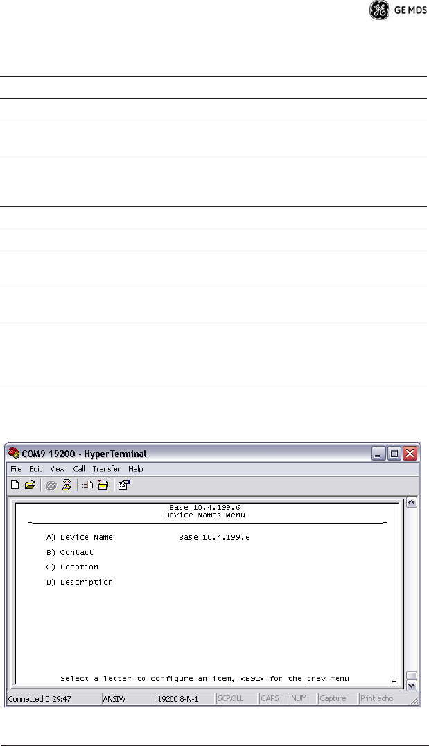
Table 20. xxxxx
Parameter R/W Description
A) Device Name R/W Free-form field where you can
enter a nickname for this radio.
B) Contact R/W Free-form field where you can
indicate who to contact in case the
radio needs service.
C) Location R/W Free-form field where you can
describe the site at which the radio
is installed.
D) Description R/W Free-form field where you can
enter details describing this radio.
05-4819A01, Rev. 01 TD220 Installation/Operation Guide 31
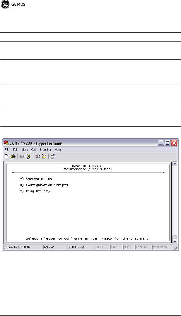
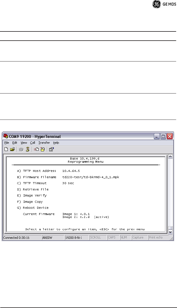
Table 21. xxxxx
Parameter R/W Description
A) Reprogramming Access the Reprogramming menu
where you can upgrade the radio's
firmware.
B) Configuration Scripts Access the Configuration Scripts
menu where you can save and
restore the radio's configuration to
and from a text file via a TFTP
server.
C) Ping Utility Access the Ping Utility menu where
you can confirm Ethernet
communications with one or more
hosts.

32 TD220 Installation/Operation Guide 05-4819A01, Rev. 01
Table 22. xxxxx
Parameter R/W Description
A) TFTP Host Address R/W The IP address of the TFTP server
from which you will download a new
firmware image.
B) Firmware Filename R/W The file name for the firmware
image. This file must exist on the
server.
C) TFTP Timeout R/W If the radio cannot reach the TFTP
server, it waits this long before
giving up at each step in the
process.
D) Retrieve File Command the radio to request the
firmware image from the TFTP
server.
E) Image Verify Command the radio to perform a
check of the firmware image in
memory.
F) Image Copy Command the radio to copy the
active firmware image to the inactive
position.
G) Reboot Device Command the radio to restart using
one of the firmware images
Current Firmware Shows the version number of both
firmware images, plus which one is
currently executing.
05-4819A01, Rev. 01 TD220 Installation/Operation Guide 33
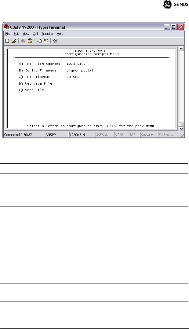
Table 23. xxxxx
Parameter R/W Description
A) TFTP Host Address R/W The IP address of the TFTP server
to or from which you will upload
or download a configuration
script.
B) Config Filename R/W The filename to or from which
you will save or restore the
radio's configuration.
C) TFTP Timeout R/W If the radio cannot reach the TFTP
server, it waits this long before
giving up at each step in the pro-
cess.
D) Retrieve File Command the radio to get the file
from the TFTP server.
E) Send File Command the radio to send the file
to the TFTP server.
34 TD220 Installation/Operation Guide 05-4819A01, Rev. 01
Configuration scripts are used to store and duplicate radio settings. To
use this facility, send the configuration file from a radio to the TFTP
server. It can then be archived or edited and retrieved from the same
or different radios. For more information, contact GE MDS.
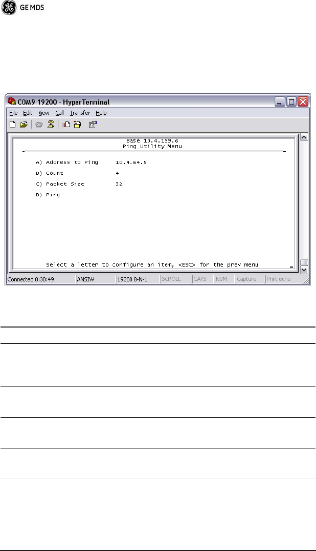
Table 24. xxxxx
Parameter R/W Description
A) Address to Ping R/W The IP address of the network host
to which you will send test mes-
sages.
B) Count R/W The number of test messages you
will send.
C) Packet Size R/W The number of Bytes each test
message will contain.
D) Ping Command the radio to begin the
ping test.
05-4819A01, Rev. 01 TD220 Installation/Operation Guide 35
Troubleshooting
Here are some tips to help resolve issues when operating the TD220.
SymptomPossible Cause
Radio shows messages are received via Ethernet, but it will not
transmit over the air.Radio is alarmed.
XXXXXXXXXXOriginal Follows...Under RevisionXXXXXXXXX
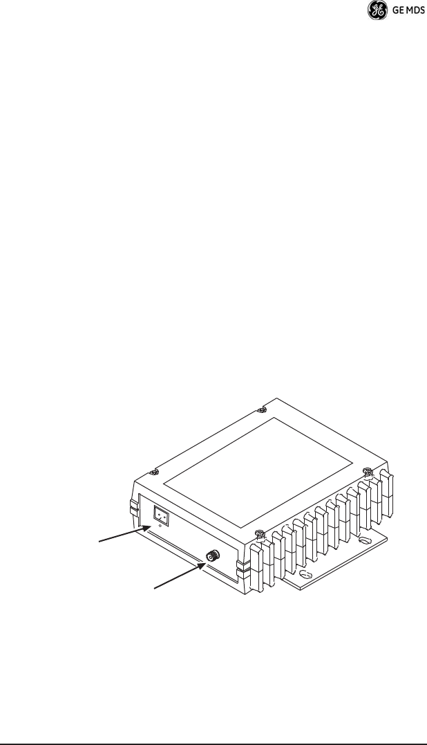
Front Panel Connectors
Figure 4 and Figure 5 show the interface connectors and indicators on
the transceiver’s front an d rear panels. These items are referenced in
the installation steps given later in this guide.
Invisible place holder
Figure 4. Antenna & DC Power Connectors
Antenna
(Mini-UHF)
Power Input
(10.5 to 16 Vdc @ 8A)

36 TD220 Installation/Operation Guide 05-4819A01, Rev. 01
Invisible place holder
Figure 5. Data Interface Connector & LED Status Panel
INSTALLATION
There are three main requirements for installing the transceiver:
• Adequate and stable primary power
• An efficient and properly installed antenna system
• Correct data connections between the transceiver and the data
device.
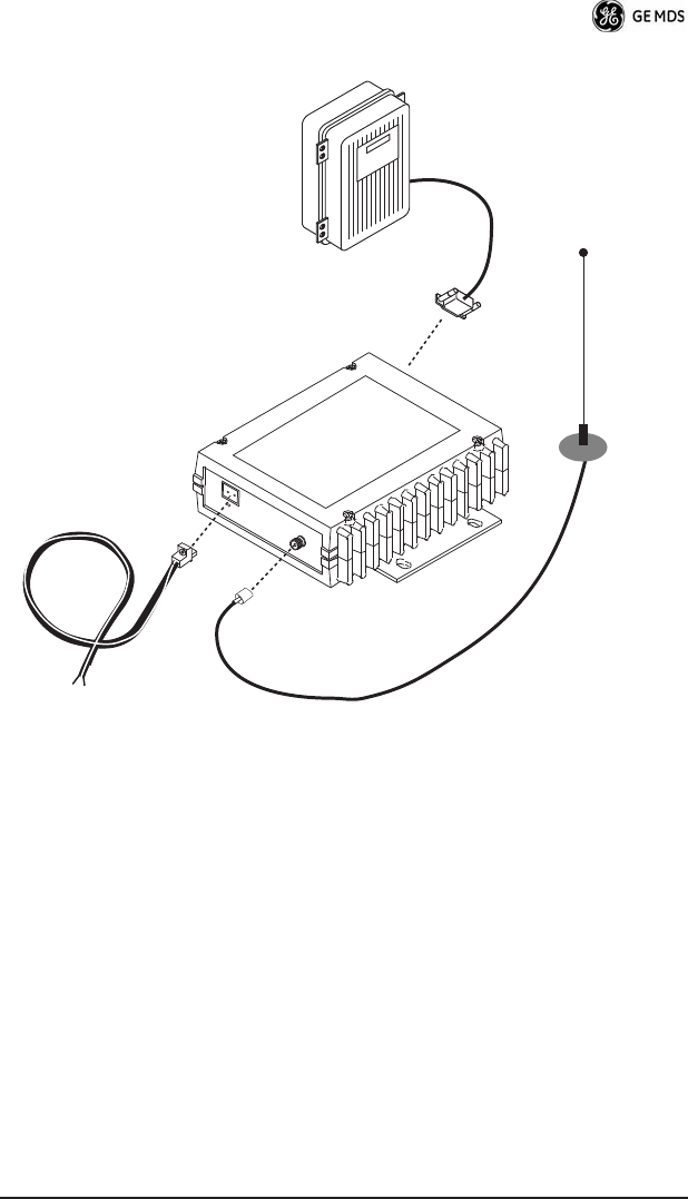
Figure 6 shows a typical station arrangement. This is followed by
step-by-step procedures for installing the transceiver and making front
and rear panel connections.
LED Indicator Panel
(See inset above)
Data Interface
(DB-25)
PWR
DCD
TXD
RXD
05-4819A01, Rev. 01 TD220 Installation/Operation Guide 37
Figure 6. Typical Station Arrangement
Installation Steps
Below are the basic steps for installing the transceiver. Refer to
Figure 6 as necessary to make the cable connections.
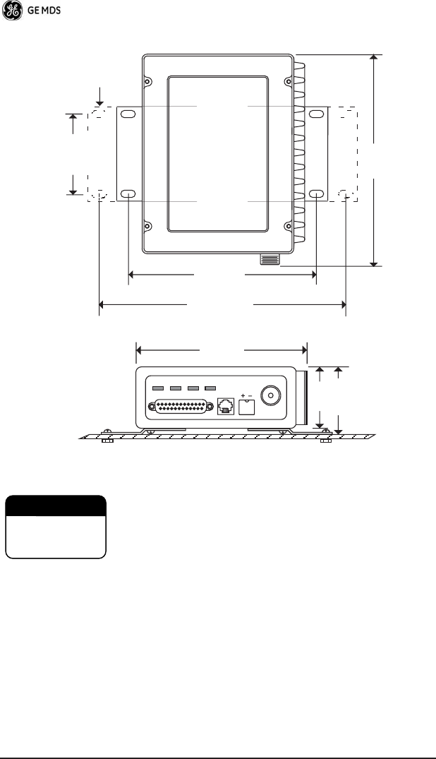
1. Mount the transceiver to a stable surface using the brackets
supplied with the radio. Begin by attaching the radio’s mounting
brackets to the bottom of the transceiver case (if not already
attached) using the four 6-32 x 1/4 inch (6 mm) screws supplied.
Figure 7 shows the mounting bracket dimensions.
NOTE: To prevent moisture from entering the radio, do not mount the
case with the cable connectors pointing up. Also, dress all
cables to prevent moisture from running along the cables and
into the radio.
DC POWER CABLE
10.5—16 VDC @ 8A
Negative Ground
DATA EQUIPMENT
ANTENNA
SYSTEM
LOW-LOSS
COAXIAL CABLE
(50 Ohm)
RADIO
TRANSCEIVER
38 TD220 Installation/Operation Guide 05-4819A01, Rev. 01
Invisible place holder
Figure 7. Transceiver Mounting Bracket Dimensions
Using screws longer than 1/4 inch (6 mm) to attach the
brackets to the radio may damage the internal PC
board. Use only the supplied screws.
2. Install the antenna and feedline for the station. The antenna
used with the transceiver must be designed to operate in the
radio’s frequency band, and be mounted in a location that pro-
vides a clear, path to the other associated station(s). Use low loss
coaxial feedline and keep the cable as short as possible.
8.5"
216 mm
1.75"
4.44 CM
6.63"
168 mm
2.75"
70 mm
7.25"
184 mm
ALTERNATE
POSITION
5.625"
143 mm
2.25"
57 mm
2.0"
50 mm
CAUTION
POSSIBLE
EQUIPMENT
DAMAGE

05-4819A01, Rev. 01 TD220 Installation/Operation Guide 39
3. Connect the data equipment to the DATA INTERFACE connec-
tor. Check SPECIFICATIONS on Page 47 for pin wiring details.
Note: The radio’s DIAGNOSTICS port is used for reprogramming
the radio’s firmware.
4. Connect primary power to the transceiver. Power applied must
be within 10.5–16 Vdc and capable of continuously providing at
least 8 Amperes. A power connector with is provided with each
unit (see Figure 6).
The transceiver is designed for use with nega-
tive-ground systems only. The power supply should be
equipped with overload protection (NEC Class 2 rating),
to protect against a short circuit between its output ter-
minals and the radio’s power connector.
5. Set the radio’s configuration. The transceiver is designed for
quick installation with a minimum of software configuration
required.
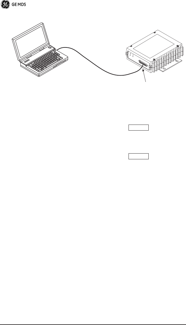
a. Connect a PC to the transceiver’s DATA INTERFACE connec-
tor as shown in Figure 8. If desired, a cable may be built using
the information shown on Page 47 of this guide.
b. Launch a terminal communications program, such as Hyper-
Terminal (included with most WindowsTM systems). Press the
key a few times (at half-second intervals) to receive
the ready “>” prompt on the screen.
NOTE: To prevent unintended keying of the transmitter during
management activities, set PTTSIG to OFF, or do not
connect to Pin 6 of the COM1 port.
CAUTION
POSSIBLE
EQUIPMENT
DAMAGE
ENTER
40 TD220 Installation/Operation Guide 05-4819A01, Rev. 01
Invisible place holder
Figure 8. PC Configuration Setup
c. Set the transmit frequency by entering TX xxx.xxxx, where
xxx.xxxx is the frequency in MHz. Press . The
response PROGRAMMED OK indicates successful entry.
d. Set the receive frequency by entering RX xxx.xxxx, where
xxx.xxxx is the frequency in MHz. Press . The
response PROGRAMMED OK indicates successful entry.
e. Set the radio’s modem type if necessary, using the MODEM
xxxx command, where xxxx is the modem selection (typically
4800 or 9600). The default setting is 9600. Set the radio’s serial
data interface rate (typically BAUD 9600 8N1).
This completes the initial setup and configuration of the radio.
PC Running Terminal Session
Transceiver
To DB-25
Data Interface Port
ENTER
ENTER

05-4819A01, Rev. 01 TD220 Installation/Operation Guide 41
SOFTWARE COMMAND SUMMARY
Table 25 lists software commands commonly used during initial
installation and setup of the transceiver.
Detailed Command Usage
(This section currently under revision)
chan [chan # [rxfreq # [txfreq # [pwr # [bw # ] ] ] ] }
Table 25. Command Summary
Command Name Function
BAUD [xxxx xxx] Sets radio’s serial data interface rate/format.
Default setting is BAUD 9600 8N1.
DKEY Dekey the radio (transmitter OFF). This is
generally a radio test command.
KEY Key the radio (transmitter ON). This is
generally a radio test command.
MODEM [xxxx] Set the modem characteristics of the radio.
PWR [37–45] Set or display the transmit power setting.
PTTSIG [ON, OFF] Set/display push-to-talk configuration.
RSSI Display the Received Signal Strength
Indication.
RX [xxx.xxxx] Set or display receiver frequency.
SER Display the radio serial number.
SNR Signal-to-Noise Ratio (in dB).
SPECTRUM
[xxx.xx]
Display internal spectrum analyzer, where
xxx.xx characters denote center frequency
in MHz. The command spectrum may be
entered alone to view current operating
channel.
SREV Display the Software Revision Level.
STAT Display radio status and alarms.
TEMP Display the internal temperature of the radio
in degrees C.
TX [xxx.xxxx] Set or display the transmit frequency.

42 TD220 Installation/Operation Guide 05-4819A01, Rev. 01
chan - channel # {all,0-8]
rxfreq - receiver frequency
txfreq - transmitter frequency
pwr - power in watts (2, 5, 20, 25, 30)
bw - bandwidth (12.5, 25)
Examples:
>chan
Channel 1 RX 452.92500 MHz TX 452.92500 MHz PWR 30 Watts BW
25.000 KHz
>chan all
Selected LCT Channel is 0
Channel 0 RX 450.00000 MHz TX 453.00000 MHz PWR 5 Watts BW 25.000
KHz
Channel 1 RX 452.92500 MHz TX 452.92500 MHz PWR 30 Watts BW
25.000 KHz
Channel 2 RX 452.95000 MHz TX 452.95000 MHz PWR 30 Watts BW
25.000 KHz
Channel 3 RX 457.92500 MHz TX 457.92500 MHz PWR 30 Watts BW
25.000 KHz
Channel 4 RX 457.95000 MHz TX 457.95000 MHz PWR 30 Watts BW
25.000 KHz
Channel 5 RX 452.92500 MHz TX 452.92500 MHz PWR 30 Watts BW
25.000 KHz
Channel 6 RX 452.95000 MHz TX 452.95000 MHz PWR 30 Watts BW
25.000 KHz
Channel 7 RX 457.92500 MHz TX 457.92500 MHz PWR 30 Watts BW
25.000 KHz
Channel 8 RX 457.95000 MHz TX 457.95000 MHz PWR 30 Watts BW
25.000 KHz
>chan 8 rxfreq 453
rxfreq 453
Channel 8 RX 453.00000 MHz TX 457.95000 MHz PWR 30 Watts BW
25.000 KHz
>chan 8 pwr 20
pwr 20
Channel 8 RX 453.00000 MHz TX 457.95000 MHz PWR 20 Watts BW
25.000 KHz
>chan 8 bw 12.5
bw 12.5

05-4819A01, Rev. 01 TD220 Installation/Operation Guide 43
Channel 8 RX 453.00000 MHz TX 457.95000 MHz PWR 20 Watts BW
12.500 KHz
>mode test
>selchan help
Usage:
selchan [0-8]
>selchan 8
Channel Number 8
>chan
Channel 8 RX 453.00000 MHz TX 457.95000 MHz PWR 20 Watts BW
12.500 KHz
>key
TRANSMITTER ENABLED
>dkey
TRANSMITTER DISABLED
>mode normal
TROUBLESHOOTING
For proper operation, all radios in the network must meet these basic
requirements:
• Adequate and stable primary power
• Secure connections (RF, data and power)
• A clear transmission path between stations
• An efficient antenna system providing adequate received signal
strength.
• Proper programming of the transceiver’s operating parameters
• The correct interface between the transceiver and the connected
data equipment (correct cable wiring, proper data format, tim-
ing, etc.)
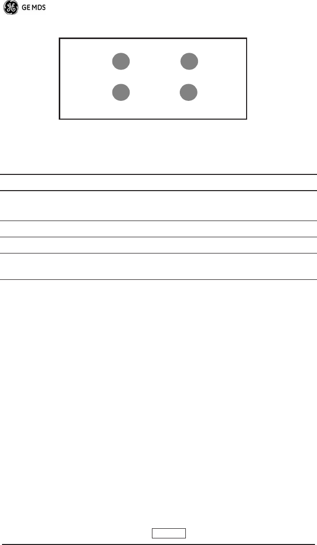
LED Indicators
The LED status indicators (Figure 9) are an important troubleshooting
aid and should be checked whenever a problem is suspected. Table 26
describes the function of each status LED on the front panel of the
radio.
44 TD220 Installation/Operation Guide 05-4819A01, Rev. 01
Invisible place holder
Figure 9. LED Indicators
Event Codes
When an alarm condition exists, the transceiver creates a code that can
be read on a connected terminal. These codes can be helpful in
resolving many system difficulties. Refer to Table 27 (Page 45) for a
definition of the event codes.
Checking for Alarms—STAT command
To check for alarms, connect a terminal to the radio’s DIAGNOSTICS
port. See SPECIFICATIONS on Page 47 for pinout information.
Enter STAT on the connected terminal. If no alarms exist, the message
NO ALARMS PRESENT appears on the display.
If an alarm does exist, a two-digit alarm code (00–31) is displayed and
the event is identified as a Major or Minor Alarm. A brief description
of the alarm is also given.
If more than one alarm exists, the word MORE appears on the screen.
To view additional alarms, press .
Table 26. LED Status Indicators
LED Name Description
PWR • Continuous—Power applied, no problems detected.
• Rapid flash (5 times-per-second)—Alarm indication.
TXD Data being transmitted over the air.
RXD Data being received over the air.
DCD When lit, indicates that a communication link is established
with the other station(s).
PWR
DCD
TXD
RXD
ENTER

05-4819A01, Rev. 01 TD220 Installation/Operation Guide 45
Major Alarms vs. Minor Alarms
Major Alarms—report serious conditions that generally indicate a
hardware failure, or other abnormal condition that will prevent (or
seriously hamper) further operation of the transceiver. Major alarms
generally indicate the need for factory repair. Contact your factory
representative for assistance.
Minor Alarms—report conditions that, under most circumstances will
not prevent transceiver operation. This includes out-of-tolerance con-
ditions, baud rate mismatches, etc. The cause of these alarms should
be investigated and corrected to prevent system failure.
Event Code Definitions
Table 27 contains a listing of event codes that may be reported by the
transceiver. The codes shown are a subset of a larger pool of codes
used for various GE MDS products. For this reason, the table does not
show a sequential listing of all code numbers. Only the codes appli-
cable to this product are shown.
Table 27. Event Codes
Event
Code
Event
Class Description
01 Major Improper software detected for this radio model.
04 Major The RF synthesizer is reporting an out-of-lock
condition.
08 Major The system is reporting that it has not been
calibrated. Factory calibration is required for proper
radio operation.
12 Major Receiver time-out. No data received within the
specified receiver time-out time.
13 Minor A Transmitter timeout was detected. The radio
stayed keyed longer than the duration specified by
the TOT command.
17 Minor A data parity fault has been detected on the
PAYLOAD port. This usually indicates a parity
setting mismatch between the radio and the
customer equipment.
18 Minor A data framing error has been detected on the
PAYLOAD port. This may indicate a baud rate
mismatch between the radio and the customer
equipment.

46 TD220 Installation/Operation Guide 05-4819A01, Rev. 01
Internal Spectrum Analyzer
The radio contains a built-in spectrum analyzer tool (Figure 10) that
can be displayed on a connected PC. The tool is helpful in diagnosing
interference problems on or near your channel frequency.
Access the spectrum analyzer by entering spectrum at the command
prompt. A display appears showing detected signals on your current
channel.
Optionally, you can specify a frequency at the command prompt to
view the surrounding spectrum of that frequency. To do this, enter
spectrum xxx.xx, where xxx.xx is the frequency in MHz.
As shown in Figure 10, the display creates a received signal strength
indication (RSSI) vs. frequency plot for the frequency and sur-
rounding signals. By analyzing the display, you can determine the
presence of other signals near the transceiver’s operating frequency.
This information can be helpful in troubleshooting interference prob-
lems.
26 Minor The DC input voltage is out-of-tolerance. If the
voltage is too far out of tolerance, operation may fail.
31 Minor The transceiver’s internal temperature is
approaching an out-of-tolerance condition. If the
temperature drifts outside of the recommended
operating range, system operation may fail.
Table 27. Event Codes (Cont’d)
Event
Code
Event
Class Description

05-4819A01, Rev. 01 TD220 Installation/Operation Guide 47
Invisible place holder
Figure 10. Internal Spectrum Analyzer Display
SPECIFICATIONS
GENERAL
Frequency Ranges*: 217-220 MHz
220-222 MHz
RECEIVER
Maximum Usable Sensitivity: –110 dBm at 1x10⁻⁶ BER (Preliminary)
Bandwidth: 12.5 kHz
TRANSMITTER
RF Carrier Power: 2 Watts (217-220 MHz)
25 Watts (220-222 MHz)
Duty Cycle: 25%
Output Impedance: 50 Ω
Channel Spacing: 6.25, 12.5 kHz
FCC Emission Designators:
12.5 kHz B/W: 11K0F1D

48 TD220 Installation/Operation Guide 05-4819A01, Rev. 01
:DATA CHARACTERISTICS
Payload Signaling Type: EIA/RS-485
Connector Type: DB-25 Female
Payload Data Rates: 300–115200 bps, asynchronous
Payload Data Latency: 10 ms maximum
DIAGNOSTICS INTERFACE
Signaling Standard: RS-232
PRIMARY POWER
Voltage: 13.8 Vdc Nominal (10.5 to 16 Vdc)
Negative-Ground Systems Only
TX Supply Current: 8 Amperes (Typical) @ 30 Watts Output
RX Supply Current: Operational—125 mA, Nominal
Fuse: 8-Ampere, internal
ENVIRONMENTAL
Humidity: 95% at 40 degrees C (104°F),
non-condensing
Temperature Range: –40 to 70 degrees C (–40°F to +158°F)
Weight: 1.0 kilograms

Installation Guide

GE MDS, LLC
Rochester, NY 14620
General Business: +1 585 242-9600
FAX: +1 585 242-9620
Web: www.GEmds.com
175 Science Parkway