GE MDS DS-TRM450 TRM450 Data Transceiver User Manual Manual revised
GE MDS LLC TRM450 Data Transceiver Manual revised
GE MDS >
Contents
- 1. Manual revised
- 2. User Manual
Manual revised
Integration Guide
410–470 MHz Data Transceivers
TRM 450 OEM Series
Microwave Data Systems Inc.
MDS 05-4121A01, Rev. A
DECEMBER 2003

MDS 05-4121A01, Rev. A TRM 450 Integration Guide iii
TABLE OF CONTENTS
1.0 INTRODUCTION .........................................................................7
1.1 Modem Speed versus Channel Bandwidth ......................................8
1.2 Frequency Coverage ........................................................................8
1.3 Radio Operating Modes ...................................................................8
Single Frequency (Simplex) Operation...............................................8
Switched-Carrier Operation (Half-Duplex)..........................................9
1.4 Applications ......................................................................................9
Point-to-Multipoint, Multiple Address Systems (MAS) ........................9
Point-to-Point System .......................................................................10
1.5 Model Number Codes ....................................................................11
2.0 INSTALLATION DESIGN ...........................................................12
2.1 Mounting the Transceiver ...............................................................13
2.2 Interface Requirements ..................................................................13
2.3 Antennas and Feedlines ................................................................14
Antennas ..........................................................................................14
Feedlines ..........................................................................................15
2.4 Primary Power (3.3 Vdc) ................................................................15
DC Supply Connection .....................................................................15
Shutdown Mode (Energy Conservation)...........................................16
2.5 Data Interface Connections ............................................................16
3.0 TRANSCEIVER CONFIGURATION AND DIAGNOSTIC
COMMANDS .............................................................................19
3.1 Error Messages ..............................................................................21
3.2 Initial Installation—Radio and Data Configuration ..........................21
4.0 TROUBLESHOOTING...............................................................23
5.0 TECHNICAL REFERENCE .......................................................24
5.1 TRM 450 Transceiver Specifications ..............................................24
5.2 Test and Evaluation Assembly .......................................................25
5.3 Vendors for Connectors ..................................................................28
5.4 dBm-Watts-Volts Conversion Chart ................................................30
6.0 GLOSSARY OF TERMS............................................................31
iv TRM 450 Integration Guide MDS 05-4121A01, Rev. A
Copyright Notice
This Installation and Operation Guide and all software described herein
are protected by
copyright: 2003 Microwave Data Systems Inc
. All
rights reserved.
Microwave Data Systems Inc. reserves its right to correct any errors and
omissions in this publication.
Antenna Installation Warning
1. All antenna installation and servicing is to be performed by
qualified technical personnel
only. When servicing the antenna, or
working at distances closer than those listed below,
ensure the
transmitter has been disabled.
2. Typically, the antenna connected to the transmitter is a directional
(high gain) antenna, fixed-mounted on the side or top of a building,
or on a tower. Depending upon the application and the gain of the
antenna, the total composite power could exceed 90 watts ERP. The
antenna location should be such that only qualified technical per-
sonnel can access it, and that under normal operating conditions no
other person can touch the antenna or approach within
2.3 meters
of
the antenna.
ISO 9001 Registration
Microwave Data Systems adheres to this internationally accepted
quality system standard.
MDS Quality Policy Statement
We, the employees of Microwave Data Systems Inc., are committed to
understanding and exceeding our customer’s needs and expectations.
• We appreciate our customer’s patronage. They are our business.
• We promise to serve them and anticipate their needs.
• We are committed to providing solutions that are cost effective,
innovative and reliable, with consistently high levels of quality.
• We are committed to the continuous improvement of all of our
systems and processes, to improve product quality and increase
customer satisfaction.
RF Exposure
Separation distances
required for FCC RF
Exposure compliance
Antenna Gain versus Recommended Safety Distance
(TRM 450 Series)
Antenna Gain (TRM 450 Series)
0–5 dBi 5–10 dBi 10–16.5 dBi
Minimum RF
Safety Distance
0.6 meter 1.06 meters 2.3 meters

MDS 05-4121A01, Rev. A TRM 450 Integration Guide v
ESD Notice
To prevent malfunction or damage to this product, which may be caused
by Electrostatic Discharge (ESD), the radio should be properly
grounded at the time of installation. In addition, the installer or main-
tainer should follow proper ESD precautions, such as touching a bare
metal object to dissipate body charge, prior to touching components or
connecting/disconnecting cables.
Manual Revision and Accuracy
While every reasonable effort has been made to ensure the accuracy of
this manual, product improvements may result in minor differences
between the manual and the product shipped to you. If you have addi-
tional questions or need an exact specification for a product, please con-
tact our Customer Service Team using the information at the back of this
guide. In addition, manual updates can often be found on the MDS Web
site at www.microwavedata.com.
FCC Part 15 Notice
This equipment has been tested and found to comply with the limits for
a Class B digital device, pursuant to Part 15 of the FCC Rules. These
limits are designed to provide reasonable protection against harmful
interference in a residential installation. This equipment generates, uses,
and can radiate radio frequency energy and, if not installed and used in
accordance with the instructions, may cause harmful interference to
radio communications. However, there is no guarantee that interference
will not occur in a particular installation. If this equipment does cause
harmful interference to radio or television reception, which can be deter-
mined by turning the equipment off and on, the user is encouraged to try
and correct the interference by one or more of the following measures:
• Reorient or locate the receiving antenna.
• Increase the separation between the equipment and receiver.
• Connect the equipment into an outlet on a circuit different from
that to which the receiver is connected.
• Consult the dealer or an experienced radio/TV technician for
help.
This Class B digital apparatus complies with Canadian ICES-003. Cet
appareil numérique de la classe B est conforme à la norme NMB-003 du
Canada.
Operation is subject to the following two conditions: (1) this device may
not cause interference, and (2) this device must accept any interference,
including interference that may cause undesired operation of the device.
Changes or modifications not expressly approved by the party respon-
sible for compliance could void the user's authority to operate the equip-
ment.

vi TRM 450 Integration Guide MDS 05-4121A01, Rev. A
MDS 05-4121A01, Rev. A TRM 450 Integration Guide 7
1.0 INTRODUCTION
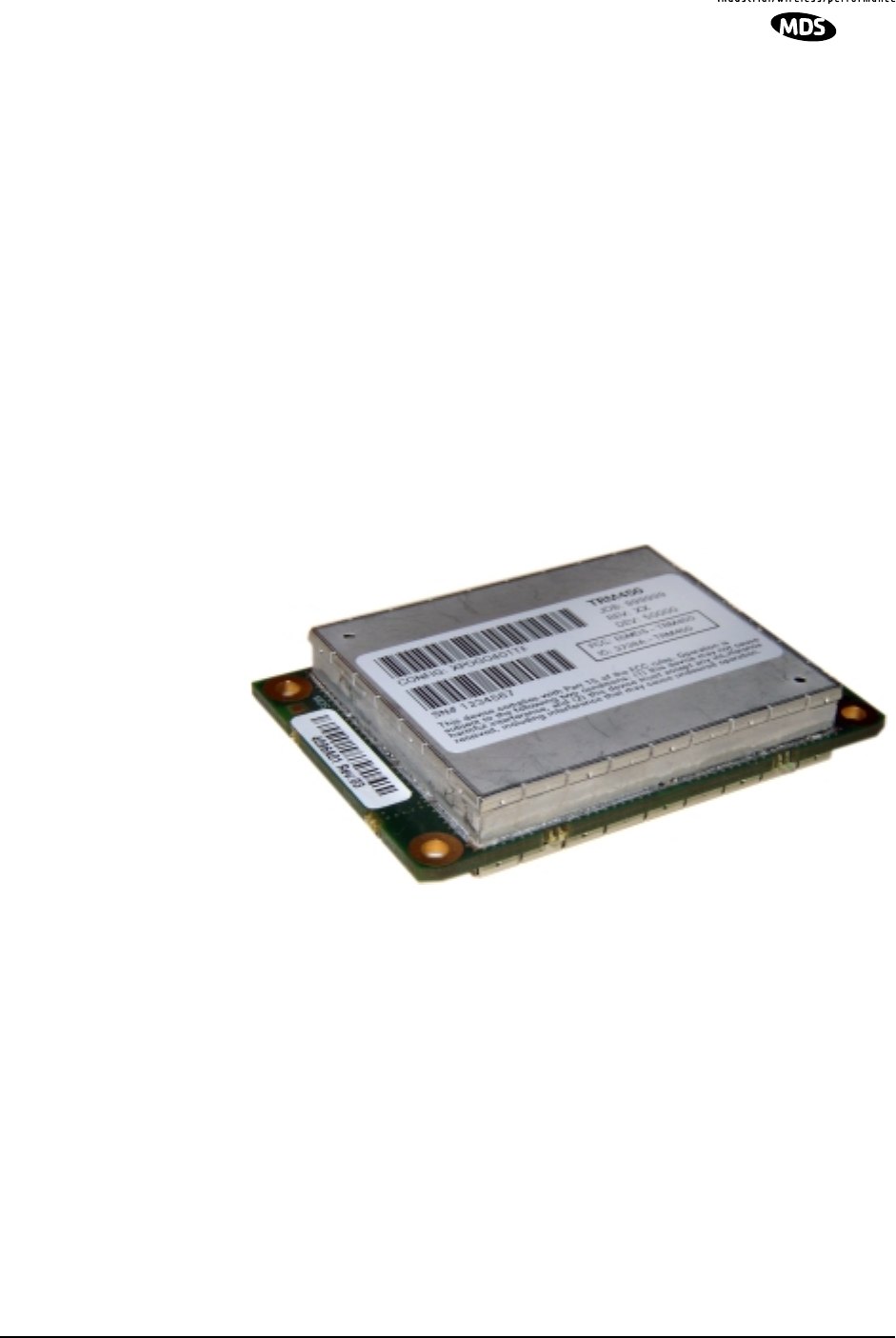
This guide presents installation and operating instructions for the
TRM 450 digital radio transceiver. The radio is a compact, modular
board well suited to user-designed customer integration with remote
terminal units (RTUs), programmable logic controllers (PLCs),
automatic banking machines, or similar equipment.
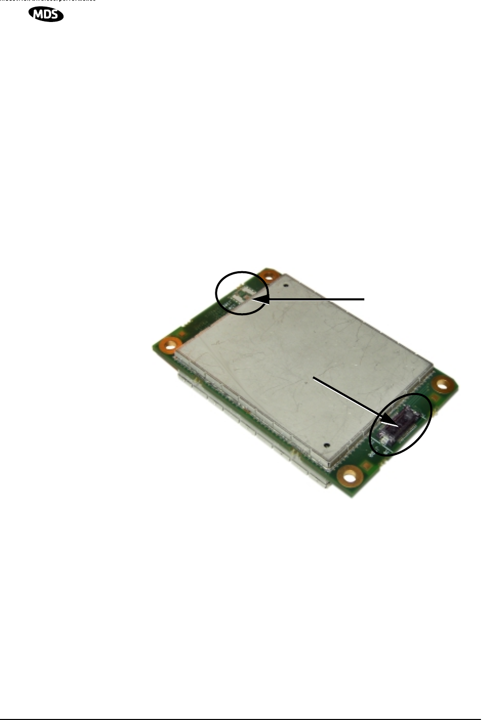
The transceiver (Figure 1) is a data telemetry radio designed to operate
in a point-to-multipoint environment, such as electric utility
Supervisory Control and Data Acquisition (SCADA) and distribution
automation, gas field automation, water and wastewater SCADA, and
on-line transaction processing applications. The radio employs
microprocessor control to provide highly reliable communications, even
under adverse conditions.
TRM 450 radios use Gaussian-mean shift keying (GMSK) modulation.
Invisible place holder
Figure 1. TRM 450 Data Transceiver

8 TRM 450 Integration Guide MDS 05-4121A01, Rev. A
1.1 Modem Speed versus Channel Bandwidth
The TRM 450 can be configured by the user to one-of-six arrangements
dependent on the permissible values of over-the-air data baud rate
(
BAUD
), Gaussian filtering (
BT
), and channel bandwidth (
BW
). The valid
configurations are:
The current configuration will be displayed by the
MODEM
command.
These parameters are independent of any other user-controllable
operating parameter.
1.2 Frequency Coverage
The TRM 450 series radios are available for operation in one of three the
frequency subbands between 410–470 MHz. The subbands are:
410–430 MHz, 430–450 MHz and 450–470 MHz. Any combination of
transmitter and receiver operating frequencies can be programmed
within the subband of the TRM 450, including a simplex (TX = RX)
pair.
NOTE:
Each of the three radio frequency ranges (subband) are factory
set and cannot be changed by the user.
1.3 Radio Operating Modes
Single Frequency (Simplex) Operation
Single frequency operation (also known as simplex) is a special case of
switched carrier operation. Single frequency operation is
automatically
selected whenever the transmit and receive frequencies are set to the
same value.
Table 1. Permissible Data Configurations
Baud (bps)
Receive
Bandwidth
(BW) BT
19200 25.0 kHz .3
16000 25.0 kHz .3
9600 25.0kHz .5
9600 12.5 kHz .3
8000 25 kHz .5
8000 12.5 kHz .3
4800 25.0 kHz .5
4800 12.5 kHz .5

MDS 05-4121A01, Rev. A TRM 450 Integration Guide 9
Switched-Carrier Operation (Half-Duplex)
Switched-carrier operation is a half-duplex mode where the master
station transmitter is keyed to send data and unkeyed to receive. MDS’
TRM 450 radios operate in switched-carrier mode and are keyed when
data is present.
NOTE:
TRM 450 radios do not support full-duplex operation (i.e.,
transmitting and receiving at the same time). For information
on other MDS products that provide this capability, contact
your sales representative.
1.4 Applications
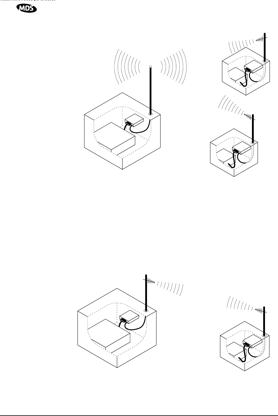
Point-to-Multipoint, Multiple Address Systems (MAS)
Point-to-multipoint (MAS) is the most common application of the
transceiver. It consists of a central master station and several associated
remote units as shown in Figure 2. An MAS network provides
communications between a central host computer and remote terminal
units (RTUs) or other data collection devices. The operation of the radio
system is “transparent” to the computer equipment. That is, the radio
system transports the data in its original form, making no changes to the
data format.
Often, the radio system is used to replace a network of remote monitors
currently linked to a central location by leased telephone lines. At the
central office of such a system, there is usually a large mainframe
computer and some means of switching between individual lines
coming from each remote monitor. In this type of system, there is a
modulator/demodulator (modem) at the main computer and at each
remote site, usually built into the remote monitor itself. Since the cost of
leasing a dedicated-pair telephone line is quite high, radio is frequently
used as an alternative communication medium.
10 TRM 450 Integration Guide MDS 05-4121A01, Rev. A
Invisible place holder
Figure 2. MAS Point-to-Multipoint Network
(Two remote stations shown—four or more are typically used)
Point-to-Point System
Where permitted, the transceiver may also be used in a point-to-point
arrangement.
A point-to-point system consists of just two radios—one
serving as a master and the other as a remote—as shown in Figure 3. It
provides a simplex or half-duplex communications link for the transfer
of data between two locations.
Invisible place holder
Figure 3. Typical Point-to-Point Link
radio
HOST
COMPUTER
MASTER
STATION
RTU
radio
REMOTE
RTU
radio
REMOTE
radio
HOST
COMPUTER
MASTER
STATION
RTU
radio
REMOTE

MDS 05-4121A01, Rev. A TRM 450 Integration Guide 11
1.5 Model Number Codes
The radio model number is printed on the PC board or on the radio
enclosure, and provides key information about how the radio was
configured when was shipped from the factory. See Figure 4 for an
explanation of the model number characters.
Invisible place holder
Figure 4. TRM 450 Model Number Codes
(As found on the serial number and identification label)
OPERATING MODE
T–TRANSCEIVER
R–RECEIVE ONLY
TRM 450
FREQUENCY BAND
1 410 – 430 MHZ
2 430 – 450 MHZ
3 450 – 470 MHZ
AGENCY
APPROVAL
E–ETSI
F–FCC
THIS INFORMATION IS
SUBJECT TO
CHANGE.
DO NOT USE FOR
PRODUCT ORDERING.
12 TRM 450 Integration Guide MDS 05-4121A01, Rev. A
2.0 INSTALLATION DESIGN
The TRM 450 is designed to be part of a larger electronic device or
system. It must be provided with adequate and stable primary power, a
complementary data interface and RF antenna system connections. An
appropriate antenna is the only external device that is needed.
Connections to the TRM 450 are through two connections: data and
power through an AVX Series 5046 fine-pitch (
DATA INTERFACE)
connector and RF signalling through PCB pads to a SMT PCB-to-PCB
pressure-contact coaxial connector. These connections require a stable
support for the TRM 450 module with positive pressure by the RF
connector on the RF I/O pads (J300/301). Figure 5 shows the external
connections for the transceiver.
Invisible place holder
Figure 5. External Connections to the Transceiver Board
(Bottom View of PCB)
The TRM 450 has all of its electronic circuitry enclosed in RF shields to
minimize interaction with nearby electronic products. The transceiver
module is compliant with FCC Part 90 and Part 15 in the 410–470 MHz
band. The transmitter can be set to produce 2 Watts of RF output.
Careful selection and/or design of the radio transmission line is
important to minimizing RFI to nearby electronic devices.
This unit must be provided with a good antenna system optimal
communication range and reliability. A secondary benefit is an
opportunity to run the system at the lowest possible power level, a lower
primary power consumption, and reduced chances of interference.
RF I/O PADS
DATA & POWER INTERFACE
CONNECTOR
(J300/301)
(J100)
MDS 05-4121A01, Rev. A TRM 450 Integration Guide 13
The data interface will support a variety of system designs. Use only the
required pins for the application.
Refer to the complete list of pin
functions in Table 4 on Page 17.
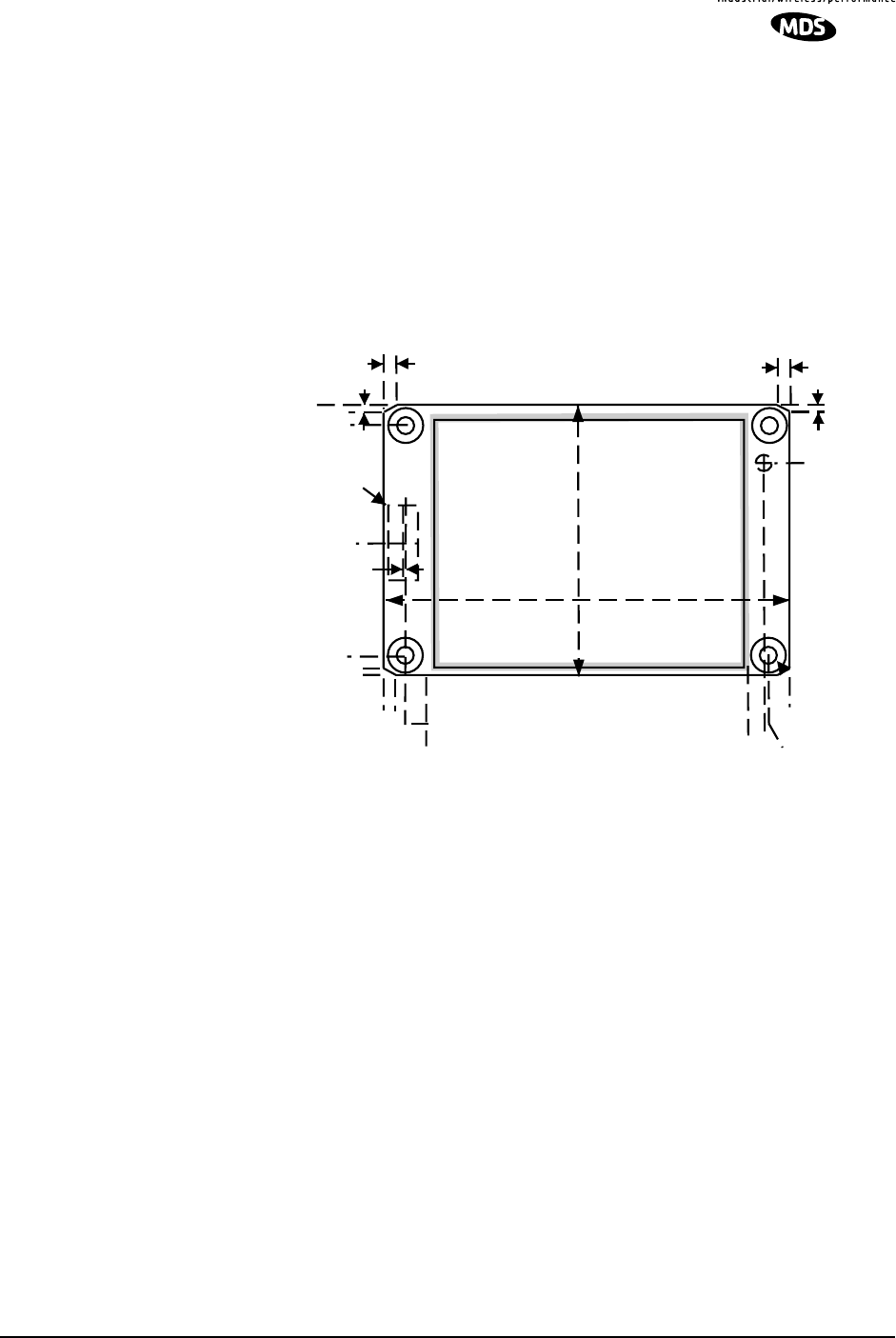
2.1 Mounting the Transceiver
Figure 6 shows the mounting dimensions of the transceiver PC board.
The board should be secured to the mounting surface using the holes
provided at each corner of the assembly. (Fasteners are not supplied.)
Invisible place holder
Figure 6. Transceiver Mounting Dimensions
2.2 Interface Requirements
It is highly beneficial to provide for electronic access to the TRM 450
module after it is installed in your product or system. This allows for
module configuration and control, frequency changes when needed,
antenna system optimization, and diagnostic activities.
In addition, it would be beneficial to provide field service personnel a
technique for directly monitoring the test and diagnostic indicators
produced by the unit to indicate the incoming radio signal strength
(RSSI), and the radio synthesizer’s unfiltered out-of-lock indicator.
.140
0.000
0.000
2.47
2.61
.140
1.555
1.695
2.750
1.835
2.33
.140
Data
Connector
.090" .090"
.050"
.050"
.010
.775
2.465
1.110
.090
.050
14 TRM 450 Integration Guide MDS 05-4121A01, Rev. A
Table 2 summarizes minimal recommended access requirements for
field setup and servicing of the TRM 450 radio transceiver. Other
interface signal functions may be of use to field service personnel or as
part of a diagnostic design for the whole user-defined package.
2.3 Antennas and Feedlines
Antennas
The transceiver can be used with a number of antennas. The exact style
depends on the physical size and layout of the radio system. Suitable
antennas are available from several manufacturers, including MDS.
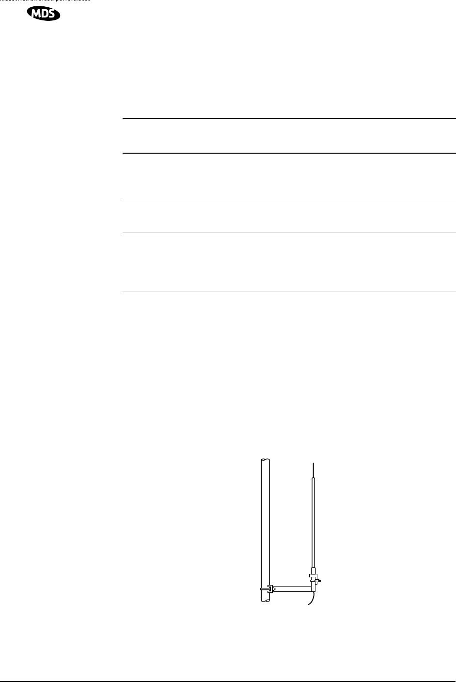
At master stations, omni-directional antennas (Figure 7) are typically
used to provide equal coverage to all remote sites in the network.
Invisible place holder
Figure 7. Typical Omni-directional Antenna for Master Stations
(Shown mounted to mast)
Table 2. Configuration and Evaluation Signals
Function
Data
Interface
Pin Signal Type
)
Description
Enable Configuration 11 Low = Enabled Enables terminal
interaction with module.
Disables payload
throughput.
Received (RF) Signal
Strength Signal
Indicator—RSSI
12 Analog
0–3 Vdc Aid to aiming antenna
system and determining
presence of radio signals
Synthesizer Lock 2 H = Locked
L = Out-of-Lock
Unprocessed indicator of
state of transceiver’s
frequency synthesizer.
Signal may contain
inconsequential transients

MDS 05-4121A01, Rev. A TRM 450 Integration Guide 15
At remote sites, a directional Yagi (Figure 8) or corner reflector antenna
is generally recommended to minimize interference to and from other
users.
Invisible place holder
Figure 8. Typical Yagi Antenna for Remote Sites
Feedlines
The selection of antenna feedline is very important. Poor quality cables
should be avoided as they result in power losses that may reduce the
range and reliability of the radio system.
Table 3 shows the losses that occur when using various lengths and
types of cable at 400 MHz. Regardless of the type of cable used, it
should be kept as short as possible to minimize signal loss.
2.4 Primary Power (3.3 Vdc)
DC Supply Connection
The transceiver can be operated from any well-filtered 3.3 Vdc power
source through the
DATA INTERFACE
connector. The power supply must
be capable of providing at least 1.5 Amperes and provide current
limiting even if you intend to operate the radio at low power (0.5 Watts).
NOTE: The radio is designed for use in
negative ground systems only.
There is no fuse or reverse polarity protection provided on the
TRM 450 PCB assembly.
Table 3. Length vs. Loss in Coaxial Cables at 400 MHz
Cable Type 10 Feet
(3.05 Meters) 50 Feet
(15.24 Meters) 100 Feet
(30.48 Meters) 500 Feet
(152.4 Meters)
RG-8A/U 0.51dB 2.53 dB 5.07 dB 25.35 dB
1/2 inch HELIAX 0.12 dB 0.76 dB 1.51 dB 7.55 dB
7/8 inch HELIAX 0.08 dB 0.42 dB 0.83 dB 4.15 dB
1-1/4 inch HELIAX 0.06 dB 0.31 dB 0.62 dB 3.10 dB
1-5/8 inch HELIAX 0.05 dB 0.26 dB 0.52 dB 2.60 dB
CAUTION
POSSIBLE
EQUIPMENT
DAMAGE

16 TRM 450 Integration Guide MDS 05-4121A01, Rev. A
The positive (+) DC power must be provided through pins 23, 24, 25,
26, 27,and 28. The data signal and DC power current return (–) should
be connected to pins 1, 7, 9, 19, 20, 21, 22, and 30. (See Figure 5 on
Page 12 for details.)
Shutdown Mode (Energy Conservation)
In some installations, such as at solar-powered sites, it may be necessary
to keep the transceiver’s power consumption to an absolute minimum.
This can be accomplished by configuring the data device (RTU, PLC,
etc.) to ground the DATA INTERFACE connector Pin 29 to power-down
the radio until communication to other devices is needed. All radio and
microprocessor activity is disabled when the radio is in the shutdown
mode. When the ground is removed from Pin 29, the radio is ready to
operate within 75 milliseconds.
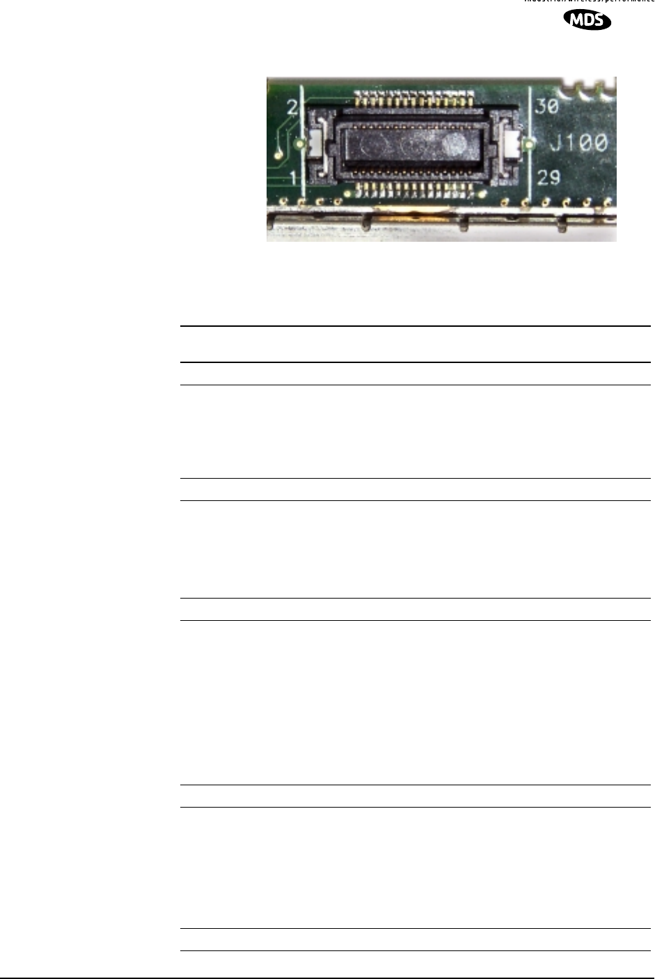
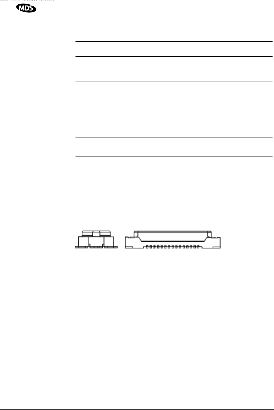
2.5 Data Interface Connections
The transceiver’s DATA INTERFACE connector is configured as a DCE
(modem) and supports over-the-air asynchronous data rates up to
19200 bps. (4800, 8000, 9600, 16000, and 19200 bps) The DATA
INTERFACE is normally connected to a device/circuit with a TTL
interface. Refer to Figure 9 and Table 4 for a detailed description of
each pin on the DATA INTERFACE connector.
Some pins on the DATA INTERFACE connector are used for factory
testing. Use only the required pins for the application. Damage may
result if improper connections are made.
CAUTION
USE ONLY
REQUIRED PINS
MDS 05-4121A01, Rev. A TRM 450 Integration Guide 17
Invisible place holder
Figure 9. Data Interface Connector
(As viewed from above)
Table 4. DATA INTERFACE Connector Pinouts
Pin
Number Input/
Output Pin Description
1 IN/OUT Ground
2 OUT RF synthesizer lock detect signal
• High = locked (Radio ready for service)
• Low = Out-of-lock (Radio disabled)
• Raw / “unfiltered”
3INTX Data—Transmit Data (payload) in normal operation
4 OUT CD—Carrier Detect
• Low whenever RSSI exceeds the programmed CDR
threshold.
• Detects RF activity on the radio channel regarless of the
signals modulation type or data protocol.
5 IN/OUT Ground (Power and signal)
6 OUT RX Clock—Always applicable when receiving
• Goes from low to high at the center of each RX Data bit
(receive mode)
• Provided when transmitting if “CLK RX” is programmed
• Goes from low to high to request each new TXD bit
• Continuously high when transceiver is in Configuration
Mode (J100, Pin 11 = Low)
7 IN/OUT Ground (Power and signal)
8 OUT TX Clock—Transmit Data Clock
• Only applicable when “CLK TX” is programmed and TX
ON is asserted
• Clock goes from low to high to request each new TXD bit
• Continuously high when in Configuration Mode (J100,
Pin 11 = Low), or when “CLK RX” is selected
9 IN/OUT Ground (Power and signal)

18 TRM 450 Integration Guide MDS 05-4121A01, Rev. A
10 Do not connect—Reserved for factory use only.
11 IN CONFIG—Configure Radio
• High puts radio in normal payload mode to receive or
transmit data at the programmed rate
• Low puts radio in setup mode to communicate with the
processor at 38.4 kbps asynchronously
12 OUT RSSI—Receive Signal Strength Indicator
• Analog voltage between 0 and 3 Vdc proportional to
signal strength on the channel
13 IN TX ON—Request to key radio transmitter
• High puts radio in transmit mode
• Low puts radio in receive mode
14 OUT RX Data—Receive Data
• Receive data (off-the-air) in normal operation
• Control data from the processor in setup mode
15 OUT RX Audio—Filtered receive audio
• For test purposes only
16 Do not connect—Reserved for factory use only.
17 Not used – Do not connect
18 Vcc—Regulated +3.3 Vdc power for the transceiver
19 IN/OUT Ground (Power and signal)
20 IN/OUT Ground (Power and signal)
21 IN/OUT Ground (Power and signal)
22 IN/OUT Ground (Power and signal)
23 IN Vcc—Regulated +3.3 Vdc power for the transceiver
24 IN Vcc—Regulated +3.3 Vdc power for the transceiver
25 IN Vcc—Regulated +3.3 Vdc power for the transceiver
26 IN Vcc—Regulated +3.3 Vdc power for the transceiver
27 IN Vcc—Regulated +3.3 Vdc power for the transceiver
28 IN Vcc—Regulated +3.3 Vdc power for the transceiver
29 IN Shutdown Mode
• Low puts radio in low-power shutdown
• High or open allows normal operation
30 IN/OUT Ground (Power and signal)
Table 4. DATA INTERFACE Connector Pinouts (Continued)
Pin
Number Input/
Output Pin Description

MDS 05-4121A01, Rev. A TRM 450 Integration Guide 19
3.0 TRANSCEIVER CONFIGURATION
AND DIAGNOSTIC COMMANDS
The transceiver’s configuration and diagnostics are performed through
the radio’s DATA INTERFACE connector through a “dumb” data terminal
interface—either a personal computer or dedicated terminal. An
EIA/RS-232 to TTL converter circuit may be required depending on
your installation design. Configuration and diagnostic activities may be
performed with the TRM 450 removed from the user equipment or as an
installed module in your design.
If you choose to setup the TRM 450 before its final installation, you may
find using MDS’ TRM 450 Test and Evaluation Assembly a convenient
tool. (See Test and Evaluation Assembly on Page 25 for more detail.)
Table 5 lists each command entry and a brief description of its purpose.
Programmable information is shown in brackets [ ] following the
command name.
To enter a command, type the command, followed by an
keystroke. For programming commands, the command is followed by
and the appropriate information or values, then .
Table 5. Command Summary
Command Function
MODEM MODEM—Data Configuration
Response indicates:
Payload data rate (BAUD)
+ Gaussian Bandwidth x Data Rate (BT)
+ Channel Spacing (BW)
For example: 9.6Kbps BT=.5 25KHz.
NOTE: Provides only an informational display. The
command cannot be used to configure the radio.
TX [xxx.xxxxx] Transmit RF Channel Frequency
• The frequency must be within the operating range for the
unit.
• Up to 5 digits can be entered after the decimal point.
Trailing zeros are not required.
• Frequencies can be in either 5 or 6.25 kHz increments.
BAUD [xxxxx] “Over-the-Air” Modem Speed
• Options: 4800, 8000, 9600, 16000 and 19200
• For synchronous payload data through the DATA
INTERFACE port (J100)
NOTES:
• Must complement BT and BW values.
(See Table 1 on Page 8.)
• Data rate for serial data (RXD/TXD) diagnostic/command
interface is always 38400
ENTER
SPACE ENTER

20 TRM 450 Integration Guide MDS 05-4121A01, Rev. A
BT [.x] Relative TX Bandwidth
• Valid options are .3 and .5
• Leading zero (Ø) not permitted
NOTE: Must complement BAUD and BW values.
(See Table 1 on Page 8.)
BW [xx.x] Channel Bandwidth
• Options: 25 and 12.5 kHz
NOTE: Must complement BT and BW values.
(See Table 1 on Page 8.)
CLK [xx] Clock Output Pin
Selects which serial clock line to use for transmit operation.
• Options: TX and RX
• TX = Pin 8/TXC
• RX = Pin 6/RXC
CDR [–xxx] Receiver Carrier Detect Threshold
• Inhibits the receiver from processing an incoming signal
unless it is above the setting’s level.
• Range: –50 to –120
NOTE: A setting of -120 removes any limitation on signal
detection.
CDT [–xxx] Transmit Carrier Detect Threshold
Inhibits the transmitter from operating in the presence of a
strong on-channel signal until the signal level is below the
setting level.
• Range: –50 to –120
NOTES:
• –50 will effectively allow transmissions anytime
• –120 will effectively prohibit transmissions.
• Minus sign (–) required for data entry
PWR [x] RF Power Output Level
Options:
H = High Power (2 Watts)
L = Low Power (0.5 Watts)
SCRAM [xxx] Data Scrambler/Descrambler ON/OFF
Options: ON or OFF
SREV [xxx] Software Revision of installed firmware
SER Serial Number of the radio
RSSI Received Signal Strength Indictor
• Displays the current received RF signal level
• One measurement per request by command
• Reading is accurate to within 3 dB from –100 dBm to –60
dBm
NOTE: A continuous RSSI signal available during receive
state on the DATA INTERFACE connector (J100-Pin12).
Table 5. Command Summary (Continued)
Command Function

MDS 05-4121A01, Rev. A TRM 450 Integration Guide 21
3.1 Error Messages
Listed below are some possible error messages that may be encountered
when using the terminal interface:
UNKNOWN COMMAND—The command was not recognized. Refer to the
command description for command usage information.
INCORRECT ENTRY—The command format or its associated values were
not valid. Refer to the command description for command usage
information.
COMMAND FAILED—The command was unable to successfully complete.
This may indicate an internal software problem.
NOT PROGRAMMED—Software was unable to program the internal radio
memory or the requested item was not programmed. This is a serious
internal radio error. Contact MDS for assistance.
TEXT TOO LONG—Response to OWN command when too many characters
have been entered. Refer to the command description for command
usage information.
NOT AVAILABLE—The entered command or parameter was valid, but it
referred to a currently unavailable choice. Refer to the command
description for command usage information.
3.2 Initial Installation—Radio and Data
OWN [xxx] Owner’s Message
Displays an optional owner message
• Enter OWN to display current entry.
• Enter OWN followed by up to 30 characters to program.
KEY Transmitter Carrier Key
• Test command for technicians to key the radio with a
unmodulated carrier.
• Use DKEY command to cease transmission
NOTES:
• Use only for test purposes.
• No time-out timer on this function.
DKEY Unkey Transmitter Test Carrier
Table 5. Command Summary (Continued)
Command Function

22 TRM 450 Integration Guide MDS 05-4121A01, Rev. A
Configuration
Below are the basic steps for setting up of the transceiver once it is
installed in the user’s product. In many cases, these steps alone are
sufficient to complete the installation. This procedure assumes the
TRM 450 has been installed in your system/product and suitable
connections have been provided for a terminal interface and antenna.
3. Install the antenna and antenna feedline for the station. Preset
directional antennas in the desired direction of transmission and
reception.
4. Connect a terminal (computer with emulations software) to the
TRM 450 through the user’s product interface. (async @ 38400
w/8N1)
5. Enable the configuration mode for the TRM 450 radio. (Ground
Pin 11 of the radio transceiver’s DATA INTERFACE.) DIAGNOSTICS
OPEN will appear on the terminal screen terminal once diagnostics
communication with the radio is established.
6. Review the existing essential TRM 450 configuration parameters
through a series of terminal commands.
•MODEM—Data Configuration
Response indicates:
Payload data rate (BAUD)
Gaussian Bandwidth x Data Rate (BT)
Channel Spacing (BW)
For example: 9.6Kbps BT=.5 25KHz.
•PWR—RF Power Output
Responses: H = 2 Watts, L = 0.5 Watts
7. Check and set the radio transmit and receive frequencies.
NOTE: The operating frequencies are typically not set at the factory.
Determine the transmit and receive frequencies to be used, and
follow the steps below to program them. The TRM 450 must
be programmed for the frequencies for which you hold a valid
license and be within the radio’s operating subband. (See
Figure 4 on Page 11 for guidance in identifying the radio’s
operating band.)
a. Set the transmit frequency with the TX xxx.xxxxx command.
Press after the command.
ENTER

MDS 05-4121A01, Rev. A TRM 450 Integration Guide 23
b. Set the receive frequency with the RX xxx.xxxxx command.
Press after the command.
c. After programming any parameter, PROGRAMMED OK will be
displayed to indicate a successful entry.
8. Review and reprogram any other parameters as necessary to
complement your system requirements. (See Table 5 on Page 19 for
a list of all user commands.)
9. Optimize the antenna installation by measuring the received signal
strength of the other station with which this station will be
communicating. Monitor the TRM 450’s RSSI level. Rotate the
station antenna until the signal is the strongest. The less negative the
value, the stronger the incoming radio signal.
The received signal should be at least –90 dBm. This value will
provide a safety margin (fade margin) to prevent loss of
communications through signal reduction (fading) caused by
weather conditions, changes in station location if mobile, or other
obstructions temporarily positioned between communicating
TRM 450 stations.
10. Disconnect the terminal interface and the ground from Pin 11 from
the DATA INTERFACE connector.
11. Connect the data equipment to the transceiver’s DATA INTERFACE
connector and test for normal operation.
4.0 TROUBLESHOOTING
Successful troubleshooting of the radio system is not difficult, but it
requires a logical approach. It is best to begin troubleshooting at the
master station, as the rest of the system depends on the master for
polling commands. If the master station has problems, the operation of
the entire network can be compromised.
It is good practice to start by checking the simple things. For proper
operation, all radios in the network must meet these basic requirements:
•Adequate and stable primary power.
•Secure connections (RF, data, and power).
•An efficient and properly aligned antenna system with a good
received signal strength (at least –90 dBm). It is possible for a
system to operate with weaker signals, but reliability may be
degraded.
ENTER

24 TRM 450 Integration Guide MDS 05-4121A01, Rev. A
•Proper programming of the transceiver’s operating parameters
(see Section 3.0, TRANSCEIVER CONFIGURATION AND
DIAGNOSTIC COMMANDS).
•The correct interface between the transceiver and the connected
data equipment (correct cable wiring, proper data format, timing,
etc.).
5.0 TECHNICAL REFERENCE
5.1 TRM 450 Transceiver Specifications
RADIO TYPE
Synthesized, half duplex, 6.25 and 5.0 kHz channel spacing, split frequency, or simplex
ENVIRONMENTAL
Temperature Range: –30 to +60 degrees C
Humidity: 0 to 95% at 40 degrees C
Board Dimensions: 2.75″ W x 0.4″ H x 1.75″ D
7.0 cm W x 1.10 cm H x 4.4 cm D
Weight: x.x oz. (x.x kg)
Enclosure: None. Open-frame PCB with digital/RF circuit
shield
TRANSMITTER
Frequency Range: 410 – 430 MHz
430 – 450 MHz
450 – 470 MHz
Frequency Increments: 6.25 and 5.0 kHz
Frequency Stability: 1.5 ppm, –30 to +60 degrees C
Channel Spacing: 6.25 and 5.0 kHz
Modulation Type: GMSK (Gaussian-mean Shift Keying)
Carrier Power: 0.5 W, 2 W programmable
(+27 DBM, +33 dBm)
Duty Cycle: 50%
Output Impedance: 50 ohms
RF Connection: Pads for SMT IMP 3 mm RF connector
Spurious and Harmonics: –65 dBc
Transmitter Keying: On reception of data
Key-up Time: 2 ms
Data Rate Over-the-Air : 4800, 8000, 9600, 16000, and 19200 bps
(Rate user-selectable via BAUD command)
RECEIVER
Type: Double conversion superheterodyne
(45 MHz IF)
Frequency Range: 410 – 430 MHz
430 – 450 MHz
450 – 470 MHz
Frequency Increments: 6.25 kHz

MDS 05-4121A01, Rev. A TRM 450 Integration Guide 25
Frequency Stability: 1.5 ppm, –30 to +60 degrees C
Spurious and Image Rejection: –70 dB
Sensitivity: 12 dB SINAD @ –119 dBm @ 4800 bps
12 dB SINAD @ –116 dBm @ 19200 bps
Intermodulation Rejection: –70 dB minimum
Selectivity: 60 dB typical at adjacent channel (EIA)
Bandwidth: 12.5 kHz
DATA INTERFACE
Connector: AVX fine-pitch 5046 series
Signaling: TTL
Data Rate—Diagnostics: 38400 bps asynchronous
Data Rate—Payload: 38400 bps synchronous
Flow-Control: Synchronous serial with clock supplied by the radio
in bursts of 8 bits (when the radio is ready)
Data Latency: < 20 ms typical
PRIMARY POWER
Voltage: 3.3 Vdc (3.2–3.6) via Data Interface connector
RX Current at 3.3 Vdc (typical): 112 mA
TX Current at 3.3 Vdc (typical): 1.8 A @ high power (2W)
750 mA @ low power (0.5W)
Current Limit/Polarity Protection: External; User-provided
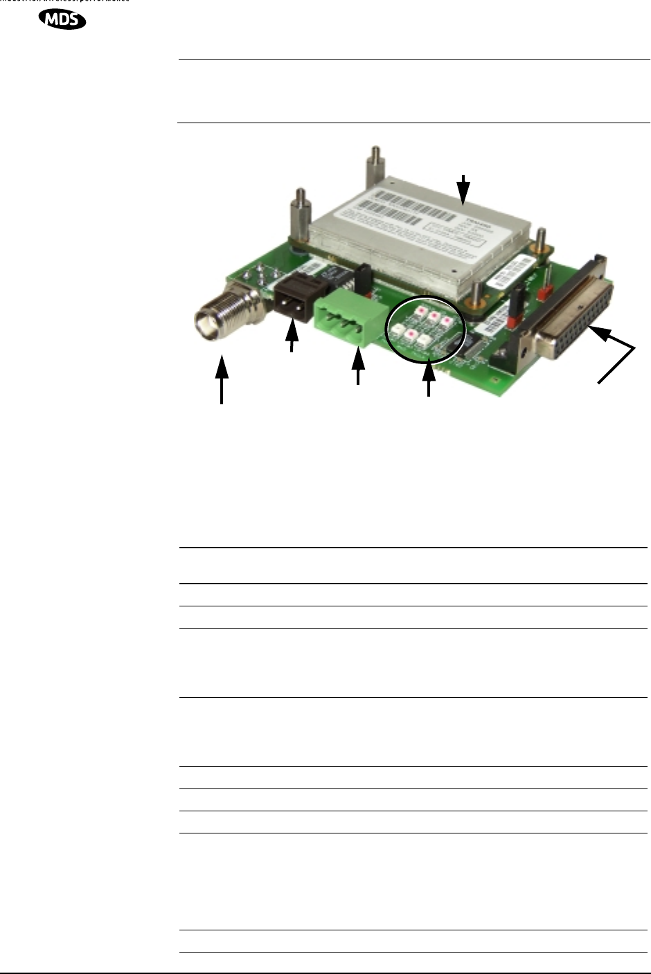
5.2 Test and Evaluation Assembly
A PCB assembly (03-6053A02) is available from MDS to facilitate
bench testing, programming and evaluation of the TRM 450 transceiver
module. This module features:
•Mounting Posts for aligning and securing TRM 450 module
•3.3 Vdc Power Input Receptacle
•6–12 Vdc Power Input Receptacle
•DB-25 Data Interface (Female)
providing EIA/RS-232 to TTL signalling conversion
•Radio Configuration Mode Enable (Manual Jumper)
•Activity LEDs:
TXD
RXD
TX CLOCK
RX CLOCK
CARRIER DETECT
TEST (Reserved)
•Antenna Connector–RF I/O (TNC)
•Receiver Analog Output through DB-25 interface connector
26 TRM 450 Integration Guide MDS 05-4121A01, Rev. A
NOTE: The Test and Evaluation Assembly is not intended for service
in a permanent installation in a user-designed product or
system.
Invisible place holder
Figure 10. Test and Evaluation PCB Assembly
(With TRM 450 module installed and retainers on RF connector end.)
3.3 VDC IN
TRM
450 MODULE
6–12 VDC IN
EIA/RS-232 I/O
TEST ANTENNA/LOAD DB-25(F)
ACTIVITY
LEDS
Table 6. DB-25 Interface Connector Pinouts
Test and Evaluation PCB
Pin
Number Input/
Output Pin Description
1 IN/OUT
Ground
(Signal)
2IN
TX Data—Transmit Data
(payload) in normal operation
3 OUT
RX Data—Receive Data
•
Receive data (off-the-air) in normal operation
•
Control data from the processor in setup mode
4 OUT
TX ON—Request to key radio transmitter
•
High puts radio in transmit mode
•
Low puts radio in receive mode
5
6 No connection
7 IN/OUT
Ground
(Signal)
8 OUT CD—Carrier Detect
•
Low whenever RSSI exceeds the programmed CDR
threshold.
•
Detects RF activity on the radio channel without
consideration for the signals modulation type or protocol.
9 Factory Test– Do not connect

MDS 05-4121A01, Rev. A TRM 450 Integration Guide 27
10 No connection
11 OUT
RX Audio—Filtered receive audio
•
For test purposes only
•
Also available through J109 (Pin 1 – Out, Pin 2 – GND)
12 IN
Shutdown
•
Low = Radio powered down (off-line)
13 OUT
RF synthesizer lock detect signal
•
High = locked (Radio ready for service)
•
Low = Out-of-lock (Radio disabled)
•
Raw / “unfiltered”
14 No connection
15 OUT
TX Clock—Transmit Data Clock
•
Only applicable when “
CLK TX
” is programmed and TX
ON is asserted
•
Clock goes from low to high to request each new TXD bit
•
Continuously high when in Configuration Mode (J100,
Pin 11 = Low), or when “
CLK RX
” is selected
16 No connection
17 OUT
RX Clock—
Always applicable when receiving
•
Goes from low to high at the center of each RX Data bit
(receive mode)
•
Provided when transmitting if “
CLK RX
” is programmed
•
Goes from low to high to request each new TXD bit
•
Continuously high when transceiver is in Configuration
Mode (J100, Pin 11 = Low)
18 Do not connect—Reserved for factory use only.
19 No connection
20 No connection
Table 6. DB-25 Interface Connector Pinouts
Test and Evaluation PCB (Continued)
Pin
Number Input/
Output Pin Description
28 TRM 450 Integration Guide MDS 05-4121A01, Rev. A
5.3 Vendors for Connectors
The following are vendors of interface connectors that may be used on
customer-designed interfaces or equipment connected to the TRM 450.
These are not the only sources of these devices nor does this listing
represent an endorsement by Microwave Data Systems.
Data Interface Connector
30-Pin PCB SMT Receptacle, J100
MDS: 73-3463A12
AVX: 14-5046-030-630-829
30-Pin PCB SMT Plug, Mates with J100
MDS: 73-3463A13
AVX: 24-5046-030-600-829
Vendor:
AVX Corporation
Web: www.AVXcorp.com
21 OUT RSSI—Receive Signal Strength Indicator
• Analog voltage between 0 and 3 Vdc proportional to
signal strength on the channel
22 No connection
23 IN CONFIG—Configure Radio
• High (unterminated) puts radio in normal payload mode
to receive or transmit data at the programmed rate
• Low (Ground/J108 Jumpered) puts radio in setup mode
to communicate with the processor at 38.4 kbps
asynchronously
24 No connection
25 No connection
Table 6. DB-25 Interface Connector Pinouts
Test and Evaluation PCB (Continued)
Pin
Number Input/
Output Pin Description

MDS 05-4121A01, Rev. A TRM 450 Integration Guide 29
RF Coaxial Connector
PCB SMT Connector
Mounted on user’s mating PCB to make contact with TRM 450 RF
pads J300/301
MDS: 73-1022A53
Radiall: R107.064.020
Vendor:
Radiall SA
101 Rue Philibert Hoffmann
93116 Rosny Sous Bois
France
Tel: + 33 1 49 35 35 35
FAX: + 33 1 49 35 35 14
Web: www. Radiall.com

30 TRM 450 Integration Guide MDS 05-4121A01, Rev. A
5.4 dBm-Watts-Volts Conversion Chart
Table 7 is provided as a convenience for determining the equivalent
wattage or voltage of an RF power expressed in dBm.
Table 7. dBm-Watts-Volts Conversion—for 50 Ohm Systems
dBm V Po
+53 100.0 200W
+50 70.7 100W
+49 64.0 80W
+48 58.0 64W
+47 50.0 50W
+46 44.5 40W
+45 40.0 32W
+44 32.5 25W
+43 32.0 20W
+42 28.0 16W
+41 26.2 12.5W
+40 22.5 10W
+39 20.0 8W
+38 18.0 6.4W
+37 16.0 5W
+36 14.1 4W
+35 12.5 3.2W
+34 11.5 2.5W
+33 10.0 2W
+32 9.0 1.6W
+31 8.0 1.25W
+30 7.10 1.0W
+29 6.40 800mW
+28 5.80 640mW
+27 5.00 500mW
+26 4.45 400mW
+25 4.00 320mW
+24 3.55 250mW
+23 3.20 200mW
+22 2.80 160mW
+21 2.52 125mW
+20 2.25 100mW
+19 2.00 80mW
+18 1.80 64mW
+17 1.60 50mW
+16 1.41 40mW
+15 1.25 32mW
+14 1.15 25mW
+13 1.00 20mW
+12 .90 16mW
+11 .80 12.5mW
+10 .71 10mW
+9 .64 8mW
+8 .58 6.4mW
+7 .500 5mW
+6 .445 4mW
+5 .400 3.2mW
+4 .355 2.5mW
+3 .320 2.0mW
+2 .280 1.6mW
+1 .252 1.25mW
dBm V Po
0 .225 1.0mW
-1 .200 .80mW
-2 .180 .64mW
-3 .160 .50mW
-4 .141 .40mW
-5 .125 .32mW
-6 .115 .25mW
-7 .100 .20mW
-8 .090 .16mW
-9 .080 .125mW
-10 .071 .10mW
-11 .064
-12 .058
-13 .050
-14 .045
-15 .040
-16 .0355
dBm mV Po
-17 31.5
-18 28.5
-19 25.1
-20 22.5 .01mW
-21 20.0
-22 17.9
-23 15.9
-24 14.1
-25 12.8
-26 11.5
-27 10.0
-28 8.9
-29 8.0
-30 7.1 .001mW
-31 6.25
-32 5.8
-33 5.0
-34 4.5
-35 4.0
-36 3.5
-37 3.2
-38 2.85
-39 2.5
-40 2.25 .1µW
-41 2.0
-42 1.8
-43 1.6
-44 1.4
-45 1.25
-46 1.18
-47 1.00
-48 0.90
dBm mV Po
-49 0.80
-50 0.71 .01µW
-51 0.64
-52 0.57
-53 0.50
-54 0.45
-55 0.40
-56 0.351
-57 0.32
-58 0.286
-59 0.251
-60 0.225 .001µW
-61 0.200
-62 0.180
-63 0.160
-64 0.141
dBm µV Po
-65 128
-66 115
-67 100
-68 90
-69 80
-70 71 .1nW
-71 65
-72 58
-73 50
-74 45
-75 40
-76 35
-77 32
-78 29
-79 25
-80 22.5 .01nW
-81 20.0
-82 18.0
-83 16.0
-84 11.1
-85 12.9
-86 11.5
-87 10.0
-88 9.0
-89 8.0
-90 7.1 .001nW
-91 6.1
-92 5.75
-93 5.0
-94 4.5
-95 4.0
-96 3.51
-97 3.2
dBm µV Po
-98 2.9
-99 2.51
-100 2.25 .1pW
-101 2.0
-102 1.8
-103 1.6
-104 1.41
-105 1.27
-106 1.18
dBm nV Po
-107 1000
-108 900
-109 800
-110 710 .01pW
-111 640
-112 580
-113 500
-114 450
-115 400
-116 355
-117 325
-118 285
-119 251
-120 225 .001pW
-121 200
-122 180
-123 160
-124 141
-125 128
-126 117
-127 100
-128 90
-129 80 .1ƒW
-130 71
-131 61
-132 58
-133 50
-134 45
-135 40
-136 35
-137 33
-138 29
-139 25
-140 23 .01ƒW

MDS 05-4121A01, Rev. A TRM 450 Integration Guide 31
6.0 GLOSSARY OF TERMS
If you are new to digital radio systems, some of the terms used in this
guide may be unfamiliar. The following glossary explains many of these
terms and is helpful in understanding the operation of the transceiver.
Antenna System Gain—A figure, normally expressed in dB,
representing the power increase resulting from the use of a gain-type
antenna. System losses (from the feedline and coaxial connectors, for
example) are subtracted from this figure to calculate the total antenna
system gain.
Bit—The smallest unit of digital data, often represented by a one or a
zero. Eight bits (plus start, stop, and parity bits) usually comprise a byte.
Bits-per-second—See BPS.
BPS—Bits-per-second. A measure of the information transfer rate of
digital data across a communication channel.
Byte—A string of digital data usually made up of eight data bits and
start, stop and parity bits.
Data Circuit-terminating Equipment—See DCE.
Data Communications Equipment—See DCE.
Data Terminal Equipment—See DTE.
dBi—Decibels referenced to an “ideal” isotropic radiator in free space.
Frequently used to express antenna gain.
dBm—Decibels referenced to one milliwatt. An absolute unit used to
measure signal power, as in transmitter power output, or received signal
strength.
DCE—Data Circuit-terminating Equipment (or Data Communications
Equipment). In data communications terminology, this is the “modem”
side of a computer-to-modem connection. The MDS TRM 450 is a DCE
device.
Decibel (dB)—A measure computed from the ratio between two signal
levels. Frequently used to express the gain (or loss) of a system.
DTE—Data Terminal Equipment. A device that provides data in the
form of digital signals at its output. Connects to the DCE device.
ETSI—European Telecommunications Standards Institute. A
non-profit group that produces and approves standards for use
throughout Europe and other locations pertaining to communications
equipment and systems.

32 TRM 450 Integration Guide MDS 05-4121A01, Rev. A
Fade Margin—The greatest tolerable reduction in average received
signal strength that is anticipated under most conditions. Provides an
allowance for reduced signal strength due to multipath, slight antenna
movement, or changing atmospheric losses. A fade margin of 20 is
usually sufficient in most systems.
Gaussian-Mean Shift Keying (GMSK) Modulation—A form of
continuous-phase FSK, in which the phase is changed between bits to
provide a constant envelope.
Hardware Flow Control—A transceiver feature used to prevent data
buffer overruns when handling high-speed data from the RTU or PLC.
When the buffer approaches overflow, the radio drops the clear-to-send
(CTS) line, which instructs the RTU or PLC to delay further
transmission until CTS again returns to the high state.
Host Computer—The computer installed at the master station site,
which controls the collection of data from one or more remote sites.
Latency—The delay (usually expressed in milliseconds) between when
data is applied to TXD (Pin 2) at one radio, until it appears at RXD
(Pin 3) at the other radio.
MAS—Multiple Address System. A radio system where a central
master station communicates with several remote stations for the
purpose of gathering telemetry data.
Master (Station)—Radio which is connected to the host computer. It is
the point at which polling enters the network.
Multiple Address System—See MAS.
PLC—Programmable Logic Controller. A dedicated microprocessor
configured for a specific application with discrete inputs and outputs. It
can serve as a host or as an RTU.
Point-to-Multipoint System—A radio communications network or
system designed with a central control station that exchanges data with
a number of remote locations equipped with terminal equipment.
Poll—A request for data issued from the host computer (or master PLC)
to a remote radio.
Programmable Logic Controller—See PLC.
Received Signal Strength Indication—See RSSI.
Redundant Operation—A station arrangement where two transceivers
and two power supplies are available for operation, with automatic
switchover in case of a failure.

MDS 05-4121A01, Rev. A TRM 450 Integration Guide 33
Remote (Station)—A radio in a network that communicates with an
associated master station.
Remote Terminal Unit—See RTU.
RSSI—Received Signal Strength Indication. A measure, in dBm, of the
strength of the signal received by a radio from an antenna. The radio
must be properly calibrated for the RSSI value to be meaningful.
RTU—Remote Terminal Unit. A data collection device installed at a
remote radio site.
SCADA—Supervisory Control And Data Acquisition. An overall term
for the functions commonly provided through an MAS radio system.
Supervisory Control And Data Acquisition—See SCADA.

34 TRM 450 Integration Guide MDS 05-4121A01, Rev. A

IN CASE OF DIFFICULTY...
MDS products are designed for long life and trouble-free operation. However, this equipment, as
with all electronic equipment may have an occasional component failure. The following informa-
tion will assist you in the event that servicing becomes necessary.
FACTORY TECHNICAL ASSISTANCE
Technical assistance for MDS products is available from our Customer Support Team during
business hours (8:00 A.M.–5:30 P.M. Eastern Time). When calling, please give the complete
model number of the radio, along with a description of the trouble symptom(s) that you are expe-
riencing. In many cases, problems can be resolved over the telephone, without the need for
returning the unit to the factory.
Please use the following telephone numbers for product assistance:
716-242-9600 (Phone)
716-242-9620 (Fax)
FACTORY REPAIRS
Component-level repair of radio equipment is not recommended in the field. Many components
are installed using surface mount technology, which requires specialized training and equipment
for proper servicing. For this reason, the equipment should be returned to the factory for any PC
board repairs. The factory is best equipped to diagnose, repair and align your radio to its proper
operating specifications.
If return of the equipment is necessary, you will be issued a Returned Material Authorization
(RMA) number. The RMA number will help expedite the repair so that the equipment can be
repaired and returned to you as quickly as possible. Please be sure to include the RMA number
on the outside of the shipping box, and on any correspondence relating to the repair. No equipment
will be accepted for repair without an RMA number.
A statement should accompany the radio describing, in detail, the trouble symptom(s), and a
description of any associated equipment normally connected to the radio. It is also important to
include the name and telephone number of a person in your organization who can be contacted if
additional information is required.
The radio must be properly packed for return to the factory. The original shipping container and
packaging materials should be used whenever possible. All factory returns should be addressed to:
When repairs have been completed, the equipment will be returned to you by the same shipping
method used to send it to the factory. Please specify if you wish to make different shipping
arrangements.
Microwave Data Systems Inc.
Customer Service Department
(RMA No. XXXX)
175 Science Parkway
Rochester, NY 14620 USA

175 Science Parkway, Rochester, New York 14620
General Business: +1 (585) 242-9600
FAX: +1 (585) 242-9620
Web: www.microwavedata.com