GE MDS LEDR400S LEDR Microwave Radio User Manual 3627A LEDR S body
GE MDS LLC LEDR Microwave Radio 3627A LEDR S body
GE MDS >
Contents
- 1. Exhibit 22 LEDR 400S Users Manual
- 2. LEDR 400S Users Manual Addendum
Exhibit 22 LEDR 400S Users Manual
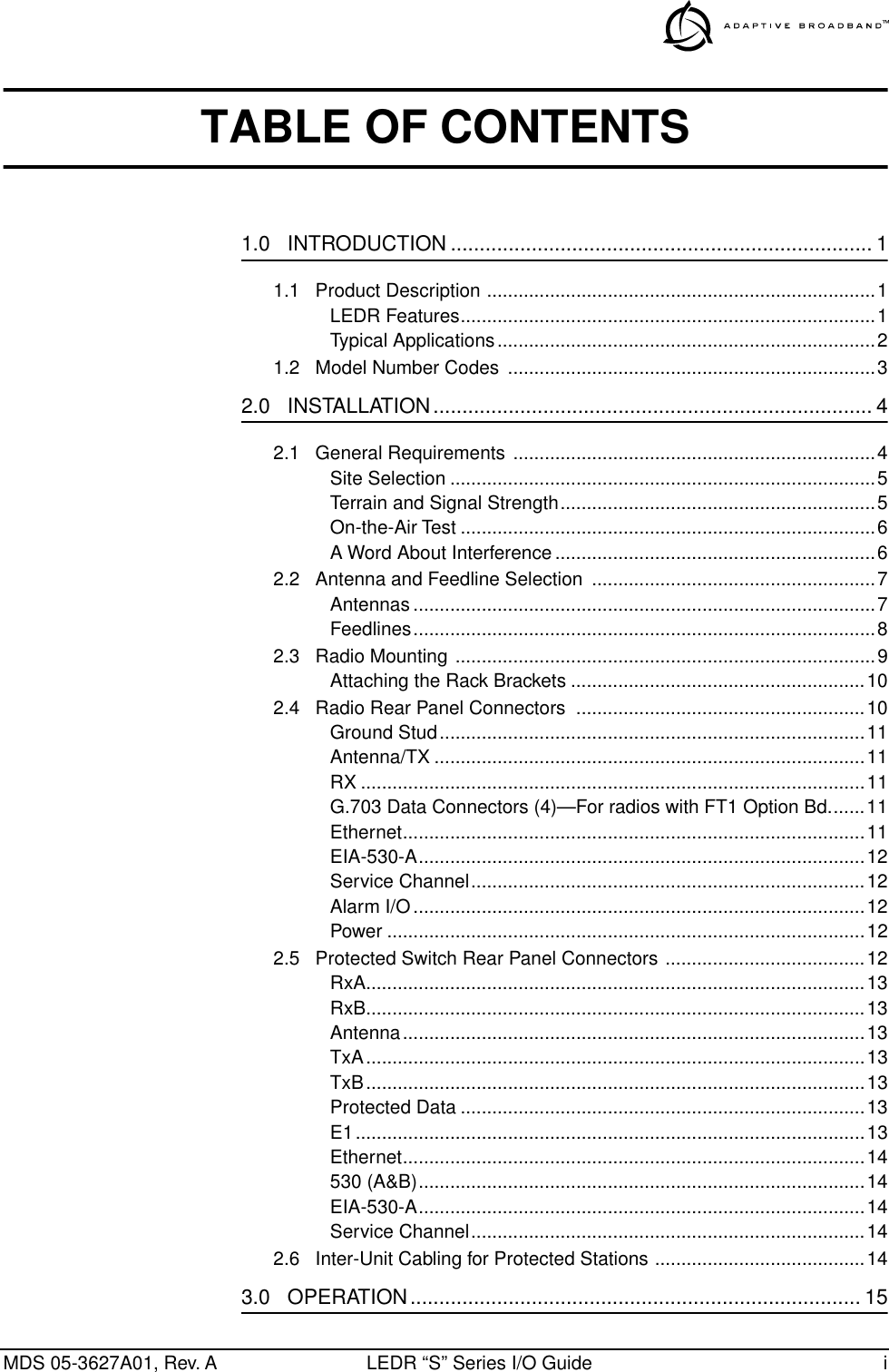
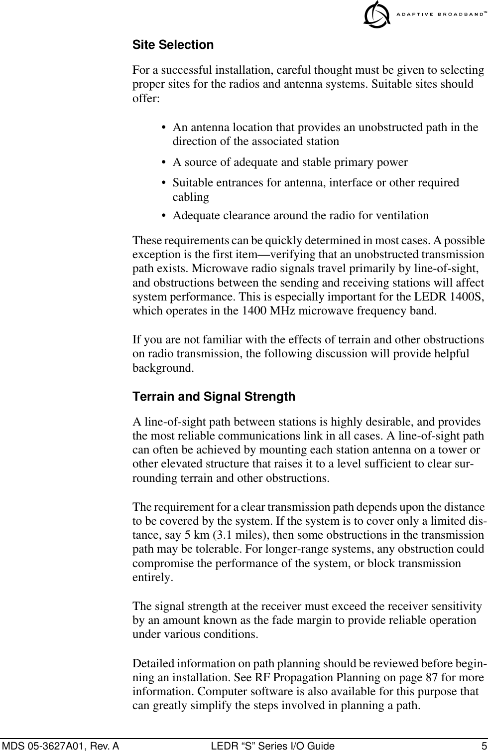
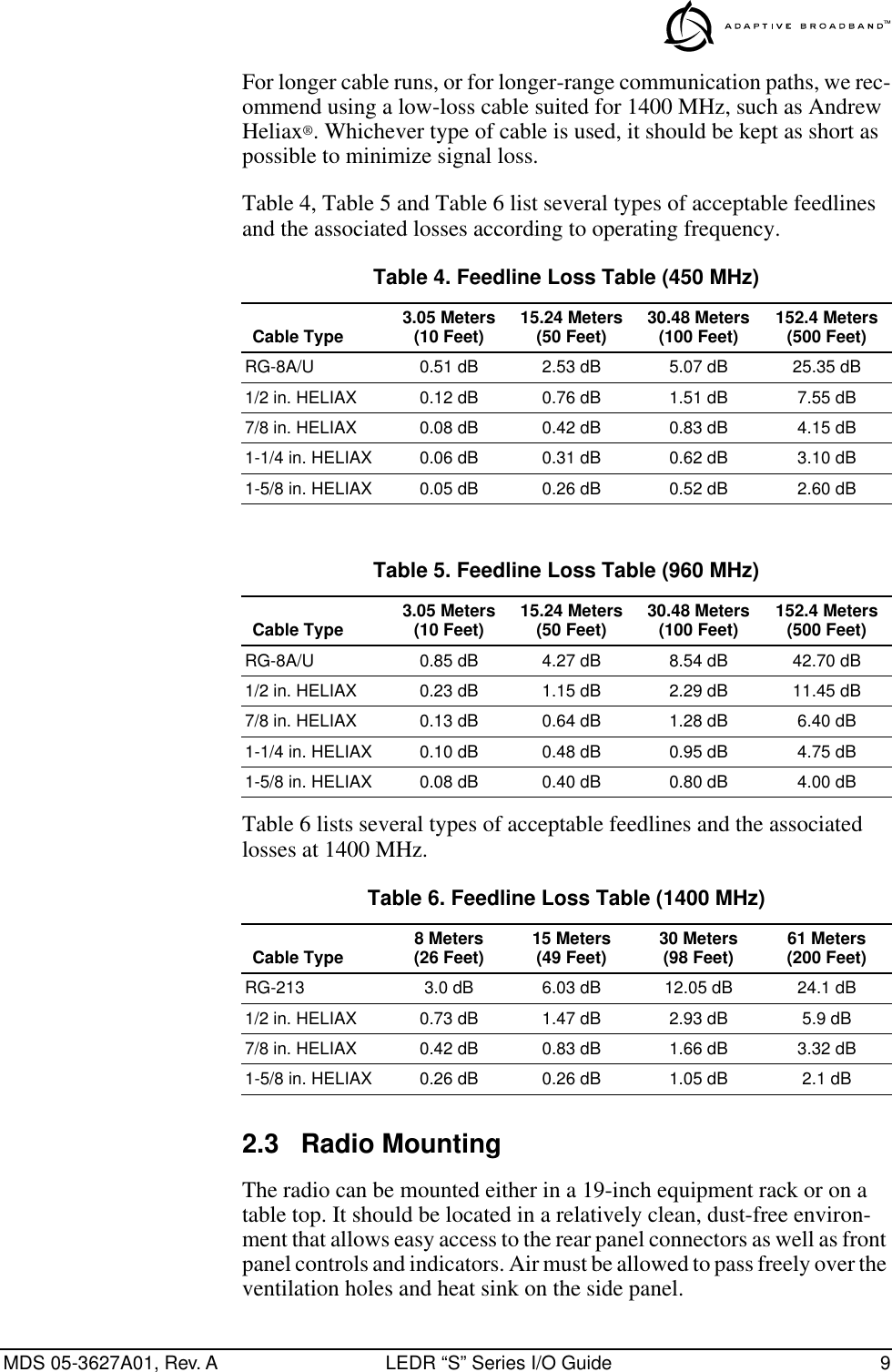
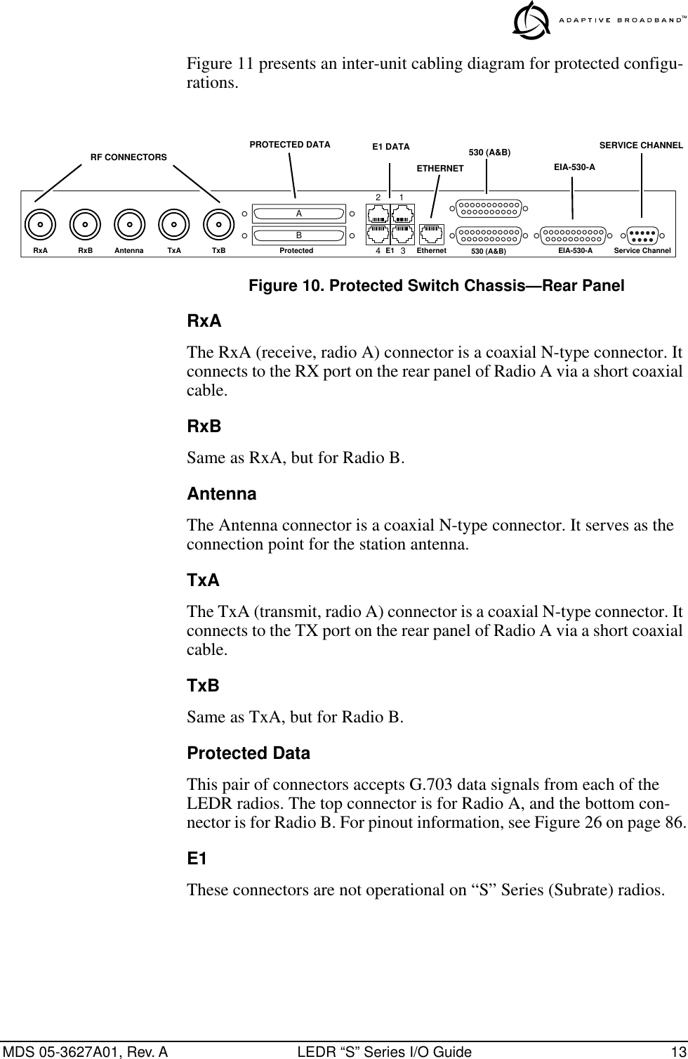
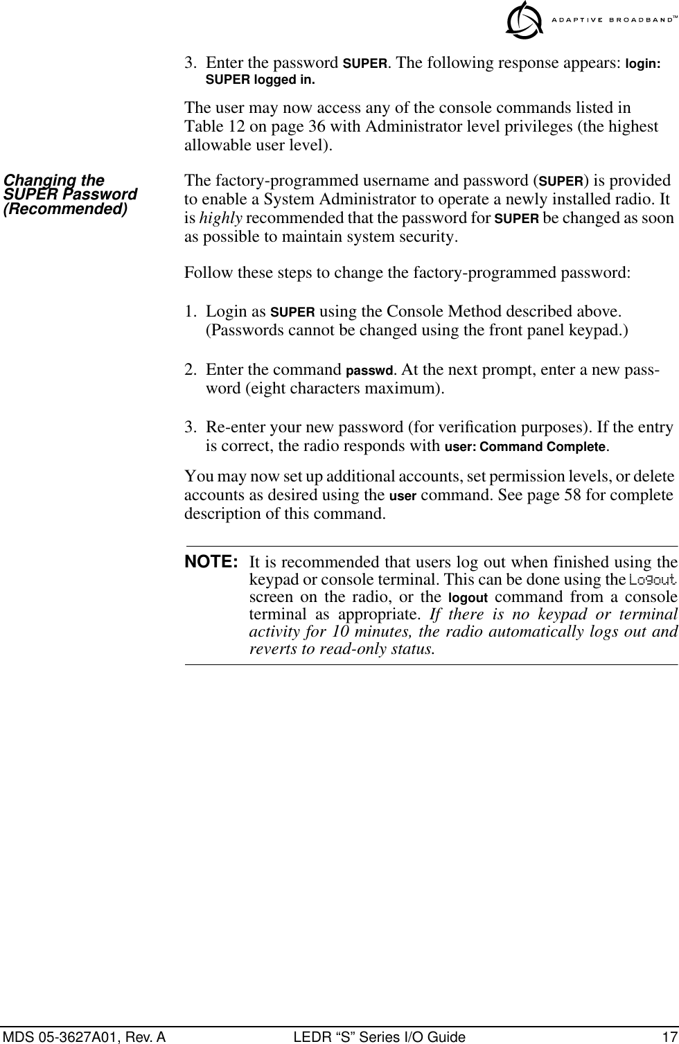
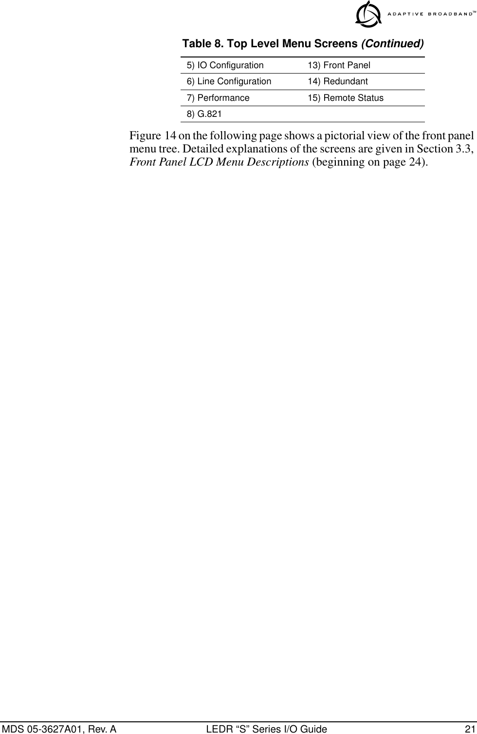
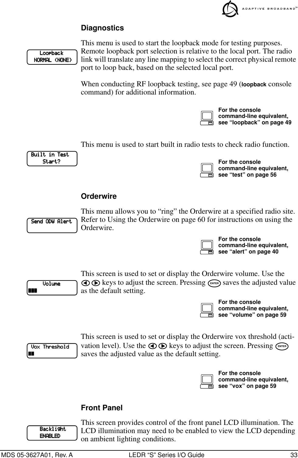
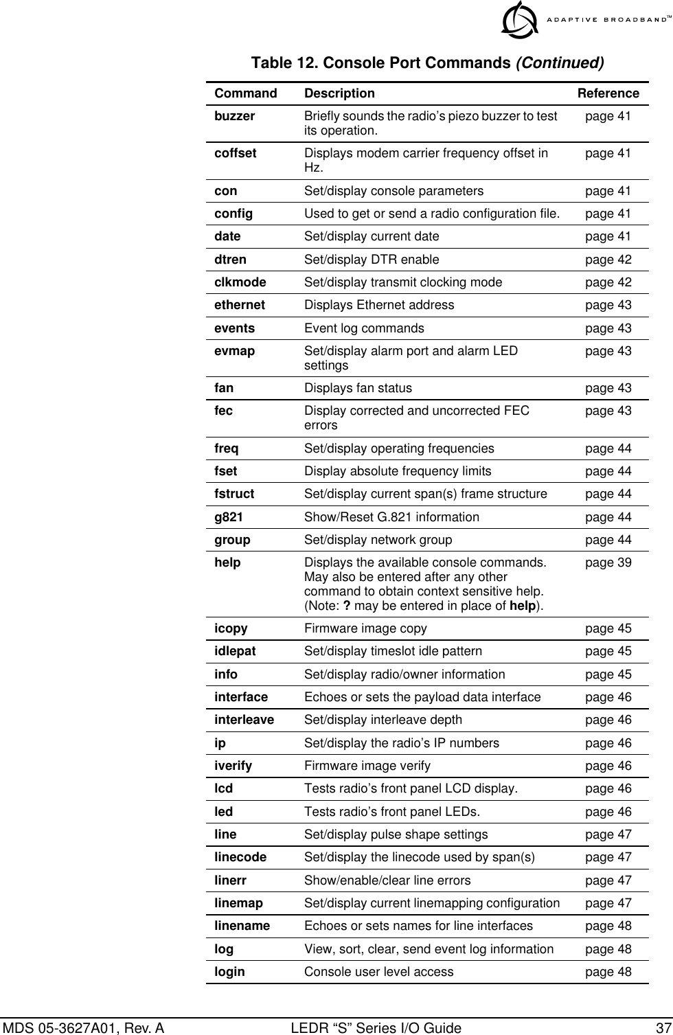
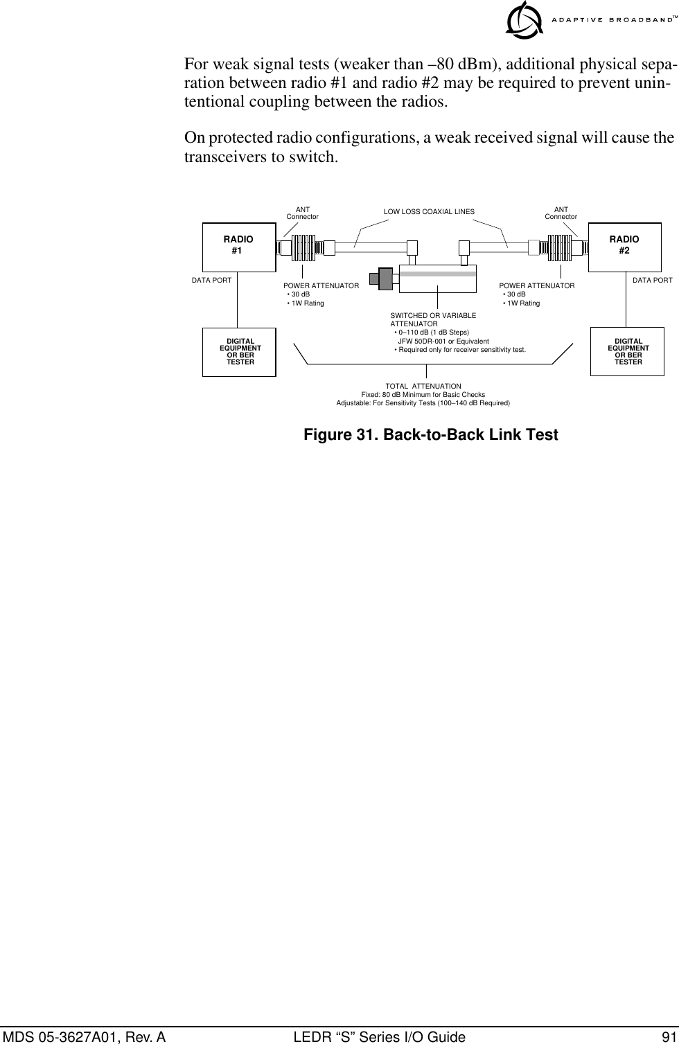
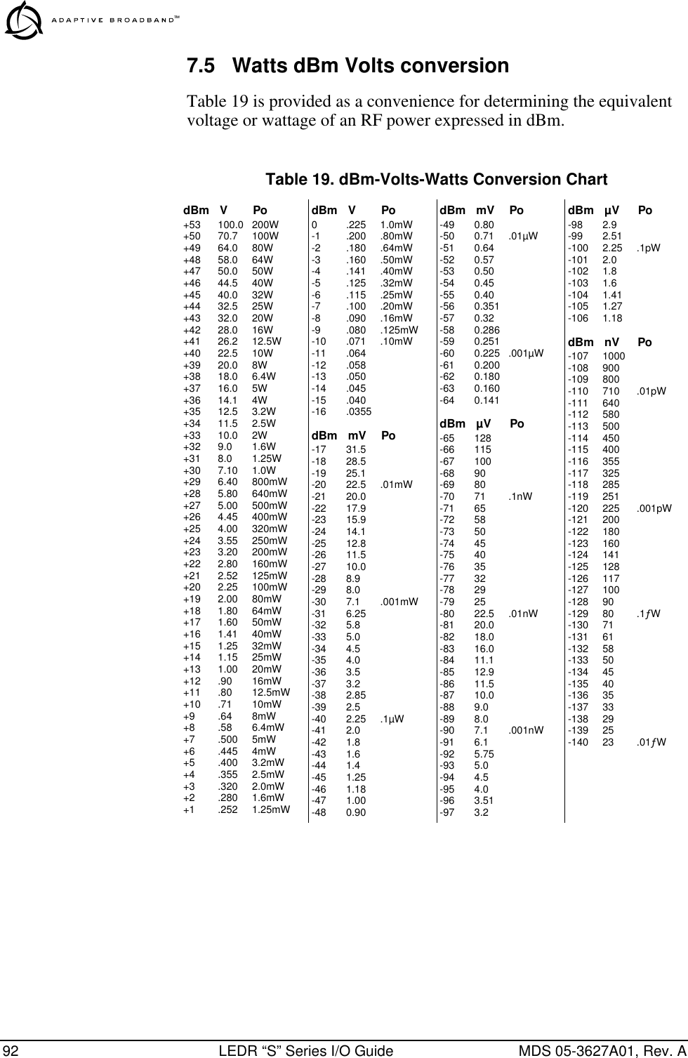
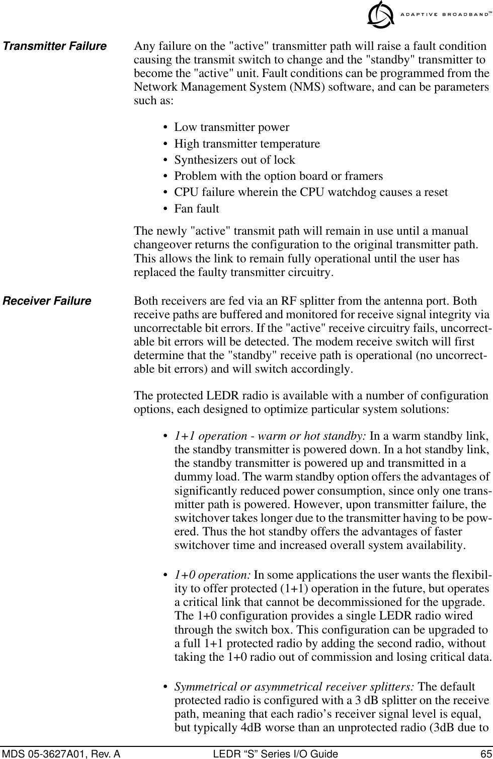
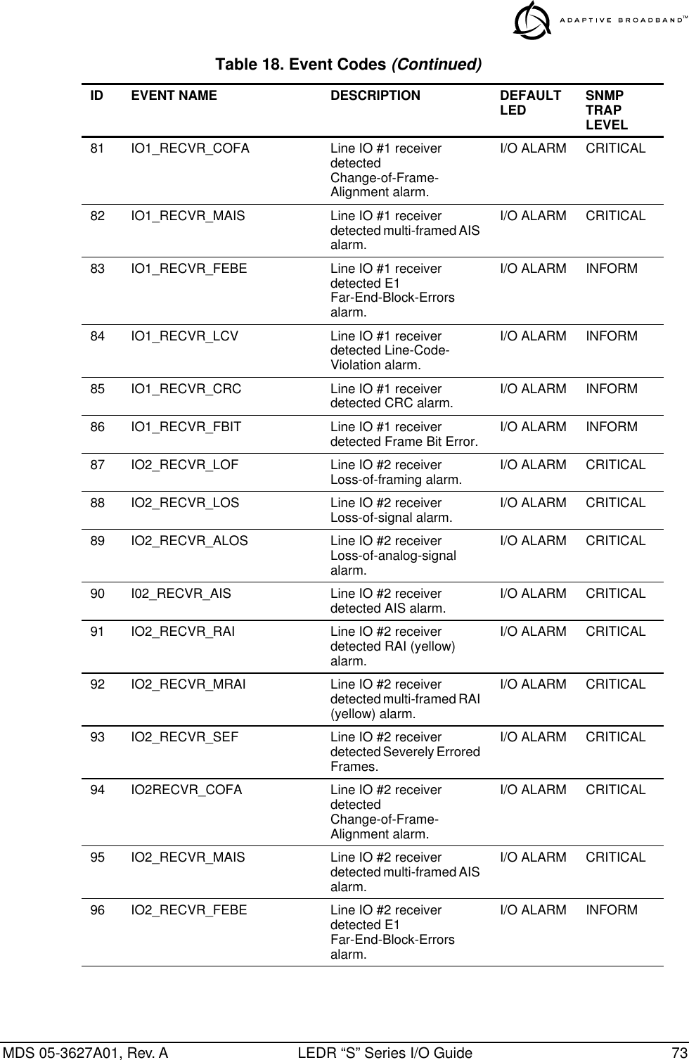
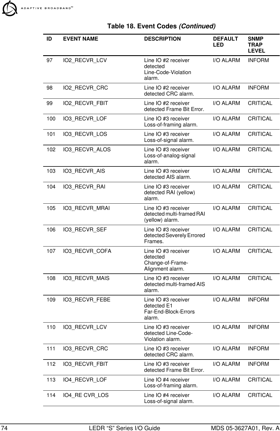
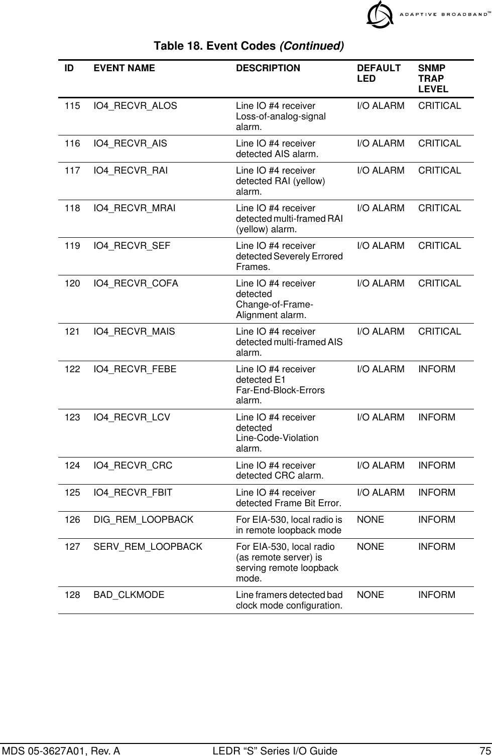
![MDS 05-3627A01, Rev. A LEDR “S” Series I/O Guide 39Command DescriptionsThe following commands are available through the console port. The conventions used for these commands are similar to UNIX com-mand-line structure. These commands all require the Enter or Return key be pressed after the command. The following conventions are used to help describe the usage of the commands. Square brackets [ ] contain subcommands that may or may not be needed as part of the desired command. If there is more than one possible subcommand a vertical line | separates the commands within the square brackets. A subcommand is an optional exten-sion of the command and changes the basic command. Angle brackets <> contain arguments. The arguments are values needed to carry out the command such as a frequency value or option. ? or help Usage: helpThis command returns a list of currently available commands. In addi-tion, entering help as a subcommand before or after a command returns usage information regarding the command. A ? (question mark) can be also be used to invoke help. Command example: rssi help Returns: Usage: command [subcommand] <argument> trend Displays continuously updated readings of: RSSI, radio temperature, RF output, signal-to-noise ratio, and FEC errors (correc ted and uncorrected).page 58txkey Key or unkey radio page 58unitid Displays the unit identification page 58uptime Displays how long the radio has been operating page 58user Administration tool for adding, modifying or deleting user accounts page 58ver Displays software version page 59volume Set/display handset volume page 59vox Set/display vox threshold page 59who Displays the radio users list page 59Table 12. Console Port Commands (Continued)Command Description ReferenceENTER](https://usermanual.wiki/GE-MDS/LEDR400S.Exhibit-22-LEDR-400S-Users-Manual/User-Guide-117319-Page-45.png)
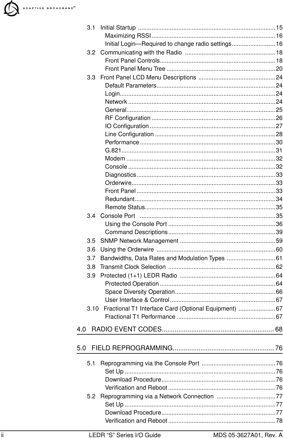
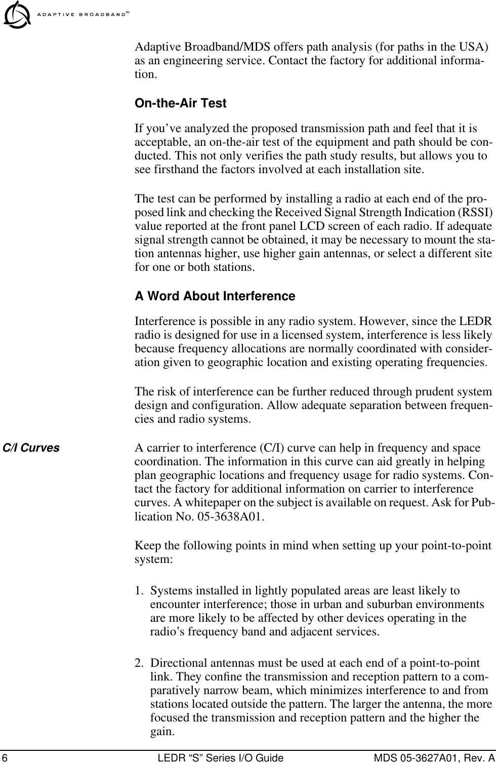
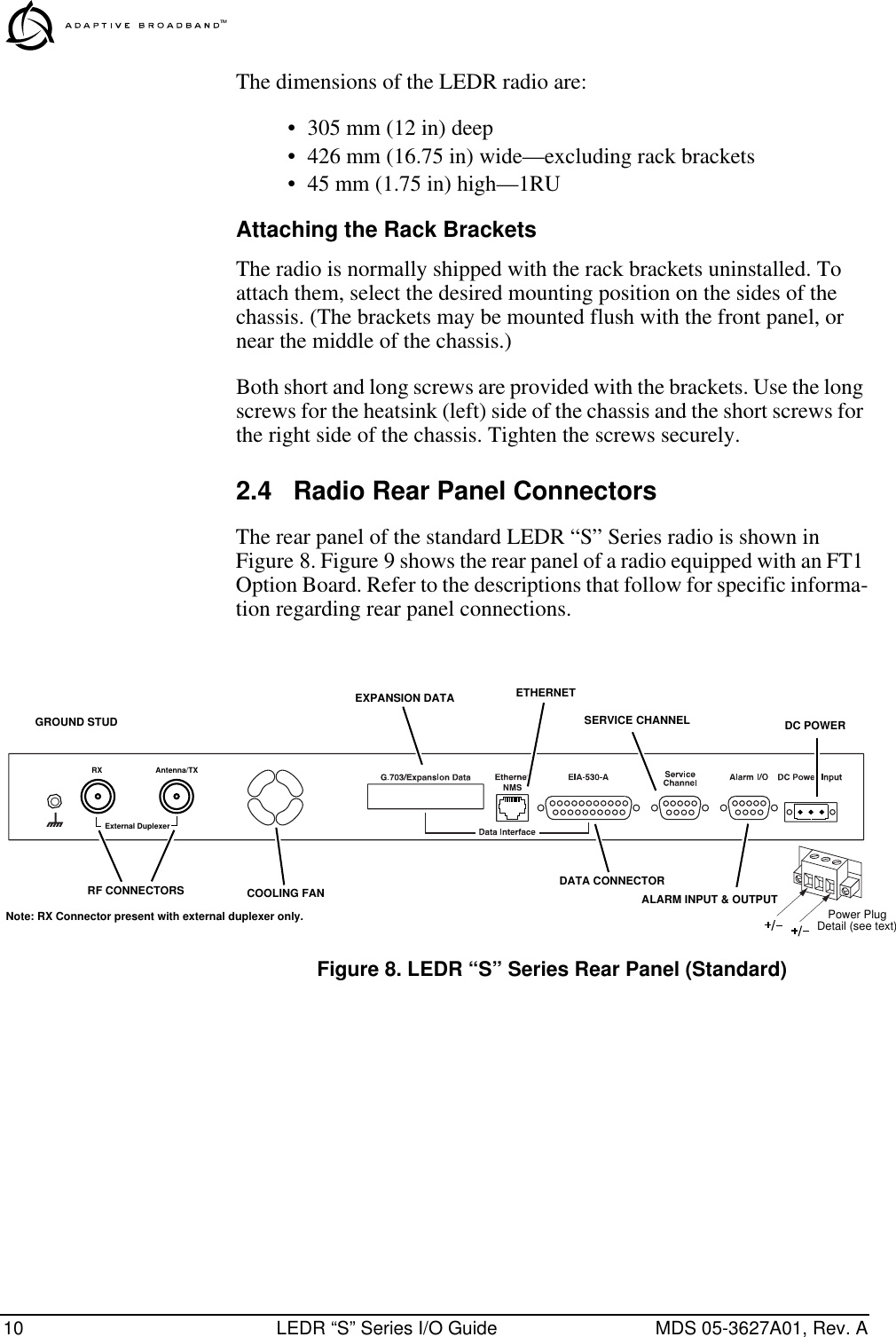
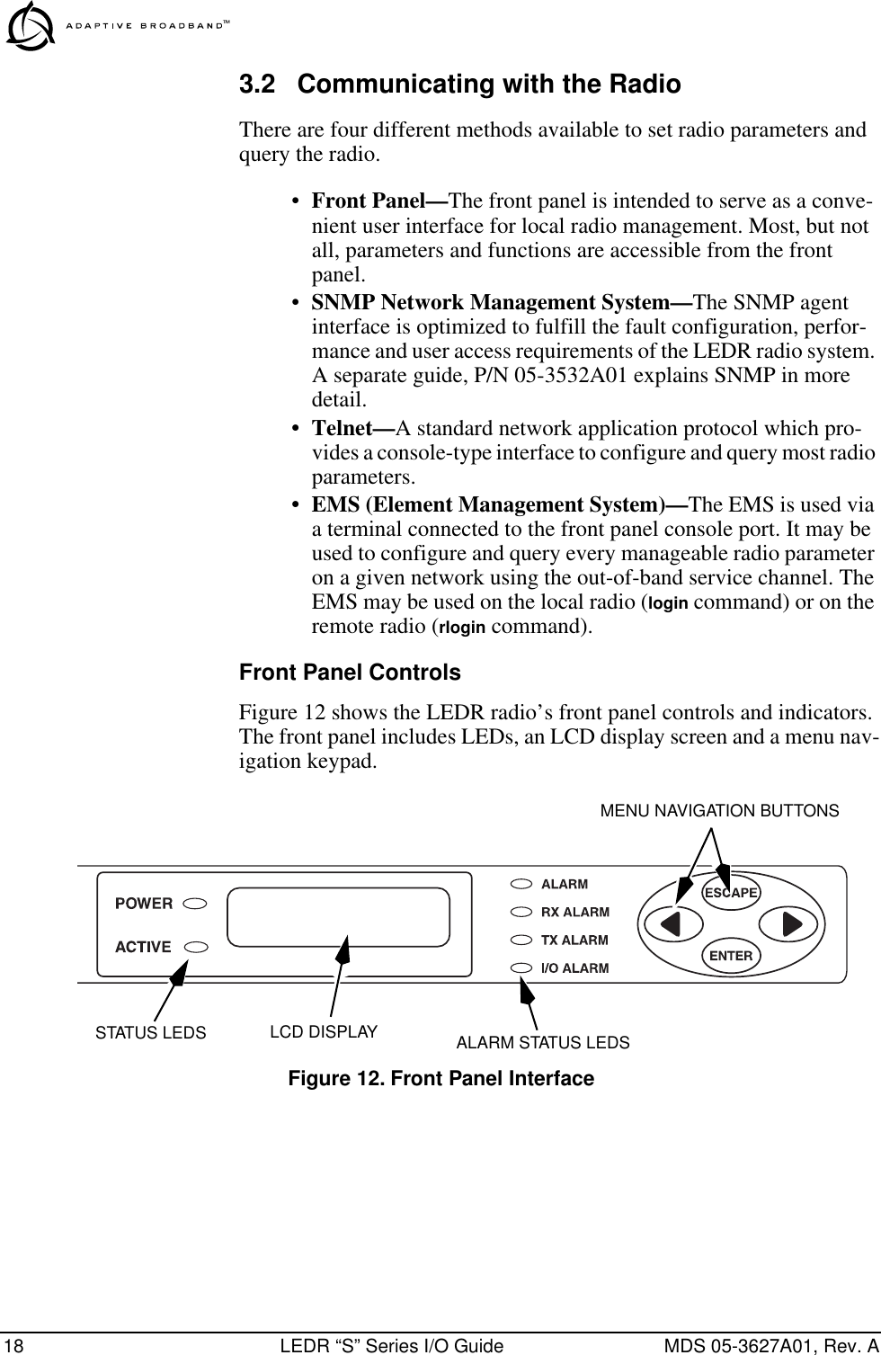
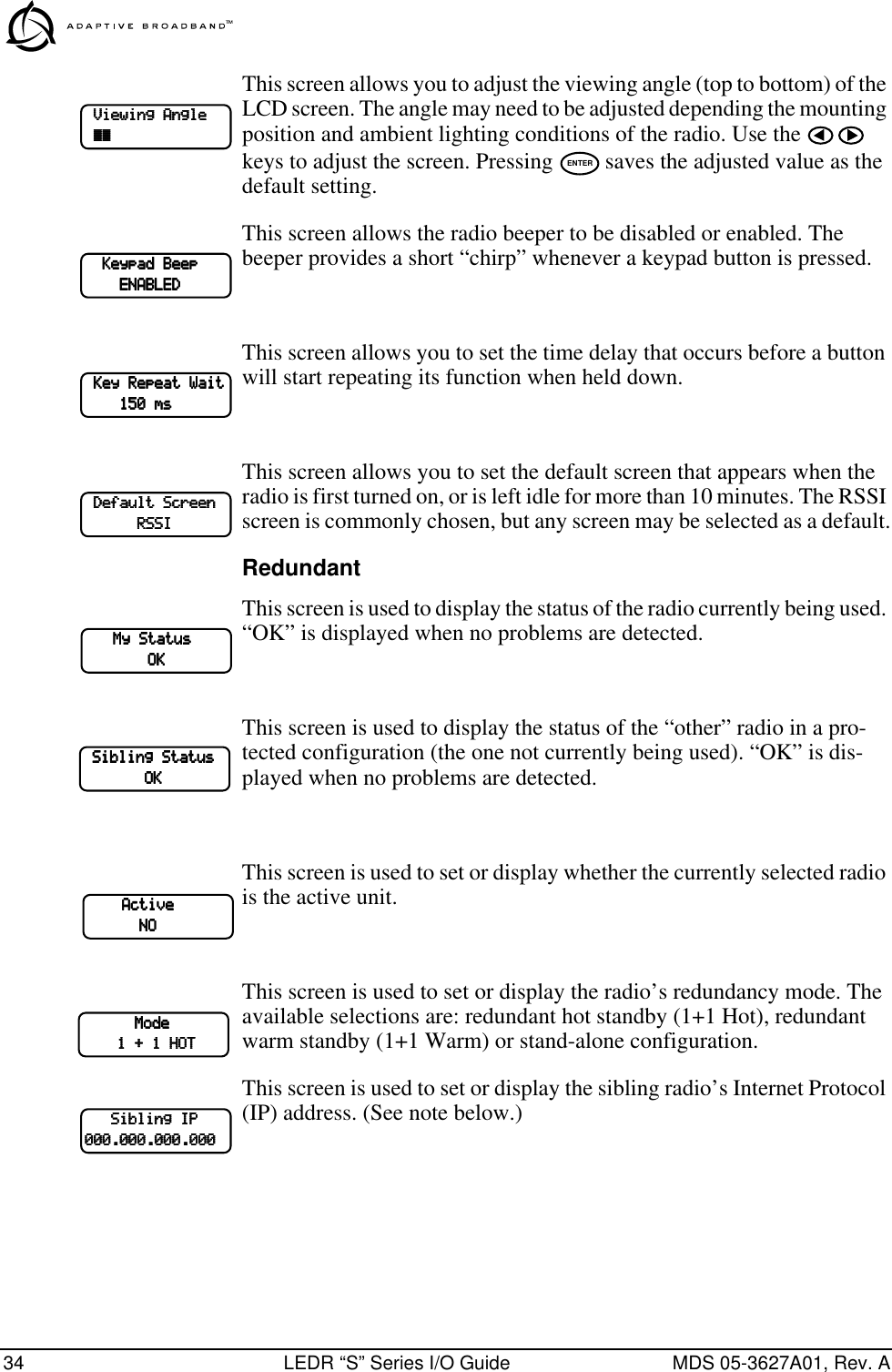
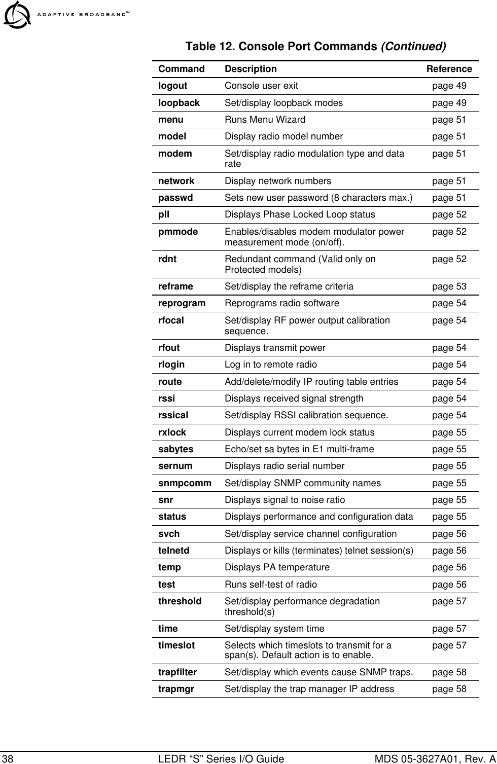
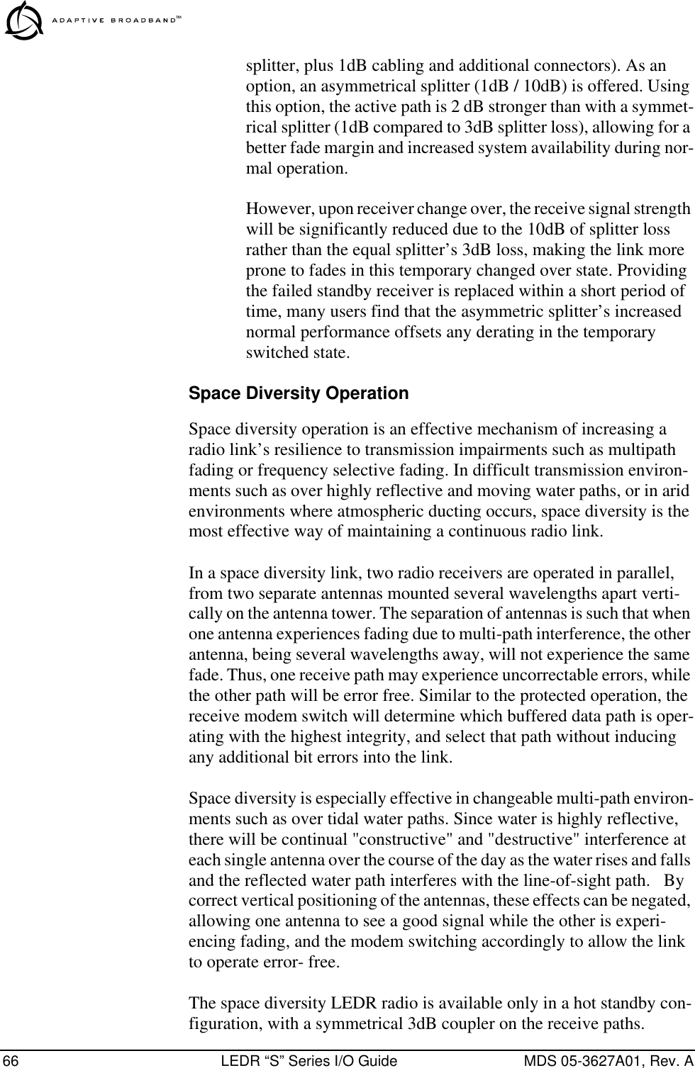
![40 LEDR “S” Series I/O Guide MDS 05-3627A01, Rev. Aais Usage: ais [linelist] [-g <on|off>] [-f <on|off>]This command enables or disables alarm signal generation and for-warding on specified lines. When generation is enabled, fault conditions within the link or at the line interface will cause the appropriate AIS/RAI signaling to occur. When forwarding is enabled, AIS/RAI sig-naling at the line interfaces will be detected and passed to the other end of the link.Command example: ais -f on -g on Returns: AIS on RAI onalarm Usage: alarm [1-4|all <open|close|read>][input [1-4|all]]This command is used to control the alarm outputs and to display the state of the alarm inputs.Command example #1:alarm all Returns: alarm: Starting test (all alarms)alarm: Test complete (all alarms)Command example #2:alarm 2 close Returns: alarm: alarm 2 closedCommand example #3: alarm input 3 Returns: alarm: alarm input 3 = openalert Usage: alert <3 digit unit ID>|allThis command is used to sound the alert buzzer on another radio station. This function allows you to signal a radio and alert someone that the handset for the Orderwire should be picked up. ENTERENTERENTERENTER](https://usermanual.wiki/GE-MDS/LEDR400S.Exhibit-22-LEDR-400S-Users-Manual/User-Guide-117319-Page-46.png)
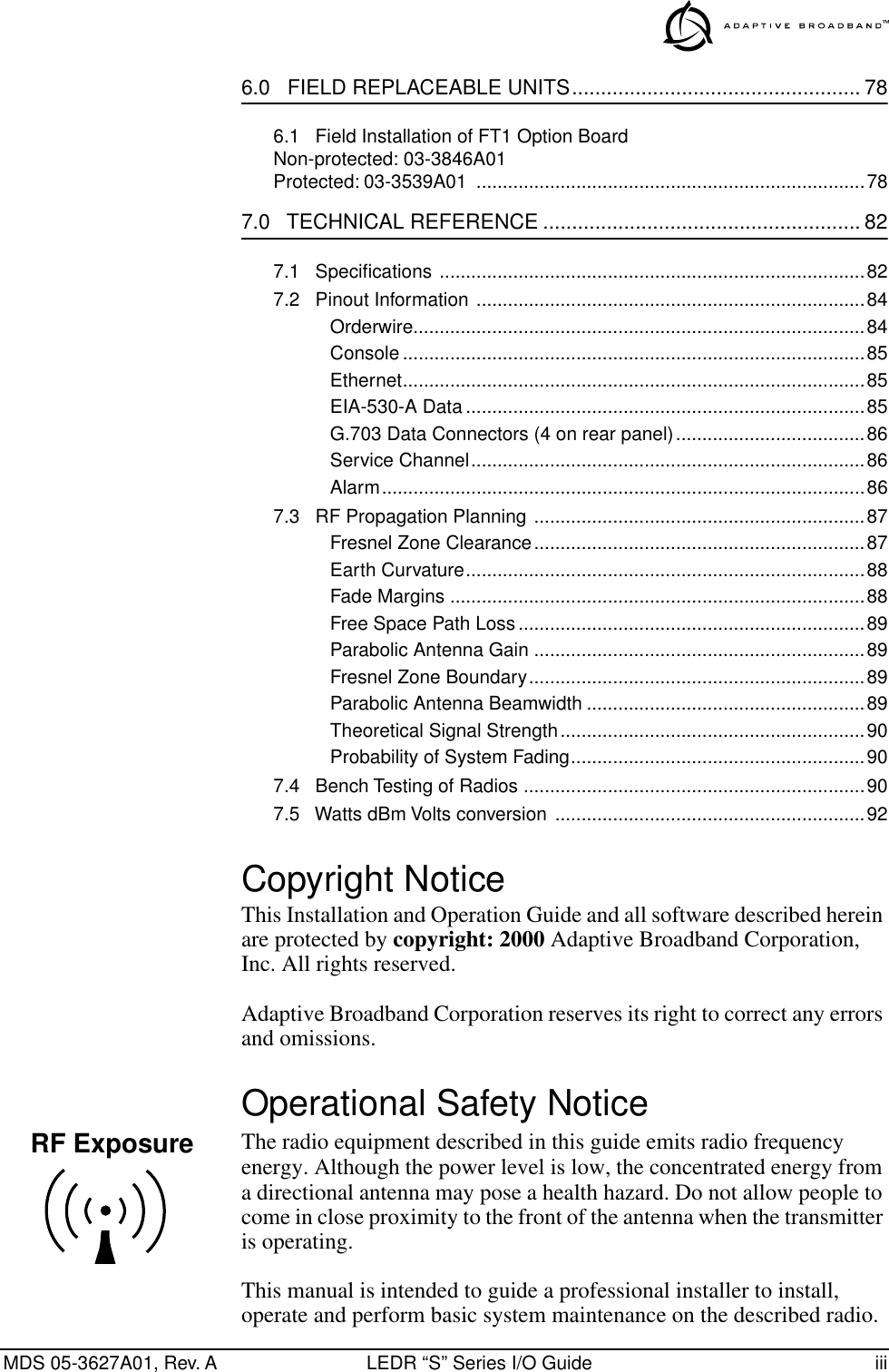
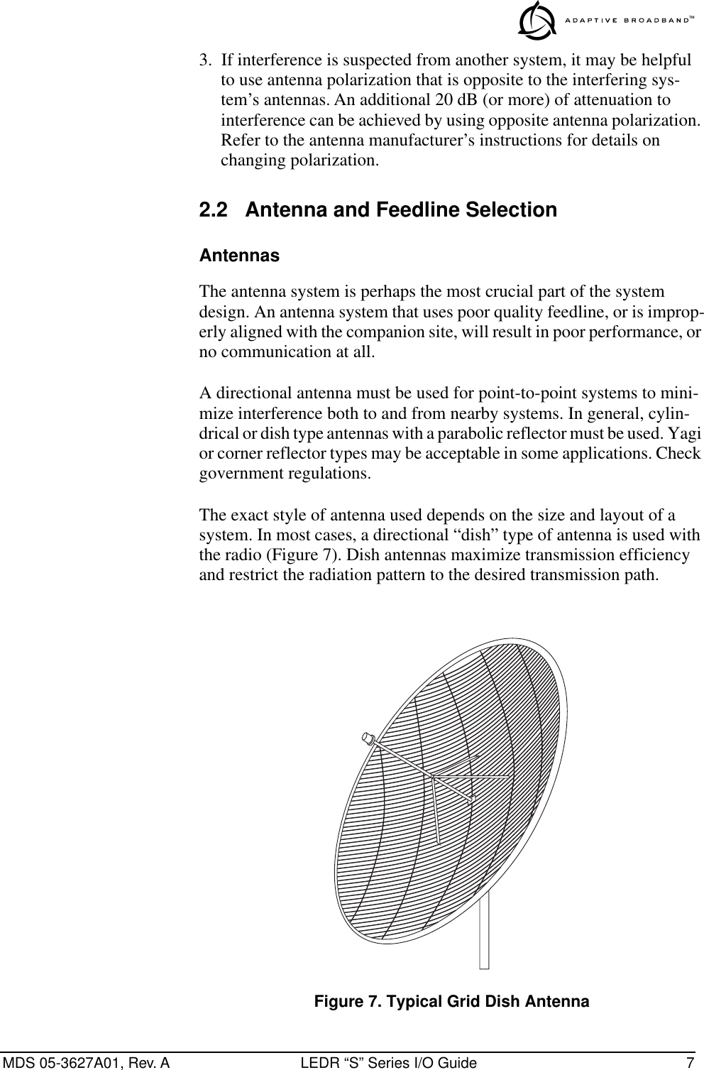
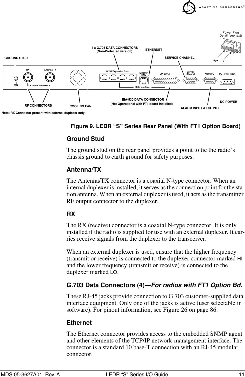
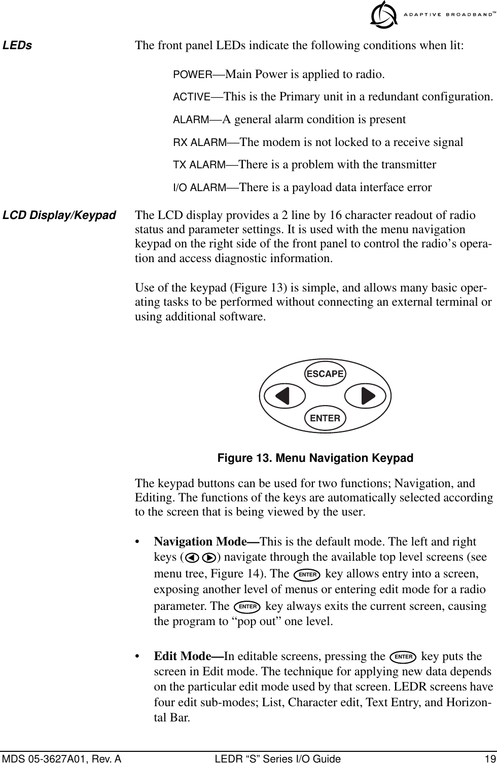
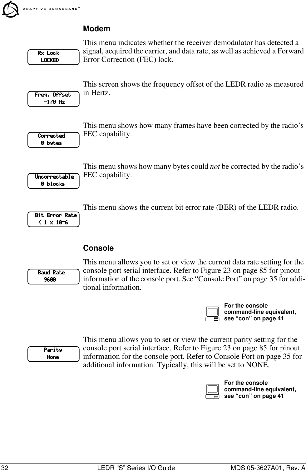
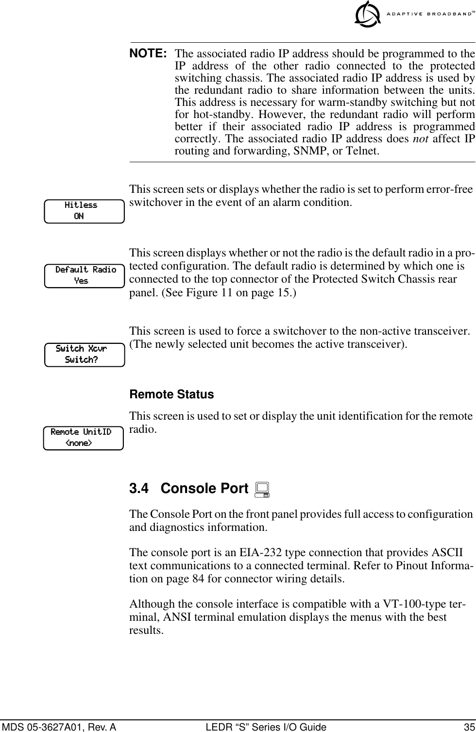
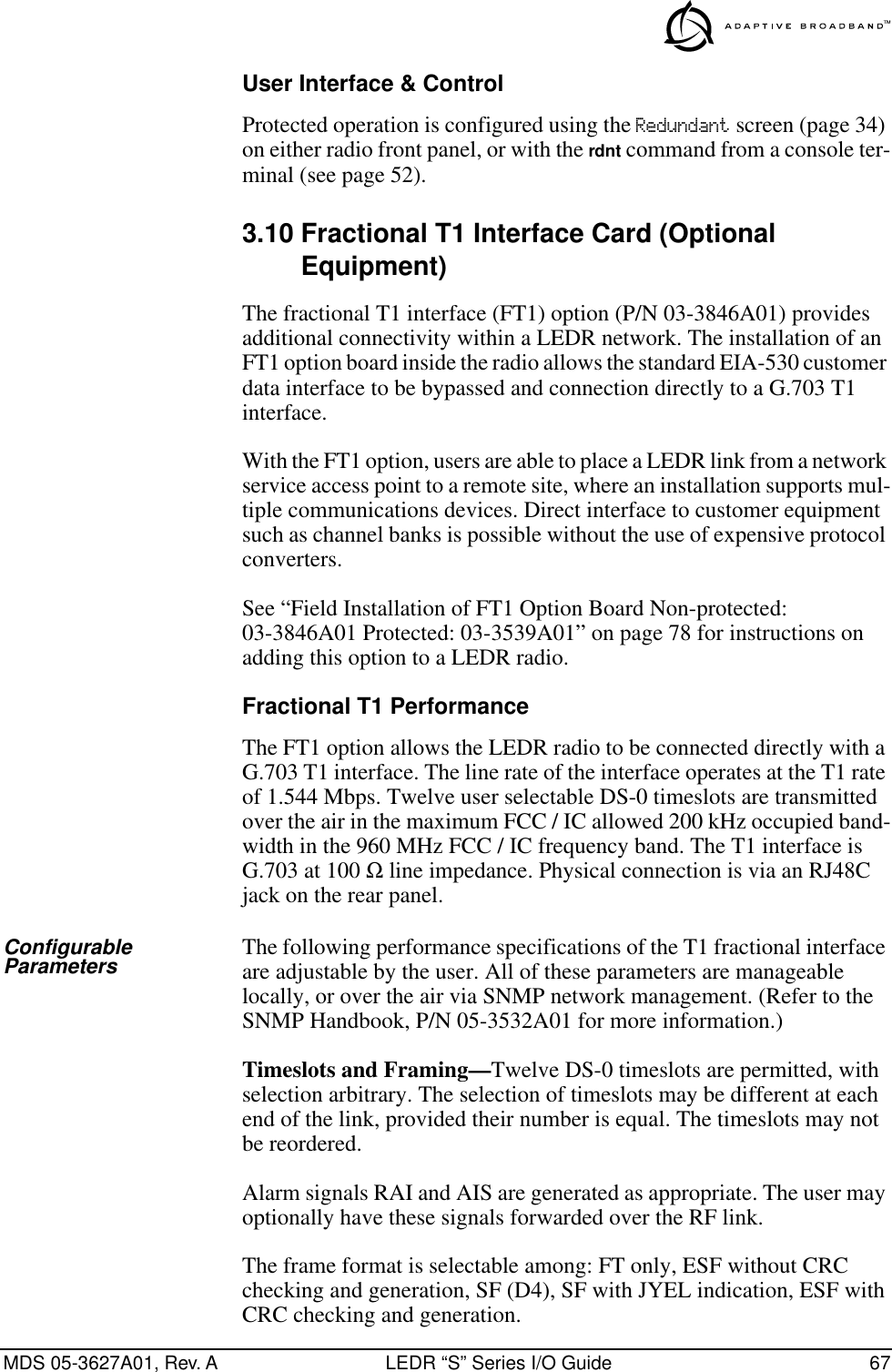
![MDS 05-3627A01, Rev. A LEDR “S” Series I/O Guide 41The three-digit number following the command indicates the unit ID of the radio that will be signaled. See “Using the Orderwire” on page 60. for more information.ber Usage: berThis command displays pre-FEC and post-FEC Bit Error Rate (BER).Returns: ber 10-6boot Usage: boot [<1-2>]This command is used to view or change the radio’s active software image. If boot is entered alone, the currently active image is displayed. A selection of 1 or 2 after the command (e.g., boot 2) indicates which software image to boot. (A message appears to confirm that you wish to reboot the software.) Upon reboot, the radio software and all radio func-tions are restarted in a manner similar to turning the radio power off and then on again. The radio is taken out of service until it reinitializes.A choice of software images allows booting an alternate version of radio software. The ability to have two radio resident software images allows radio software reprogramming over-the-air and the ability to restore operation to the original software if required.buzzer Usage: buzzerThis command briefly sounds the radio’s piezo buzzer for testing.Example response:buzzer: Starting testbuzzer: Test completecoffset Usage: coffsetThis command displays the Modem Carrier Frequency Offset.con Usage: con (baud [300|1200|2400|4800|9600|19200|38400|115200]) (parity [none|even|odd])This command sets or displays the console serial port operating param-eters. The console data rate is set or displayed using the baud subcom-mand. The parity is set or displayed using the parity subcommand.config Usage: config [get|send] [filename] [hostIP] [useCalsThis command is used to get or send a radio configuration file.](https://usermanual.wiki/GE-MDS/LEDR400S.Exhibit-22-LEDR-400S-Users-Manual/User-Guide-117319-Page-47.png)
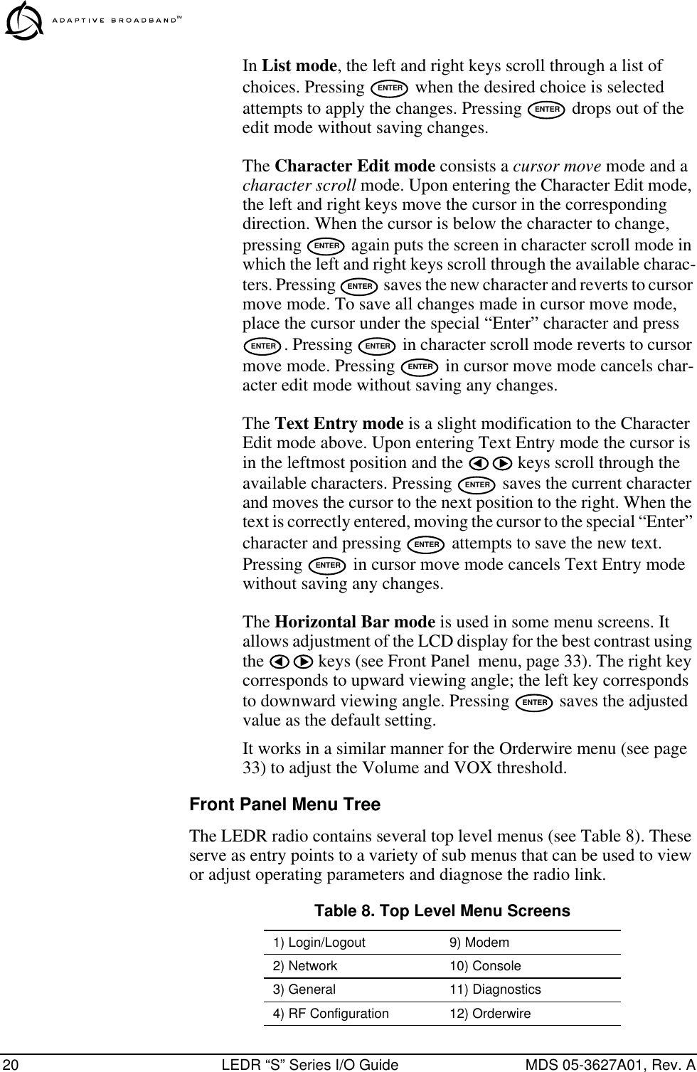
![42 LEDR “S” Series I/O Guide MDS 05-3627A01, Rev. Aclkmode Usage 1 (EIA-530 operation): clkmode [<internal|exttx|looped|extdce>] Usage 2 (E1/T1 operation): clkmode [<internal|remote|1-4|linename>] This command is used to set or display the master clock source for the radio system. Several different clocking schemes can be used. See “Transmit Clock Selection” on page 62 for clocking arrangements.NOTE: Earlier versions of the software may display the Clock Modeas NORMAL instead of INTERNAL.Usage 1 Subcommands:internal—Internal oscillator source (default).exttx—Clock from external equipment.looped—Recovered RF (RX) clock.extdce—Some other source.Usage 2 Subcommands:internal—Internal oscillator source (default).remote—Over-the-air, RX data derived.1-4—Recovered RF (RX) clock.linename—Loop timing from specified line interface.In E1/T1 operation only, the clkmode command allows the various pos-sible clock sources to be prioritized for fallback. As timing sources become available, the highest-priority source will be chosen by the system. If attaching to the network or equipment that provides timing, a universal form of the command would be clkmode 1234 internal. If attaching to equipment that will provide looped-back timing, a uni-versal form of the command would be clkmode remote internal. If both ends of the link provide looped-back timing, the internal clock source should be selected by entering clkmode internal. Note that at least one end of the link should have either network or internal timing selected.date Usage: date [MM/DD/YYYY]Subcommands: date format [<1-3>] (1-US, 2-European, 3-generic)This command sets or displays the date and time of the radio’s internal real-time clock. The real time clock operates from an internal lithium battery so it is running even if the radio has no DC power connected. The date format may also be set or displayed from this screen for one of three formats: U.S., European, or generic.The real time clock is fully compliant with year 2000 standards.Example response: date: 07-JUN-1999 08:11:30date format: dd-MON-yyyy (3)](https://usermanual.wiki/GE-MDS/LEDR400S.Exhibit-22-LEDR-400S-Users-Manual/User-Guide-117319-Page-48.png)
![MDS 05-3627A01, Rev. A LEDR “S” Series I/O Guide 43dtren Usage: dtren [<on|off>]The dtren command sets or displays the status of the DTR (handshaking) enable.Example response: dtren: onethernet Usage: ethernet This command displays the fixed hardware address of the radio’s Ethernet port. This number is assigned at the factory and cannot be changed.events Usage: events [subcommand] [<arguments>]Subcommands: pendingfilter [event#] [count]initdesc [<event#>]This command allows viewing the pending events (pending), setting the number of occurrences per log entry (filter), initializing events pro-cessing (init) and display of event descriptions (desc). To turn off log-ging for a particular event, the filter count value should be set to zero.Example response: events {events}: -DEMOD_ACQUISITION (Event #27)events: Event#0 Filter count=1events {init}: The event log has been re-initializedevents {desc}: Event#40 Description-IO2_DIG_REM_LPBACKevmap Usage: evmap [subcommand] [event #] [arguments]Subcommands: led [ioalarm|txalarm|rxalarm|alarm|active] [...]aout [1|2|3|4] [...]dumpThis command sets or displays which radio system events cause alarm indications on the front panel LEDs or the rear panel ALARM I/O con-nector. The subcommands specify which output will be asserted upon occurrence of an event #. Multiple outputs can be specified with spaces between them.See Figure 12 for reference of the Front Panel LEDs. Refer to Alarm on page 86 for the pinouts of the Alarm I/O connector.Example response: evmap: Event #0 LED alarmevmap: Event #0 Alarm Output NONEfan Usage: [fan]This command is used to read the status of the radio’s cooling fan.Example response: fan1: Workingfan2: Workingfec Usage: [fec <clr>]](https://usermanual.wiki/GE-MDS/LEDR400S.Exhibit-22-LEDR-400S-Users-Manual/User-Guide-117319-Page-49.png)
![44 LEDR “S” Series I/O Guide MDS 05-3627A01, Rev. AThis command displays corrected and uncorrected FEC errors.Example response: fec: 1812992 Correctable Bytesfec: 6912 Uncorrectable Blocksfreq Usage: freq [<tx/rx>] [<freq>] [<freq>]This command sets or displays the transmit and receive frequency.Example response: freq {TxFreq}: 942175000 Hzfreq {RxFreq}: 944175000 Hzfset Usage: fset [<min freq>] [<max freq>]This command sets the absolute frequency limits of the LEDR radio.Example response: fset {MinFreq}: 900000000fset {MaxFreq}: 960000000fstruct Usage: fstruct [linelist] [mode <0-7>]This command is used to set or display the span(s) frame structure. The [linelist] variable represents a list of line interfaces. This entry can be either a single line number or linename (see linename command), a comma separated list of line numbers or linenames, a range of line num-bers (i.e., 1-4), or if linelist is not given all lines. Table 13 shows a list of valid line numbers.g821 Usage: demod|io1|io2|io3|io4|all[clr]This command is used to show or reset the radio’s G.821 information.Example Response: Demodulator: ERROR FREESavail: 1036Sunavail: 0ES: 0SES: 0group Usage: [<group>]Table 13. T1/E1 Line Numbers Mode for T1 Mode for E10–FT only (default) 0–FAS only (default)1–ESF 1–FAS + BSLIP2–ESF + PRM 2–FAS + CRC3–SF 3–FAS + CRC + BSLIP4–SF + JYEL 4–FAS + CAS5–ESF + CRC 5–FAS + CAS + BSLIP6–ESF + CRC +PRM 6–FAS + CRC + CAS7–FAS + CRC + CAS + BSLIP](https://usermanual.wiki/GE-MDS/LEDR400S.Exhibit-22-LEDR-400S-Users-Manual/User-Guide-117319-Page-50.png)
![MDS 05-3627A01, Rev. A LEDR “S” Series I/O Guide 45This command sets or displays the network group that the radio is oper-ating in.Example response: group: 1help or ? Usage: helpThis command can be used alone or with a specific command. Entering help before or after a command will display the usage and possible sub-commands of the command. The character ? may also be used to obtain help.icopy Usage: icopy [<app|dsp|fpga|scripts>]This command is used to copy the active software image to the inactive software image. There are two independent radio operating software files residing in the radio. The radio uses one of the files as the active software which is run-ning. The other software file is inactive and is not running. The ability to have two radio software images allows radio software reprogram-ming to be done over-the-air and provides the ability to restore operation to the original software if required.To run the software image see “boot” on page 41.idlepat Usage: idlepat [<linelist>] [slots <slotlist>] <pattern>This command is used to set or display the timeslot(s) idle pattern.variable definitions:linelist: Represents a list of line interfaces. It can consist of a single line number or linename, a comma separated list of line numbers or line-names, a range of line numbers (i.e., 1–4), or if linelist is not given all lines. See Table 13 on page 44 for a list of line numbers.slotlist: A list of timeslots consisting of a single slot number, comma sep-arated list of slot numbers, or a range of slot numbers (i.e., 2-8).pattern: A 2 hex digit value (default value is 17).info Usage: info [<owner|contact|name|location>] [<string>]This command is used to program information into radio memory that is particular to the radio site or installation. The information is intended for identification and memorandum needs. Four separate text fields are provided. The owner’s name string is lim-ited to 10 characters. The contact, location, and name text fields are lim-ited to 254 characters. Any standard, printable ASCII characters are allowed.](https://usermanual.wiki/GE-MDS/LEDR400S.Exhibit-22-LEDR-400S-Users-Manual/User-Guide-117319-Page-51.png)
![46 LEDR “S” Series I/O Guide MDS 05-3627A01, Rev. ATo display the owner’s name text field enter info owner. To display the contact information enter info contact. To display the name information enter info name. To display the location information enter info location.To display all the parameters enter info. To change the info text, enter text after info owner or other info field name.interface Usage: interface: [e1|t1]This command is used to set or display the payload data interface. The user may select between EIA-530 and T1, or EIA-530 and E1.Example response:interface: {Line}: e1interleave Usage: interleave [depth]This command is used to set or display the interleave depth.Example response:interleave: 1ip This command sets or displays the Internet Protocol (IP) data for the LEDR radio. The subcommands allow you to set the IP address, IP net-mask, IP gateway, or IP port.Usage: ip [subcommand] [<argument>]Subcommands: address [x.x.x.x]netmask [x.x.x.x]gateway [x.x.x.x]IP port [ETH|AIR]See “Network” on page 24 for additional information.Example response: IP Address: 10.2.142.143IP Netmask: 255.255.0.0IP Gateway: 0.0.0.0IP Port: ETHiverify Usage: iverify [1–2] [<app|dsp|fpga|scripts>]This command is used to determine the data integrity of the two soft-ware image files that reside in the radio. (See also icopy, above.)Example response:iverify: Image has been verifiedlcd Usage: lcd [<on|off|restore>]](https://usermanual.wiki/GE-MDS/LEDR400S.Exhibit-22-LEDR-400S-Users-Manual/User-Guide-117319-Page-52.png)
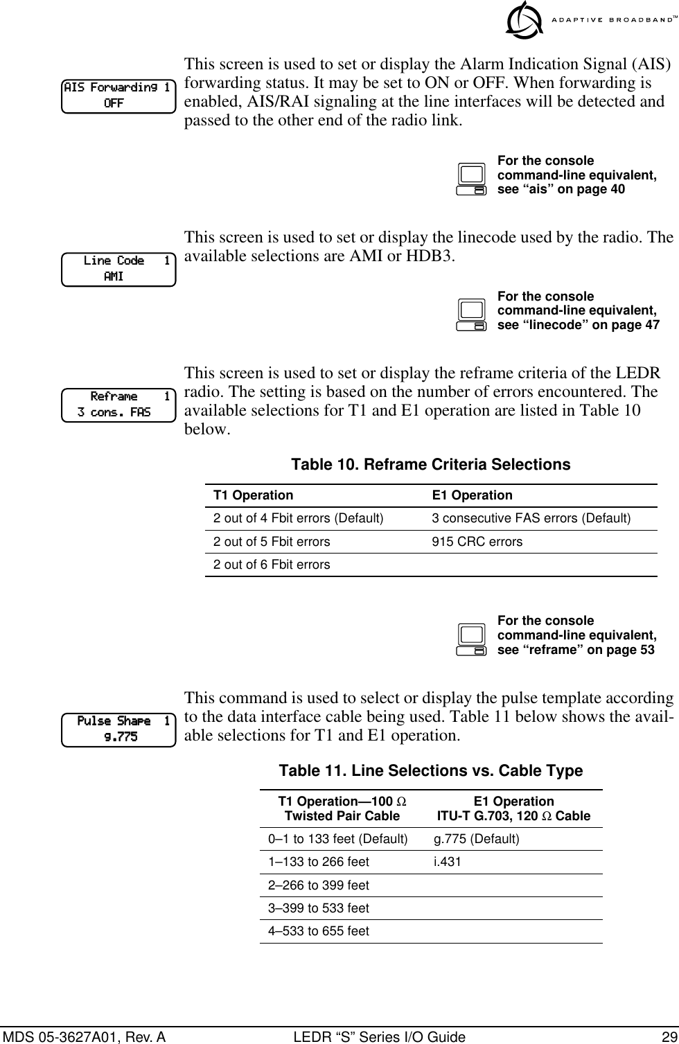
![MDS 05-3627A01, Rev. A LEDR “S” Series I/O Guide 47This command starts a two-part test of the radio’s front panel LCD. When lcd is first entered, the display should appear with all blocks. When the Return key is pressed, the screen should change to completely blank.led Usage: led [<alarm|rxalarm|txalarm|ioalarm|all|restore>] [<on|off>]This command is used to test the front panel LEDs. If no argument is given, all front panel LEDs (except POWER) should flash in sequence. Press Control-C to end the test.Command example:led alarm onReturns:led: Alarm LED ONline Usage: line [linelist] [cable <0-4> [spec]This command is used to set or display the pulse template according to the cable characteristics shown in Table 14 below.linecode Usage: linecode [linelist] [HDB3|AMI]This command sets or displays the radio’s linecode (B8ZS or AMI in T1 mode, HDB3 or AMI in E1 mode).The [linelist] variable represents a list of line interfaces. It can consist of a single line number or linename, a comma separated list of line num-bers or linenames, a range of line numbers (i.e., 1–4), or if linelist is not given all lines. See Table 13 on page 44 for a list of line numbers.Example response:linecode: HDB3linerr Usage: linerr [linelist] [on|off]Table 14. Line Selections vs. Cable Type T1 Operation—100 Ω Twisted Pair Cable E1 OperationITU-T G.703, 120 Ω Cable0–1 to 133 feet (Default) g.775 (Default)1–133 to 266 feet i.4312–266 to 399 feet3–399 to 533 feet4–533 to 655 feet](https://usermanual.wiki/GE-MDS/LEDR400S.Exhibit-22-LEDR-400S-Users-Manual/User-Guide-117319-Page-53.png)
![48 LEDR “S” Series I/O Guide MDS 05-3627A01, Rev. AThis command is used to display, enable, or disable line errors. The [linelist] variable represents a list of line interfaces. It can consist of a single line number or linename, a comma separated list of line numbers or linenames, a range of line numbers (i.e., 1–4), or if linelist is not given all lines. See Table 13 on page 44 for a list of line numbers.linemap Usage: linemap [maplistThis command is used to set or display the current span mapping con-figuration. The maplist variable consists of from 1 to 4 alpha-numeric characters specifying line interface to span mapping. Valid numbers are 1–4. Valid span characters are a–d.Example: Entering linemap 1d 2b 3a 4c causes the following:maps line 1 to span dmaps line 2 to span bmaps line 3 to span amaps line 4 to span clinename Usage: linename <linelist> <namelist>This command is used to set or display the names for line interfaces.The [linelist] variable represents a list of line interfaces. It can consist of a single line number or linename, a comma separated list of line numbers or linenames, a range of line numbers (i.e., 1–4), or if linelist is not given all lines. See Table 13 on page 44 for a list of line numbers.The namelist variable consists of a list of names. It can consist of a single name or a comma/whitespace separated list of names. Names can be up to 16 characters long.log Usage: log [subcommand] [<argument>]Subcommands: view [critical|major|minor|inform]]filter [event #] [count]]clearsend [filename] [hostIP]This command is used to display and manage the event log file as fol-lows: The view subcommand displays the list of events with the associated time and date as well as other system parameters. The filter subcommand is used to sort events. The clear subcommand resets the event log and purges all events from memory. The send subcommand uploads the send event log information to an IP address using TFTP protocol.](https://usermanual.wiki/GE-MDS/LEDR400S.Exhibit-22-LEDR-400S-Users-Manual/User-Guide-117319-Page-54.png)
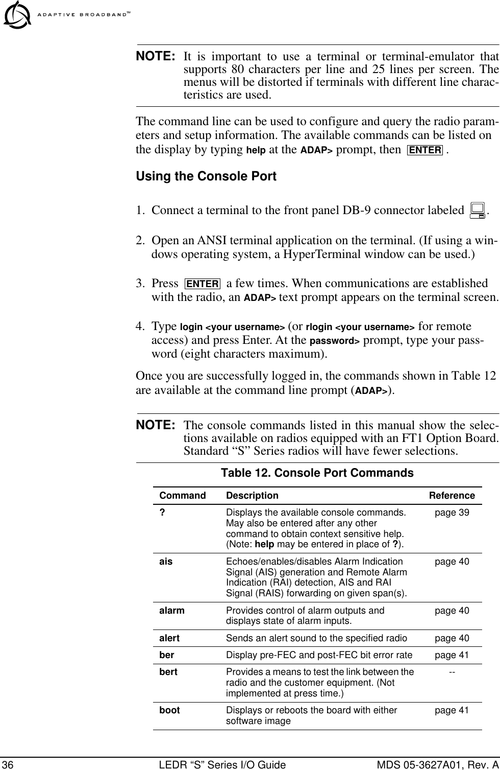
![MDS 05-3627A01, Rev. A LEDR “S” Series I/O Guide 49login Usage: loginThis command allows access to configuration and diagnostics informa-tion as allowed by the radio system administrator. Example:ADAP> login .Returns:Username>Type: john (or appropriate user name) Returns:Password>Type: (password) NOTE: Passwords must not exceed eight characters.See user command on page 58 for more information on user access levels.logout Usage: logoutThis command is used to log out as a user of the radio configuration and diagnostics functions. loopback Usage 1: loopback none|rf|local|remote|iol [linelist]|ior [linelist] <timeout>]Usage 2: loopback [inb|outb] [linelist] [on|off] [-u <code>] [-d <code>]The loopback command is used to set or display the loopback mode that can be used for diagnostic purposes. Entering loopback without any parameters displays the current loopback mode.Usage 1 subcommands:The none subcommand disables all loopback operation. This is the mode for normal point-to-point operation. The rf subcommand enables an RF loopback mode. This mode allows testing of the local transceiver’s transmit and receive chain. RF loopback testing is a valuable diagnostic tool, but it should not be considered an exhaustive test of the transceiver. In some cases, interac-tion between the transmit and receive phase-locked loops (PLLs) can occur, causing erroneous results during testing. Changing the trans-ceiver’s RF output setting may resolve these problems.ENTERENTERENTER](https://usermanual.wiki/GE-MDS/LEDR400S.Exhibit-22-LEDR-400S-Users-Manual/User-Guide-117319-Page-55.png)
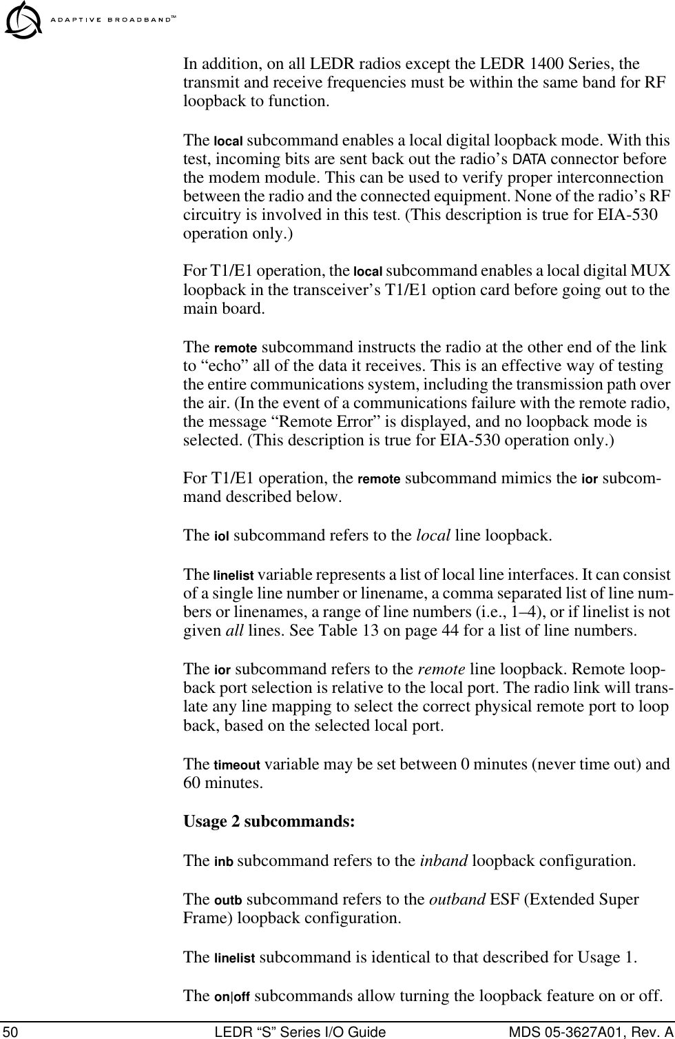
![MDS 05-3627A01, Rev. A LEDR “S” Series I/O Guide 51The -u <code> subcommand allows setting of the inband|outband loop-back upcode.The -d <code> subcommand allows setting of the inband|outband loop-back downcode.The inband code consists of 1-7 bits, binary format.Example: 00001 The outband code consists of 6 bits within the 16 bit ESF data link code-word.Example: 000111within 16 bit codeword: 0<000111>0 11111111menu This command starts the LEDR radio’s menu wizard.model Usage: modelThis command displays the radio model number. This information is programmed at the factory and cannot be changed. modem Usage: modem [matrix id] [bandwidth] [+fdl] [+cas]This command sets or displays the radio modem and data rate. Table 15 shows the available number-letter combinations that can be entered for a radio with a 200 kHz bandwidth. Note that the E1/T1 selections are only valid on radios equipped with an FT1 Option Board.Command Example: To set 16-QAM/384 kbps, enter modem B4 200network Usage: networkThis command displays the radios that can be reached via the service channel for Orderwire and Element Management System (EMS) diag-nostics.Table 15. Modem Command Arguments1Modulation Type 64 kbps 128 kbps 256 kbps 384 kbps 512 kbps 768 kbpsQPSK A1 A2 ————16 QAM B1 B2 B3 B4 B5 —32 QAM —————C61. The available selections depend on the radio’s factory programmed bandwidth. See Table 17 on page 61 for the allowable combinations of bandwidth, data rates and modulation types.](https://usermanual.wiki/GE-MDS/LEDR400S.Exhibit-22-LEDR-400S-Users-Manual/User-Guide-117319-Page-57.png)
![52 LEDR “S” Series I/O Guide MDS 05-3627A01, Rev. Apasswd Usage: passwd This command is used to program a new password for the user currently logged in. A maximum of 8 characters is allowed.pll Displays several key frequency control parameters, including the Min-imum Frequency Step, the Reference Frequency, Oscillator Output Cur-rent, TX Frequency, RX Frequency, and TX/RX PLL status.Example response:pll: Min Freq Step = 25000 Hz, Reference = 400000 Hz, ICPO = 1600 uATx Freq = 438075000 Hz, Rx Freq = 428075000Tx PLL Status: LockedRx PLL Status: Lockedpmmode Usage: pmmode <On|Off>This command is used to set or display the Modem Modulator Power Measurement Mode.Example Response:pmmode: offrdnt Usage: rdnt [subcommand] [arguments] Subcommands: activedefaulthitlessipstatusswxcvrtempmodeThe rdnt command is used to manage protected operation of the LEDR radio and display operating status through the use of the following sub-commands: The active subcommand shows whether the currently selected trans-mitter is active or inactive.The default subcommand displays whether the radio is the default radio in a protected configuration.The hitless subcommand sets or displays the hitless (error-free) switching status. It can be enabled or disabled using the hitless on|off command.The ip subcommand is used to set or display the associated (sibling) radio’s IP address.](https://usermanual.wiki/GE-MDS/LEDR400S.Exhibit-22-LEDR-400S-Users-Manual/User-Guide-117319-Page-58.png)
![MDS 05-3627A01, Rev. A LEDR “S” Series I/O Guide 53NOTE: The associated radio IP address should be programmed to theIP address of the other radio connected to the protectedswitching chassis. The associated radio IP address is used bythe redundant radio to share information between the units.This address is necessary for warm-standby switching but notfor hot-standby. However, the redundant radio will performbetter if their associated radio IP address is programmedcorrectly. The associated radio IP address does not affect IProuting and forwarding, SNMP, or Telnet.The status subcommand shows the state of both radios. Two status lines are displayed; This Radio and Other Radio.The swxcvr subcommand forces a switchover to the non-active trans-ceiver. (The newly selected unit becomes the active transceiver.)The temp command is used to set or display the over-temperature limit (where switchover to the other radio occurs).The mode command is used to set or display one of three redundant oper-ation modes (0= Standalone, 1= 1+1 Hot Standby, 2= 1+1 Warm Standby).Example Response for rdnt command:rdnt {status}: This Radio = OKrdnt {status}: Other Radio = OKrdnt {active}: inactiverdnt {mode}: 1+1 Hot Standbyrdnt {ip}: 10.2.142.143rdnt {hitless}:onrdnt {default}: yesrdnt {temp}: 80reframe Usage: reframe [linelist] [2of4 | 2of5 | 2of6 | CFAS | CRC]This command is used to set or display the reframe criteria. The [linelist] variable represents a list of line interfaces. It can consist of a single line number or linename, a comma separated list of line numbers or line-names, a range of line numbers (i.e., 1–4), or if linelist is not given all lines. See Table 13 on page 44 for a list of line numbers.For Fractional T1:2of4 – 2 out of 4 Fbit errors (default)2of5 – 2 out of 5 Fbit errors2of6 – 2 out of 6 Fbit errorsFor Fractional E1:CFAS – Consecutive FAS errors (default)CRC – 915 CRC (rx framer only)](https://usermanual.wiki/GE-MDS/LEDR400S.Exhibit-22-LEDR-400S-Users-Manual/User-Guide-117319-Page-59.png)
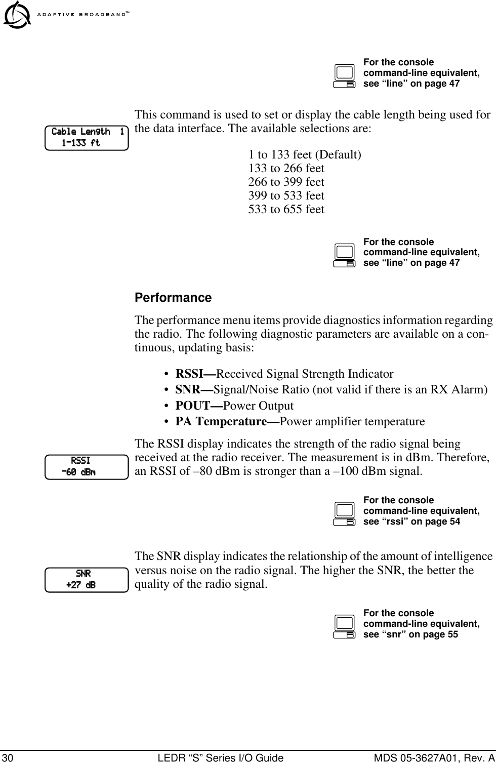
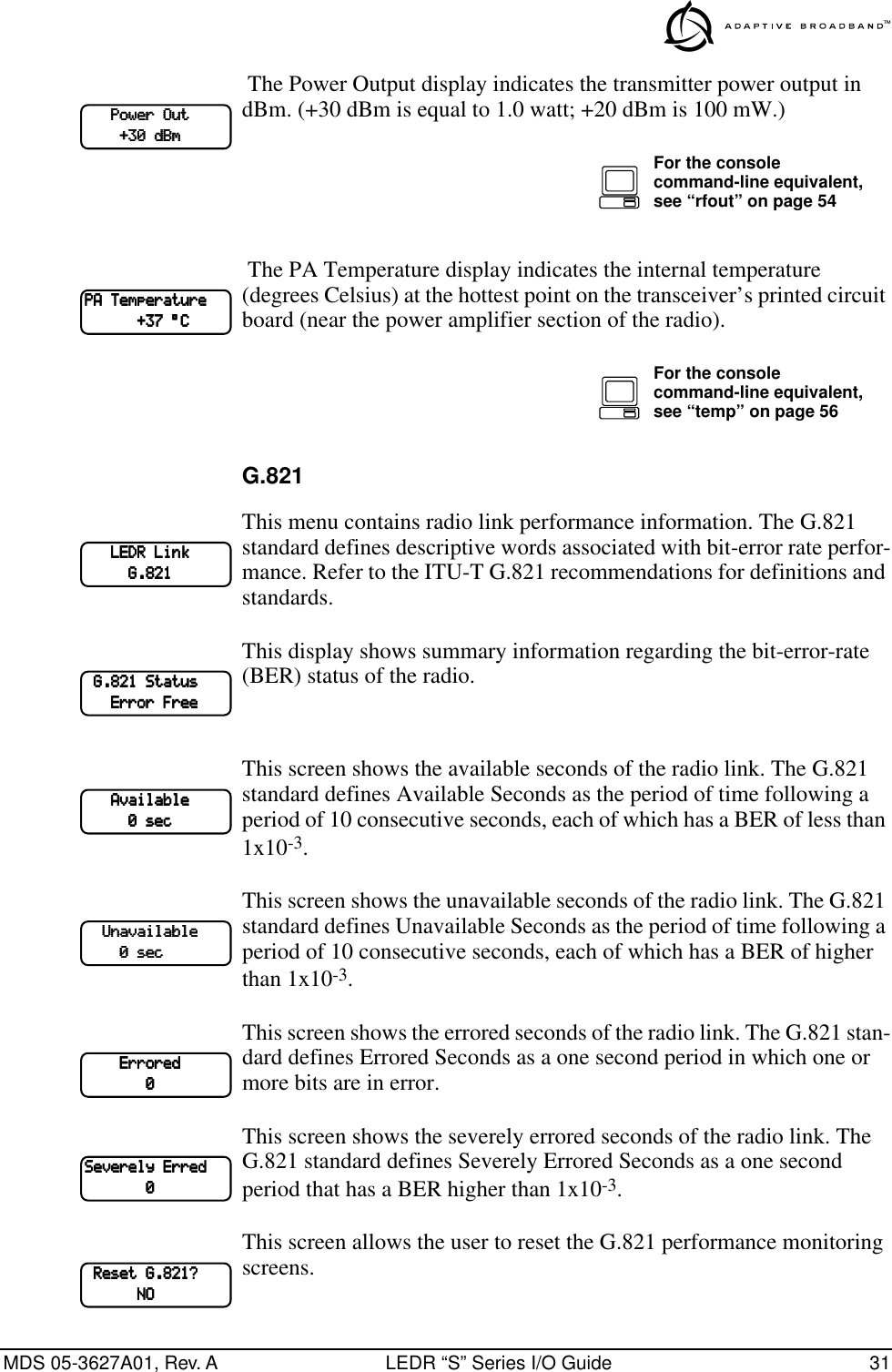
![54 LEDR “S” Series I/O Guide MDS 05-3627A01, Rev. Areprogram Usage: reprogram [subcommand] [<argument>]Subcommands: serial [type] [length] [<offset>]network [filename] [hostIP]statusThis write command reprograms the radio application software using Trivial File Transfer Protocol (TFTP). A TFTP server must be running on the network and properly configured to serve the necessary file(s).rfocal Usage: rfocal <freq region#> <cal-point#>This command starts the RFOUT Calibration Sequence. Example entry: rfocal 0 0.Example response:Region 0Index 0, Rfout = 18 dbm, Gain = 17Index 1, Rfout = 20 dbm, Gain = 28Index 2, Rfout = 22 dbm, Gain = 47Index 3, Rfout = 25 dbm, Gain = 79Index 4, Rfout = 27 dbm, Gain = 110Index 5, Rfout = 30 dbm, Gain = 170Index 6, Rfout = 32 dbm, Gain = 210rfout Usage: rfoutThis command displays the transmitter RF power output in dBm. See “Watts dBm Volts conversion” on page 92.rlogin Usage: [<toUnitID>[<UserName>]The rlogin command is used to login to the remote radio via the console.route The route command is used to add, delete or modify the IP routing table entries.Example resp: Destination Next Hop Net Mask Interface0.0.0.0 0.0.0.0 0.0.0.0 ETH10.0.0.0 10.2.142.143 255.255.0.0 ETH10.2.0.0 10.2.142.143 255.255.0.0 ETH10.2.142.144 10.2.142.143 255.255.255.255 AIR127.0.0.1 10.2.142.143 255.255.255.255 LPBKrssi Usage: rssiThis command displays the received signal strength indication in dBm.rssical Usage: rssical <freq region#> <cal-point#>This command starts the RSSI Calibration Sequence. Example entry: rssical 0 0.Example response:](https://usermanual.wiki/GE-MDS/LEDR400S.Exhibit-22-LEDR-400S-Users-Manual/User-Guide-117319-Page-60.png)
![MDS 05-3627A01, Rev. A LEDR “S” Series I/O Guide 55Region 0Index 0, RSSI = –110 dbm, Gain = –104Index 1, RSSI = –90 dbm, Gain = –40Index 2, RSSI = –75 dbm, Gain = +1Index 3, RSSI = –60 dbm, Gain = +28Index 4, RSSI = –45 dbm, Gain = +61Index 5, RSSI = –30 dbm, Gain = +97rxlock Usage: rxlockThis command displays the current modem lock status.Example response: rxlock: Modem is lockedsabytes Usage: sabytes [linelist] [bytes <bytelist]This command is used to set or display SA bytes in E1 multiframing. The [linelist] variable represents a list of line interfaces. It can consist of a single line number or linename, a comma separated list of line num-bers or linenames, a range of line numbers (i.e., 1–4), or if linelist is not given all lines. See Table 13 on page 44 for a list of line numbers.The bytelist variable consists 5 hex bytes (i.e., 3c) representing SA[4-8]. To keep a bytes present value when modifying higher bytes (i.e., modi-fying SA[7] only) use a * character in the respective byte position. Example: sabytes 1 bytes *,*,*,3c changes only SA[7] for line 1 to 3c.sernum Usage: sernumThis command displays the serial number of the radio. The number dis-played with this command matches the serial number printed on the serial number sticker on the radio chassis.snmpcomm Usage: [<read|write|trap>][<string>]This command is used to set or display SNMP community names.Example response: snmpcomm {read}: publicsnmpcomm {write}: privatesnmpcomm {trap}: publicsnr Usage: snrThis command displays the signal-to-noise ratio (SNR) of the received signal in dB. The SNR is an indication of the quality of the received signal. The higher this number, the higher the quality of the received signal. SNR readings are not valid when there is an RX Alarm.status Usage: statusThis command is used to display the performance and configuration data.Example response:](https://usermanual.wiki/GE-MDS/LEDR400S.Exhibit-22-LEDR-400S-Users-Manual/User-Guide-117319-Page-61.png)
![56 LEDR “S” Series I/O Guide MDS 05-3627A01, Rev. Astatus {Tx Freq}: 438075000status {Rx Freq}: 428075000status {Bandwidth}: 100 kHzstatus {Data Rate}: 256 kbpsstatus {Clock Mode}: internal, remote, Line1, Line2, Line3, Line4status {RSSI}: –100 dBmstatus {SNR}: 0 dBstatus {Rx Lock}: Unlockedstatus {Tx RF Out}: 18.0 dBmstatus {Temp}: 37 Degrees Csvch Usage: svch [subcommand] [<argument>]Subcommands: baud [300|1200|2400|4800|9600|19200|38400]csize [5–8]parity [none|even|odd]stop [0–2]This command sets or displays the service channel settings.telnetd [kill <session>]This command is used to display or kill (terminate) the telnet session(s).Ex. resp: Session Username Rem. Addr. Connectedtns0 ENGR 10.2.129.22 07/01/1999@ 13:57:17temp This command displays the radio’s power amplifier (PA) temperature.Example response: temp: 35 Degrees C (PA Temperature)test Usage: test [<0–n>|<testname>]This command starts a self-test function of the radio. There are several separate tests that can be run individually by specifying the test number after the command. The internal self tests are listed in Table 16.Table 16. Internal self tests Description TestNumber Test Name Flash memory test 0 flashDRAM memory test 1 dramConfiguration test 2 configBattery test 3 battAtod test 4 atodTransmitter phase locked loop test 5 txpllReceiver phase locked loop test 6 rxpllReal Time Clock test 7 rtcFPGA logic test 8 fpgaDSP test 9 dspCODEC test 10 codec](https://usermanual.wiki/GE-MDS/LEDR400S.Exhibit-22-LEDR-400S-Users-Manual/User-Guide-117319-Page-62.png)
![MDS 05-3627A01, Rev. A LEDR “S” Series I/O Guide 57threshold Usage: [<threshold>] [<level>]This command sets or displays the performance degradation threshold(s) of the LEDR radio.Example response: threshold {MinRssi}: 0threshold {MinSNR}: 0threshold {MaxTemp}: 70threshold {Max15ErrSec}: 900threshold {Max15SevereErrSec}: 900threshold {Max24ErrSec}: 86400threshold {Max24SevereErrSec: 86400time Usage: time [HH:MM[:SS]This command displays or sets the time of the radio’s internal real-time clock. The radio’s real time clock operates from an internal lithium bat-tery so it is running even if the radio has no DC power connected.The real time clock is fully compliant with year 2000 standards.timeslot Usage 1: timeslot [-d] [slotlist]Usage 2: timeslot -cThis command has two uses; In usage 1, the timeslots can be set or dis-played. In usage 2, all pending timeslots are committed.Modifications to the timeslot list are kept pending until all available slots have been assigned. The user can choose to commit slots when the last available slot is added to the pending list or by using the -c option. (See Usage 2.)The default action is to enable given timeslots. If no arguments are entered, the currently active timeslots and pending timeslots are dis-played.The slotlist variable is a list of timeslots and can be a single slot number, comma separated list of slot numbers, or a range of slot numbers (i.e., 2-8). Timeslots can be entered in any order and are automatically con-figured. Extra slots will be ignored. Unassigned timeslots in the pending list are signified by MA (must assign).Options:–d Disable timeslot(s)–c Commit pending timeslotsNOTE: T1 timeslots are 1–24. E1 timeslots are 0–31.](https://usermanual.wiki/GE-MDS/LEDR400S.Exhibit-22-LEDR-400S-Users-Manual/User-Guide-117319-Page-63.png)
![58 LEDR “S” Series I/O Guide MDS 05-3627A01, Rev. Atrapfilter Usage: trapfilter [<critical|major|minor|inform>]This command sets or displays which events cause SNMP traps.trapmgr [<1-5>] [<IP address>]This command sets or displays the trap manager IP addresses.Example response: trapmgr: 1 = 10.2.129.22trapmgr: 2 = 0.0.0.0trapmgr: 3 = 0.0.0.0trapmgr: 4 = 0.0.0.0trapmgr: 5 = 10.2.129.1trend Usage: trendThis command is used to display continuously updated readings of: RSSI, radio temperature, RF output, signal-to-noise ratio, and FEC errors (correc ted and uncorrected). The display can be stopped by pressing Control-C on the terminal.txkey Usage: txkey [on|off]This command sets or displays the transmitter status. ON indicates the radio is keyed and transmitting. OFF indicates the transmitter is not keyed and is not transmitting. unitid Usage: unitid [<ID>]This command sets or displays the radio’s unit identification number. This number is used for Orderwire signaling and the EMS (Element Management System). uptime Usage: uptime This command displays how long the radio has been powered-on.user Usage: user [subcommand] [<argument>]Subcommands: add <user> <pass> <perm>del <user>perm <user> <perm>passThis command provides administrator access for setting new user accounts and permission levels. The password (pass) and user names are case sensitive and may not exceed eight characters. The characters \\ may be used as a “blank” pass-word.User permission (perm) may be set to: read (r), write (w), network (n) or administrator (a). The privileges granted by each level are as follows:• Read (r) is the lowest level of user access and allows radio informa-tion to be viewed only. Changes to radio settings are not allowed.](https://usermanual.wiki/GE-MDS/LEDR400S.Exhibit-22-LEDR-400S-Users-Manual/User-Guide-117319-Page-64.png)
![MDS 05-3627A01, Rev. A LEDR “S” Series I/O Guide 59• Write (w) allows most, but not all radio settings to be changed.• Network (n) allows everything permitted by lower levels, and also allows changes to the radio’s IP configuration.• Administrator (a) allows everything permitted in lower levels, and also allows changes to be made to user accounts (add, delete, mod-ify). It is normally used by a System Administrator or other person responsible for the radio system.Example entry: user add John <password> wThe above example shows the command string for adding a new user (John), with “write” permission.Example response: user: Command CompleteNOTE: If you are logging in for the first time since the radio wasshipped from the factory, refer to page 16 for important logininformation.ver Usage: ver [frw|hdw|ext]This command displays radio version information for firmware (frw), hardware (hdw) and Extended Version Information (ext).Example response: ver: ADAP Part #06-3451A01ver: 1.0.0volume <volume>This command sets or displays the orderwire handset volume.Example response: volume: 100vox <vox threshold>The vox command sets or displays the orderwire vox (voice-operated transmit) threshold.Example response: vox: 5who Usage: whoThis command displays users currently logged in to the radio operating system.3.5 SNMP Network ManagementSimple Network Management Protocol (SNMP) offers a comprehensive solution to network management. It allows full configuration, perfor-mance monitoring, fault diagnosis and security administration of an entire LEDR radio network.](https://usermanual.wiki/GE-MDS/LEDR400S.Exhibit-22-LEDR-400S-Users-Manual/User-Guide-117319-Page-65.png)
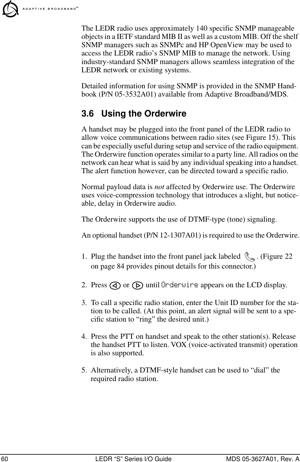
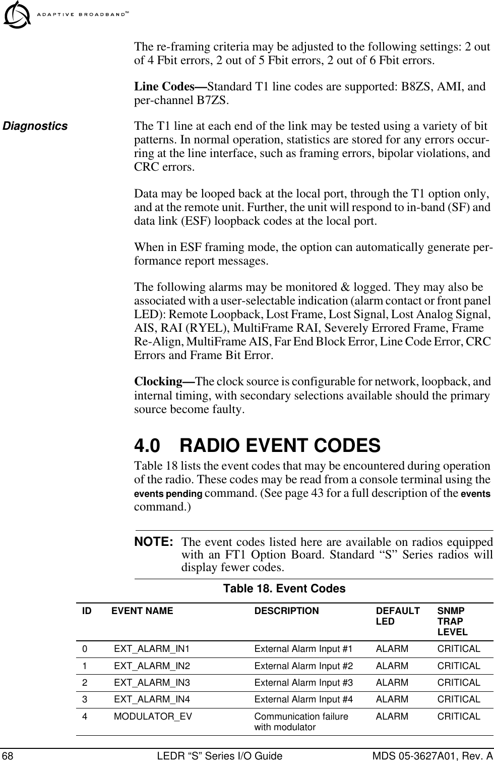
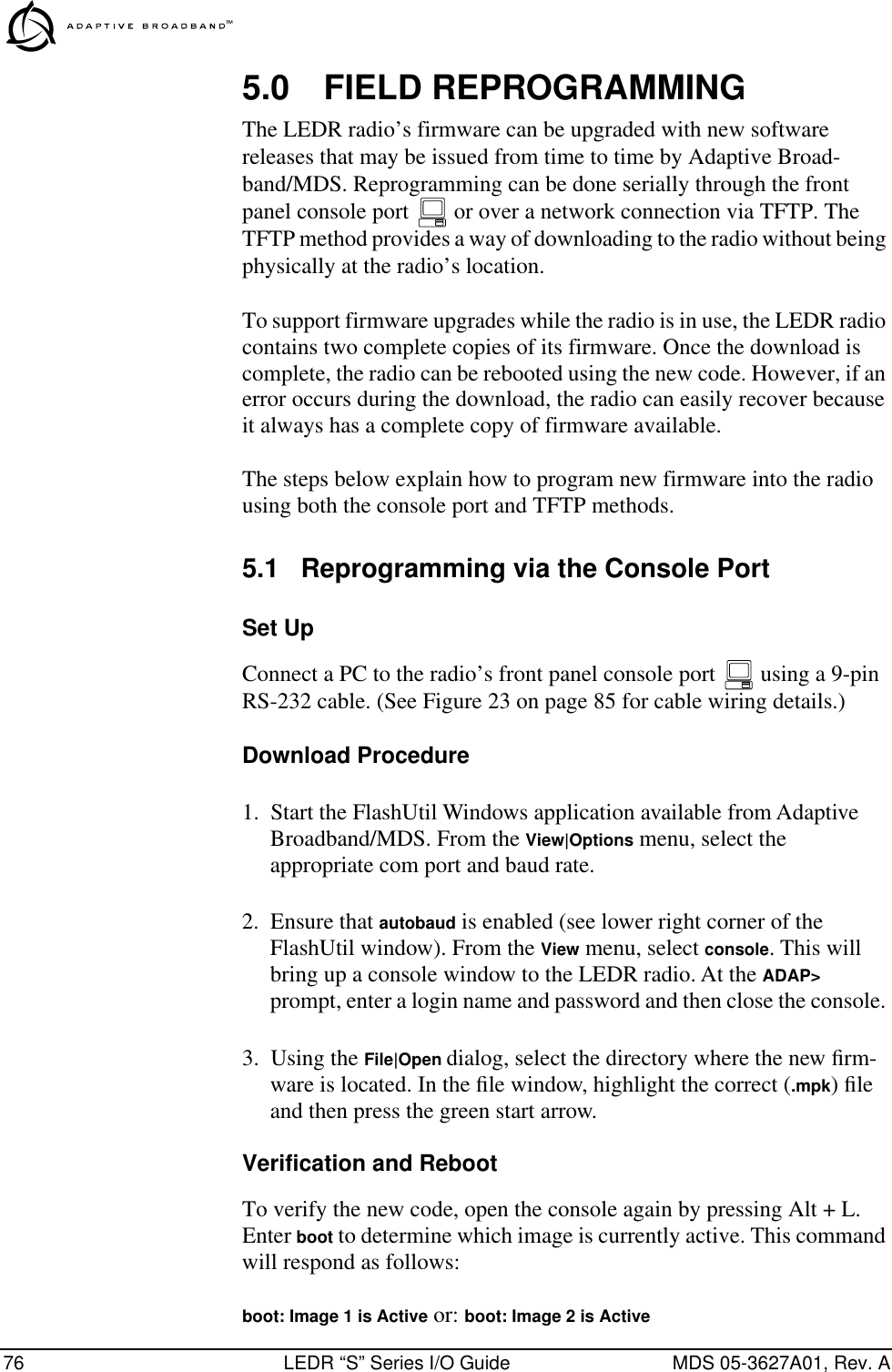
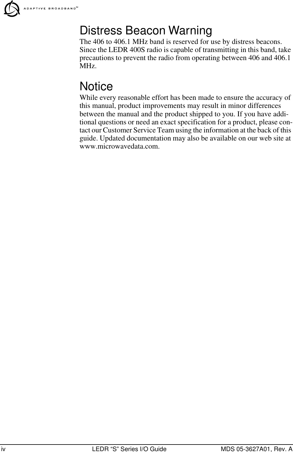
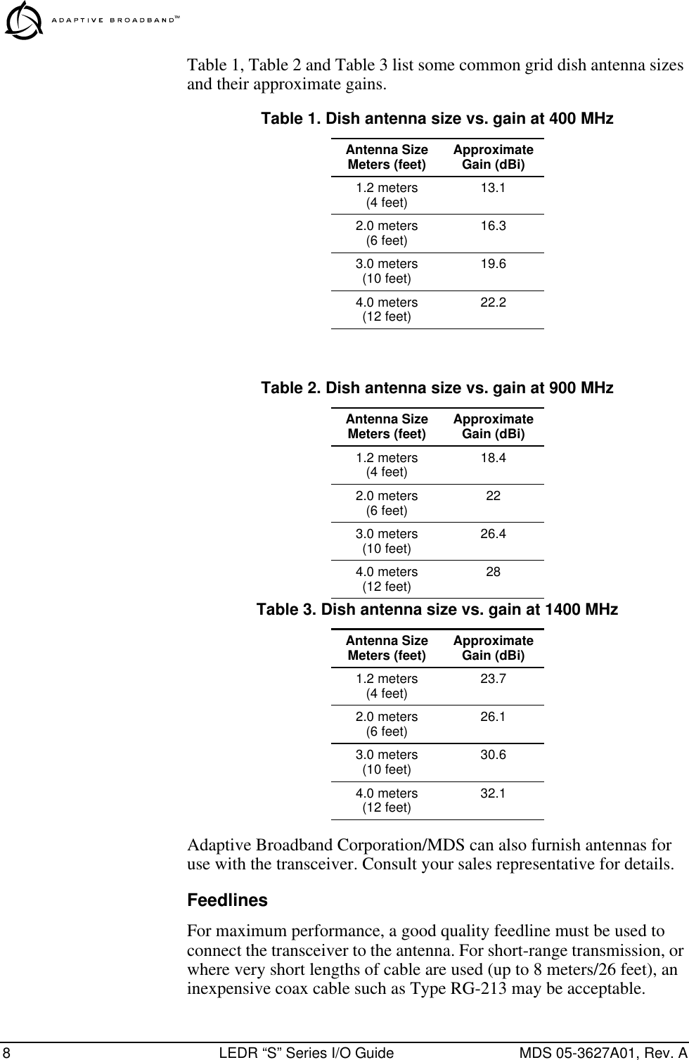
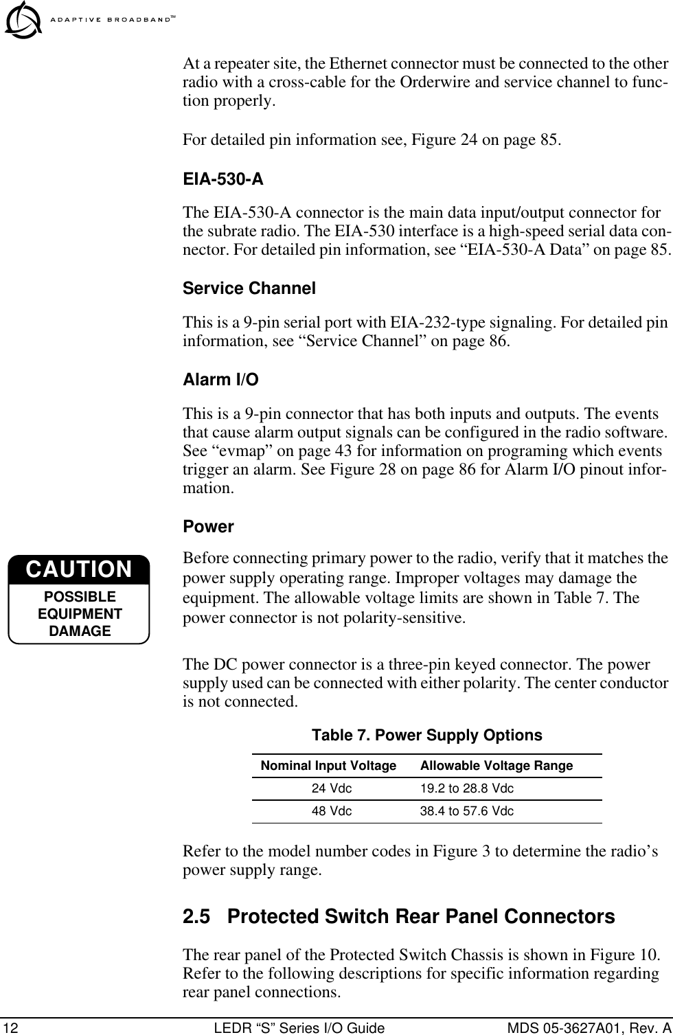
![MDS 05-3627A01, Rev. A LEDR “S” Series I/O Guide 77The new firmware is downloaded into the inactive image. Therefore, if the radio responded Image 1 is Active, enter iverify 2, otherwise, enter iverify 1. The radio will respond indicating whether or not the image has been verified. If the image does not verify, try downloading the code again. If the download fails after repeated attempts, the hardware may be damaged. For a replacement board please contact the factory using the information given at the back of this manual.NOTE: The following paragraph describes rebooting the radio. Thisaction will disrupt the communications link.Once the image has been verified, the radio must be rebooted using the new firmware. This is done by entering the command boot 1 or boot 2, where the 1 or 2 corresponds with the image number used with the iverify command above.Once the radio has rebooted and displays the ADAP> prompt again, the firmware can be downloaded or copied into the other image. Often, copying the firmware from one image to the other can be faster than per-forming a second download. To copy the firmware over to the other image, simply enter icopy. The radio will prompt you for confirmation (y/n) and then begin copying.5.2 Reprogramming via a Network ConnectionSet UpConnect the LEDR radio’s ETHERNET NMS connector to a PC via a net-work connection This can be done in one of three ways: 1) by con-necting both the radio and the PC to a network hub, 2) by connecting them directly through an ethernet cross-over cable, or 3) by connecting them to a common LAN.If the radio is near the PC, an RS-232 cable can be connected between them in order to run the console commands. However, if the radio is some distance away, such as at a remote site, telnet or rlogin can be used to execute the necessary commands.Download Procedure1. Log in to the radio using the login command. Use the ip command to ensure that the radio has a valid IP address. 2. "Ping" the radio from the PC to ensure that the PC and the radio have valid routes to pass information between them.3. Start a TFTP server application on the PC. At the radio’s ADAP> prompt, start the download by entering reprogram network [filename] [PC’s IP Address]. The download can be monitored from the radio by](https://usermanual.wiki/GE-MDS/LEDR400S.Exhibit-22-LEDR-400S-Users-Manual/User-Guide-117319-Page-83.png)