GE MDS LEDR400S LEDR Microwave Radio User Manual 3627A LEDR S body
GE MDS LLC LEDR Microwave Radio 3627A LEDR S body
GE MDS >
Contents
- 1. Exhibit 22 LEDR 400S Users Manual
- 2. LEDR 400S Users Manual Addendum
Exhibit 22 LEDR 400S Users Manual
Installation and Operation Guide
MDS 05-3627A01, Rev. A
MARCH 2000
Digital Microwave Radio
LEDR Subrate Series
Covers LEDR 400S, 900S and 1400S
(plus optional fractional interface)

QUICK START GUIDE
Below are the basic steps for installing the LEDR radio. When making cable connections, refer
to page 10 for a rear panel view of the radio.
1. Install and connect the antenna system to the radio
• Ensure a path study has been conducted and that the radio path is acceptable.
• Use good quality, low loss coaxial cable. Keep the feedline as short as possible.
• Preset directional antennas in the direction of desired transmission/reception.
2. Connect the data equipment to appropriate rear panel connector
• For standard “S” Series radios, see Figure 25.
• For radios equipped with an FT1 Option Board, see Figure 26.
• Verify the data equipment is configured as DTE. (By default, the radio is configured as DCE.)
3. Apply DC power to the radio
• Verify that the voltage matches the power supply operating range (24 Vdc or 48 Vdc).
• The power connector is a three-pin keyed connector. The power source can be connected with
either polarity. The center conductor is
not
connected.
4. Set the radio’s basic configuration using front panel or Console interface
• You must first login with a valid username and password (see page 16).
• Set the transmit/receive frequencies (
TX xxx.xxxx
/
RX xxx.xxxx
).
• Refer to this manual for other configuration settings.
5. Verify proper operation by observing the LED display
• Refer to “LEDs” on page 19 for a description of the status LEDs.
• Aim directional antenna for maximum receive signal strength using the
RSSI
Screen.
6. Configure the Simple Network Management Protocol (SNMP) MIB, if used
• Refer to the SNMP Handbook (Part No. 05-3532A01).

MDS 05-3627A01, Rev. A LEDR “S” Series I/O Guide i
TABLE OF CONTENTS
1.0 INTRODUCTION ......................................................................... 1
1.1 Product Description ..........................................................................1
LEDR Features...............................................................................1
Typical Applications........................................................................2
1.2 Model Number Codes ......................................................................3
2.0 INSTALLATION............................................................................ 4
2.1 General Requirements .....................................................................4
Site Selection .................................................................................5
Terrain and Signal Strength............................................................5
On-the-Air Test ...............................................................................6
A Word About Interference .............................................................6
2.2 Antenna and Feedline Selection ......................................................7
Antennas ........................................................................................7
Feedlines........................................................................................8
2.3 Radio Mounting ................................................................................9
Attaching the Rack Brackets ........................................................10
2.4 Radio Rear Panel Connectors .......................................................10
Ground Stud.................................................................................11
Antenna/TX ..................................................................................11
RX ................................................................................................11
G.703 Data Connectors (4)—For radios with FT1 Option Bd.......11
Ethernet........................................................................................11
EIA-530-A.....................................................................................12
Service Channel...........................................................................12
Alarm I/O ......................................................................................12
Power ...........................................................................................12
2.5 Protected Switch Rear Panel Connectors ......................................12
RxA...............................................................................................13
RxB...............................................................................................13
Antenna........................................................................................13
TxA...............................................................................................13
TxB...............................................................................................13
Protected Data .............................................................................13
E1.................................................................................................13
Ethernet........................................................................................14
530 (A&B).....................................................................................14
EIA-530-A.....................................................................................14
Service Channel...........................................................................14
2.6 Inter-Unit Cabling for Protected Stations ........................................14
3.0 OPERATION.............................................................................. 15

ii LEDR “S” Series I/O Guide MDS 05-3627A01, Rev. A
3.1 Initial Startup ..................................................................................15
Maximizing RSSI..........................................................................16
Initial Login—Required to change radio settings..........................16
3.2 Communicating with the Radio ......................................................18
Front Panel Controls.....................................................................18
Front Panel Menu Tree .................................................................20
3.3 Front Panel LCD Menu Descriptions ..............................................24
Default Parameters.......................................................................24
Login.............................................................................................24
Network ........................................................................................24
General.........................................................................................25
RF Configuration ..........................................................................26
IO Configuration ...........................................................................27
Line Configuration ........................................................................28
Performance.................................................................................30
G.821............................................................................................31
Modem .........................................................................................32
Console ........................................................................................32
Diagnostics...................................................................................33
Orderwire......................................................................................33
Front Panel ...................................................................................33
Redundant....................................................................................34
Remote Status..............................................................................35
3.4 Console Port .................................................................................35
Using the Console Port ................................................................36
Command Descriptions................................................................39
3.5 SNMP Network Management .........................................................59
3.6 Using the Orderwire .......................................................................60
3.7 Bandwidths, Data Rates and Modulation Types .............................61
3.8 Transmit Clock Selection ................................................................62
3.9 Protected (1+1) LEDR Radio .........................................................64
Protected Operation .....................................................................64
Space Diversity Operation............................................................66
User Interface & Control...............................................................67
3.10 Fractional T1 Interface Card (Optional Equipment) ......................67
Fractional T1 Performance ...........................................................67
4.0 RADIO EVENT CODES............................................................. 68
5.0 FIELD REPROGRAMMING....................................................... 76
5.1 Reprogramming via the Console Port ............................................76
Set Up ..........................................................................................76
Download Procedure....................................................................76
Verification and Reboot ................................................................76
5.2 Reprogramming via a Network Connection ...................................77
Set Up ..........................................................................................77
Download Procedure....................................................................77
Verification and Reboot ................................................................78

MDS 05-3627A01, Rev. A LEDR “S” Series I/O Guide iii
6.0 FIELD REPLACEABLE UNITS.................................................. 78
6.1 Field Installation of FT1 Option Board
Non-protected: 03-3846A01
Protected: 03-3539A01 ..........................................................................78
7.0 TECHNICAL REFERENCE ....................................................... 82
7.1 Specifications .................................................................................82
7.2 Pinout Information ..........................................................................84
Orderwire......................................................................................84
Console ........................................................................................85
Ethernet........................................................................................85
EIA-530-A Data ............................................................................85
G.703 Data Connectors (4 on rear panel)....................................86
Service Channel...........................................................................86
Alarm............................................................................................86
7.3 RF Propagation Planning ...............................................................87
Fresnel Zone Clearance...............................................................87
Earth Curvature............................................................................88
Fade Margins ...............................................................................88
Free Space Path Loss..................................................................89
Parabolic Antenna Gain ...............................................................89
Fresnel Zone Boundary................................................................89
Parabolic Antenna Beamwidth .....................................................89
Theoretical Signal Strength..........................................................90
Probability of System Fading........................................................90
7.4 Bench Testing of Radios .................................................................90
7.5 Watts dBm Volts conversion ...........................................................92
Copyright Notice
This Installation and Operation Guide and all software described herein
are protected by
copyright: 2000
Adaptive Broadband Corporation,
Inc. All rights reserved.
Adaptive Broadband Corporation reserves its right to correct any errors
and omissions.
Operational Safety Notice
The radio equipment described in this guide emits radio frequency
energy. Although the power level is low, the concentrated energy from
a directional antenna may pose a health hazard. Do not allow people to
come in close proximity to the front of the antenna when the transmitter
is operating.
This manual is intended to guide a professional installer to install,
operate and perform basic system maintenance on the described radio.
RF Exposure

iv LEDR “S” Series I/O Guide MDS 05-3627A01, Rev. A
Distress Beacon Warning
The 406 to 406.1 MHz band is reserved for use by distress beacons.
Since the LEDR 400S radio is capable of transmitting in this band, take
precautions to prevent the radio from operating between 406 and 406.1
MHz.
Notice
While every reasonable effort has been made to ensure the accuracy of
this manual, product improvements may result in minor differences
between the manual and the product shipped to you. If you have addi-
tional questions or need an exact specification for a product, please con-
tact our Customer Service Team using the information at the back of this
guide. Updated documentation may also be available on our web site at
www.microwavedata.com.

MDS 05-3627A01, Rev. A LEDR “S” Series I/O Guide 1
1.0 INTRODUCTION
This manual is intended to help an experienced technician install, con-
figure, and operate a LEDR 400S, 900S or 1400S digital radio. It begins
with an overall description of radio features and is followed by the steps
required to mount a LEDR radio and place it into normal operation.
After installation, we suggest keeping this guide near the radio for future
reference.
1.1 Product Description
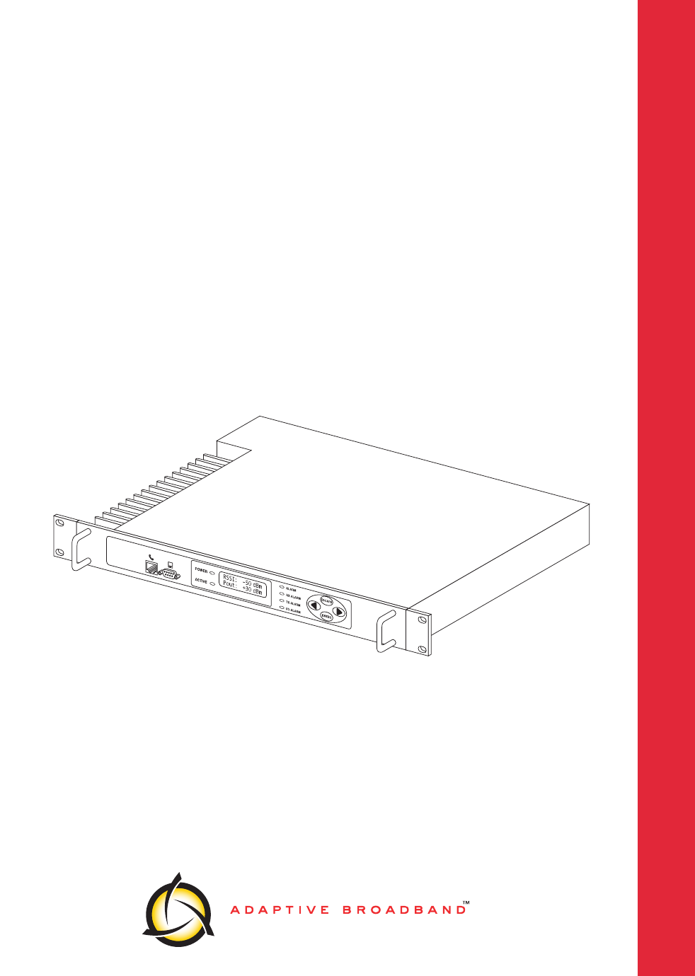
The LEDR radio (Figure 1) is a full duplex, point-to-point digital unit
operating in the 330-512 MHz frequency band (model 400S), 800-960
(model 900S) or 1350–1535 MHz frequency band (model 1400S) with
bandwidths ranging from 25 kHz to 200 kHz, depending on the radio
model and installed options. The LEDR radio is designed to connect to
industry-standard EIA-530 data interface equipment.
With the addition of a fractional T1 card option, the radio can be con-
nected to industry-standard G.703 T1 data interface equipment. See
page 67 for a complete description of the fractional T1 option.
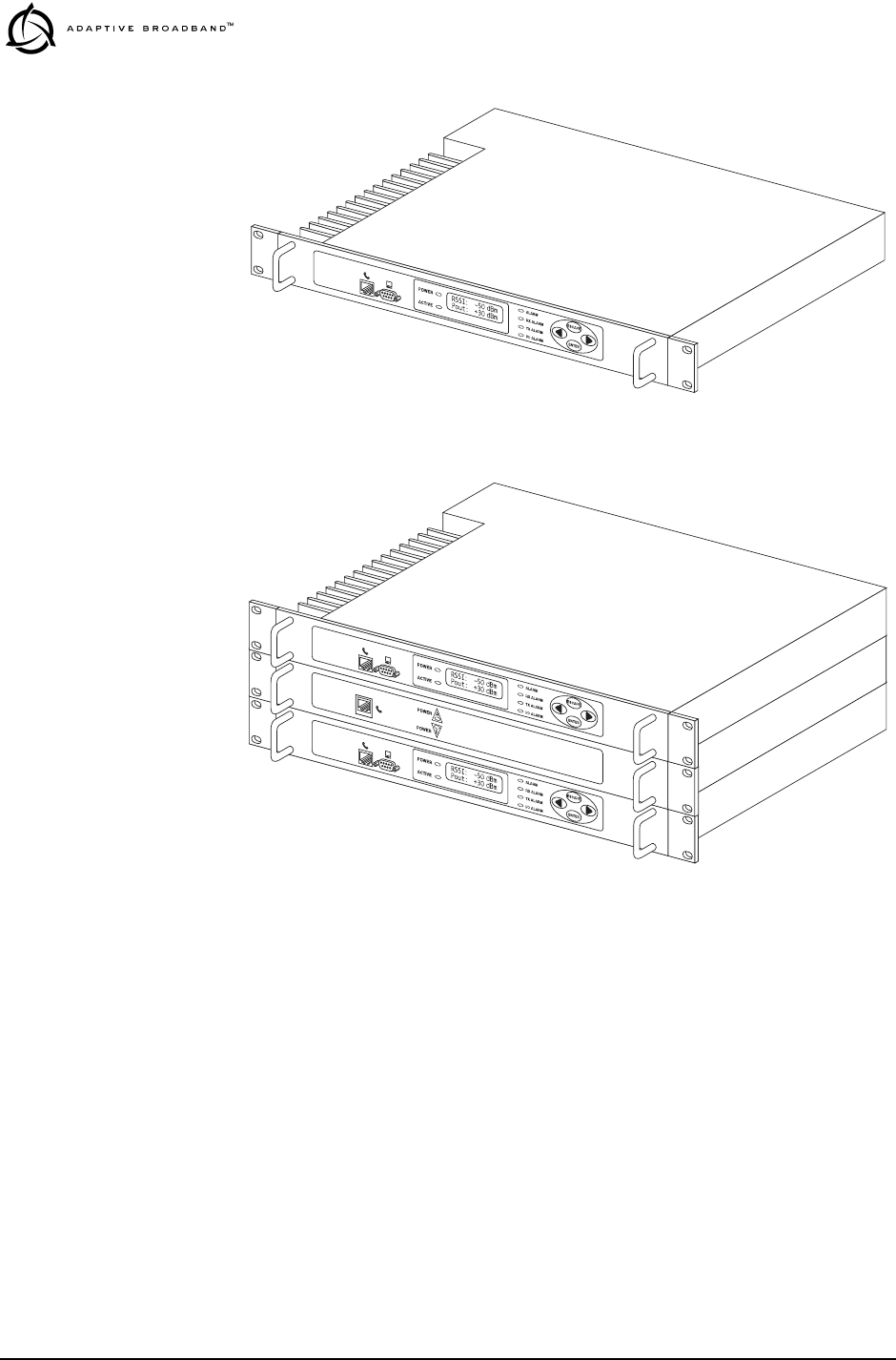
The radio is also available as a protected “1+1” version (Figure 2) con-
sisting of two identical LEDR radios and a Protected Switch Chassis.
The protected version is designed to perform automatic switchover to a
second radio in the event of a failure in the primary unit. See page 64 for
detailed information on the protected version.
LEDR Features
• 64, 128, 256, 384, 512 and 768 kbps data rates
• n x 64 kbps data rates for units with an FT1 Option Board
• Network Management via SNMP version 1
• Protected operation (1+1) compatible
• 1.0 watt transmit power
• Rack space efficient (1RU) size
• Rugged, reliable design
• Voice Orderwire (DTMF compliant)
• Data service channel
2 LEDR “S” Series I/O Guide MDS 05-3627A01, Rev. A
Invisible place holder
Figure 1. The LEDR Digital Radio (Non-Protected Version)
Invisible place holder
Figure 2. LEDR Digital Radio (Protected Version)
Typical Applications
• Point-to-point transmission applications
• Cost effective, “thin route” applications
• Long haul telecommunications links
• Cellular backhaul
• Last mile links
• Trunked radio links
• SCADA systems
MDS 05-3627A01, Rev. A LEDR “S” Series I/O Guide 3
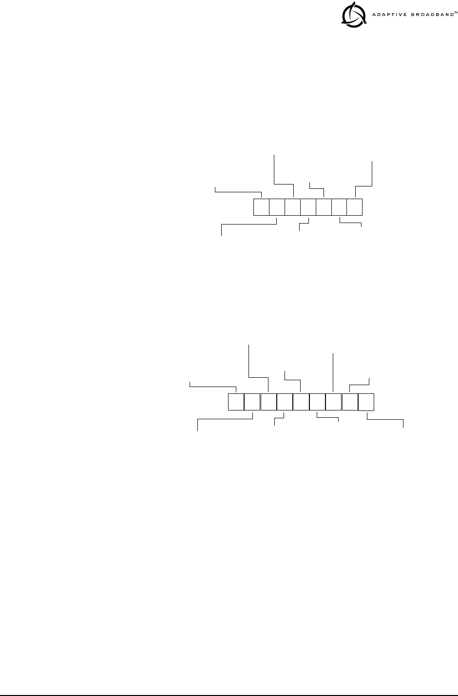
1.2 Model Number Codes
The radio model number is printed on the serial number tag, which is
affixed to the chassis. Figure 3, Figure 4 and Figure 5 show the signifi-
cance of the model number string on the various LEDR “S” models.
Contact the factory for specific information on optional configurations.
Invisible place holder
Figure 3. Model Number Codes (LEDR 400S)
Invisible place holder
Figure 4. Model Number Codes (LEDR 900S)
MODEL NUMBER
CODES ARE SUBJECT
TO CHANGE.
DO NOT USE FOR
PRODUCT ORDERING. 400S
MODES
DUPLEXER SEP.
INPUT POWER
1= 24 Vdc
BANDWIDTH
E= 500 kHz
SPLITTER
PROTECTED STBY
2= Non-protected Fractional E1/T1 N= None
A= Asymmetric 1dB/10 dB
1= Internal (300-400 MHz)
2= 48 Vdc
F= 1 MHz
G= 2 MHz
N= None
REGULATORY
N= Not applicable
E= ETS 300630/
5= 1+1 Fractional E1/T1
8= Space Diversity E1/T1
2= Internal-(400-512 MHz)
S= Symmetric 3dB
W= Warm
H= Hot
ETS 300385/MPT1717
3= Int.-Space Div. (300-400 MHz)
4= Int.-Space Div. (400-512 MHz)
900S
MODES
N= Non-protected (EIA-530)
DUPLEXER SEP.
INPUT POWER
1= 24 Vdc
BANDWIDTH
A= 25 kHz
RECEIVE FREQ.
TRANSMIT FREQ.
TRANSMIT
NMS SUPPORT
S= Standard
1= Non-protected (G.703)
2= Protected (EIA-530)
3= Protected (G.703)
2= 860-900 MHz
1= 800-860 MHz
N= None (external)
1= 9 MHz
2= 48 Vdc
3= 900-960 MHz
B= 50 kHz
C= 100 kHz
D= 200 kHz
2= 860-900 MHz
1= 800-860 MHz
3= 900-960 MHz
H= High
L= Low
1= SNMP
REGULATORY
N= Not applicable
A= FCC/IC/CSA
4 LEDR “S” Series I/O Guide MDS 05-3627A01, Rev. A
Invisible place holder
Figure 5. Model Number Codes (LEDR 1400S)
2.0 INSTALLATION
Installation of the LEDR transceiver is not difficult, but it does require
some planning to ensure optimal efficiency and reliability. This section
provides tips for selecting an appropriate site, choosing antennas and
feedlines, and minimizing the chance of interference. This material
should be reviewed before beginning equipment installation.
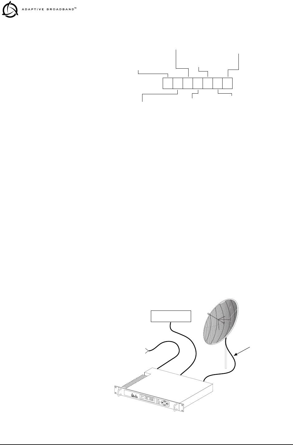
2.1 General Requirements
There are four main requirements for installing the transceiver—a suit-
able installation environment, adequate and stable primary power, a
good antenna system, and the correct interface between the transceiver
and the external data equipment. Figure 6 shows a typical station
arrangement.
Invisible place holder
Figure 6. Typical Station Arrangement
1400S
MODES
DUPLEXER SEP.
INPUT POWER
1= 24 Vdc
BANDWIDTH
E= 500 kHz
SPLITTER
PROTECTED STBY
2= Non-protected Fractional E1/T1 N= None
A= Asymmetric 1dB/10 dB
N= None (Optional Ext.)
2= 48 Vdc
F= 1 MHz
G= 2 MHz
N= None
REGULATORY
N= Not applicable
E= ETS 300630/
5= 1+1 Fractional E1/T1
8= Space Diversity E1/T1
R= None (Wired for Ext.) Redun.
S= Symmetric 3dB
W= Warm
H= Hot
ETS 300385/MPT1717
1= Internal
2= Internal-Space Diversity
GRID DISH
ANTENNA
LOW LOSS
COAXIAL CABLE
TO DC
POWER SOURCE
(24 or 48 Vdc as appropriate)
DATA INTERFACE

MDS 05-3627A01, Rev. A LEDR “S” Series I/O Guide 5
Site Selection
For a successful installation, careful thought must be given to selecting
proper sites for the radios and antenna systems. Suitable sites should
offer:
• An antenna location that provides an unobstructed path in the
direction of the associated station
• A source of adequate and stable primary power
• Suitable entrances for antenna, interface or other required
cabling
• Adequate clearance around the radio for ventilation
These requirements can be quickly determined in most cases. A possible
exception is the first item—verifying that an unobstructed transmission
path exists. Microwave radio signals travel primarily by line-of-sight,
and obstructions between the sending and receiving stations will affect
system performance. This is especially important for the LEDR 1400S,
which operates in the 1400 MHz microwave frequency band.
If you are not familiar with the effects of terrain and other obstructions
on radio transmission, the following discussion will provide helpful
background.
Terrain and Signal Strength
A line-of-sight path between stations is highly desirable, and provides
the most reliable communications link in all cases. A line-of-sight path
can often be achieved by mounting each station antenna on a tower or
other elevated structure that raises it to a level sufficient to clear sur-
rounding terrain and other obstructions.
The requirement for a clear transmission path depends upon the distance
to be covered by the system. If the system is to cover only a limited dis-
tance, say 5 km (3.1 miles), then some obstructions in the transmission
path may be tolerable. For longer-range systems, any obstruction could
compromise the performance of the system, or block transmission
entirely.
The signal strength at the receiver must exceed the receiver sensitivity
by an amount known as the fade margin to provide reliable operation
under various conditions.
Detailed information on path planning should be reviewed before begin-
ning an installation. See RF Propagation Planning on page 87 for more
information. Computer software is also available for this purpose that
can greatly simplify the steps involved in planning a path.

6 LEDR “S” Series I/O Guide MDS 05-3627A01, Rev. A
Adaptive Broadband/MDS offers path analysis (for paths in the USA)
as an engineering service. Contact the factory for additional informa-
tion.
On-the-Air Test
If you’ve analyzed the proposed transmission path and feel that it is
acceptable, an on-the-air test of the equipment and path should be con-
ducted. This not only verifies the path study results, but allows you to
see firsthand the factors involved at each installation site.
The test can be performed by installing a radio at each end of the pro-
posed link and checking the Received Signal Strength Indication (RSSI)
value reported at the front panel LCD screen of each radio. If adequate
signal strength cannot be obtained, it may be necessary to mount the sta-
tion antennas higher, use higher gain antennas, or select a different site
for one or both stations.
A Word About Interference
Interference is possible in any radio system. However, since the LEDR
radio is designed for use in a licensed system, interference is less likely
because frequency allocations are normally coordinated with consider-
ation given to geographic location and existing operating frequencies.
The risk of interference can be further reduced through prudent system
design and configuration. Allow adequate separation between frequen-
cies and radio systems.
C/I Curves
A carrier to interference (C/I) curve can help in frequency and space
coordination. The information in this curve can aid greatly in helping
plan geographic locations and frequency usage for radio systems. Con-
tact the factory for additional information on carrier to interference
curves. A whitepaper on the subject is available on request. Ask for Pub-
lication No. 05-3638A01.
Keep the following points in mind when setting up your point-to-point
system:
1. Systems installed in lightly populated areas are least likely to
encounter interference; those in urban and suburban environments
are more likely to be affected by other devices operating in the
radio’s frequency band and adjacent services.
2. Directional antennas must be used at each end of a point-to-point
link. They confine the transmission and reception pattern to a com-
paratively narrow beam, which minimizes interference to and from
stations located outside the pattern. The larger the antenna, the more
focused the transmission and reception pattern and the higher the
gain.

MDS 05-3627A01, Rev. A LEDR “S” Series I/O Guide 7
3. If interference is suspected from another system, it may be helpful
to use antenna polarization that is opposite to the interfering sys-
tem’s antennas. An additional 20 dB (or more) of attenuation to
interference can be achieved by using opposite antenna polarization.
Refer to the antenna manufacturer’s instructions for details on
changing polarization.
2.2 Antenna and Feedline Selection
Antennas
The antenna system is perhaps the most crucial part of the system
design. An antenna system that uses poor quality feedline, or is improp-
erly aligned with the companion site, will result in poor performance, or
no communication at all.
A directional antenna must be used for point-to-point systems to mini-
mize interference both to and from nearby systems. In general, cylin-
drical or dish type antennas with a parabolic reflector must be used. Yagi
or corner reflector types may be acceptable in some applications. Check
government regulations.
The exact style of antenna used depends on the size and layout of a
system. In most cases, a directional “dish” type of antenna is used with
the radio (Figure 7). Dish antennas maximize transmission efficiency
and restrict the radiation pattern to the desired transmission path.
Invisible place holder
Figure 7. Typical Grid Dish Antenna

8 LEDR “S” Series I/O Guide MDS 05-3627A01, Rev. A
Table 1, Table 2 and Table 3 list some common grid dish antenna sizes
and their approximate gains.
Adaptive Broadband Corporation/MDS can also furnish antennas for
use with the transceiver. Consult your sales representative for details.
Feedlines
For maximum performance, a good quality feedline must be used to
connect the transceiver to the antenna. For short-range transmission, or
where very short lengths of cable are used (up to 8 meters/26 feet), an
inexpensive coax cable such as Type RG-213 may be acceptable.
Table 1. Dish antenna size vs. gain at 400 MHz
Antenna Size
Meters (feet) Approximate
Gain (dBi)
1.2 meters
(4 feet) 13.1
2.0 meters
(6 feet) 16.3
3.0 meters
(10 feet) 19.6
4.0 meters
(12 feet) 22.2
Table 2. Dish antenna size vs. gain at 900 MHz
Antenna Size
Meters (feet) Approximate
Gain (dBi)
1.2 meters
(4 feet) 18.4
2.0 meters
(6 feet) 22
3.0 meters
(10 feet) 26.4
4.0 meters
(12 feet) 28
Table 3. Dish antenna size vs. gain at 1400 MHz
Antenna Size
Meters (feet) Approximate
Gain (dBi)
1.2 meters
(4 feet) 23.7
2.0 meters
(6 feet) 26.1
3.0 meters
(10 feet) 30.6
4.0 meters
(12 feet) 32.1

MDS 05-3627A01, Rev. A LEDR “S” Series I/O Guide 9
For longer cable runs, or for longer-range communication paths, we rec-
ommend using a low-loss cable suited for 1400 MHz, such as Andrew
Heliax
®
. Whichever type of cable is used, it should be kept as short as
possible to minimize signal loss.
Table 4, Table 5 and Table 6 list several types of acceptable feedlines
and the associated losses according to operating frequency.
Table 6 lists several types of acceptable feedlines and the associated
losses at 1400 MHz.
2.3 Radio Mounting
The radio can be mounted either in a 19-inch equipment rack or on a
table top. It should be located in a relatively clean, dust-free environ-
ment that allows easy access to the rear panel connectors as well as front
panel controls and indicators. Air must be allowed to pass freely over the
ventilation holes and heat sink on the side panel.
Table 4. Feedline Loss Table (450 MHz)
Cable Type 3.05 Meters
(10 Feet) 15.24 Meters
(50 Feet) 30.48 Meters
(100 Feet) 152.4 Meters
(500 Feet)
RG-8A/U 0.51 dB 2.53 dB 5.07 dB 25.35 dB
1/2 in. HELIAX 0.12 dB 0.76 dB 1.51 dB 7.55 dB
7/8 in. HELIAX 0.08 dB 0.42 dB 0.83 dB 4.15 dB
1-1/4 in. HELIAX 0.06 dB 0.31 dB 0.62 dB 3.10 dB
1-5/8 in. HELIAX 0.05 dB 0.26 dB 0.52 dB 2.60 dB
Table 5. Feedline Loss Table (960 MHz)
Cable Type 3.05 Meters
(10 Feet) 15.24 Meters
(50 Feet) 30.48 Meters
(100 Feet) 152.4 Meters
(500 Feet)
RG-8A/U 0.85 dB 4.27 dB 8.54 dB 42.70 dB
1/2 in. HELIAX 0.23 dB 1.15 dB 2.29 dB 11.45 dB
7/8 in. HELIAX 0.13 dB 0.64 dB 1.28 dB 6.40 dB
1-1/4 in. HELIAX 0.10 dB 0.48 dB 0.95 dB 4.75 dB
1-5/8 in. HELIAX 0.08 dB 0.40 dB 0.80 dB 4.00 dB
Table 6. Feedline Loss Table (1400 MHz)
Cable Type 8 Meters
(26 Feet) 15 Meters
(49 Feet) 30 Meters
(98 Feet) 61 Meters
(200 Feet)
RG-213 3.0 dB 6.03 dB 12.05 dB 24.1 dB
1/2 in. HELIAX 0.73 dB 1.47 dB 2.93 dB 5.9 dB
7/8 in. HELIAX 0.42 dB 0.83 dB 1.66 dB 3.32 dB
1-5/8 in. HELIAX 0.26 dB 0.26 dB 1.05 dB 2.1 dB
10 LEDR “S” Series I/O Guide MDS 05-3627A01, Rev. A
The dimensions of the LEDR radio are:
• 305 mm (12 in) deep
• 426 mm (16.75 in) wide—excluding rack brackets
• 45 mm (1.75 in) high—1RU
Attaching the Rack Brackets
The radio is normally shipped with the rack brackets uninstalled. To
attach them, select the desired mounting position on the sides of the
chassis. (The brackets may be mounted flush with the front panel, or
near the middle of the chassis.)
Both short and long screws are provided with the brackets. Use the long
screws for the heatsink (left) side of the chassis and the short screws for
the right side of the chassis. Tighten the screws securely.
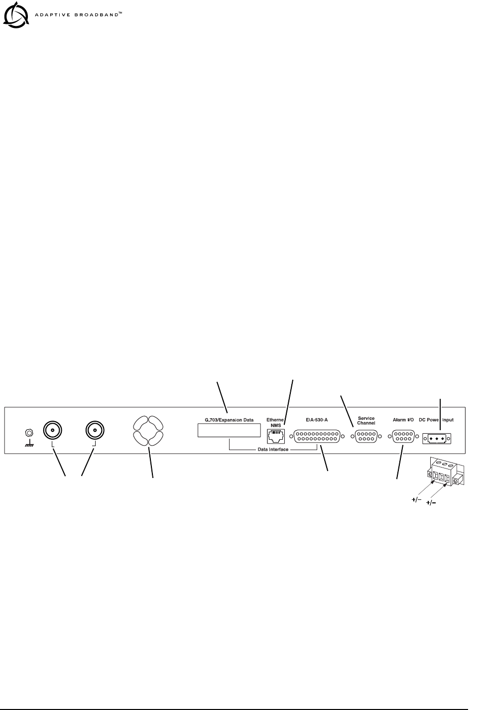
2.4 Radio Rear Panel Connectors
The rear panel of the standard LEDR “S” Series radio is shown in
Figure 8. Figure 9 shows the rear panel of a radio equipped with an FT1
Option Board. Refer to the descriptions that follow for specific informa-
tion regarding rear panel connections.
Invisible place holder
Figure 8. LEDR “S” Series Rear Panel (Standard)
Antenna/TX
External Duplexer
RX
Power Plug
Detail (see text)
GROUND STUD
COOLING FAN
EXPANSION DATA
DATA CONNECTOR
ETHERNET
SERVICE CHANNEL
ALARM INPUT & OUTPUT
DC POWER
RF CONNECTORS
Note: RX Connector present with external duplexer only.

MDS 05-3627A01, Rev. A LEDR “S” Series I/O Guide 11
Invisible place holder
Figure 9. LEDR “S” Series Rear Panel (With FT1 Option Board)
Ground Stud
The ground stud on the rear panel provides a point to tie the radio’s
chassis ground to earth ground for safety purposes.
Antenna/TX
The Antenna/TX connector is a coaxial N-type connector. When an
internal duplexer is installed, it serves as the connection point for the sta-
tion antenna. When an external duplexer is used, it acts as the transmitter
RF output connector to the duplexer.
RX
The RX (receive) connector is a coaxial N-type connector. It is only
installed if the radio is supplied for use with an external duplexer. It car-
ries receive signals from the duplexer to the transceiver.
When an external duplexer is used, ensure that the higher frequency
(transmit or receive) is connected to the duplexer connector marked
HI
and the lower frequency (transmit or receive) is connected to the
duplexer marked
LO
.
G.703 Data Connectors (4)
—For radios with FT1 Option Bd.
These RJ-45 jacks provide connection to G.703 customer-supplied data
interface equipment. Only one of the jacks is active (user selectable in
software). For pinout information, see Figure 26 on page 86.
Ethernet
The Ethernet connector provides access to the embedded SNMP agent
and other elements of the TCP/IP network-management interface. The
connector is a standard 10 base-T connection with an RJ-45 modular
connector.
Antenna/TX
External Duplexer
RX G.703/Expansion Data EIA-530-A
Ethernet
NMS
Data Interface
Service
Channel Alarm I/O DC Power Input
Power Plug
Detail (see text)
GROUND STUD
COOLING FAN
4 x G.703 DATA CONNECTORS
EIA-530 DATA CONNECTOR
ETHERNET
SERVICE CHANNEL
ALARM INPUT & OUTPUT
DC POWER
RF CONNECTORS
Note: RX Connector present with external duplexer only.
(Not Operational with FT1 board installed)
(Non-Protected version)

12 LEDR “S” Series I/O Guide MDS 05-3627A01, Rev. A
At a repeater site, the Ethernet connector must be connected to the other
radio with a cross-cable for the Orderwire and service channel to func-
tion properly.
For detailed pin information see, Figure 24 on page 85.
EIA-530-A
The EIA-530-A connector is the main data input/output connector for
the subrate radio. The EIA-530 interface is a high-speed serial data con-
nector. For detailed pin information, see “EIA-530-A Data” on page 85.
Service Channel
This is a 9-pin serial port with EIA-232-type signaling. For detailed pin
information, see “Service Channel” on page 86.
Alarm I/O
This is a 9-pin connector that has both inputs and outputs. The events
that cause alarm output signals can be configured in the radio software.
See “evmap” on page 43 for information on programing which events
trigger an alarm. See Figure 28 on page 86 for Alarm I/O pinout infor-
mation.
Power
Before connecting primary power to the radio, verify that it matches the
power supply operating range. Improper voltages may damage the
equipment. The allowable voltage limits are shown in Table 7. The
power connector is not polarity-sensitive.
The DC power connector is a three-pin keyed connector. The power
supply used can be connected with either polarity. The center conductor
is not connected.
Refer to the model number codes in Figure 3 to determine the radio’s
power supply range.
2.5 Protected Switch Rear Panel Connectors
The rear panel of the Protected Switch Chassis is shown in Figure 10.
Refer to the following descriptions for specific information regarding
rear panel connections.
Table 7. Power Supply Options
Nominal Input Voltage Allowable Voltage Range
24 Vdc 19.2 to 28.8 Vdc
48 Vdc 38.4 to 57.6 Vdc
CAUTION
POSSIBLE
EQUIPMENT
DAMAGE

MDS 05-3627A01, Rev. A LEDR “S” Series I/O Guide 13
Figure 11 presents an inter-unit cabling diagram for protected configu-
rations.
Invisible place holder
Figure 10. Protected Switch Chassis—Rear Panel
RxA
The RxA (receive, radio A) connector is a coaxial N-type connector. It
connects to the RX port on the rear panel of Radio A via a short coaxial
cable.
RxB
Same as RxA, but for Radio B.
Antenna
The Antenna connector is a coaxial N-type connector. It serves as the
connection point for the station antenna.
TxA
The TxA (transmit, radio A) connector is a coaxial N-type connector. It
connects to the TX port on the rear panel of Radio A via a short coaxial
cable.
TxB
Same as TxA, but for Radio B.
Protected Data
This pair of connectors accepts G.703 data signals from each of the
LEDR radios. The top connector is for Radio A, and the bottom con-
nector is for Radio B. For pinout information, see Figure 26 on page 86.
E1
These connectors are not operational on “S” Series (Subrate) radios.
TxBAntenna TxARxBRxA 530 (A&B) EIA-530-A Service ChannelEthernetE1Protected
12
34
B
A
ETHERNET
SERVICE CHANNEL
RF CONNECTORS E1 DATA
PROTECTED DATA 530 (A&B)
EIA-530-A

14 LEDR “S” Series I/O Guide MDS 05-3627A01, Rev. A
Ethernet
The Ethernet connector provides access to the embedded SNMP agent
and other elements of the TCP/IP network-management interface. The
connector is a standard 10 base-T connection with an RJ-45 modular
connector. For detailed pin information, Figure 24 on page 85.
530 (A&B)
This pair of DB-25 connectors accepts EIA-530 signals from each of the
LEDR radios. The top connector is for Radio A, and the bottom con-
nector is for Radio B. For pinout information, see Figure 26 on page 86.
EIA-530-A
This DB-25 connector provides a connection point for customer-sup-
plied EIA-530 data equipment.
Service Channel
In a protected configuration, this DB-9 connector becomes the Service
Channel connection for both LEDR radios. (The Service Channel con-
nectors on the radios become non-functional.) For detailed pin informa-
tion, see “Service Channel” on page 86.
2.6 Inter-Unit Cabling for Protected Stations
The required cabling between the two radios and the Protected Switch
chassis is shown in Figure 11.
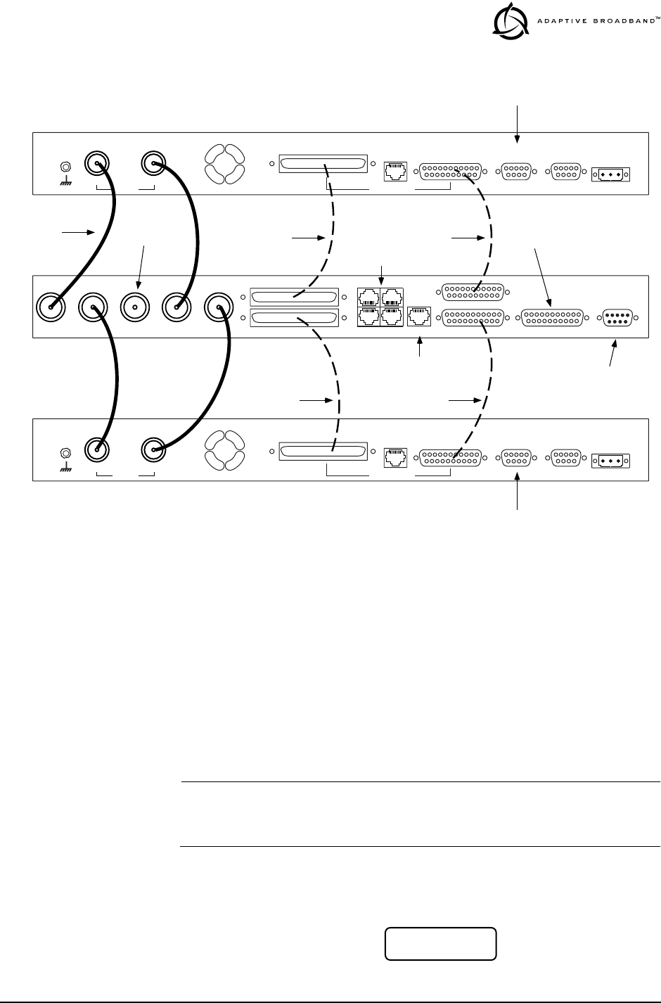
MDS 05-3627A01, Rev. A LEDR “S” Series I/O Guide 15
Invisible place holder
Figure 11. Inter-unit Cabling—Protected Version
3.0 OPERATION
The LEDR radio is designed for continuous, unattended operation.
Under normal conditions, the only time operator intervention is required
is to power the unit up or down, or to change an operating parameter.
This section explains the use of the radio’s controls and indicators and
provides steps for initial startup of the equipment.
3.1 Initial Startup
NOTE: The LEDR radio is normally keyed continuously, and the radio
will transmit whenever power is applied. Ensure there is a suit-
able load on the antenna connector before connecting power.
Operation of the radio can be started by simply connecting primary
power to the unit. After a short self-test, a “default screen” similar to the
following appears on the radio’s LCD display:
TxBAntenna TxARxBRxA 530 (A&B) EIA-530-A Service ChannelEthernetE1Protected
TX
External Data Interface
EIA-530-A
Ethernet
NMS
Service
Channel Alarm I/O DC Power Input
EIA-530-A
Ethernet
NMS
Data Interface
Service
Channel Alarm I/O DC Power Input
TO
STATION
ANTENNA
12
34
NOT USED WITH
FT1-EQUIPPED RADIOS
TO ETHERNET HUB
TO EIA-530
DATA EQUIPMENT
SERVICE CHANNEL
(SERVES BOTH RADIOS)
RX
COAXIAL CABLES (4)
P/N 19-1323A02 RIBBON CABLE
P/N 03-3828A01
SCSI CABLE
P/N 03-3837A01
TX
External
RX
G.703/Expansion Data
G.703/Expansion Data
NOT USED IN
PROTECTED CONFIG.
NOT USED IN
PROTECTED CONFIG.
RADIO A
RADIO B
PROTECTED SWITCH
RIBBON CABLE
P/N 03-3828A01
SCSI CABLE
P/N 03-3837A01
LL
LLEE
EEDD
DDRR
RR
LL
LLii
iinn
nnkk
kk
RR
RRSS
SSSS
SSII
II::
::
--
--66
6600
00
dd
ddBB
BBmm
mm

16 LEDR “S” Series I/O Guide MDS 05-3627A01, Rev. A
Maximizing RSSI
For newly installed systems, one of the first tasks is to orient the station
antenna for a maximum Received Signal Strength Indication (RSSI) as
shown on the LCD screen. See “Performance” on page 30 for details. A
maximum RSSI ensures the antenna is properly aimed at the associated
station. Move the antenna slowly while an assistant observes the RSSI
display for a maximum reading.
Initial Login—Required to change radio settings
When the radio is first powered up, it defaults to a read-only condition.
That is, the radio parameters may be viewed, but cannot be changed. To
enable changes to radio settings, a valid user name and password must
be entered.
When the radio is shipped from the factory, it is pre-programmed with
the following temporary login credentials:
Username: SUPER
Password: SUPER
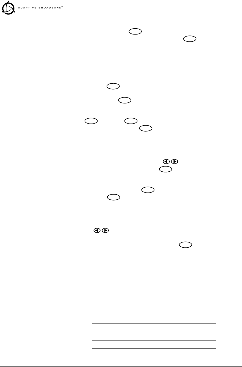
Keypad Method To log in from the front panel using the temporary credentials, follow
these steps:
1. Go to the Login screen and press the front panel key. The
Username screen appears with SUPER displayed.
2. Press the key again to access the Password screen. Use the
arrow keys to scroll through the list of characters and individually
select the letters spelling out the word SUPER. Press after each
character selection. (For more information on character selection
using the keypad, see “Communicating with the Radio” on page 18.)
3. When all of the characters have been entered, press again. The
screen briefly displays Login Success and returns to the Login entry
screen.
The user may now access any of the screens shown in Figure 14 with
Administrator level privileges (the highest allowable user level).
Console Method To login using a terminal connected to the front panel console port,
follow the steps below. (For more information on connecting a terminal,
see “Console Port” on page 35.)
1. Connect a terminal to the radio’s front panel console port and
press . The
ADAP> prompt will appear.
2. Enter login SUPER. The Password > prompt will appear.
ENTER
ENTER
ENTER
ENTER
ENTER

MDS 05-3627A01, Rev. A LEDR “S” Series I/O Guide 17
3. Enter the password SUPER. The following response appears: login:
SUPER logged in.
The user may now access any of the console commands listed in
Table 12 on page 36 with Administrator level privileges (the highest
allowable user level).
Changing the
SUPER Password
(Recommended)
The factory-programmed username and password (SUPER) is provided
to enable a System Administrator to operate a newly installed radio. It
is highly recommended that the password for SUPER be changed as soon
as possible to maintain system security.
Follow these steps to change the factory-programmed password:
1. Login as SUPER using the Console Method described above.
(Passwords cannot be changed using the front panel keypad.)
2. Enter the command passwd. At the next prompt, enter a new pass-
word (eight characters maximum).
3. Re-enter your new password (for verification purposes). If the entry
is correct, the radio responds with user: Command Complete.
You may now set up additional accounts, set permission levels, or delete
accounts as desired using the user command. See page 58 for complete
description of this command.
NOTE: It is recommended that users log out when finished using the
keypad or console terminal. This can be done using the Logout
screen on the radio, or the logout command from a console
terminal as appropriate. If there is no keypad or terminal
activity for 10 minutes, the radio automatically logs out and
reverts to read-only status.
18 LEDR “S” Series I/O Guide MDS 05-3627A01, Rev. A
3.2 Communicating with the Radio
There are four different methods available to set radio parameters and
query the radio.
•Front Panel—The front panel is intended to serve as a conve-
nient user interface for local radio management. Most, but not
all, parameters and functions are accessible from the front
panel.
•SNMP Network Management System—The SNMP agent
interface is optimized to fulfill the fault configuration, perfor-
mance and user access requirements of the LEDR radio system.
A separate guide, P/N 05-3532A01 explains SNMP in more
detail.
• Telnet—A standard network application protocol which pro-
vides a console-type interface to configure and query most radio
parameters.
• EMS (Element Management System)—The EMS is used via
a terminal connected to the front panel console port. It may be
used to configure and query every manageable radio parameter
on a given network using the out-of-band service channel. The
EMS may be used on the local radio (login command) or on the
remote radio (rlogin command).
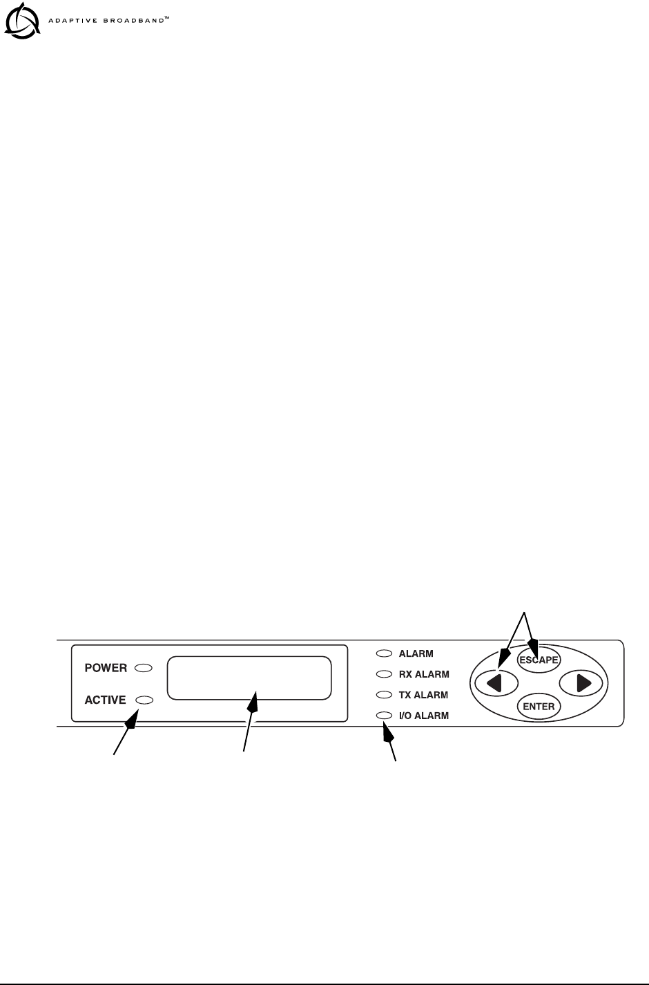
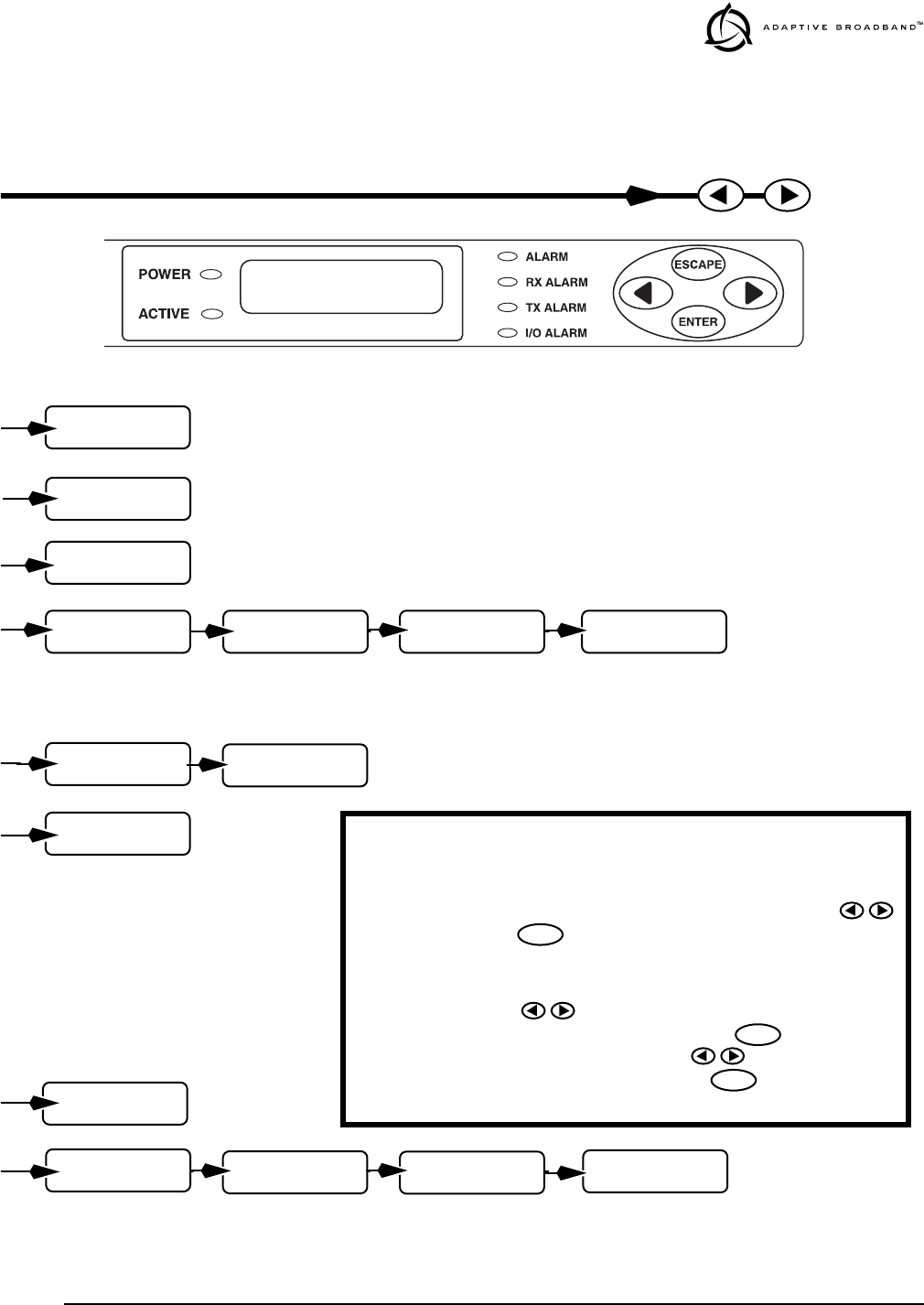
Front Panel Controls
Figure 12 shows the LEDR radio’s front panel controls and indicators.
The front panel includes LEDs, an LCD display screen and a menu nav-
igation keypad.
Figure 12. Front Panel Interface
MENU NAVIGATION BUTTONS
ALARM STATUS LEDS
STATUS LEDS LCD DISPLAY
MDS 05-3627A01, Rev. A LEDR “S” Series I/O Guide 19
LEDs The front panel LEDs indicate the following conditions when lit:
POWER—Main Power is applied to radio.
ACTIVE—This is the Primary unit in a redundant configuration.
ALARM—A general alarm condition is present
RX ALARM—The modem is not locked to a receive signal
TX ALARM—There is a problem with the transmitter
I/O ALARM—There is a payload data interface error
LCD Display/Keypad The LCD display provides a 2 line by 16 character readout of radio
status and parameter settings. It is used with the menu navigation
keypad on the right side of the front panel to control the radio’s opera-
tion and access diagnostic information.
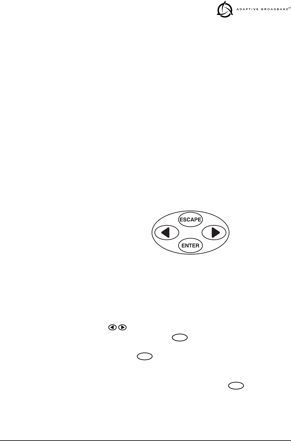
Use of the keypad (Figure 13) is simple, and allows many basic oper-
ating tasks to be performed without connecting an external terminal or
using additional software.
Invisible place holder
Figure 13. Menu Navigation Keypad
The keypad buttons can be used for two functions; Navigation, and
Editing. The functions of the keys are automatically selected according
to the screen that is being viewed by the user.
•Navigation Mode—This is the default mode. The left and right
keys ( ) navigate through the available top level screens (see
menu tree, Figure 14). The key allows entry into a screen,
exposing another level of menus or entering edit mode for a radio
parameter. The key always exits the current screen, causing
the program to “pop out” one level.
•Edit Mode—In editable screens, pressing the key puts the
screen in Edit mode. The technique for applying new data depends
on the particular edit mode used by that screen. LEDR screens have
four edit sub-modes; List, Character edit, Text Entry, and Horizon-
tal Bar.
ENTER
ENTER
ENTER
20 LEDR “S” Series I/O Guide MDS 05-3627A01, Rev. A
In List mode, the left and right keys scroll through a list of
choices. Pressing when the desired choice is selected
attempts to apply the changes. Pressing drops out of the
edit mode without saving changes.
The Character Edit mode consists a cursor move mode and a
character scroll mode. Upon entering the Character Edit mode,
the left and right keys move the cursor in the corresponding
direction. When the cursor is below the character to change,
pressing again puts the screen in character scroll mode in
which the left and right keys scroll through the available charac-
ters. Pressing saves the new character and reverts to cursor
move mode. To save all changes made in cursor move mode,
place the cursor under the special “Enter” character and press
. Pressing in character scroll mode reverts to cursor
move mode. Pressing in cursor move mode cancels char-
acter edit mode without saving any changes.
The Text Entry mode is a slight modification to the Character
Edit mode above. Upon entering Text Entry mode the cursor is
in the leftmost position and the keys scroll through the
available characters. Pressing saves the current character
and moves the cursor to the next position to the right. When the
text is correctly entered, moving the cursor to the special “Enter”
character and pressing attempts to save the new text.
Pressing in cursor move mode cancels Text Entry mode
without saving any changes.
The Horizontal Bar mode is used in some menu screens. It
allows adjustment of the LCD display for the best contrast using
the keys (see Front Panel menu, page 33). The right key
corresponds to upward viewing angle; the left key corresponds
to downward viewing angle. Pressing saves the adjusted
value as the default setting.
It works in a similar manner for the Orderwire menu (see page
33) to adjust the Volume and VOX threshold.
Front Panel Menu Tree
The LEDR radio contains several top level menus (see Table 8). These
serve as entry points to a variety of sub menus that can be used to view
or adjust operating parameters and diagnose the radio link.
ENTER
ENTER
ENTER
ENTER
ENTER
ENTER
ENTER
ENTER
ENTER
ENTER
ENTER
Table 8. Top Level Menu Screens
1) Login/Logout 9) Modem
2) Network 10) Console
3) General 11) Diagnostics
4) RF Configuration 12) Orderwire

MDS 05-3627A01, Rev. A LEDR “S” Series I/O Guide 21
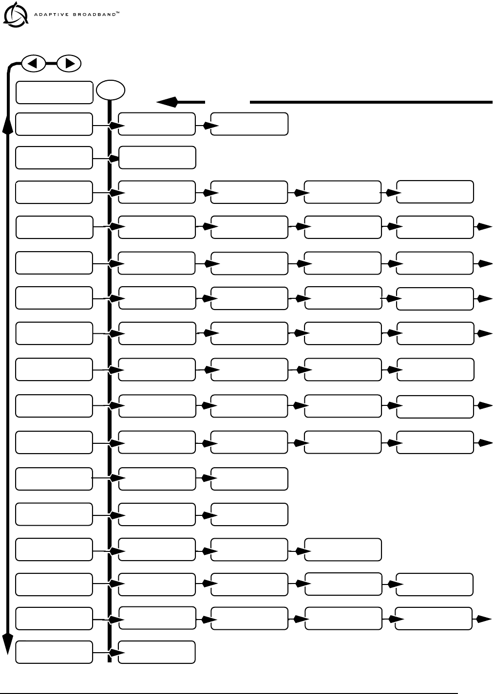
Figure 14 on the following page shows a pictorial view of the front panel
menu tree. Detailed explanations of the screens are given in Section 3.3,
Front Panel LCD Menu Descriptions (beginning on page 24).
5) IO Configuration 13) Front Panel
6) Line Configuration 14) Redundant
7) Performance 15) Remote Status
8) G.821
Table 8. Top Level Menu Screens (Continued)
22 LEDR “S” Series I/O Guide MDS 05-3627A01, Rev. A
Invisible place holder
Figure 14. Front Panel LCD Menu Navigation
UU
UUss
ssee
eerr
rrnn
nnaa
aamm
mmee
ee
AA
AAdd
ddmm
mmii
iinn
nn
PP
PPaa
aass
ssss
ssww
wwoo
oorr
rrdd
dd
**
****
****
****
****
****
**
II
IIPP
PP
AA
AAdd
dddd
ddrr
rree
eess
ssss
ss
00
0000
0000
00..
..00
0000
0000
00..
..00
0000
0000
00..
..00
0000
0000
00
GG
GGaa
aatt
ttee
eeww
wwaa
aayy
yy
00
0000
0000
00..
..00
0000
0000
00..
..00
0000
0000
00..
..00
0000
0000
00
NN
NNee
eett
ttmm
mmaa
aass
sskk
kk
00
0000
0000
00..
..00
0000
0000
00..
..00
0000
0000
00..
..00
0000
0000
00
FF
FFii
iirr
rrmm
mmww
wwaa
aarr
rree
ee
RR
RRee
eevv
vv..
..
xx
xx..
..xx
xx..
..xx
xx
SS
SSee
eerr
rrii
iiaa
aall
ll
NN
NNuu
uumm
mmbb
bbee
eerr
rr
xx
xxxx
xxxx
xxxx
xxxx
xxxx
xxxx
xxxx
xxxx
xxxx
xxxx
xxxx
xx
MM
MMoo
oodd
ddee
eell
ll
NN
NNuu
uumm
mmbb
bbee
eerr
rr
LL
LLEE
EEDD
DDRR
RR
44
4400
0000
00SS
SS
UU
UUnn
nnii
iitt
tt
II
IIDD
DD
00
0000
0000
00
BB
BBaa
aann
nndd
ddww
wwii
iidd
ddtt
tthh
hh
22
2200
0000
00
kk
kkHH
HHzz
zz
TT
TTxx
xx
FF
FFrr
rree
eeqq
qquu
uuee
eenn
nncc
ccyy
yy
xx
xxxx
xxxx
xxxx
xx..
..xx
xxxx
xxxx
xxxx
xx
MM
MMHH
HHzz
zz
PP
PPAA
AA
TT
TTee
eemm
mmpp
ppee
eerr
rraa
aatt
ttuu
uurr
rree
ee
++
++33
3377
77
°°
°°CC
CC
PP
PPoo
ooww
wwee
eerr
rr
OO
OOuu
uutt
tt
++
++33
3300
00
dd
ddBB
BBmm
mm
SS
SSNN
NNRR
RR
++
++22
2277
77
dd
ddBB
BB
RR
RRSS
SSSS
SSII
II
--
--66
6600
00
dd
ddBB
BBmm
mm
AA
AAvv
vvaa
aaii
iill
llaa
aabb
bbll
llee
ee
00
00
EE
EErr
rrrr
rroo
oorr
rree
eedd
dd
00
00
ss
ssee
eecc
cc
UU
UUnn
nncc
ccoo
oorr
rrrr
rree
eecc
cctt
ttaa
aabb
bbll
llee
ee
00
00
bb
bbll
lloo
oocc
cckk
kkss
ss
CC
CCoo
oorr
rrrr
rree
eecc
cctt
ttee
eedd
dd
00
00
bb
bbyy
yytt
ttee
eess
ss
BB
BBaa
aauu
uudd
dd
RR
RRaa
aatt
ttee
ee
99
9966
6600
0000
00
PP
PPaa
aarr
rrii
iitt
ttyy
yy
NN
NNoo
oonn
nnee
ee
RR
RRxx
xx
LL
LLoo
oocc
cckk
kk
LL
LLOO
OOCC
CCKK
KKEE
EEDD
DD
LL
LLoo
oooo
oopp
ppbb
bbaa
aacc
cckk
kk
NN
NNOO
OORR
RRMM
MMAA
AALL
LL
((
((NN
NNOO
OONN
NNEE
EE))
))
BB
BBuu
uuii
iill
lltt
tt
ii
iinn
nn
TT
TTee
eess
sstt
tt
SS
SStt
ttaa
aarr
rrtt
tt??
??
SS
SSee
eenn
nndd
dd
OO
OODD
DDWW
WW
AA
AAll
llee
eerr
rrtt
tt
44
4400
0000
00
BB
BBaa
aacc
cckk
kkll
llii
iigg
gghh
hhtt
tt
EE
EENN
NNAA
AABB
BBLL
LLEE
EEDD
DD
VV
VVii
iiee
eeww
wwii
iinn
nngg
gg
AA
AAnn
nngg
ggll
llee
ee
~~
~~~~
~~~~
~~~~
~~
KK
KKee
eeyy
yypp
ppaa
aadd
dd
BB
BBee
eeee
eepp
pp
EE
EENN
NNAA
AABB
BBLL
LLEE
EEDD
DD
KK
KKee
eeyy
yy
RR
RRee
eepp
ppee
eeaa
aatt
tt
RR
RRaa
aatt
ttee
ee
11
1155
5500
00
mm
mmss
ss
Details Page 24
Details Page 24
Details Page 24
Details Page 25
Details Page 30
Details Page 31
Details Page 32
Details Page 32
Details Page 33
Details Page 33
Details Page 33
LL
LLEE
EEDD
DDRR
RR
LL
LLii
iinn
nnkk
kk
DD
DDee
eeff
ffaa
aauu
uull
lltt
tt
SS
SScc
ccrr
rree
eeee
eenn
nn
LL
LLEE
EEDD
DDRR
RR
LL
LLii
iinn
nnkk
kk
LL
LLoo
oogg
ggii
iinn
nn
LL
LLEE
EEDD
DDRR
RR
LL
LLii
iinn
nnkk
kk
NN
NNee
eett
ttww
wwoo
oorr
rrkk
kk
LL
LLEE
EEDD
DDRR
RR
LL
LLii
iinn
nnkk
kk
GG
GGee
eenn
nnee
eerr
rraa
aall
ll
LL
LLEE
EEDD
DDRR
RR
LL
LLii
iinn
nnkk
kk
RR
RRFF
FF
CC
CCoo
oonn
nnff
ffii
iigg
gg
LL
LLEE
EEDD
DDRR
RR
LL
LLii
iinn
nnkk
kk
PP
PPee
eerr
rrff
ffoo
oorr
rrmm
mmaa
aann
nncc
ccee
ee
LL
LLEE
EEDD
DDRR
RR
LL
LLii
iinn
nnkk
kk
GG
GG..
..88
8822
2211
11
LL
LLEE
EEDD
DDRR
RR
LL
LLii
iinn
nnkk
kk
CC
CCoo
oonn
nnss
ssoo
ooll
llee
ee
LL
LLEE
EEDD
DDRR
RR
LL
LLii
iinn
nnkk
kk
MM
MMoo
oodd
ddee
eemm
mm
LL
LLEE
EEDD
DDRR
RR
LL
LLii
iinn
nnkk
kk
DD
DDii
iiaa
aagg
ggnn
nnoo
ooss
sstt
ttii
iicc
ccss
ss
LL
LLEE
EEDD
DDRR
RR
LL
LLii
iinn
nnkk
kk
OO
OOrr
rrdd
ddee
eerr
rrww
wwii
iirr
rree
ee
LL
LLEE
EEDD
DDRR
RR
LL
LLii
iinn
nnkk
kk
FF
FFrr
rroo
oonn
nntt
tt
PP
PPaa
aann
nnee
eell
ll
ENTER Step 2
Step 3
Display Only
Display Only
Display Only Display Only
Display Only
Display Only
Display Only
Menu Selections Menu Selections
Menu Selections
Number Enter Number Enter Number Enter
Text Enter
Menu Selection
Number Enter Number Enter
Display Only
Display OnlySet/Display
Number Enter
Display Only
Display Only
Display Only
Menu Selection
Menu Selection Menu Selection
Menu Selection
Menu Selection
Menu Selection
Menu Selection
Step 1
RR
RRxx
xx
FF
FFrr
rree
eeqq
qquu
uuee
eenn
nncc
ccyy
yy
xx
xxxx
xxxx
xxxx
xx..
..xx
xxxx
xxxx
xxxx
xx
MM
MMHH
HHzz
zz
TT
TTxx
xxKK
KKee
eeyy
yy
EE
EEnn
nnaa
aabb
bbll
llee
ee
UU
UUNN
NN--
--KK
KKEE
EEYY
YYEE
EEDD
DD
Display Only Display Only
VV
VVoo
ooll
lluu
uumm
mmee
ee
~~
~~~~
~~~~
~~~~
~~~~
~~~~
~~
VV
VVoo
ooxx
xx
TT
TThh
hhrr
rree
eess
sshh
hhoo
ooll
lldd
dd
~~
~~~~
~~~~
~~~~
~~~~
~~~~
~~
Level Setting Level Setting
Angle Setting
GG
GG..
..88
8822
2211
11
SS
SStt
ttaa
aatt
ttuu
uuss
ss
EE
EERR
RRRR
RROO
OORR
RR
FF
FFRR
RREE
EEEE
EE
UU
UUnn
nnaa
aavv
vvaa
aaii
iill
llaa
aabb
bbll
llee
ee
00
00
ss
ssee
eecc
cc
FF
FFrr
rree
eeqq
qq..
..
OO
OOff
ffff
ffss
ssee
eett
tt
--
--11
1177
7700
00
HH
HHzz
zz
DD
DDee
eeff
ffaa
aauu
uull
lltt
tt
II
IIPP
PP
PP
PPoo
oorr
rrtt
tt
00
0000
0000
00..
..00
0000
0000
00..
..00
0000
0000
00..
..00
0000
0000
00
Number Enter
Details Page 24
LL
LLEE
EEDD
DDRR
RR
LL
LLii
iinn
nnkk
kk
LL
LLoo
oogg
ggoo
oouu
uutt
tt
Number Enter
Display Only
(Note: Logout screens available only when logged in.)
SS
SSii
iibb
bbll
llii
iinn
nngg
gg
SS
SStt
ttaa
aatt
ttuu
uuss
ss
OO
OOKK
KK
AA
AAcc
cctt
ttii
iivv
vvee
ee
NN
NNOO
OO
Details Page 34
LL
LLEE
EEDD
DDRR
RR
LL
LLii
iinn
nnkk
kk
RR
RRee
eedd
dduu
uunn
nndd
ddaa
aann
nntt
tt
Display Only Display Only
Display Only
RR
RRee
eemm
mmoo
oott
ttee
ee
UU
UUnn
nnii
iitt
ttII
IIDD
DD
<<
<<nn
nnoo
oonn
nnee
ee>>
>> Numeric Entry
Details Page 27
LL
LLEE
EEDD
DDRR
RR
LL
LLii
iinn
nnkk
kk
II
IIOO
OO
CC
CCoo
oonn
nnff
ffii
iigg
gg
Details Page 28
LL
LLEE
EEDD
DDRR
RR
LL
LLii
iinn
nnkk
kk
LL
LLii
iinn
nnee
ee
CC
CCoo
oonn
nnff
ffii
iigg
gg
Details Page 35
LL
LLEE
EEDD
DDRR
RR
LL
LLii
iinn
nnkk
kk
RR
RRee
eemm
mmoo
oott
ttee
ee
SS
SStt
ttaa
aatt
ttuu
uuss
ss
Details Page 26
CC
CCll
lloo
oocc
cckk
kk
MM
MMoo
oodd
ddee
ee
II
IINN
NNTT
TTEE
EERR
RRNN
NNAA
AALL
LL
Menu Selection (see note)
II
IInn
nntt
ttee
eerr
rrff
ffaa
aacc
ccee
ee
EE
EE11
11
Menu Selection
FF
FFDD
DDLL
LL
EE
EEnn
nnaa
aabb
bbll
llee
ee
DD
DDII
IISS
SSAA
AABB
BBLL
LLEE
EEDD
DD
Menu Selection
CC
CCAA
AASS
SS
EE
EEnn
nnaa
aabb
bbll
llee
ee
DD
DDII
IISS
SSAA
AABB
BBLL
LLEE
EEDD
DD
Menu Selection
CC
CChh
hhoo
oooo
ooss
ssee
ee
LL
LLii
iinn
nnee
ee
11
11
LL
LLII
IINN
NNEE
EE11
11
Menu Selection
FF
FFrr
rraa
aamm
mmee
ee
SS
SStt
ttrr
rruu
uucc
cctt
tt
11
11
FF
FFAA
AASS
SS
OO
OONN
NNLL
LLYY
YY
Menu Selection
AA
AAII
IISS
SS
GG
GGee
eenn
nnee
eerr
rraa
aatt
ttee
ee
11
11
OO
OOFF
FFFF
FF
AA
AAII
IISS
SS
FF
FFoo
oorr
rrww
wwaa
aarr
rrdd
ddii
iinn
nngg
gg
11
11
OO
OOFF
FFFF
FF
Menu SelectionMenu Selection
Note: This menu tree shows the selections available on radios equipped with an FT1 Option Board.
Standard “S” Series radios will have fewer selections.
MM
MMoo
oodd
ddee
ee
11
11
++
++
11
11
HH
HHOO
OOTT
TT
MM
MMyy
yy
SS
SStt
ttaa
aatt
ttuu
uuss
ss
OO
OOKK
KK
Menu Selection
LL
LLEE
EEDD
DDRR
RR
LL
LLii
iinn
nnkk
kk
LL
LLoo
oogg
gggg
ggee
eedd
dd
oo
oouu
uutt
tt
MDS 05-3627A01, Rev. A LEDR “S” Series I/O Guide 23
Invisible place holder
HH
HHaa
aarr
rrdd
ddww
wwaa
aarr
rree
ee
RR
RRee
eevv
vv..
..
xx
xxxx
xxxx
xxxx
xxxx
xxxx
xxxx
xxxx
xx
SS
SSee
eevv
vvee
eerr
rree
eell
llyy
yy
EE
EErr
rrrr
rree
eedd
dd
00
00
ss
ssee
eecc
cc
DD
DDee
eeff
ffaa
aauu
uull
lltt
tt
SS
SScc
ccrr
rree
eeee
eenn
nn
RR
RRSS
SSSS
SSII
II
Display Only
Menu Selection
Display Only
Display Only
Display Only—This description indicates the LCD menu item is for
informational purposes only.
Menu Selection—This description indicates there are selections
available and the choices may be scrolled through using the
buttons. Press the button again to save menu selection
choice.
Text or Number Enter— This description indicates the entry is
alphanumeric. The buttons are first used to position the
cursor over the text to be changed. Then, the button is
pressed to enter the edit mode. Use the buttons to scroll
through all available characters. Press the button again to
save the displayed character in displayed location.
ENTER
ENTER
ENTER
RR
RREE
EESS
SSEE
EETT
TT
GG
GG..
..88
8822
2211
11??
??
NN
NNOO
OO
Menu Selection
MM
MMoo
oodd
dd//
//DD
DDaa
aatt
ttaa
aa
rr
rraa
aatt
ttee
ee
33
3322
22--
--QQ
QQAA
AAMM
MM
77
7766
6688
88
kk
kkbb
bbpp
ppss
ss
BB
BBii
iitt
tt
EE
EErr
rrrr
rroo
oorr
rr
RR
RRaa
aatt
ttee
ee
<<
<<
11
11
xx
xx
11
1100
00--
--66
66
LL
LLii
iinn
nnee
ee
mm
mmaa
aapp
pp
11
11aa
aa
22
22bb
bb
33
33cc
cc
44
44dd
dd
Menu Selection
LL
LLii
iinn
nnee
ee
CC
CCoo
oodd
ddee
ee
11
11
AA
AAMM
MMII
II
Menu Selection
RR
RRee
eeff
ffrr
rraa
aamm
mmee
ee
11
11
33
33
cc
ccoo
oonn
nnss
ss..
..
FF
FFAA
AASS
SS
Menu Selection
PP
PPuu
uull
llss
ssee
ee
SS
SShh
hhaa
aapp
ppee
ee
11
11
gg
gg..
..77
7777
7755
55
Menu Selection
CC
CCaa
aabb
bbll
llee
ee
LL
LLee
eenn
nngg
ggtt
tthh
hh
11
11
11
11--
--11
1133
3333
33
ff
fftt
tt
Menu Selection
(Note: Redundant screens visible
only on protected/redundant
stations)
HH
HHii
iitt
ttll
llee
eess
ssss
ss
OO
OONN
NN
DD
DDee
eeff
ffaa
aauu
uull
lltt
tt
RR
RRaa
aadd
ddii
iioo
oo
YY
YYee
eess
ss
SS
SSii
iibb
bbll
llii
iinn
nngg
gg
II
IIPP
PP
00
0000
0000
00..
..00
0000
0000
00..
..00
0000
0000
00..
..00
0000
0000
00
SS
SSww
wwii
iitt
ttcc
cchh
hh
XX
XXcc
ccvv
vvrr
rr
SS
SSww
wwii
iitt
ttcc
cchh
hh??
??
Numeric Entry Menu Selection Menu Selection Menu Selection
(Note: Redundant screens
visible only on protected/
redundant stations)
(Note: Earlier versions of the software may display the Clock Mode as
NORMAL
instead of
INTERNAL
.)
24 LEDR “S” Series I/O Guide MDS 05-3627A01, Rev. A
3.3 Front Panel LCD Menu Descriptions
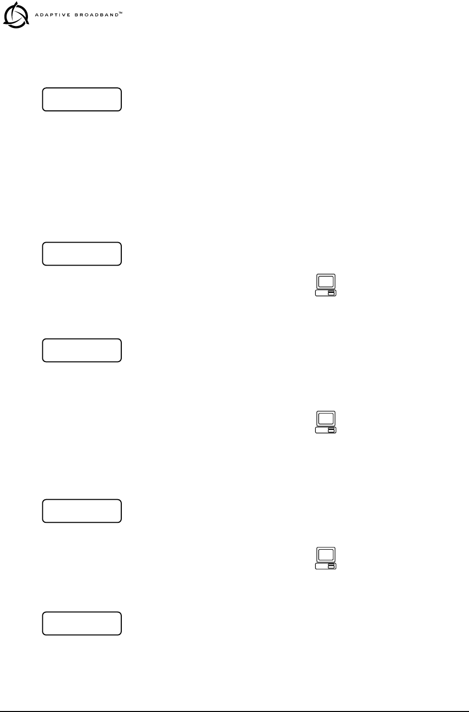
Default Parameters
This menu allows you to view the default screen that appears on the
LCD display. If desired, the default screen may be changed (see
“
Default Screen
” on page 34).
Login
The login menus allow you to log in to the radio’s operating system and
gain access to configuration and diagnostics functions permitted for
your assigned access level.
The username menu is where you specify the user name assigned by the
user access administrator.
The password screen is where you specify the password associated with
your user name to gain access to the login account. A maximum of eight
characters are allowed.
Network
This menu allows changes to the radio’s IP address. The IP address is
used for SNMP connectivity. The IP address also allows new radio soft-
ware to be downloaded over-the-air.
This menu allows the subnet mask to be viewed and changed. The
subnet mask specifies which bits of the host IP address can be re-used
for increased network addressing efficiency.
Example: Consider an IP address in a Class C network, such as
150.215.017.009. The Class C network means that the right-most group
of numbers (009) identifies a particular host on this network. The other
three groups of numbers (150.215.017) represent the network address.
LL
LLEE
EEDD
DDRR
RR
LL
LLii
iinn
nnkk
kk
DD
DDee
eeff
ffaa
aauu
uull
lltt
tt
SS
SScc
ccrr
rree
eeee
eenn
nn
UU
UUss
ssee
eerr
rrnn
nnaa
aamm
mmee
ee
AA
AAdd
ddmm
mmii
iinn
nn
For the console
command-line equivalent,
see “login” on page 48
PP
PPaa
aass
ssss
ssww
wwoo
oorr
rrdd
dd
**
****
****
****
****
****
**
For the console
command-line equivalent,
see “passwd” on page 51
II
IIPP
PP
AA
AAdd
dddd
ddrr
rree
eess
ssss
ss
00
0000
0000
00..
..00
0000
0000
00..
..00
0000
0000
00..
..00
0000
0000
00
For the console
command-line equivalent,
see “ip” on page 46
NN
NNee
eett
ttmm
mmaa
aass
sskk
kk
00
0000
0000
00..
..00
0000
0000
00..
..00
0000
0000
00..
..00
0000
0000
00

MDS 05-3627A01, Rev. A LEDR “S” Series I/O Guide 25
Subnetting allows the further division of the host part of the address
(right-most group of numbers) into two or more subnets. A subnet mask
of 255.255.255.127 allows half of the host portion of the IP address to
be reused to define sub-networks.
This menu allows the Gateway IP address to be viewed or set. The
Gateway IP address is the address of the radio that connects the radio
network to an IP network.
This menu allows selection of the Default IP port for networking con-
nections to the LEDR radio. The
Ethernet
selection is used for cable con-
nection to a Local Area Network (LAN) or repeater via the radio’s rear
panel
ETHERNET NMS
connector.
The
AIR
selection is commonly used for over-the air (RF) networking
between radios, but may also be used with a back-to-back cable connec-
tion between two radios via the radio’s rear panel
ETHERNET NMS
con-
nector. This type of communication uses the SNAP protocol and
requires the use of an ethernet crossover cable.
General
This menu allows the Unit ID of the radio to be displayed or changed.
The Unit ID allows an individual radio to be signaled for Orderwire use.
This menu displays the radio model number. The radio type cannot be
changed by the user.
For the console
command-line equivalent,
see “ip” on page 46
GG
GGaa
aatt
ttee
eeww
wwaa
aayy
yy
00
0000
0000
00..
..00
0000
0000
00..
..00
0000
0000
00..
..00
0000
0000
00
For the console
command-line equivalent,
see “ip” on page 46
DD
DDee
eeff
ffaa
aauu
uull
lltt
tt
II
IIPP
PP
PP
PPoo
oorr
rrtt
tt
EE
EEtt
tthh
hhee
eerr
rrnn
nnee
eett
tt
For the console
command-line equivalent,
see “ip” on page 46
UU
UUnn
nnii
iitt
tt
II
IIDD
DD
00
0000
0000
00
For the console
command-line equivalent,
see “unitid” on page 58
MM
MMoo
oodd
ddee
eell
ll
NN
NNuu
uumm
mmbb
bbee
eerr
rr
LL
LLEE
EEDD
DDRR
RR
11
1144
4400
0000
00SS
SS For the console
command-line equivalent,
see “model” on page 51
26 LEDR “S” Series I/O Guide MDS 05-3627A01, Rev. A
This menu displays the radio serial number and matches the serial
number on the chassis sticker. The radio serial number cannot be
changed by the user.
This menu displays the firmware revision level of the internal radio soft-
ware.
This menu displays the hardware revision level of the main PC board in
the radio.
RF Configuration
This menu is used to set or view the transmit (TX) frequency of the
radio.
This menu is used to set or view the receive (RX) frequency of the radio.
This menu is used to enable (key) or disable (dekey) the transmitter or
to verify that the radio is keyed and the transmitter is active. The radio
is normally keyed and transmitting whenever power is applied.
This menu displays the bandwidth setting of the radio. The bandwidth is
set at the factory and cannot be changed by the user. Refer to Table 17
on page 61 for allowable combinations of bandwidth, data rates, and
modulation types.
SS
SSee
eerr
rrii
iiaa
aall
ll
NN
NNuu
uumm
mmbb
bbee
eerr
rr
xx
xxxx
xxxx
xxxx
xxxx
xxxx
xxxx
xxxx
xxxx
xxxx
xxxx
xxxx
xx
For the console
command-line equivalent,
see “sernum” on page 55
FF
FFii
iirr
rrmm
mmww
wwaa
aarr
rree
ee
RR
RRee
eevv
vv..
..
xx
xxxx
xxxx
xxxx
xxxx
xxxx
xxxx
xxxx
xx For the console
command-line equivalent,
see “ver” on page 59
HH
HHaa
aarr
rrdd
ddww
wwaa
aarr
rree
ee
RR
RRee
eevv
vv..
..
xx
xxxx
xxxx
xxxx
xxxx
xxxx
xxxx
xxxx
xx For the console
command-line equivalent,
see “ver” on page 59
TT
TTxx
xx
FF
FFrr
rree
eeqq
qquu
uuee
eenn
nncc
ccyy
yy
For the console
command-line equivalent,
see “freq” on page 44
RR
RRxx
xx
FF
FFrr
rree
eeqq
qquu
uuee
eenn
nncc
ccyy
yy
For the console
command-line equivalent,
see “freq” on page 44
TT
TTxx
xx
KK
KKee
eeyy
yy
EE
EEnn
nnaa
aabb
bbll
llee
ee
For the console
command-line equivalent,
see “txkey” on page 58
BB
BBaa
aann
nndd
ddww
wwii
iidd
ddtt
tthh
hh

MDS 05-3627A01, Rev. A LEDR “S” Series I/O Guide 27
This menu displays the modulation type and the aggregate link data rate.
The available modulation types are 16 QAM, 32 QAM, and 64 QAM.
The data rate can be changed, but is dependent on the modulation type.
See “Bandwidths, Data Rates and Modulation Types” on page 61.
IO Configuration
This screen is used to set or display the data clocking method. For syn-
chronization purposes, several different clocking schemes can be used.
See “Transmit Clock Selection” on page 62.
NOTE:
Earlier versions of the software may display the Clock Mode
as
NORMAL
instead of
INTERNAL
.
This screen is used to set or display the payload data interface. The
available selections are E1 and T1, depending on hardware configura-
tion of the LEDR radio.
This screen is used to set or display the Facility Data Link (FDL) status
for T1 operation. Valid selections are Enabled and Disabled.
This screen is used to set or displays the Channel Associated Signaling
(CAS) status. The available selections are Enabled and Disabled.
This screen is used to set or display the current span mapping configu-
ration. The entry consists of from 1 to 4 alpha-numeric characters spec-
ifying line interface to span mapping. Valid numbers are 1–4. Valid span
characters are a–d.
MM
MMoo
oodd
dd//
//DD
DDaa
aatt
ttaa
aa
rr
rraa
aatt
ttee
ee
33
3322
22--
--QQ
QQAA
AAMM
MM
77
7766
6688
88
kk
kkbb
bbpp
ppss
ss
For the console
command-line equivalent,
see “modem” on page 51
CC
CCll
lloo
oocc
cckk
kk
MM
MMoo
oodd
ddee
ee
II
IINN
NNTT
TTEE
EERR
RRNN
NNAA
AALL
LL
For the console
command-line equivalent,
see “clkmode” on page 42
II
IInn
nntt
ttee
eerr
rrff
ffaa
aacc
ccee
ee
EE
EE11
11
For the console
command-line equivalent,
see “interface” on page 46
FF
FFDD
DDLL
LL
EE
EEnn
nnaa
aabb
bbll
llee
ee
DD
DDII
IISS
SSAA
AABB
BBLL
LLEE
EEDD
DD
For the console
command-line equivalent,
see “modem” on page 51
CC
CCAA
AASS
SS
EE
EEnn
nnaa
aabb
bbll
llee
ee
DD
DDII
IISS
SSAA
AABB
BBLL
LLEE
EEDD
DD
For the console
command-line equivalent,
see “modem” on page 51
LL
LLii
iinn
nnee
ee
mm
mmaa
aapp
pp
11
11aa
aa
22
22bb
bb
33
33cc
cc
44
44dd
dd

28 LEDR “S” Series I/O Guide MDS 05-3627A01, Rev. A
Example: Entering 1a 2b 3c 4d causes the following:
maps line 1 to span a
maps line 2 to span b
maps line 3 to span c
maps line 4 to span d
Line Configuration
This screen is used to choose or display the line (1-4) that is selected.
This selection will be active for all of the screens that follow in the Line
Configuration menu and will be displayed in the upper right hand corner
of each screen.
This screen is used to set or display the span(s) frame structure. The
allowable selections are shown in Table 9.
This screen is used to set or display the Alarm Indication Signal (AIS)
status. It may be set to ON or OFF. When generation is enabled, fault
conditions within the link or at the line interface will cause the appro-
priate AIS signaling to occur.
For the console
command-line equivalent,
see “linemap” on page 47
CC
CChh
hhoo
oooo
ooss
ssee
ee
LL
LLii
iinn
nnee
ee
11
11
LL
LLII
IINN
NNEE
EE11
11
For the console
command-line equivalent,
see “linename” on page 48
FF
FFrr
rraa
aamm
mmee
ee
SS
SStt
ttrr
rruu
uucc
cctt
tt
11
11
FF
FFAA
AASS
SS
OO
OONN
NNLL
LLYY
YY
Table 9. Frame Structure—Allowable Selections
T1 Operation E1 Operation
0–FT only (Default) 0–FAS Only (Default)
1–ESF 1–FAS + BSLIP
2–ESF + PRM 2–FAS + CRC
3–SF 3–FAS + CRC + BSLIP
4–SF + JYEL 4–FAS + CAS
5–ESF + CRC 5–FAS + CAS + BSLIP
6–ESF + CRC + PRM 6–FAS + CRC + CAS
7–FAS +CRC + CAS +BSLIP
For the console
command-line equivalent,
see “fstruct” on page 44
AA
AAII
IISS
SS
GG
GGee
eenn
nnee
eerr
rraa
aatt
ttee
ee
11
11
OO
OOFF
FFFF
FF
For the console
command-line equivalent,
see “ais” on page 40

MDS 05-3627A01, Rev. A LEDR “S” Series I/O Guide 29
This screen is used to set or display the Alarm Indication Signal (AIS)
forwarding status. It may be set to ON or OFF. When forwarding is
enabled, AIS/RAI signaling at the line interfaces will be detected and
passed to the other end of the radio link.
This screen is used to set or display the linecode used by the radio. The
available selections are AMI or HDB3.
This screen is used to set or display the reframe criteria of the LEDR
radio. The setting is based on the number of errors encountered. The
available selections for T1 and E1 operation are listed in Table 10
below.
This command is used to select or display the pulse template according
to the data interface cable being used. Table 11 below shows the avail-
able selections for T1 and E1 operation.
AA
AAII
IISS
SS
FF
FFoo
oorr
rrww
wwaa
aarr
rrdd
ddii
iinn
nngg
gg
11
11
OO
OOFF
FFFF
FF
For the console
command-line equivalent,
see “ais” on page 40
LL
LLii
iinn
nnee
ee
CC
CCoo
oodd
ddee
ee
11
11
AA
AAMM
MMII
II
For the console
command-line equivalent,
see “linecode” on page 47
RR
RRee
eeff
ffrr
rraa
aamm
mmee
ee
11
11
33
33
cc
ccoo
oonn
nnss
ss..
..
FF
FFAA
AASS
SS
Table 10. Reframe Criteria Selections
T1 Operation E1 Operation
2 out of 4 Fbit errors (Default) 3 consecutive FAS errors (Default)
2 out of 5 Fbit errors 915 CRC errors
2 out of 6 Fbit errors
For the console
command-line equivalent,
see “reframe” on page 53
PP
PPuu
uull
llss
ssee
ee
SS
SShh
hhaa
aapp
ppee
ee
11
11
gg
gg..
..77
7777
7755
55
Table 11. Line Selections vs. Cable Type
T1 Operation—100
Ω
Twisted Pair Cable E1 Operation
ITU-T G.703, 120
Ω
Cable
0–1 to 133 feet (Default) g.775 (Default)
1–133 to 266 feet i.431
2–266 to 399 feet
3–399 to 533 feet
4–533 to 655 feet
30 LEDR “S” Series I/O Guide MDS 05-3627A01, Rev. A
This command is used to set or display the cable length being used for
the data interface. The available selections are:
1 to 133 feet (Default)
133 to 266 feet
266 to 399 feet
399 to 533 feet
533 to 655 feet
Performance
The performance menu items provide diagnostics information regarding
the radio. The following diagnostic parameters are available on a con-
tinuous, updating basis:
•
RSSI—
Received Signal Strength Indicator
•
SNR—
Signal/Noise Ratio (not valid if there is an RX Alarm)
•
POUT—
Power Output
•
PA Temperature—
Power amplifier temperature
The RSSI display indicates the strength of the radio signal being
received at the radio receiver. The measurement is in dBm. Therefore,
an RSSI of –80 dBm is stronger than a –100 dBm signal.
The SNR display indicates the relationship of the amount of intelligence
versus noise on the radio signal. The higher the SNR, the better the
quality of the radio signal.
For the console
command-line equivalent,
see “line” on page 47
CC
CCaa
aabb
bbll
llee
ee
LL
LLee
eenn
nngg
ggtt
tthh
hh
11
11
11
11--
--11
1133
3333
33
ff
fftt
tt
For the console
command-line equivalent,
see “line” on page 47
RR
RRSS
SSSS
SSII
II
--
--66
6600
00
dd
ddBB
BBmm
mm
For the console
command-line equivalent,
see “rssi” on page 54
SS
SSNN
NNRR
RR
++
++22
2277
77
dd
ddBB
BB
For the console
command-line equivalent,
see “snr” on page 55

MDS 05-3627A01, Rev. A LEDR “S” Series I/O Guide 31
The Power Output display indicates the transmitter power output in
dBm. (+30 dBm is equal to 1.0 watt; +20 dBm is 100 mW.)
The PA Temperature display indicates the internal temperature
(degrees Celsius) at the hottest point on the transceiver’s printed circuit
board (near the power amplifier section of the radio).
G.821
This menu contains radio link performance information. The G.821
standard defines descriptive words associated with bit-error rate perfor-
mance. Refer to the ITU-T G.821 recommendations for definitions and
standards.
This display shows summary information regarding the bit-error-rate
(BER) status of the radio.
This screen shows the available seconds of the radio link. The G.821
standard defines Available Seconds as the period of time following a
period of 10 consecutive seconds, each of which has a BER of less than
1x10
-3
.
This screen shows the unavailable seconds of the radio link. The G.821
standard defines Unavailable Seconds as the period of time following a
period of 10 consecutive seconds, each of which has a BER of higher
than 1x10
-3
.
This screen shows the errored seconds of the radio link. The G.821 stan-
dard defines Errored Seconds as a one second period in which one or
more bits are in error.
This screen shows the severely errored seconds of the radio link. The
G.821 standard defines Severely Errored Seconds as a one second
period that has a BER higher than 1x10
-3
.
This screen allows the user to reset the G.821 performance monitoring
screens.
PP
PPoo
ooww
wwee
eerr
rr
OO
OOuu
uutt
tt
++
++33
3300
00
dd
ddBB
BBmm
mm
For the console
command-line equivalent,
see “rfout” on page 54
PP
PPAA
AA
TT
TTee
eemm
mmpp
ppee
eerr
rraa
aatt
ttuu
uurr
rree
ee
++
++33
3377
77
°°
°°CC
CC
For the console
command-line equivalent,
see “temp” on page 56
LL
LLEE
EEDD
DDRR
RR
LL
LLii
iinn
nnkk
kk
GG
GG..
..88
8822
2211
11
GG
GG..
..88
8822
2211
11
SS
SStt
ttaa
aatt
ttuu
uuss
ss
EE
EErr
rrrr
rroo
oorr
rr
FF
FFrr
rree
eeee
ee
AA
AAvv
vvaa
aaii
iill
llaa
aabb
bbll
llee
ee
00
00
ss
ssee
eecc
cc
UU
UUnn
nnaa
aavv
vvaa
aaii
iill
llaa
aabb
bbll
llee
ee
00
00
ss
ssee
eecc
cc
EE
EErr
rrrr
rroo
oorr
rree
eedd
dd
00
00
SS
SSee
eevv
vvee
eerr
rree
eell
llyy
yy
EE
EErr
rrrr
rree
eedd
dd
00
00
RR
RRee
eess
ssee
eett
tt
GG
GG..
..88
8822
2211
11??
??
NN
NNOO
OO

32 LEDR “S” Series I/O Guide MDS 05-3627A01, Rev. A
Modem
This menu indicates whether the receiver demodulator has detected a
signal, acquired the carrier, and data rate, as well as achieved a Forward
Error Correction (FEC) lock.
This screen shows the frequency offset of the LEDR radio as measured
in Hertz.
This menu shows how many frames have been corrected by the radio’s
FEC capability.
This menu shows how many bytes could
not
be corrected by the radio’s
FEC capability.
This menu shows the current bit error rate (BER) of the LEDR radio.
Console
This menu allows you to set or view the current data rate setting for the
console port serial interface. Refer to Figure 23 on page 85 for pinout
information of the console port. See “Console Port” on page 35 for addi-
tional information.
This menu allows you to set or view the current parity setting for the
console port serial interface. Refer to Figure 23 on page 85 for pinout
information for the console port. Refer to Console Port on page 35 for
additional information. Typically, this will be set to NONE.
RR
RRxx
xx
LL
LLoo
oocc
cckk
kk
LL
LLOO
OOCC
CCKK
KKEE
EEDD
DD
FF
FFrr
rree
eeqq
qq..
..
OO
OOff
ffff
ffss
ssee
eett
tt
--
--11
1177
7700
00
HH
HHzz
zz
CC
CCoo
oorr
rrrr
rree
eecc
cctt
ttee
eedd
dd
00
00
bb
bbyy
yytt
ttee
eess
ss
UU
UUnn
nncc
ccoo
oorr
rrrr
rree
eecc
cctt
ttaa
aabb
bbll
llee
ee
00
00
bb
bbll
lloo
oocc
cckk
kkss
ss
BB
BBii
iitt
tt
EE
EErr
rrrr
rroo
oorr
rr
RR
RRaa
aatt
ttee
ee
<<
<<
11
11
xx
xx
11
1100
00--
--66
66
BB
BBaa
aauu
uudd
dd
RR
RRaa
aatt
ttee
ee
99
9966
6600
0000
00
For the console
command-line equivalent,
see “con” on page 41
PP
PPaa
aarr
rrii
iitt
ttyy
yy
NN
NNoo
oonn
nnee
ee
For the console
command-line equivalent,
see “con” on page 41
MDS 05-3627A01, Rev. A LEDR “S” Series I/O Guide 33
Diagnostics
This menu is used to start the loopback mode for testing purposes.
Remote loopback port selection is relative to the local port. The radio
link will translate any line mapping to select the correct physical remote
port to loop back, based on the selected local port.
When conducting RF loopback testing, see page 49 (loopback console
command) for additional information.
This menu is used to start built in radio tests to check radio function.
Orderwire
This menu allows you to “ring” the Orderwire at a specified radio site.
Refer to Using the Orderwire on page 60 for instructions on using the
Orderwire.
This screen is used to set or display the Orderwire volume. Use the
keys to adjust the screen. Pressing saves the adjusted value
as the default setting.
This screen is used to set or display the Orderwire vox threshold (acti-
vation level). Use the keys to adjust the screen. Pressing
saves the adjusted value as the default setting.
Front Panel
This screen provides control of the front panel LCD illumination. The
LCD illumination may need to be enabled to view the LCD depending
on ambient lighting conditions.
LL
LLoo
oooo
oopp
ppbb
bbaa
aacc
cckk
kk
NN
NNOO
OORR
RRMM
MMAA
AALL
LL
((
((NN
NNOO
OONN
NNEE
EE))
))
For the console
command-line equivalent,
see “loopback” on page 49
BB
BBuu
uuii
iill
lltt
tt
ii
iinn
nn
TT
TTee
eess
sstt
tt
SS
SStt
ttaa
aarr
rrtt
tt??
?? For the console
command-line equivalent,
see “test” on page 56
SS
SSee
eenn
nndd
dd
OO
OODD
DDWW
WW
AA
AAll
llee
eerr
rrtt
tt
For the console
command-line equivalent,
see “alert” on page 40
VV
VVoo
ooll
lluu
uumm
mmee
ee
~~
~~~~
~~~~
~~
ENTER
For the console
command-line equivalent,
see “volume” on page 59
VV
VVoo
ooxx
xx
TT
TThh
hhrr
rree
eess
sshh
hhoo
ooll
lldd
dd
~~
~~~~
~~
ENTER
For the console
command-line equivalent,
see “vox” on page 59
BB
BBaa
aacc
cckk
kkll
llii
iigg
gghh
hhtt
tt
EE
EENN
NNAA
AABB
BBLL
LLEE
EEDD
DD

34 LEDR “S” Series I/O Guide MDS 05-3627A01, Rev. A
This screen allows you to adjust the viewing angle (top to bottom) of the
LCD screen. The angle may need to be adjusted depending the mounting
position and ambient lighting conditions of the radio. Use the
keys to adjust the screen. Pressing saves the adjusted value as the
default setting.
This screen allows the radio beeper to be disabled or enabled. The
beeper provides a short “chirp” whenever a keypad button is pressed.
This screen allows you to set the time delay that occurs before a button
will start repeating its function when held down.
This screen allows you to set the default screen that appears when the
radio is first turned on, or is left idle for more than 10 minutes. The RSSI
screen is commonly chosen, but any screen may be selected as a default.
Redundant
This screen is used to display the status of the radio currently being used.
“OK” is displayed when no problems are detected.
This screen is used to display the status of the “other” radio in a pro-
tected configuration (the one not currently being used). “OK” is dis-
played when no problems are detected.
This screen is used to set or display whether the currently selected radio
is the active unit.
This screen is used to set or display the radio’s redundancy mode. The
available selections are: redundant hot standby (1+1 Hot), redundant
warm standby (1+1 Warm) or stand-alone configuration.
This screen is used to set or display the sibling radio’s Internet Protocol
(IP) address. (See note below.)
VV
VVii
iiee
eeww
wwii
iinn
nngg
gg
AA
AAnn
nngg
ggll
llee
ee
~~
~~~~
~~
ENTER
KK
KKee
eeyy
yypp
ppaa
aadd
dd
BB
BBee
eeee
eepp
pp
EE
EENN
NNAA
AABB
BBLL
LLEE
EEDD
DD
KK
KKee
eeyy
yy
RR
RRee
eepp
ppee
eeaa
aatt
tt
WW
WWaa
aaii
iitt
tt
11
1155
5500
00
mm
mmss
ss
DD
DDee
eeff
ffaa
aauu
uull
lltt
tt
SS
SScc
ccrr
rree
eeee
eenn
nn
RR
RRSS
SSSS
SSII
II
MM
MMyy
yy
SS
SStt
ttaa
aatt
ttuu
uuss
ss
OO
OOKK
KK
SS
SSii
iibb
bbll
llii
iinn
nngg
gg
SS
SStt
ttaa
aatt
ttuu
uuss
ss
OO
OOKK
KK
AA
AAcc
cctt
ttii
iivv
vvee
ee
NN
NNOO
OO
MM
MMoo
oodd
ddee
ee
11
11
++
++
11
11
HH
HHOO
OOTT
TT
SS
SSii
iibb
bbll
llii
iinn
nngg
gg
II
IIPP
PP
00
0000
0000
00..
..00
0000
0000
00..
..00
0000
0000
00..
..00
0000
0000
00

MDS 05-3627A01, Rev. A LEDR “S” Series I/O Guide 35
NOTE: The associated radio IP address should be programmed to the
IP address of the other radio connected to the protected
switching chassis. The associated radio IP address is used by
the redundant radio to share information between the units.
This address is necessary for warm-standby switching but not
for hot-standby. However, the redundant radio will perform
better if their associated radio IP address is programmed
correctly. The associated radio IP address does not affect IP
routing and forwarding, SNMP, or Telnet.
This screen sets or displays whether the radio is set to perform error-free
switchover in the event of an alarm condition.
This screen displays whether or not the radio is the default radio in a pro-
tected configuration. The default radio is determined by which one is
connected to the top connector of the Protected Switch Chassis rear
panel. (See Figure 11 on page 15.)
This screen is used to force a switchover to the non-active transceiver.
(The newly selected unit becomes the active transceiver).
Remote Status
This screen is used to set or display the unit identification for the remote
radio.
3.4 Console Port
The Console Port on the front panel provides full access to configuration
and diagnostics information.
The console port is an EIA-232 type connection that provides ASCII
text communications to a connected terminal. Refer to Pinout Informa-
tion on page 84 for connector wiring details.
Although the console interface is compatible with a VT-100-type ter-
minal, ANSI terminal emulation displays the menus with the best
results.
HH
HHii
iitt
ttll
llee
eess
ssss
ss
OO
OONN
NN
DD
DDee
eeff
ffaa
aauu
uull
lltt
tt
RR
RRaa
aadd
ddii
iioo
oo
YY
YYee
eess
ss
SS
SSww
wwii
iitt
ttcc
cchh
hh
XX
XXcc
ccvv
vvrr
rr
SS
SSww
wwii
iitt
ttcc
cchh
hh??
??
RR
RRee
eemm
mmoo
oott
ttee
ee
UU
UUnn
nnii
iitt
ttII
IIDD
DD
<<
<<nn
nnoo
oonn
nnee
ee>>
>>

36 LEDR “S” Series I/O Guide MDS 05-3627A01, Rev. A
NOTE: It is important to use a terminal or terminal-emulator that
supports 80 characters per line and 25 lines per screen. The
menus will be distorted if terminals with different line charac-
teristics are used.
The command line can be used to configure and query the radio param-
eters and setup information. The available commands can be listed on
the display by typing help at the ADAP> prompt, then .
Using the Console Port
1. Connect a terminal to the front panel DB-9 connector labeled .
2. Open an ANSI terminal application on the terminal. (If using a win-
dows operating system, a HyperTerminal window can be used.)
3. Press a few times. When communications are established
with the radio, an ADAP> text prompt appears on the terminal screen.
4. Type login <your username> (or rlogin <your username> for remote
access) and press Enter. At the password> prompt, type your pass-
word (eight characters maximum).
Once you are successfully logged in, the commands shown in Table 12
are available at the command line prompt (ADAP>).
NOTE: The console commands listed in this manual show the selec-
tions available on radios equipped with an FT1 Option Board.
Standard “S” Series radios will have fewer selections.
ENTER
ENTER
Table 12. Console Port Commands
Command Description Reference
?Displays the available console commands.
May also be entered after any other
command to obtain context sensitive help.
(Note: help may be entered in place of ?).
page 39
ais Echoes/enables/disables Alarm Indication
Signal (AIS) generation and Remote Alarm
Indication (RAI) detection, AIS and RAI
Signal (RAIS) forwarding on given span(s).
page 40
alarm Provides control of alarm outputs and
displays state of alarm inputs. page 40
alert Sends an alert sound to the specified radio page 40
ber Display pre-FEC and post-FEC bit error rate page 41
bert Provides a means to test the link between the
radio and the customer equipment. (Not
implemented at press time.)
--
boot Displays or reboots the board with either
software image page 41

MDS 05-3627A01, Rev. A LEDR “S” Series I/O Guide 37
buzzer Briefly sounds the radio’s piezo buzzer to test
its operation. page 41
coffset Displays modem carrier frequency offset in
Hz. page 41
con Set/display console parameters page 41
configUsed to get or send a radio configuration file. page 41
date Set/display current date page 41
dtren Set/display DTR enable page 42
clkmode Set/display transmit clocking mode page 42
ethernet Displays Ethernet address page 43
events Event log commands page 43
evmap Set/display alarm port and alarm LED
settings page 43
fan Displays fan status page 43
fec Display corrected and uncorrected FEC
errors page 43
freq Set/display operating frequencies page 44
fset Display absolute frequency limits page 44
fstruct Set/display current span(s) frame structure page 44
g821 Show/Reset G.821 information page 44
group Set/display network group page 44
help Displays the available console commands.
May also be entered after any other
command to obtain context sensitive help.
(Note: ? may be entered in place of help).
page 39
icopy Firmware image copy page 45
idlepat Set/display timeslot idle pattern page 45
info Set/display radio/owner information page 45
interface Echoes or sets the payload data interface page 46
interleave Set/display interleave depth page 46
ip Set/display the radio’s IP numbers page 46
iverify Firmware image verify page 46
lcd Tests radio’s front panel LCD display. page 46
led Tests radio’s front panel LEDs. page 46
line Set/display pulse shape settings page 47
linecode Set/display the linecode used by span(s) page 47
linerr Show/enable/clear line errors page 47
linemap Set/display current linemapping configuration page 47
linename Echoes or sets names for line interfaces page 48
log View, sort, clear, send event log information page 48
login Console user level access page 48
Table 12. Console Port Commands (Continued)
Command Description Reference

38 LEDR “S” Series I/O Guide MDS 05-3627A01, Rev. A
logout Console user exit page 49
loopback Set/display loopback modes page 49
menu Runs Menu Wizard page 51
model Display radio model number page 51
modem Set/display radio modulation type and data
rate page 51
network Display network numbers page 51
passwd Sets new user password (8 characters max.) page 51
pll Displays Phase Locked Loop status page 52
pmmode Enables/disables modem modulator power
measurement mode (on/off). page 52
rdnt Redundant command (Valid only on
Protected models) page 52
reframe Set/display the reframe criteria page 53
reprogram Reprograms radio software page 54
rfocal Set/display RF power output calibration
sequence. page 54
rfout Displays transmit power page 54
rlogin Log in to remote radio page 54
route Add/delete/modify IP routing table entries page 54
rssi Displays received signal strength page 54
rssical Set/display RSSI calibration sequence. page 54
rxlock Displays current modem lock status page 55
sabytes Echo/set sa bytes in E1 multi-frame page 55
sernum Displays radio serial number page 55
snmpcomm Set/display SNMP community names page 55
snr Displays signal to noise ratio page 55
status Displays performance and configuration data page 55
svch Set/display service channel configuration page 56
telnetd Displays or kills (terminates) telnet session(s) page 56
temp Displays PA temperature page 56
test Runs self-test of radio page 56
threshold Set/display performance degradation
threshold(s) page 57
time Set/display system time page 57
timeslot Selects which timeslots to transmit for a
span(s). Default action is to enable. page 57
trapfilter Set/display which events cause SNMP traps. page 58
trapmgr Set/display the trap manager IP address page 58
Table 12. Console Port Commands (Continued)
Command Description Reference

MDS 05-3627A01, Rev. A LEDR “S” Series I/O Guide 39
Command Descriptions
The following commands are available through the console port. The
conventions used for these commands are similar to UNIX com-
mand-line structure. These commands all require the Enter or Return
key be pressed after the command.
The following conventions are used to help describe the usage of the
commands.
Square brackets [ ] contain subcommands that may or may not be
needed as part of the desired command. If there is more than one
possible subcommand a vertical line | separates the commands
within the square brackets. A subcommand is an optional exten-
sion of the command and changes the basic command.
Angle brackets <> contain arguments. The arguments are values
needed to carry out the command such as a frequency value or
option.
? or help Usage: help
This command returns a list of currently available commands. In addi-
tion, entering help as a subcommand before or after a command returns
usage information regarding the command. A ? (question mark) can be
also be used to invoke help.
Command example:
rssi help
Returns:
Usage: command [subcommand] <argument>
trend Displays continuously updated readings of:
RSSI, radio temperature, RF output,
signal-to-noise ratio, and FEC errors (correc
ted and uncorrected).
page 58
txkey Key or unkey radio page 58
unitid Displays the unit identification page 58
uptime Displays how long the radio has been
operating page 58
user Administration tool for adding, modifying or
deleting user accounts page 58
ver Displays software version page 59
volume Set/display handset volume page 59
vox Set/display vox threshold page 59
who Displays the radio users list page 59
Table 12. Console Port Commands (Continued)
Command Description Reference
ENTER

40 LEDR “S” Series I/O Guide MDS 05-3627A01, Rev. A
ais Usage: ais [linelist] [-g <on|off>] [-f <on|off>]
This command enables or disables alarm signal generation and for-
warding on specified lines. When generation is enabled, fault conditions
within the link or at the line interface will cause the appropriate
AIS/RAI signaling to occur. When forwarding is enabled, AIS/RAI sig-
naling at the line interfaces will be detected and passed to the other end
of the link.
Command example:
ais -f on -g on
Returns:
AIS on RAI on
alarm Usage: alarm [1-4|all <open|close|read>]
[input [1-4|all]]
This command is used to control the alarm outputs and to display the
state of the alarm inputs.
Command example #1:
alarm all
Returns:
alarm: Starting test (all alarms)
alarm: Test complete (all alarms)
Command example #2:
alarm 2 close
Returns:
alarm: alarm 2 closed
Command example #3:
alarm input 3
Returns:
alarm: alarm input 3 = open
alert Usage: alert <3 digit unit ID>|all
This command is used to sound the alert buzzer on another radio station.
This function allows you to signal a radio and alert someone that the
handset for the Orderwire should be picked up.
ENTER
ENTER
ENTER
ENTER

MDS 05-3627A01, Rev. A LEDR “S” Series I/O Guide 41
The three-digit number following the command indicates the unit ID of
the radio that will be signaled. See “Using the Orderwire” on page 60.
for more information.
ber Usage: ber
This command displays pre-FEC and post-FEC Bit Error Rate (BER).
Returns: ber 10-6
boot Usage: boot [<1-2>]
This command is used to view or change the radio’s active software
image. If boot is entered alone, the currently active image is displayed.
A selection of 1 or 2 after the command (e.g., boot 2) indicates which
software image to boot. (A message appears to confirm that you wish to
reboot the software.) Upon reboot, the radio software and all radio func-
tions are restarted in a manner similar to turning the radio power off and
then on again. The radio is taken out of service until it reinitializes.
A choice of software images allows booting an alternate version of radio
software. The ability to have two radio resident software images allows
radio software reprogramming over-the-air and the ability to restore
operation to the original software if required.
buzzer Usage: buzzer
This command briefly sounds the radio’s piezo buzzer for testing.
Example response:
buzzer: Starting test
buzzer: Test complete
coffset Usage: coffset
This command displays the Modem Carrier Frequency Offset.
con Usage: con (baud [300|1200|2400|4800|9600|19200|38400|115200]) (parity
[none|even|odd])
This command sets or displays the console serial port operating param-
eters. The console data rate is set or displayed using the baud subcom-
mand. The parity is set or displayed using the parity subcommand.
config Usage: config [get|send] [filename] [hostIP] [useCals
This command is used to get or send a radio configuration file.

42 LEDR “S” Series I/O Guide MDS 05-3627A01, Rev. A
clkmode Usage 1 (EIA-530 operation): clkmode [<internal|exttx|looped|extdce>]
Usage 2 (E1/T1 operation): clkmode [<internal|remote|1-4|linename>]
This command is used to set or display the master clock source for the
radio system. Several different clocking schemes can be used. See
“Transmit Clock Selection” on page 62 for clocking arrangements.
NOTE: Earlier versions of the software may display the Clock Mode
as NORMAL instead of INTERNAL.
Usage 1 Subcommands:
internal—Internal oscillator source (default).
exttx—Clock from external equipment.
looped—Recovered RF (RX) clock.
extdce—Some other source.
Usage 2 Subcommands:
internal—Internal oscillator source (default).
remote—Over-the-air, RX data derived.
1-4—Recovered RF (RX) clock.
linename—Loop timing from specified line interface.
In E1/T1 operation only, the clkmode command allows the various pos-
sible clock sources to be prioritized for fallback. As timing sources
become available, the highest-priority source will be chosen by the
system. If attaching to the network or equipment that provides timing, a
universal form of the command would be clkmode 1234 internal.
If attaching to equipment that will provide looped-back timing, a uni-
versal form of the command would be clkmode remote internal. If both
ends of the link provide looped-back timing, the internal clock source
should be selected by entering clkmode internal. Note that at least one end
of the link should have either network or internal timing selected.
date Usage: date [MM/DD/YYYY]
Subcommands: date format [<1-3>] (1-US, 2-European, 3-generic)
This command sets or displays the date and time of the radio’s internal
real-time clock. The real time clock operates from an internal lithium
battery so it is running even if the radio has no DC power connected. The
date format may also be set or displayed from this screen for one of three
formats: U.S., European, or generic.
The real time clock is fully compliant with year 2000 standards.
Example response: date: 07-JUN-1999 08:11:30
date format: dd-MON-yyyy (3)

MDS 05-3627A01, Rev. A LEDR “S” Series I/O Guide 43
dtren Usage: dtren [<on|off>]
The dtren command sets or displays the status of the DTR (handshaking)
enable.
Example response: dtren: on
ethernet Usage: ethernet
This command displays the fixed hardware address of the radio’s
Ethernet port. This number is assigned at the factory and cannot be
changed.
events Usage: events [subcommand] [<arguments>]
Subcommands: pending
filter [event#] [count]
init
desc [<event#>]
This command allows viewing the pending events (pending), setting the
number of occurrences per log entry (filter), initializing events pro-
cessing (init) and display of event descriptions (desc). To turn off log-
ging for a particular event, the filter count value should be set to zero.
Example response: events {events}: -DEMOD_ACQUISITION (Event #27)
events: Event#0 Filter count=1
events {init}: The event log has been re-initialized
events {desc}: Event#40 Description-
IO2_DIG_REM_LPBACK
evmap Usage: evmap [subcommand] [event #] [arguments]
Subcommands: led [ioalarm|txalarm|rxalarm|alarm|active] [...]
aout [1|2|3|4] [...]
dump
This command sets or displays which radio system events cause alarm
indications on the front panel LEDs or the rear panel ALARM I/O con-
nector. The subcommands specify which output will be asserted upon
occurrence of an event #. Multiple outputs can be specified with spaces
between them.
See Figure 12 for reference of the Front Panel LEDs. Refer to Alarm on
page 86 for the pinouts of the Alarm I/O connector.
Example response: evmap: Event #0 LED alarm
evmap: Event #0 Alarm Output NONE
fan Usage: [fan]
This command is used to read the status of the radio’s cooling fan.
Example response: fan1: Working
fan2: Working
fec Usage: [fec <clr>]

44 LEDR “S” Series I/O Guide MDS 05-3627A01, Rev. A
This command displays corrected and uncorrected FEC errors.
Example response: fec: 1812992 Correctable Bytes
fec: 6912 Uncorrectable Blocks
freq Usage: freq [<tx/rx>] [<freq>] [<freq>]
This command sets or displays the transmit and receive frequency.
Example response: freq {TxFreq}: 942175000 Hz
freq {RxFreq}: 944175000 Hz
fset Usage: fset [<min freq>] [<max freq>]
This command sets the absolute frequency limits of the LEDR radio.
Example response: fset {MinFreq}: 900000000
fset {MaxFreq}: 960000000
fstruct Usage: fstruct [linelist] [mode <0-7>]
This command is used to set or display the span(s) frame structure. The
[linelist] variable represents a list of line interfaces. This entry can be
either a single line number or linename (see linename command), a
comma separated list of line numbers or linenames, a range of line num-
bers (i.e., 1-4), or if linelist is not given all lines. Table 13 shows a list
of valid line numbers.
g821 Usage: demod|io1|io2|io3|io4|all[clr]
This command is used to show or reset the radio’s G.821 information.
Example Response: Demodulator: ERROR FREE
Savail: 1036
Sunavail: 0
ES: 0
SES: 0
group Usage: [<group>]
Table 13. T1/E1 Line Numbers
Mode for T1 Mode for E1
0–FT only (default) 0–FAS only (default)
1–ESF 1–FAS + BSLIP
2–ESF + PRM 2–FAS + CRC
3–SF 3–FAS + CRC + BSLIP
4–SF + JYEL 4–FAS + CAS
5–ESF + CRC 5–FAS + CAS + BSLIP
6–ESF + CRC +PRM 6–FAS + CRC + CAS
7–FAS + CRC + CAS + BSLIP

MDS 05-3627A01, Rev. A LEDR “S” Series I/O Guide 45
This command sets or displays the network group that the radio is oper-
ating in.
Example response: group: 1
help or ? Usage: help
This command can be used alone or with a specific command. Entering
help before or after a command will display the usage and possible sub-
commands of the command. The character ? may also be used to obtain
help.
icopy Usage: icopy [<app|dsp|fpga|scripts>]
This command is used to copy the active software image to the inactive
software image.
There are two independent radio operating software files residing in the
radio. The radio uses one of the files as the active software which is run-
ning. The other software file is inactive and is not running. The ability
to have two radio software images allows radio software reprogram-
ming to be done over-the-air and provides the ability to restore operation
to the original software if required.
To run the software image see “boot” on page 41.
idlepat Usage: idlepat [<linelist>] [slots <slotlist>] <pattern>
This command is used to set or display the timeslot(s) idle pattern.
variable definitions:
linelist: Represents a list of line interfaces. It can consist of a single line
number or linename, a comma separated list of line numbers or line-
names, a range of line numbers (i.e., 1–4), or if linelist is not given all
lines. See Table 13 on page 44 for a list of line numbers.
slotlist: A list of timeslots consisting of a single slot number, comma sep-
arated list of slot numbers, or a range of slot numbers (i.e., 2-8).
pattern: A 2 hex digit value (default value is 17).
info Usage: info [<owner|contact|name|location>] [<string>]
This command is used to program information into radio memory that
is particular to the radio site or installation. The information is intended
for identification and memorandum needs.
Four separate text fields are provided. The owner’s name string is lim-
ited to 10 characters. The contact, location, and name text fields are lim-
ited to 254 characters. Any standard, printable ASCII characters are
allowed.

46 LEDR “S” Series I/O Guide MDS 05-3627A01, Rev. A
To display the owner’s name text field enter info owner. To display the
contact information enter info contact. To display the name information
enter info name. To display the location information enter info location.To
display all the parameters enter info.
To change the info text, enter text after info owner or other info field
name.
interface Usage: interface: [e1|t1]
This command is used to set or display the payload data interface. The
user may select between EIA-530 and T1, or EIA-530 and E1.
Example response:
interface: {Line}: e1
interleave Usage: interleave [depth]
This command is used to set or display the interleave depth.
Example response:
interleave: 1
ip This command sets or displays the Internet Protocol (IP) data for the
LEDR radio. The subcommands allow you to set the IP address, IP net-
mask, IP gateway, or IP port.
Usage: ip [subcommand] [<argument>]
Subcommands: address [x.x.x.x]
netmask [x.x.x.x]
gateway [x.x.x.x]
IP port [ETH|AIR]
See “Network” on page 24 for additional information.
Example response: IP Address: 10.2.142.143
IP Netmask: 255.255.0.0
IP Gateway: 0.0.0.0
IP Port: ETH
iverify Usage: iverify [1–2] [<app|dsp|fpga|scripts>]
This command is used to determine the data integrity of the two soft-
ware image files that reside in the radio. (See also icopy, above.)
Example response:
iverify: Image has been verified
lcd Usage: lcd [<on|off|restore>]

MDS 05-3627A01, Rev. A LEDR “S” Series I/O Guide 47
This command starts a two-part test of the radio’s front panel LCD.
When lcd is first entered, the display should appear with all blocks.
When the Return key is pressed, the screen should change to completely
blank.
led Usage: led [<alarm|rxalarm|txalarm|ioalarm|all|restore>] [<on|off>]
This command is used to test the front panel LEDs. If no argument is
given, all front panel LEDs (except POWER) should flash in sequence.
Press Control-C to end the test.
Command example:
led alarm on
Returns:
led: Alarm LED ON
line Usage: line [linelist] [cable <0-4> [spec]
This command is used to set or display the pulse template according to
the cable characteristics shown in Table 14 below.
linecode Usage: linecode [linelist] [HDB3|AMI]
This command sets or displays the radio’s linecode (B8ZS or AMI in T1
mode, HDB3 or AMI in E1 mode).
The [linelist] variable represents a list of line interfaces. It can consist of
a single line number or linename, a comma separated list of line num-
bers or linenames, a range of line numbers (i.e., 1–4), or if linelist is not
given all lines. See Table 13 on page 44 for a list of line numbers.
Example response:
linecode: HDB3
linerr Usage: linerr [linelist] [on|off]
Table 14. Line Selections vs. Cable Type
T1 Operation—100 Ω
Twisted Pair Cable E1 Operation
ITU-T G.703, 120 Ω Cable
0–1 to 133 feet (Default) g.775 (Default)
1–133 to 266 feet i.431
2–266 to 399 feet
3–399 to 533 feet
4–533 to 655 feet

48 LEDR “S” Series I/O Guide MDS 05-3627A01, Rev. A
This command is used to display, enable, or disable line errors. The
[linelist] variable represents a list of line interfaces. It can consist of a
single line number or linename, a comma separated list of line numbers
or linenames, a range of line numbers (i.e., 1–4), or if linelist is not given
all lines. See Table 13 on page 44 for a list of line numbers.
linemap Usage: linemap [maplist
This command is used to set or display the current span mapping con-
figuration. The maplist variable consists of from 1 to 4 alpha-numeric
characters specifying line interface to span mapping. Valid numbers are
1–4. Valid span characters are a–d.
Example: Entering linemap 1d 2b 3a 4c causes the following:
maps line 1 to span d
maps line 2 to span b
maps line 3 to span a
maps line 4 to span c
linename Usage: linename <linelist> <namelist>
This command is used to set or display the names for line interfaces.The
[linelist] variable represents a list of line interfaces. It can consist of a
single line number or linename, a comma separated list of line numbers
or linenames, a range of line numbers (i.e., 1–4), or if linelist is not given
all lines. See Table 13 on page 44 for a list of line numbers.
The namelist variable consists of a list of names. It can consist of a
single name or a comma/whitespace separated list of names. Names can
be up to 16 characters long.
log Usage: log [subcommand] [<argument>]
Subcommands: view [critical|major|minor|inform]]
filter [event #] [count]]
clear
send [filename] [hostIP]
This command is used to display and manage the event log file as fol-
lows:
The view subcommand displays the list of events with the associated
time and date as well as other system parameters.
The filter subcommand is used to sort events.
The clear subcommand resets the event log and purges all events from
memory.
The send subcommand uploads the send event log information to an IP
address using TFTP protocol.

MDS 05-3627A01, Rev. A LEDR “S” Series I/O Guide 49
login Usage: login
This command allows access to configuration and diagnostics informa-
tion as allowed by the radio system administrator.
Example:
ADAP> login .
Returns:
Username>
Type:
john (or appropriate user name)
Returns:
Password>
Type: (password)
NOTE: Passwords must not exceed eight characters.
See user command on page 58 for more information on user access
levels.
logout Usage: logout
This command is used to log out as a user of the radio configuration and
diagnostics functions.
loopback Usage 1: loopback none|rf|local|remote|iol [linelist]|ior [linelist] <timeout>]
Usage 2: loopback [inb|outb] [linelist] [on|off] [-u <code>] [-d <code>]
The loopback command is used to set or display the loopback mode that
can be used for diagnostic purposes. Entering loopback without any
parameters displays the current loopback mode.
Usage 1 subcommands:
The none subcommand disables all loopback operation. This is the mode
for normal point-to-point operation.
The rf subcommand enables an RF loopback mode. This mode allows
testing of the local transceiver’s transmit and receive chain.
RF loopback testing is a valuable diagnostic tool, but it should not be
considered an exhaustive test of the transceiver. In some cases, interac-
tion between the transmit and receive phase-locked loops (PLLs) can
occur, causing erroneous results during testing. Changing the trans-
ceiver’s RF output setting may resolve these problems.
ENTER
ENTER
ENTER

50 LEDR “S” Series I/O Guide MDS 05-3627A01, Rev. A
In addition, on all LEDR radios except the LEDR 1400 Series, the
transmit and receive frequencies must be within the same band for RF
loopback to function.
The local subcommand enables a local digital loopback mode. With this
test, incoming bits are sent back out the radio’s DATA connector before
the modem module. This can be used to verify proper interconnection
between the radio and the connected equipment. None of the radio’s RF
circuitry is involved in this test. (This description is true for EIA-530
operation only.)
For T1/E1 operation, the local subcommand enables a local digital MUX
loopback in the transceiver’s T1/E1 option card before going out to the
main board.
The remote subcommand instructs the radio at the other end of the link
to “echo” all of the data it receives. This is an effective way of testing
the entire communications system, including the transmission path over
the air. (In the event of a communications failure with the remote radio,
the message “Remote Error” is displayed, and no loopback mode is
selected. (This description is true for EIA-530 operation only.)
For T1/E1 operation, the remote subcommand mimics the ior subcom-
mand described below.
The iol subcommand refers to the local line loopback.
The linelist variable represents a list of local line interfaces. It can consist
of a single line number or linename, a comma separated list of line num-
bers or linenames, a range of line numbers (i.e., 1–4), or if linelist is not
given all lines. See Table 13 on page 44 for a list of line numbers.
The ior subcommand refers to the remote line loopback. Remote loop-
back port selection is relative to the local port. The radio link will trans-
late any line mapping to select the correct physical remote port to loop
back, based on the selected local port.
The timeout variable may be set between 0 minutes (never time out) and
60 minutes.
Usage 2 subcommands:
The inb subcommand refers to the inband loopback configuration.
The outb subcommand refers to the outband ESF (Extended Super
Frame) loopback configuration.
The linelist subcommand is identical to that described for Usage 1.
The on|off subcommands allow turning the loopback feature on or off.

MDS 05-3627A01, Rev. A LEDR “S” Series I/O Guide 51
The -u <code> subcommand allows setting of the inband|outband loop-
back upcode.
The -d <code> subcommand allows setting of the inband|outband loop-
back downcode.
The inband code consists of 1-7 bits, binary format.
Example: 00001
The outband code consists of 6 bits within the 16 bit ESF data link code-
word.
Example: 000111
within 16 bit codeword: 0<000111>0 11111111
menu This command starts the LEDR radio’s menu wizard.
model Usage: model
This command displays the radio model number. This information is
programmed at the factory and cannot be changed.
modem Usage: modem [matrix id] [bandwidth] [+fdl] [+cas]
This command sets or displays the radio modem and data rate. Table 15
shows the available number-letter combinations that can be entered for
a radio with a 200 kHz bandwidth. Note that the E1/T1 selections are
only valid on radios equipped with an FT1 Option Board.
Command Example: To set 16-QAM/384 kbps, enter modem B4 200
network Usage: network
This command displays the radios that can be reached via the service
channel for Orderwire and Element Management System (EMS) diag-
nostics.
Table 15. Modem Command Arguments1
Modulation
Type 64
kbps 128
kbps 256
kbps 384
kbps 512
kbps 768
kbps
QPSK A1 A2 ————
16 QAM B1 B2 B3 B4 B5 —
32 QAM —————C6
1. The available selections depend on the radio’s factory
programmed bandwidth. See Table 17 on page 61 for
the allowable combinations of bandwidth, data rates
and modulation types.

52 LEDR “S” Series I/O Guide MDS 05-3627A01, Rev. A
passwd Usage: passwd
This command is used to program a new password for the user currently
logged in. A maximum of 8 characters is allowed.
pll Displays several key frequency control parameters, including the Min-
imum Frequency Step, the Reference Frequency, Oscillator Output Cur-
rent, TX Frequency, RX Frequency, and TX/RX PLL status.
Example response:
pll:
Min Freq Step = 25000 Hz, Reference = 400000 Hz, ICPO = 1600 uA
Tx Freq = 438075000 Hz, Rx Freq = 428075000
Tx PLL Status: Locked
Rx PLL Status: Locked
pmmode Usage: pmmode <On|Off>
This command is used to set or display the Modem Modulator Power
Measurement Mode.
Example Response:
pmmode: off
rdnt Usage: rdnt [subcommand] [arguments]
Subcommands: active
default
hitless
ip
status
swxcvr
temp
mode
The rdnt command is used to manage protected operation of the LEDR
radio and display operating status through the use of the following sub-
commands:
The active subcommand shows whether the currently selected trans-
mitter is active or inactive.
The default subcommand displays whether the radio is the default radio
in a protected configuration.
The hitless subcommand sets or displays the hitless (error-free)
switching status. It can be enabled or disabled using the hitless on|off
command.
The ip subcommand is used to set or display the associated (sibling)
radio’s IP address.

MDS 05-3627A01, Rev. A LEDR “S” Series I/O Guide 53
NOTE: The associated radio IP address should be programmed to the
IP address of the other radio connected to the protected
switching chassis. The associated radio IP address is used by
the redundant radio to share information between the units.
This address is necessary for warm-standby switching but not
for hot-standby. However, the redundant radio will perform
better if their associated radio IP address is programmed
correctly. The associated radio IP address does not affect IP
routing and forwarding, SNMP, or Telnet.
The status subcommand shows the state of both radios. Two status lines
are displayed; This Radio and Other Radio.
The swxcvr subcommand forces a switchover to the non-active trans-
ceiver. (The newly selected unit becomes the active transceiver.)
The temp command is used to set or display the over-temperature limit
(where switchover to the other radio occurs).
The mode command is used to set or display one of three redundant oper-
ation modes (0= Standalone, 1= 1+1 Hot Standby, 2= 1+1 Warm
Standby).
Example Response for rdnt command:
rdnt {status}: This Radio = OK
rdnt {status}: Other Radio = OK
rdnt {active}: inactive
rdnt {mode}: 1+1 Hot Standby
rdnt {ip}: 10.2.142.143
rdnt {hitless}:on
rdnt {default}: yes
rdnt {temp}: 80
reframe Usage: reframe [linelist] [2of4 | 2of5 | 2of6 | CFAS | CRC]
This command is used to set or display the reframe criteria. The [linelist]
variable represents a list of line interfaces. It can consist of a single line
number or linename, a comma separated list of line numbers or line-
names, a range of line numbers (i.e., 1–4), or if linelist is not given all
lines. See Table 13 on page 44 for a list of line numbers.
For Fractional T1:
2of4 – 2 out of 4 Fbit errors (default)
2of5 – 2 out of 5 Fbit errors
2of6 – 2 out of 6 Fbit errors
For Fractional E1:
CFAS – Consecutive FAS errors (default)
CRC – 915 CRC (rx framer only)

54 LEDR “S” Series I/O Guide MDS 05-3627A01, Rev. A
reprogram Usage: reprogram [subcommand] [<argument>]
Subcommands: serial [type] [length] [<offset>]
network [filename] [hostIP]
status
This write command reprograms the radio application software using
Trivial File Transfer Protocol (TFTP). A TFTP server must be running
on the network and properly configured to serve the necessary file(s).
rfocal Usage: rfocal <freq region#> <cal-point#>
This command starts the RFOUT Calibration Sequence. Example entry:
rfocal 0 0.
Example response:
Region 0
Index 0, Rfout = 18 dbm, Gain = 17
Index 1, Rfout = 20 dbm, Gain = 28
Index 2, Rfout = 22 dbm, Gain = 47
Index 3, Rfout = 25 dbm, Gain = 79
Index 4, Rfout = 27 dbm, Gain = 110
Index 5, Rfout = 30 dbm, Gain = 170
Index 6, Rfout = 32 dbm, Gain = 210
rfout Usage: rfout
This command displays the transmitter RF power output in dBm. See
“Watts dBm Volts conversion” on page 92.
rlogin Usage: [<toUnitID>[<UserName>]
The rlogin command is used to login to the remote radio via the console.
route The route command is used to add, delete or modify the IP routing table
entries.
Example resp: Destination Next Hop Net Mask Interface
0.0.0.0 0.0.0.0 0.0.0.0 ETH
10.0.0.0 10.2.142.143 255.255.0.0 ETH
10.2.0.0 10.2.142.143 255.255.0.0 ETH
10.2.142.144 10.2.142.143 255.255.255.255 AIR
127.0.0.1 10.2.142.143 255.255.255.255 LPBK
rssi Usage: rssi
This command displays the received signal strength indication in dBm.
rssical Usage: rssical <freq region#> <cal-point#>
This command starts the RSSI Calibration Sequence. Example entry:
rssical 0 0.
Example response:

MDS 05-3627A01, Rev. A LEDR “S” Series I/O Guide 55
Region 0
Index 0, RSSI = –110 dbm, Gain = –104
Index 1, RSSI = –90 dbm, Gain = –40
Index 2, RSSI = –75 dbm, Gain = +1
Index 3, RSSI = –60 dbm, Gain = +28
Index 4, RSSI = –45 dbm, Gain = +61
Index 5, RSSI = –30 dbm, Gain = +97
rxlock Usage: rxlock
This command displays the current modem lock status.
Example response: rxlock: Modem is locked
sabytes Usage: sabytes [linelist] [bytes <bytelist]
This command is used to set or display SA bytes in E1 multiframing.
The [linelist] variable represents a list of line interfaces. It can consist of
a single line number or linename, a comma separated list of line num-
bers or linenames, a range of line numbers (i.e., 1–4), or if linelist is not
given all lines. See Table 13 on page 44 for a list of line numbers.
The bytelist variable consists 5 hex bytes (i.e., 3c) representing SA[4-8].
To keep a bytes present value when modifying higher bytes (i.e., modi-
fying SA[7] only) use a * character in the respective byte position.
Example: sabytes 1 bytes *,*,*,3c changes only SA[7] for line 1 to 3c.
sernum Usage: sernum
This command displays the serial number of the radio. The number dis-
played with this command matches the serial number printed on the
serial number sticker on the radio chassis.
snmpcomm Usage: [<read|write|trap>][<string>]
This command is used to set or display SNMP community names.
Example response: snmpcomm {read}: public
snmpcomm {write}: private
snmpcomm {trap}: public
snr Usage: snr
This command displays the signal-to-noise ratio (SNR) of the received
signal in dB. The SNR is an indication of the quality of the received
signal. The higher this number, the higher the quality of the received
signal. SNR readings are not valid when there is an RX Alarm.
status Usage: status
This command is used to display the performance and configuration
data.
Example response:

56 LEDR “S” Series I/O Guide MDS 05-3627A01, Rev. A
status {Tx Freq}: 438075000
status {Rx Freq}: 428075000
status {Bandwidth}: 100 kHz
status {Data Rate}: 256 kbps
status {Clock Mode}: internal, remote, Line1, Line2, Line3, Line4
status {RSSI}: –100 dBm
status {SNR}: 0 dB
status {Rx Lock}: Unlocked
status {Tx RF Out}: 18.0 dBm
status {Temp}: 37 Degrees C
svch Usage: svch [subcommand] [<argument>]
Subcommands: baud [300|1200|2400|4800|9600|19200|38400]
csize [5–8]
parity [none|even|odd]
stop [0–2]
This command sets or displays the service channel settings.
telnetd [kill <session>]
This command is used to display or kill (terminate) the telnet session(s).
Ex. resp: Session Username Rem. Addr. Connected
tns0 ENGR 10.2.129.22 07/01/1999
@ 13:57:17
temp This command displays the radio’s power amplifier (PA) temperature.
Example response: temp: 35 Degrees C (PA Temperature)
test Usage: test [<0–n>|<testname>]
This command starts a self-test function of the radio. There are several
separate tests that can be run individually by specifying the test number
after the command.
The internal self tests are listed in Table 16.
Table 16. Internal self tests
Description Test
Number Test
Name
Flash memory test 0 flash
DRAM memory test 1 dram
Configuration test 2 config
Battery test 3 batt
Atod test 4 atod
Transmitter phase locked loop test 5 txpll
Receiver phase locked loop test 6 rxpll
Real Time Clock test 7 rtc
FPGA logic test 8 fpga
DSP test 9 dsp
CODEC test 10 codec

MDS 05-3627A01, Rev. A LEDR “S” Series I/O Guide 57
threshold Usage: [<threshold>] [<level>]
This command sets or displays the performance degradation
threshold(s) of the LEDR radio.
Example response: threshold {MinRssi}: 0
threshold {MinSNR}: 0
threshold {MaxTemp}: 70
threshold {Max15ErrSec}: 900
threshold {Max15SevereErrSec}: 900
threshold {Max24ErrSec}: 86400
threshold {Max24SevereErrSec: 86400
time Usage: time [HH:MM[:SS]
This command displays or sets the time of the radio’s internal real-time
clock. The radio’s real time clock operates from an internal lithium bat-
tery so it is running even if the radio has no DC power connected.
The real time clock is fully compliant with year 2000 standards.
timeslot Usage 1: timeslot [-d] [slotlist]
Usage 2: timeslot -c
This command has two uses; In usage 1, the timeslots can be set or dis-
played. In usage 2, all pending timeslots are committed.
Modifications to the timeslot list are kept pending until all available
slots have been assigned. The user can choose to commit slots when the
last available slot is added to the pending list or by using the -c option.
(See Usage 2.)
The default action is to enable given timeslots. If no arguments are
entered, the currently active timeslots and pending timeslots are dis-
played.
The slotlist variable is a list of timeslots and can be a single slot number,
comma separated list of slot numbers, or a range of slot numbers (i.e.,
2-8). Timeslots can be entered in any order and are automatically con-
figured. Extra slots will be ignored. Unassigned timeslots in the pending
list are signified by MA (must assign).
Options:
–d Disable timeslot(s)
–c Commit pending timeslots
NOTE: T1 timeslots are 1–24. E1 timeslots are 0–31.

58 LEDR “S” Series I/O Guide MDS 05-3627A01, Rev. A
trapfilter Usage: trapfilter [<critical|major|minor|inform>]
This command sets or displays which events cause SNMP traps.
trapmgr [<1-5>] [<IP address>]
This command sets or displays the trap manager IP addresses.
Example response: trapmgr: 1 = 10.2.129.22
trapmgr: 2 = 0.0.0.0
trapmgr: 3 = 0.0.0.0
trapmgr: 4 = 0.0.0.0
trapmgr: 5 = 10.2.129.1
trend Usage: trend
This command is used to display continuously updated readings of:
RSSI, radio temperature, RF output, signal-to-noise ratio, and FEC
errors (correc ted and uncorrected). The display can be stopped by
pressing Control-C on the terminal.
txkey Usage: txkey [on|off]
This command sets or displays the transmitter status. ON indicates the
radio is keyed and transmitting. OFF indicates the transmitter is not
keyed and is not transmitting.
unitid Usage: unitid [<ID>]
This command sets or displays the radio’s unit identification number.
This number is used for Orderwire signaling and the EMS (Element
Management System).
uptime Usage: uptime
This command displays how long the radio has been powered-on.
user Usage: user [subcommand] [<argument>]
Subcommands: add <user> <pass> <perm>
del <user>
perm <user> <perm>
pass
This command provides administrator access for setting new user
accounts and permission levels.
The password (pass) and user names are case sensitive and may not
exceed eight characters. The characters \\ may be used as a “blank” pass-
word.
User permission (perm) may be set to: read (r), write (w), network (n) or
administrator (a). The privileges granted by each level are as follows:
• Read (r) is the lowest level of user access and allows radio informa-
tion to be viewed only. Changes to radio settings are not allowed.

MDS 05-3627A01, Rev. A LEDR “S” Series I/O Guide 59
• Write (w) allows most, but not all radio settings to be changed.
• Network (n) allows everything permitted by lower levels, and also
allows changes to the radio’s IP configuration.
• Administrator (a) allows everything permitted in lower levels, and
also allows changes to be made to user accounts (add, delete, mod-
ify). It is normally used by a System Administrator or other person
responsible for the radio system.
Example entry: user add John <password> w
The above example shows the command string for adding a new user
(John), with “write” permission.
Example response: user: Command Complete
NOTE: If you are logging in for the first time since the radio was
shipped from the factory, refer to page 16 for important login
information.
ver Usage: ver [frw|hdw|ext]
This command displays radio version information for firmware (frw),
hardware (hdw) and Extended Version Information (ext).
Example response: ver: ADAP Part #06-3451A01
ver: 1.0.0
volume <volume>
This command sets or displays the orderwire handset volume.
Example response: volume: 100
vox <vox threshold>
The vox command sets or displays the orderwire vox (voice-operated
transmit) threshold.
Example response: vox: 5
who Usage: who
This command displays users currently logged in to the radio operating
system.
3.5 SNMP Network Management
Simple Network Management Protocol (SNMP) offers a comprehensive
solution to network management. It allows full configuration, perfor-
mance monitoring, fault diagnosis and security administration of an
entire LEDR radio network.

60 LEDR “S” Series I/O Guide MDS 05-3627A01, Rev. A
The LEDR radio uses approximately 140 specific SNMP manageable
objects in a IETF standard MIB II as well as a custom MIB. Off the shelf
SNMP managers such as SNMPc and HP OpenView may be used to
access the LEDR radio’s SNMP MIB to manage the network. Using
industry-standard SNMP managers allows seamless integration of the
LEDR network or existing systems.
Detailed information for using SNMP is provided in the SNMP Hand-
book (P/N 05-3532A01) available from Adaptive Broadband/MDS.
3.6 Using the Orderwire
A handset may be plugged into the front panel of the LEDR radio to
allow voice communications between radio sites (see Figure 15). This
can be especially useful during setup and service of the radio equipment.
The Orderwire function operates similar to a party line. All radios on the
network can hear what is said by any individual speaking into a handset.
The alert function however, can be directed toward a specific radio.
Normal payload data is not affected by Orderwire use. The Orderwire
uses voice-compression technology that introduces a slight, but notice-
able, delay in Orderwire audio.
The Orderwire supports the use of DTMF-type (tone) signaling.
An optional handset (P/N 12-1307A01) is required to use the Orderwire.
1. Plug the handset into the front panel jack labeled . (Figure 22
on page 84 provides pinout details for this connector.)
2. Press or until Orderwire appears on the LCD display.
3. To call a specific radio station, enter the Unit ID number for the sta-
tion to be called. (At this point, an alert signal will be sent to a spe-
cific station to “ring” the desired unit.)
4. Press the PTT on handset and speak to the other station(s). Release
the handset PTT to listen. VOX (voice-activated transmit) operation
is also supported.
5. Alternatively, a DTMF-style handset can be used to “dial” the
required radio station.
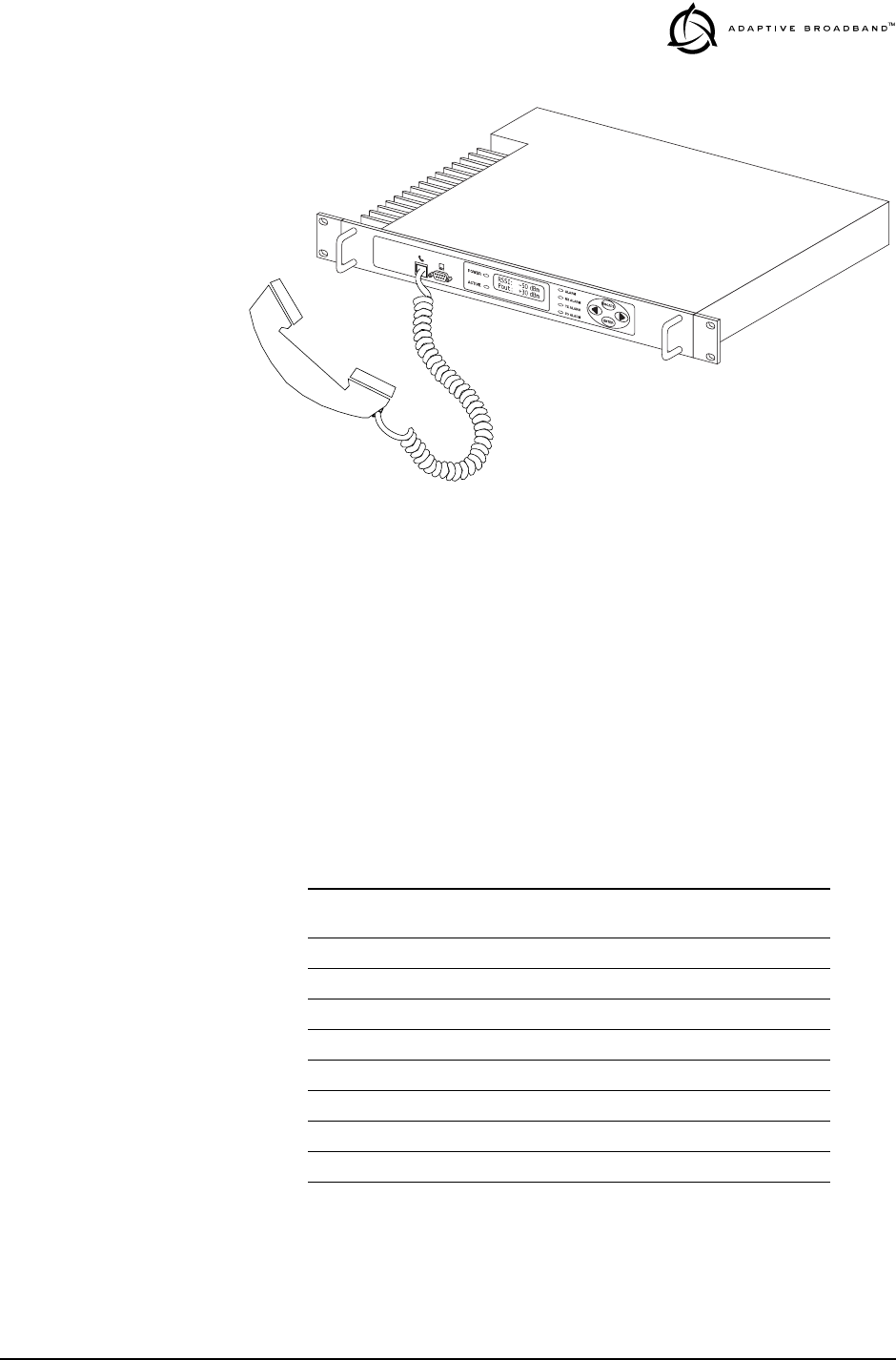
MDS 05-3627A01, Rev. A LEDR “S” Series I/O Guide 61
Invisible place holder
Figure 15. Orderwire Connection
3.7 Bandwidths, Data Rates and Modulation Types
The available bandwidth is permanently configured at the factory and
cannot be changed by the user. However, the modulation type and data
rate can be changed provided the bandwidth is sufficient to support the
modulation type and data rate. Table 17 shows the combinations of
radio bandwidth, data rates and modulation types that are available at
the time of publication.
Use of the modem command (page 51) automatically determines if the
combination of data rate, bandwidth and modulation type is allowable.
Table 17. Bandwidth vs. Modem Selection
Radio
Bandwidth Modem
Selection Data Rate(s) Modulation
25 kHz B1 64 kbps 16-QAM
50 kHz A1 64 kbps QPSK
50 kHz B2 128 kbps 16-QAM
100 kHz A2 128 kbps QPSK
100 kHz B3 256 kbps 16-QAM
200 kHz A3 256 QPSK
200 kHz B4, B5 384, 512 kbps 16-QAM
200 kHz C6 768 kbps 32-QAM
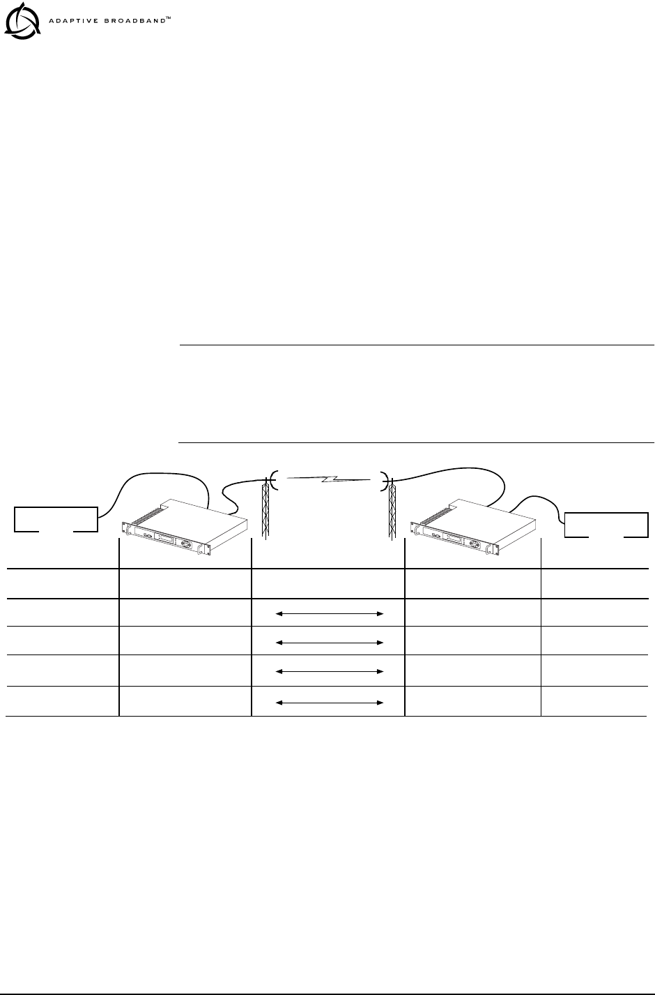
62 LEDR “S” Series I/O Guide MDS 05-3627A01, Rev. A
3.8 Transmit Clock Selection
The transmit clock selection must be addressed for every radio in every
installation. The single most important consideration is that there be
only one master clock in the radio network. The master clock can origi-
nate from the radio or from the Customer Premise Equipment (CPE).
The radio is capable of several different clocking modes. Refer to
Figure 16, Figure 17 and Figure 18 for typical system clocking
methods.
Refer to the Clock Mode screen description on page 27 for setting the
radio transmit clocking from the front panel. Refer to the clkmode
description on page 42 for setting the radio transmit clocking mode from
the console port.
NOTE: When customer premises equipment (CPE) is operated in
looped clock mode, it is recommended that the radio not be set
to line clock mode. To do so may cause the transmitting radio’s
PLL to be pulled out-of-lock, especially when operating at 4E1
data rates.
Invisible place holder
Figure 16. E1/T1 and Fractional Clocking Arrangements
(Between computing equipment unless both devices at the ends of the
link are driven by a common clock source)
Over-the-Air RF Path
Network Line 1, 2, 3, 4 Remote Looped Clock
CPE
Customer Premises
Equipment (CPE) LEDR Radio
Clock Source
CPE
Network* Line 1, 2, 3, 4 Line 1, 2, 3, 4 Network
Looped Clock Internal Clock Remote Looped Clock
Internal Clock Line 1, 2, 3, 4 Remote Looped Clock
Customer Premises
Equipment (CPE)
SITE A SITE B
* This mode suitable for most voice applications. It is not recommended for data transmission between computing equipment.
LEDR Radio
Clock Source
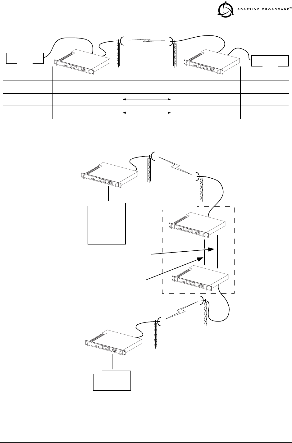
MDS 05-3627A01, Rev. A LEDR “S” Series I/O Guide 63
Invisible place holder
Figure 17. EIA-530 Clocking Arrangements
Invisible place holder
Figure 18. Typical Repeater Clocking Arrangement
(no multiplexer at repeater site)
Over-the-Air RF Path
CPE
Customer Premises
Equipment (CPE) LEDR Radio
Clock Source
CPE
Internal Clock External Clock Looped Clock External Clock
External Clock Internal Clock Looped Clock External Clock
Customer Premises
Equipment (CPE)
SITE A SITE B
LEDR Radio
Clock Source
CPE
REPEATER NULL-MODEM
DATA INTERCONNECT CABLE
ETHERNET CROSS-CABLE
REPEATER SITE
CPE
SITE A
SITE B
SITE C
LEDR Radio
Clock Source: Remote
LEDR Radio Clock
Source: Line 1, 2, 3, 4
LEDR Radio
Clock Source: Remote
Network or
Internal Clock
Looped Clock
Mode
Scenario 1:
LEDR Radio Clock
Source: Internal
Scenario 2:
Scenario 1:
Scenario 2:
Looped Clock
Mode
LEDR Radio Clock
Source: Line 1, 2, 3, 4
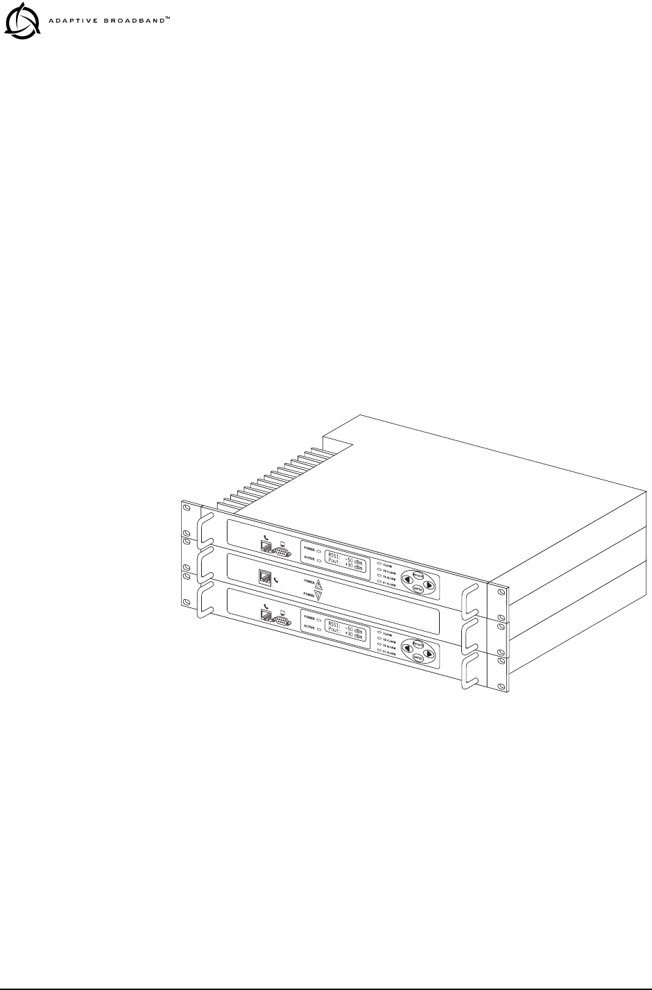
64 LEDR “S” Series I/O Guide MDS 05-3627A01, Rev. A
3.9 Protected (1+1) LEDR Radio
The LEDR radio may also be supplied in a Protected (redundant) con-
figuration (Figure 19). The protected version is designed to perform
automatic switchover to a second radio in the event of a failure in the
primary unit.
Protected operation is important for many mission critical or revenue
producing links. By configuring two identical LEDR radios in parallel
and including a third switch box containing the RF switching circuits
and the customer interfaces, it is possible to protect against failure in any
of the LEDR radio sub-systems, either through malfunction or external
environmental effects such as multipath fading or nearby lightning
strikes.
A Protected station consists of two standard LEDR radios and a Pro-
tected Switch Chassis (center unit in Figure 19). Ordinarily, the three
chassis are mounted together in a “stacked” arrangement as shown.
Invisible place holder
Figure 19. LEDR Radio Protected Version
Protected Operation
During normal operation, one radio path is selected and the RF and
interface switches are set to service that path. (An LED indicator on the
front panel of the Protected Switch Chassis shows the active unit.) A
switch on the transmitter circuitry allows one transmitter to be con-
nected to the antenna port. On the receive path, a coupler allows both
radio receivers to detect the receive signal.

MDS 05-3627A01, Rev. A LEDR “S” Series I/O Guide 65
Transmitter Failure Any failure on the "active" transmitter path will raise a fault condition
causing the transmit switch to change and the "standby" transmitter to
become the "active" unit. Fault conditions can be programmed from the
Network Management System (NMS) software, and can be parameters
such as:
• Low transmitter power
• High transmitter temperature
• Synthesizers out of lock
• Problem with the option board or framers
• CPU failure wherein the CPU watchdog causes a reset
• Fan fault
The newly "active" transmit path will remain in use until a manual
changeover returns the configuration to the original transmitter path.
This allows the link to remain fully operational until the user has
replaced the faulty transmitter circuitry.
Receiver Failure Both receivers are fed via an RF splitter from the antenna port. Both
receive paths are buffered and monitored for receive signal integrity via
uncorrectable bit errors. If the "active" receive circuitry fails, uncorrect-
able bit errors will be detected. The modem receive switch will first
determine that the "standby" receive path is operational (no uncorrect-
able bit errors) and will switch accordingly.
The protected LEDR radio is available with a number of configuration
options, each designed to optimize particular system solutions:
•1+1 operation - warm or hot standby: In a warm standby link,
the standby transmitter is powered down. In a hot standby link,
the standby transmitter is powered up and transmitted in a
dummy load. The warm standby option offers the advantages of
significantly reduced power consumption, since only one trans-
mitter path is powered. However, upon transmitter failure, the
switchover takes longer due to the transmitter having to be pow-
ered. Thus the hot standby offers the advantages of faster
switchover time and increased overall system availability.
•1+0 operation: In some applications the user wants the flexibil-
ity to offer protected (1+1) operation in the future, but operates
a critical link that cannot be decommissioned for the upgrade.
The 1+0 configuration provides a single LEDR radio wired
through the switch box. This configuration can be upgraded to
a full 1+1 protected radio by adding the second radio, without
taking the 1+0 radio out of commission and losing critical data.
•Symmetrical or asymmetrical receiver splitters: The default
protected radio is configured with a 3 dB splitter on the receive
path, meaning that each radio’s receiver signal level is equal,
but typically 4dB worse than an unprotected radio (3dB due to

66 LEDR “S” Series I/O Guide MDS 05-3627A01, Rev. A
splitter, plus 1dB cabling and additional connectors). As an
option, an asymmetrical splitter (1dB / 10dB) is offered. Using
this option, the active path is 2 dB stronger than with a symmet-
rical splitter (1dB compared to 3dB splitter loss), allowing for a
better fade margin and increased system availability during nor-
mal operation.
However, upon receiver change over, the receive signal strength
will be significantly reduced due to the 10dB of splitter loss
rather than the equal splitter’s 3dB loss, making the link more
prone to fades in this temporary changed over state. Providing
the failed standby receiver is replaced within a short period of
time, many users find that the asymmetric splitter’s increased
normal performance offsets any derating in the temporary
switched state.
Space Diversity Operation
Space diversity operation is an effective mechanism of increasing a
radio link’s resilience to transmission impairments such as multipath
fading or frequency selective fading. In difficult transmission environ-
ments such as over highly reflective and moving water paths, or in arid
environments where atmospheric ducting occurs, space diversity is the
most effective way of maintaining a continuous radio link.
In a space diversity link, two radio receivers are operated in parallel,
from two separate antennas mounted several wavelengths apart verti-
cally on the antenna tower. The separation of antennas is such that when
one antenna experiences fading due to multi-path interference, the other
antenna, being several wavelengths away, will not experience the same
fade. Thus, one receive path may experience uncorrectable errors, while
the other path will be error free. Similar to the protected operation, the
receive modem switch will determine which buffered data path is oper-
ating with the highest integrity, and select that path without inducing
any additional bit errors into the link.
Space diversity is especially effective in changeable multi-path environ-
ments such as over tidal water paths. Since water is highly reflective,
there will be continual "constructive" and "destructive" interference at
each single antenna over the course of the day as the water rises and falls
and the reflected water path interferes with the line-of-sight path. By
correct vertical positioning of the antennas, these effects can be negated,
allowing one antenna to see a good signal while the other is experi-
encing fading, and the modem switching accordingly to allow the link
to operate error- free.
The space diversity LEDR radio is available only in a hot standby con-
figuration, with a symmetrical 3dB coupler on the receive paths.

MDS 05-3627A01, Rev. A LEDR “S” Series I/O Guide 67
User Interface & Control
Protected operation is configured using the Redundant screen (page 34)
on either radio front panel, or with the rdnt command from a console ter-
minal (see page 52).
3.10 Fractional T1 Interface Card (Optional
Equipment)
The fractional T1 interface (FT1) option (P/N 03-3846A01) provides
additional connectivity within a LEDR network. The installation of an
FT1 option board inside the radio allows the standard EIA-530 customer
data interface to be bypassed and connection directly to a G.703 T1
interface.
With the FT1 option, users are able to place a LEDR link from a network
service access point to a remote site, where an installation supports mul-
tiple communications devices. Direct interface to customer equipment
such as channel banks is possible without the use of expensive protocol
converters.
See “Field Installation of FT1 Option Board Non-protected:
03-3846A01 Protected: 03-3539A01” on page 78 for instructions on
adding this option to a LEDR radio.
Fractional T1 Performance
The FT1 option allows the LEDR radio to be connected directly with a
G.703 T1 interface. The line rate of the interface operates at the T1 rate
of 1.544 Mbps. Twelve user selectable DS-0 timeslots are transmitted
over the air in the maximum FCC / IC allowed 200 kHz occupied band-
width in the 960 MHz FCC / IC frequency band. The T1 interface is
G.703 at 100 Ω line impedance. Physical connection is via an RJ48C
jack on the rear panel.
Configurable
Parameters The following performance specifications of the T1 fractional interface
are adjustable by the user. All of these parameters are manageable
locally, or over the air via SNMP network management. (Refer to the
SNMP Handbook, P/N 05-3532A01 for more information.)
Timeslots and Framing—Twelve DS-0 timeslots are permitted, with
selection arbitrary. The selection of timeslots may be different at each
end of the link, provided their number is equal. The timeslots may not
be reordered.
Alarm signals RAI and AIS are generated as appropriate. The user may
optionally have these signals forwarded over the RF link.
The frame format is selectable among: FT only, ESF without CRC
checking and generation, SF (D4), SF with JYEL indication, ESF with
CRC checking and generation.

68 LEDR “S” Series I/O Guide MDS 05-3627A01, Rev. A
The re-framing criteria may be adjusted to the following settings: 2 out
of 4 Fbit errors, 2 out of 5 Fbit errors, 2 out of 6 Fbit errors.
Line Codes—Standard T1 line codes are supported: B8ZS, AMI, and
per-channel B7ZS.
Diagnostics The T1 line at each end of the link may be tested using a variety of bit
patterns. In normal operation, statistics are stored for any errors occur-
ring at the line interface, such as framing errors, bipolar violations, and
CRC errors.
Data may be looped back at the local port, through the T1 option only,
and at the remote unit. Further, the unit will respond to in-band (SF) and
data link (ESF) loopback codes at the local port.
When in ESF framing mode, the option can automatically generate per-
formance report messages.
The following alarms may be monitored & logged. They may also be
associated with a user-selectable indication (alarm contact or front panel
LED): Remote Loopback, Lost Frame, Lost Signal, Lost Analog Signal,
AIS, RAI (RYEL), MultiFrame RAI, Severely Errored Frame, Frame
Re-Align, MultiFrame AIS, Far End Block Error, Line Code Error, CRC
Errors and Frame Bit Error.
Clocking—The clock source is configurable for network, loopback, and
internal timing, with secondary selections available should the primary
source become faulty.
4.0 RADIO EVENT CODES
Table 18 lists the event codes that may be encountered during operation
of the radio. These codes may be read from a console terminal using the
events pending command. (See page 43 for a full description of the events
command.)
NOTE: The event codes listed here are available on radios equipped
with an FT1 Option Board. Standard “S” Series radios will
display fewer codes.
Table 18. Event Codes
ID EVENT NAME DESCRIPTION DEFAULT
LED SNMP
TRAP
LEVEL
0 EXT_ALARM_IN1 External Alarm Input #1 ALARM CRITICAL
1 EXT_ALARM_IN2 External Alarm Input #2 ALARM CRITICAL
2 EXT_ALARM_IN3 External Alarm Input #3 ALARM CRITICAL
3 EXT_ALARM_IN4 External Alarm Input #4 ALARM CRITICAL
4 MODULATOR_EV Communication failure
with modulator ALARM CRITICAL

MDS 05-3627A01, Rev. A LEDR “S” Series I/O Guide 69
5 DEMODULATOR_EV Communication failure
with demodulator ALARM CRITICAL
6 MOD_SELFTEST Modulator selftest failed NONE CRITICAL
7 DEMOD_SELFTEST Demodulator selftest
failed NONE INFORM
8 PERM_REGN_CHECKSUM Permanent region
checksum failed NONE INFORM
9 APP1_REGN_CHECKSUM Application #1 checksum
failed NONE INFORM
10 APP2_REGN_CHECKSUM Application #2 checksum
failed NONE INFORM
11 BOOT_REGN_CHECKSUM Boot loader checksum
failed NONE INFORM
12 CONF1_REGN_CHECKSUM Configuration Data region
#1 checksum failed NONE INFORM
13 CONF2_REGN_CHECKSUM Configuration Data region
#2 checksum failed NONE INFORM
14 RTC_TEST Real-time clock error NONE INFORM
15 BBRAM_TEST NV-RAM test failed NONE INFORM
16 BATTERY_LOW NV-RAM battery is low ALARM MAJOR
17 TX_SYNTH_LOCK Transmit Synthesizer
out-of-lock TXALARM CRITICAL
18 RX_SYNTH_LOCK Receive Synthesizer
out-of-lock RXALARM CRITICAL
19 DIG_POWER_REF Digital Power Reference
is out of specified range ALARM CRITICAL
20 TEMPERATURE Temperature sensor
reads over 80 degrees
Celsius
ALARM CRITICAL
21 TX_POWER_LOOP Transmit Power Loop is
out-of-lock TXALARM MAJOR
22 DEMOD_SNR_LOW Demodulator
Signal-to-Noise ratio is
unacceptably low
NONE MINOR
23 DEMOD_AGC_RSSI Demodulator Automatic
Gain Controlled RSSI too
low
NONE MINOR
24 DEMOD_FEC_RECOVER FEC circuitry has detected
and corrected one or more
errors
NONE MINOR
25 DEMOD_FEC_UNRECOVER FEC circuitry has detected
one or more uncorrectable
errors
NONE MINOR
26 DEMOD_MULTIPATH Excessive multipath
distortion detected NONE MINOR
27 DEMOD_ACQUISITION Demodulator lost sync.
lock on received signal RXALARM CRITICAL
Table 18. Event Codes (Continued)
ID EVENT NAME DESCRIPTION DEFAULT
LED SNMP
TRAP
LEVEL

70 LEDR “S” Series I/O Guide MDS 05-3627A01, Rev. A
28 TX_TO_REMOTE_RX Problem with link between
the local transmitter &
remote Rx
ALARM CRITICAL
29 REDUNDANT_ALARM Problem with redundant
unit ALARM CRITICAL
30 WDOG_TIME_OUT Processor watchdog has
expired and reset the
processor
ALARM CRITICAL
31 RX_OFF Radio is not receiving due
to a weak signal or
equipment failure
RXALARM CRITICAL
32 SOFTWARE_TX_OFF Software command has
unkeyed the radio TXALARM CRITICAL
33 RTC_NOT_SET The real time clock is not
programmed NONE MINOR
34 IO1_DIG_LOC_lOOPBACK The radio’s 530 or TELCO
I/O port is in Digital local
loopback mode
NONE INFORM
35 IO2_DIG_LOC_lOOPBACK The radio’s 2nd TELCO
I/O port is in Digital local
loopback mode
NONE INFORM
36 IO3_DIG_LOC_lOOPBACK The radio’s 3rd TELCO
I/O port is in Digital local
loopback mode
NONE INFORM
37 IO4_DIG_LOC_lOOPBACK The radio’s 4th TELCO
I/O port is in Digital local
loopback mode
NONE INFORM
38 RF_LOCAL_LOOPBACK The radio is in Local RF
loopback test mode NONE INFORM
39 IO1_DIG_REM_LOOPBACK The radio’s 530 or TELCO
I/O port is in Digital
Remote loopback mode
NONE INFORM
40 IO2_DIG_REM_LOOPBACK The radio’s 2nd TELCO
I/O port is in Digital
Remote loopback mode
NONE INFORM
41 IO3_DIG_REM_LOOPBACK The radio’s 3rd TELCO
I/O port is in Digital
Remote loopback mode
NONE INFORM
42 IO4_DIG_REM_LOOPBACK The radio’s 4th TELCO
I/O port is in Digital
Remote loopback mode
NONE INFORM
43 RAW_SERVICE_CHANNEL The Raw Service Channel
data frame is exhibiting
error
ALARM MAJOR
44 ATOD_REFERENCE A fault is detected with the
Analog to Digital converter ALARM CRITICAL
45 NEW_CONFIG_REV A new revision of
configuration data
structure has been
detected
NONE INFORM
Table 18. Event Codes (Continued)
ID EVENT NAME DESCRIPTION DEFAULT
LED SNMP
TRAP
LEVEL

MDS 05-3627A01, Rev. A LEDR “S” Series I/O Guide 71
46 FPGA_LOAD FPGA is not loaded
correctly NONE INFORM
47 DATE_TIME_CHANGE The date or time is been
modified NONE INFORM
48 HARDWARE_TX_OFF The transmitter key
hardware is in an unkeyed
state
TXALARM CRITICAL
49 INACTIVE_ON Current transceiver is in
standby mode when in
protected radio chassis
ALARM MAJOR
50 NO_OPTION_UNIT No Option Card is
detected NONE INFORM
51 VOCODER_INIT_ERR The voice processor
initialization failed ALARM MAJOR
52 VOCODER_ERROR The voice processor is
reporting a problem ALARM MAJOR
53 POWER_ON_RESET This indicates PowerOn
Reset Cycle NONE INFORM
54 EXT_HARD_RESET This indicates last
Power-Up Cycle was due
to External Hard Reset
NONE INFORM
55 EXT_SOFT_RESET This indicates last
Power-Up Cycle was due
to External Soft Reset
NONE INFORM
56 INACT_CONFIG_SYNC Protected 1+1 mode
Active to Inactive
Configuration data sync.
error
ALARM CRITICAL
57 NEW FIRMWARE LOADED New firmware has been
downloaded from flash
memory.
NONE INFORM
58 CONFIG_CHANGED The transceiver
configuration has been
modified
NONE INFORM
59 SELFTEST_COMPLETE A self test has completed
execution NONE INFORM
60 PERFORM_DEGRADED A performance
degradation threshold has
been exceeded
ALARM INFORM
61 DUPLICATE_UNIT_ID Another unit with the
same unit ID has been
detected
ALARM INFORM
62 LINK_UNAVAILABLE The G821 status indicates
that the link is unavailable NONE INFORM
63 EVENT_LOG_CLEARED The event log has been
cleared NONE INFORM
64 FAN1_TROUBLE There is a problem with
the fan ALARM INFORM
Table 18. Event Codes (Continued)
ID EVENT NAME DESCRIPTION DEFAULT
LED SNMP
TRAP
LEVEL

72 LEDR “S” Series I/O Guide MDS 05-3627A01, Rev. A
65 Reserved for future use ———
66 USER_REBOOT The user has rebooted the
radio NONE INFORM
67 MODEM_LOCAL_LOOPBACK Modulator data path is
locally looped back to
Demodulator.
NONE INFORM
68 MODEM_REMOTE_LOOPBA
CK Demodulator data path is
looped back to modulator
for remote radio loopback
application
NONE INFORM
69 OPT_MUX_LOOBACK Option card multiplexed
data path from Line(s) is
looped back.
NONE INFORM
70 IO1_REM_LOOPBACK_SERV Radio is server for remote
radio loopback mode with
its payload data at Line IO
#1 looped back to the
commanding local radio.
NONE INFORM
71 IO2_REM_LOOPBACK_SERV Radio is server for remote
radio loopback mode with
its payload data at Line IO
#2 looped back to the
commanding local radio.
NONE INFORM
72 IO3_REM_LOOPBACK_SERV Radio is server for remote
radio loopback mode with
its payload data at Line IO
#3 looped back to the
commanding local radio.
NONE INFORM
73 IO4_REM_LOOPBACK_SERV Radio is server for remote
radio loopback mode with
its payload data at Line IO
#4 looped back to the
commanding local radio.
NONE INFORM
74 IO1_RECVR_LOF Line IO #1 receiver
Loss-of-framing alarm. I/O ALARM CRITICAL
75 IO1_RECVR_LOS Line IO #1 receiver
Loss-of-signal alarm. I/O ALARM CRITICAL
76 IO1_RECVR_ALOS Line IO #1 receiver
Loss-of-analog-signal
alarm.
I/O ALARM CRITICAL
77 IO1_RECVR_AIS Line IO #1 receiver
detected AIS alarm. I/O ALARM CRITICAL
78 IO1_RECVR_RAI Line IO #1 receiver
detected RAI (yellow)
alarm.
I/O ALARM CRITICAL
79 IO1_RECVR_MRAI Line IO #1 receiver
detected multi-framed RAI
(yellow) alarm.
I/O ALARM CRITICAL
80 IO1_RECVR_SEF Line IO #1 receiver
detected Severely Errored
Frames.
I/O ALARM CRITICAL
Table 18. Event Codes (Continued)
ID EVENT NAME DESCRIPTION DEFAULT
LED SNMP
TRAP
LEVEL

MDS 05-3627A01, Rev. A LEDR “S” Series I/O Guide 73
81 IO1_RECVR_COFA Line IO #1 receiver
detected
Change-of-Frame-
Alignment alarm.
I/O ALARM CRITICAL
82 IO1_RECVR_MAIS Line IO #1 receiver
detected multi-framed AIS
alarm.
I/O ALARM CRITICAL
83 IO1_RECVR_FEBE Line IO #1 receiver
detected E1
Far-End-Block-Errors
alarm.
I/O ALARM INFORM
84 IO1_RECVR_LCV Line IO #1 receiver
detected Line-Code-
Violation alarm.
I/O ALARM INFORM
85 IO1_RECVR_CRC Line IO #1 receiver
detected CRC alarm. I/O ALARM INFORM
86 IO1_RECVR_FBIT Line IO #1 receiver
detected Frame Bit Error. I/O ALARM INFORM
87 IO2_RECVR_LOF Line IO #2 receiver
Loss-of-framing alarm. I/O ALARM CRITICAL
88 IO2_RECVR_LOS Line IO #2 receiver
Loss-of-signal alarm. I/O ALARM CRITICAL
89 IO2_RECVR_ALOS Line IO #2 receiver
Loss-of-analog-signal
alarm.
I/O ALARM CRITICAL
90 I02_RECVR_AIS Line IO #2 receiver
detected AIS alarm. I/O ALARM CRITICAL
91 IO2_RECVR_RAI Line IO #2 receiver
detected RAI (yellow)
alarm.
I/O ALARM CRITICAL
92 IO2_RECVR_MRAI Line IO #2 receiver
detected multi-framed RAI
(yellow) alarm.
I/O ALARM CRITICAL
93 IO2_RECVR_SEF Line IO #2 receiver
detected Severely Errored
Frames.
I/O ALARM CRITICAL
94 IO2RECVR_COFA Line IO #2 receiver
detected
Change-of-Frame-
Alignment alarm.
I/O ALARM CRITICAL
95 IO2_RECVR_MAIS Line IO #2 receiver
detected multi-framed AIS
alarm.
I/O ALARM CRITICAL
96 IO2_RECVR_FEBE Line IO #2 receiver
detected E1
Far-End-Block-Errors
alarm.
I/O ALARM INFORM
Table 18. Event Codes (Continued)
ID EVENT NAME DESCRIPTION DEFAULT
LED SNMP
TRAP
LEVEL

74 LEDR “S” Series I/O Guide MDS 05-3627A01, Rev. A
97 IO2_RECVR_LCV Line IO #2 receiver
detected
Line-Code-Violation
alarm.
I/O ALARM INFORM
98 IO2_RECVR_CRC Line IO #2 receiver
detected CRC alarm. I/O ALARM INFORM
99 IO2_RECVR_FBIT Line IO #2 receiver
detected Frame Bit Error. I/O ALARM CRITICAL
100 IO3_RECVR_LOF Line IO #3 receiver
Loss-of-framing alarm. I/O ALARM CRITICAL
101 IO3_RECVR_LOS Line IO #3 receiver
Loss-of-signal alarm. I/O ALARM CRITICAL
102 IO3_RECVR_ALOS Line IO #3 receiver
Loss-of-analog-signal
alarm.
I/O ALARM CRITICAL
103 IO3_RECVR_AIS Line IO #3 receiver
detected AIS alarm. I/O ALARM CRITICAL
104 IO3_RECVR_RAI Line IO #3 receiver
detected RAI (yellow)
alarm.
I/O ALARM CRITICAL
105 IO3_RECVR_MRAI Line IO #3 receiver
detected multi-framed RAI
(yellow) alarm.
I/O ALARM CRITICAL
106 IO3_RECVR_SEF Line IO #3 receiver
detected Severely Errored
Frames.
I/O ALARM CRITICAL
107 IO3_RECVR_COFA Line IO #3 receiver
detected
Change-of-Frame-
Alignment alarm.
I/O ALARM CRITICAL
108 IO3_RECVR_MAIS Line IO #3 receiver
detected multi-framed AIS
alarm.
I/O ALARM CRITICAL
109 IO3_RECVR_FEBE Line IO #3 receiver
detected E1
Far-End-Block-Errors
alarm.
I/O ALARM INFORM
110 IO3_RECVR_LCV Line IO #3 receiver
detected Line-Code-
Violation alarm.
I/O ALARM INFORM
111 IO3_RECVR_CRC Line IO #3 receiver
detected CRC alarm. I/O ALARM INFORM
112 IO3_RECVR_FBIT Line IO #3 receiver
detected Frame Bit Error. I/O ALARM INFORM
113 IO4_RECVR_LOF Line IO #4 receiver
Loss-of-framing alarm. I/O ALARM CRITICAL
114 IO4_RE CVR_LOS Line IO #4 receiver
Loss-of-signal alarm. I/O ALARM CRITICAL
Table 18. Event Codes (Continued)
ID EVENT NAME DESCRIPTION DEFAULT
LED SNMP
TRAP
LEVEL

MDS 05-3627A01, Rev. A LEDR “S” Series I/O Guide 75
115 IO4_RECVR_ALOS Line IO #4 receiver
Loss-of-analog-signal
alarm.
I/O ALARM CRITICAL
116 IO4_RECVR_AIS Line IO #4 receiver
detected AIS alarm. I/O ALARM CRITICAL
117 IO4_RECVR_RAI Line IO #4 receiver
detected RAI (yellow)
alarm.
I/O ALARM CRITICAL
118 IO4_RECVR_MRAI Line IO #4 receiver
detected multi-framed RAI
(yellow) alarm.
I/O ALARM CRITICAL
119 IO4_RECVR_SEF Line IO #4 receiver
detected Severely Errored
Frames.
I/O ALARM CRITICAL
120 IO4_RECVR_COFA Line IO #4 receiver
detected
Change-of-Frame-
Alignment alarm.
I/O ALARM CRITICAL
121 IO4_RECVR_MAIS Line IO #4 receiver
detected multi-framed AIS
alarm.
I/O ALARM CRITICAL
122 IO4_RECVR_FEBE Line IO #4 receiver
detected E1
Far-End-Block-Errors
alarm.
I/O ALARM INFORM
123 IO4_RECVR_LCV Line IO #4 receiver
detected
Line-Code-Violation
alarm.
I/O ALARM INFORM
124 IO4_RECVR_CRC Line IO #4 receiver
detected CRC alarm. I/O ALARM INFORM
125 IO4_RECVR_FBIT Line IO #4 receiver
detected Frame Bit Error. I/O ALARM INFORM
126 DIG_REM_LOOPBACK For EIA-530, local radio is
in remote loopback mode NONE INFORM
127 SERV_REM_LOOPBACK For EIA-530, local radio
(as remote server) is
serving remote loopback
mode.
NONE INFORM
128 BAD_CLKMODE Line framers detected bad
clock mode configuration. NONE INFORM
Table 18. Event Codes (Continued)
ID EVENT NAME DESCRIPTION DEFAULT
LED SNMP
TRAP
LEVEL

76 LEDR “S” Series I/O Guide MDS 05-3627A01, Rev. A
5.0 FIELD REPROGRAMMING
The LEDR radio’s firmware can be upgraded with new software
releases that may be issued from time to time by Adaptive Broad-
band/MDS. Reprogramming can be done serially through the front
panel console port or over a network connection via TFTP. The
TFTP method provides a way of downloading to the radio without being
physically at the radio’s location.
To support firmware upgrades while the radio is in use, the LEDR radio
contains two complete copies of its firmware. Once the download is
complete, the radio can be rebooted using the new code. However, if an
error occurs during the download, the radio can easily recover because
it always has a complete copy of firmware available.
The steps below explain how to program new firmware into the radio
using both the console port and TFTP methods.
5.1 Reprogramming via the Console Port
Set Up
Connect a PC to the radio’s front panel console port using a 9-pin
RS-232 cable. (See Figure 23 on page 85 for cable wiring details.)
Download Procedure
1. Start the FlashUtil Windows application available from Adaptive
Broadband/MDS. From the View|Options menu, select the
appropriate com port and baud rate.
2. Ensure that autobaud is enabled (see lower right corner of the
FlashUtil window). From the View menu, select console. This will
bring up a console window to the LEDR radio. At the ADAP>
prompt, enter a login name and password and then close the console.
3. Using the File|Open dialog, select the directory where the new firm-
ware is located. In the file window, highlight the correct (.mpk) file
and then press the green start arrow.
Verification and Reboot
To verify the new code, open the console again by pressing Alt + L.
Enter boot to determine which image is currently active. This command
will respond as follows:
boot: Image 1 is Active or: boot: Image 2 is Active

MDS 05-3627A01, Rev. A LEDR “S” Series I/O Guide 77
The new firmware is downloaded into the inactive image. Therefore, if
the radio responded Image 1 is Active, enter iverify 2, otherwise, enter
iverify 1. The radio will respond indicating whether or not the image has
been verified. If the image does not verify, try downloading the code
again. If the download fails after repeated attempts, the hardware may
be damaged. For a replacement board please contact the factory using
the information given at the back of this manual.
NOTE: The following paragraph describes rebooting the radio. This
action will disrupt the communications link.
Once the image has been verified, the radio must be rebooted using the
new firmware. This is done by entering the command boot 1 or boot 2,
where the 1 or 2 corresponds with the image number used with the iverify
command above.
Once the radio has rebooted and displays the ADAP> prompt again, the
firmware can be downloaded or copied into the other image. Often,
copying the firmware from one image to the other can be faster than per-
forming a second download. To copy the firmware over to the other
image, simply enter icopy. The radio will prompt you for confirmation
(y/n) and then begin copying.
5.2 Reprogramming via a Network Connection
Set Up
Connect the LEDR radio’s ETHERNET NMS connector to a PC via a net-
work connection This can be done in one of three ways: 1) by con-
necting both the radio and the PC to a network hub, 2) by connecting
them directly through an ethernet cross-over cable, or 3) by connecting
them to a common LAN.
If the radio is near the PC, an RS-232 cable can be connected between
them in order to run the console commands. However, if the radio is
some distance away, such as at a remote site, telnet or rlogin can be used
to execute the necessary commands.
Download Procedure
1. Log in to the radio using the login command. Use the ip command to
ensure that the radio has a valid IP address.
2. "Ping" the radio from the PC to ensure that the PC and the radio
have valid routes to pass information between them.
3. Start a TFTP server application on the PC. At the radio’s ADAP>
prompt, start the download by entering reprogram network [filename]
[PC’s IP Address]. The download can be monitored from the radio by

78 LEDR “S” Series I/O Guide MDS 05-3627A01, Rev. A
entering reprogram status. When the download is complete the radio
will emit two short beeps and the response from reprogram status will
indicate that the download has finished.
SNMP Option The TFTP download process can also be initiated using an SNMP man-
ager. The Firmware|FwProgTable object provides a means for specifying
the TFTP server IP address and the filename for the firmware.
Verification and Reboot
When the download is complete, verify the code and reboot the radio as
described under Verification and Reboot in Paragraph 5.1 above.
6.0 FIELD REPLACEABLE UNITS
The Field Replaceable Units and their part numbers are listed below.
Field servicing or replacement of PC boards and assemblies should be
performed by qualified service personnel.
When ordering parts from the factory, always give the complete model
number of the radio. Refer to the inside rear cover of this guide for con-
tact information.
• Transceiver Main PCB, 400S (P/N 03-3820Axx)
• Transceiver Main PCB, 900S (P/N 03-3810Axx)
• Transceiver Main PCB, 1400S (P/N 03-3830Axx)
• “FT1” Option Board—Non-protected (P/N 03-3846A01)
• “FT1” Option Board—Protected (P/N 03-3539A01)
• Battery for Transceiver’s Backed-up SRAM (P/N 27-3109A01)
• Transceiver Front Panel Assembly (P/N 03-3815A01)
• Transceiver/Protected Sw. Chassis, Base (P/N 03-3810A01)
• Transceiver/Protected Sw. Chassis, Cover (P/N 03-3801A02)
• Duplexer (if equipped)—frequency dependent, contact factory
• Protected Switch Interface Board (P/N 03-3831Axx)
• Protected Switch Ethernet Hub Assy. (P/N 08-3809A01)
• Protected Switch Front Panel Assembly (P/N 03-3855A01)
6.1 Field Installation of FT1 Option Board
Non-protected: 03-3846A01
Protected: 03-3539A01
An “S” Series LEDR radio can be fitted with a Fractional T1 (FT1)
interface board (Figure 20). The addition of an FT1 board enables the
radio to operate with a G.703 interface at speeds up to 768 kbps.
To add the FT1 option board to an existing LEDR II radio, follow these
steps:
1. Remove the top cover of the radio (4 phillips screws).

MDS 05-3627A01, Rev. A LEDR “S” Series I/O Guide 79
2. Locate the installation area for the FT1 option board (see Figure 21).
Remove the three phillips screws on the main PC board which corre-
spond to the mounting holes on the FT1 option board.
3. Install the threaded standoff spacers (furnished with the option
board) onto the main PC board in the holes formerly occupied by the
screws. (Note: Washers must not be used between the standoff spac-
ers and either of the PC boards.)
4. Locate connectors J912 and J913 (see Figure 21). These connectors
mate with the plugs on the bottom of the FT1 option board.
5. Carefully set the option board into place, making sure to align the
mounting holes with the threaded standoffs on the main PCB. (The
FT1 rear panel connector should align with the rectangular cutout at
the radio’s rear panel, and the rear edge of the option board should
be parallel to the main PC board.)
6. Look under the right edge of the FT1 board to ensure that J912 is
aligned with the mating connector on the option board. With the
board properly aligned, push down firmly in the area directly above
J913 and then over J912 at the edge. A distinct “snapping” action
will be felt as the connectors engage.
7. Install the phillips mounting screws with lockwashers on the top of
the FT1 board.
For protected versions only: Install the plastic clip, if supplied, at the
right rear corner of the FT1 option board. It slips over the edge of
the main PC board and the option board. Gently tighten the hex
screw to secure the clamp.)
8. Re-install the radio’s top cover. This completes the FT1 board instal-
lation.
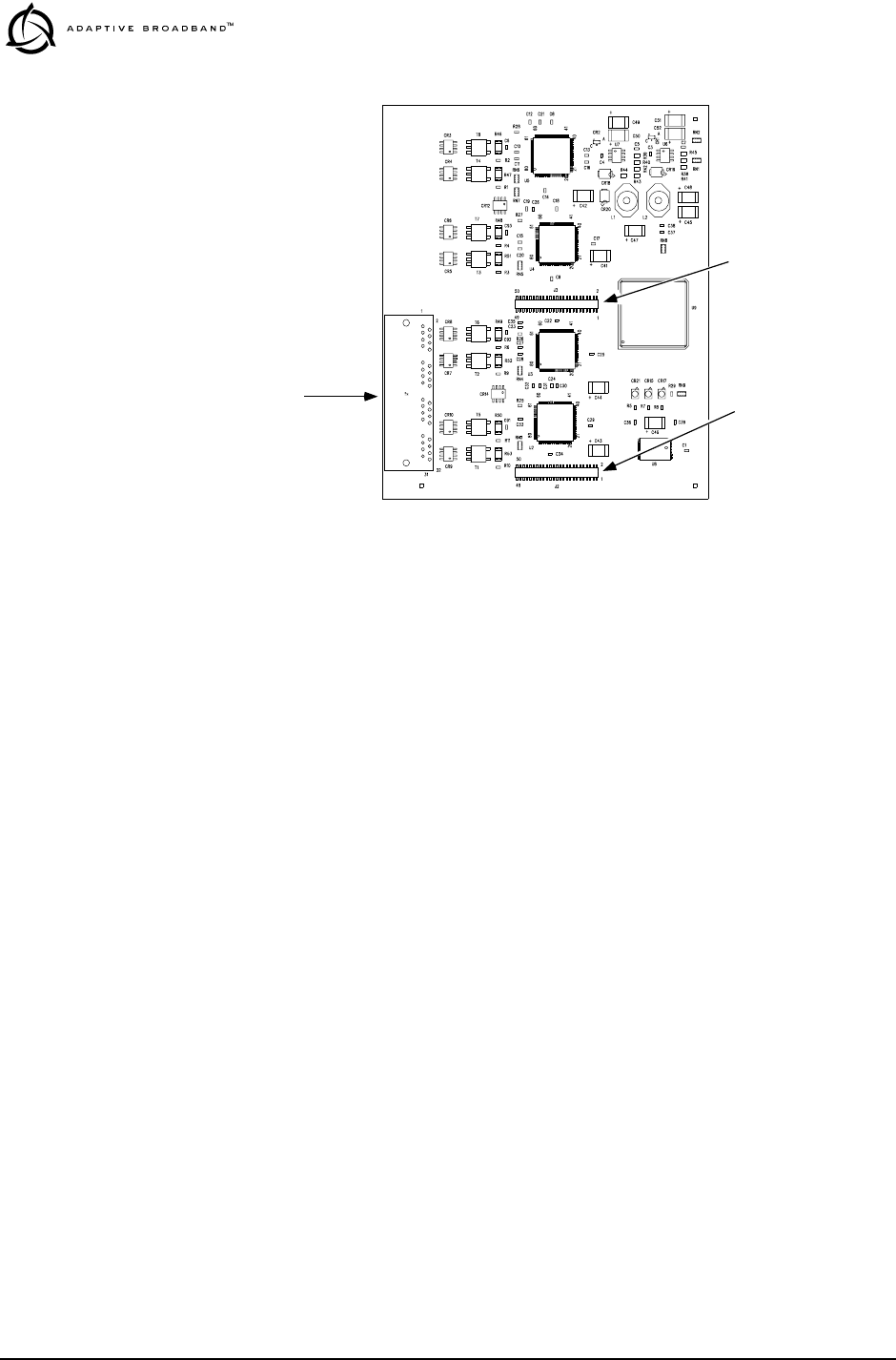
80 LEDR “S” Series I/O Guide MDS 05-3627A01, Rev. A
Invisible place holder
Figure 20. FT1 Option Board—Component Side
(03-3846A01 shown, 03-3539A01 similar)
User Interface
Ports Mates with J912 on
Radio PC Board
Mates with J913 on
Radio PC Board
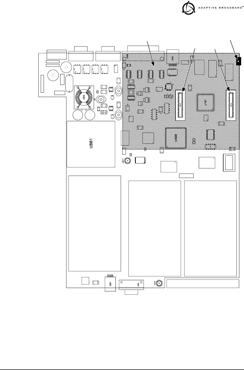
MDS 05-3627A01, Rev. A LEDR “S” Series I/O Guide 81
Invisible place holder
Figure 21. View of Radio PC Board
Showing Installation Details for FT1 Option Board
J912J913
REAR PANEL OF LEDR RADIO
Installation Area
for FT1 Option Board
PC Board Clamp
(Some Versions)

82 LEDR “S” Series I/O Guide MDS 05-3627A01, Rev. A
7.0 TECHNICAL REFERENCE
7.1 Specifications
General
Frequency Ranges: 330–512 MHz (LEDR 400S)
800 to 960 MHz (LEDR 900S)
1350–1535 MHz (LEDR 1400S)
Frequency Selection: Programmable within each frequency range
RF Occupied Bandwidth: Standard “S” Series radios: 25, 50, 100 and 200
kHz
User Data Rates: Standard “S” Series radios: 64, 128, 256, 384, 512,
768 kbps
With FT1 Option Board: n x 64 kbps
(Where n= 1,2,4,6,12)
Permitted Data Throughput: Standard “S” Series radios:
Channel Size Data Rate
25 kHz 64 kbps
50 kHz 64 kbps to 128 kbps
100 kHz 64 kbps to 256 kbps
200 kHz 64 kbps to 768 kbps
Modulation Type: 32 QAM, 16 QAM, QPSK
Forward Error Correction (FEC): Reed Solomon
Acquisition Time (typical): From power up, 10 seconds
Voltage Range: 24 Vdc or 48 Vdc (±20%)
Power Consumption: Less than 60 watts (non-protected configuration)
Less than 135 watts (protected configuration)
Temperature Range: -5° to 50° C
Humidity: ≤90% non-condensing @ 40° C
Size: 1RU, 19 Inch rack mount compatible
45 mm (1.75 in) high, 1RU
426 mm (16.75 in) wide (excluding rack brackets)
305 mm (12 in) deep
Transmitter
Transmit Power: +30 dBm (1 watt) at antenna port
Output Control Range: 0 dB to -10 dB
Frequency Stability: 1.5 ppm
Spurious Outputs: <-60 dBc (LEDR 400S)
<-60 dBm (LEDR 1400S)
<-60 dBc (LEDR 900S)

MDS 05-3627A01, Rev. A LEDR “S” Series I/O Guide 83
Receiver
Sensitivity (for 10-6 BER): Standard “S” Series radios:
Bandwidth Data Rate Sensitivity
25 kHz 64 kbps -101 dBm
50 kHz 128 kbps -98 dBm
100 kHz 256 kbps -95 dBm
200 kHz 768 kbps -92 dBm
Residual BER:: <1 x 10⁻¹⁰
Dynamic Range: >65 dB
Protected Switch Chassis
Transmitter Coupling Losses
(Typical): 2 dB
Receive Coupling Losses
(Typical): 4 dB (Symmetrical Splitter)
2 dB/10 dB (Asymmetrical Splitter)
Interfaces
Data: EIA-530
With FT1 Option: G.703
Orderwire: 600Ω balanced, DTMF capable
Data Service Channel: RS-232, 9600 bps
Ethernet: 10 Base-T
Console Port: RS-232, 9600 bps to 38.4 kbps
Alarms: 4 programmable outputs, 4 inputs
Antenna: 50Ω Impedance
Network Management
Element Management: Via built-in menu or command line interface
Optional SNMP Management: Using MIB II and custom enterprise MIB
Diagnostic Functions
Local LED Indicators
(front panel): Power, Active, General Alarm, Rx Alarm, Tx Alarm,
I/O Alarm
LCD Display Measurements: RSSI, RF Power, Signal-to-Noise ratio, BER
Loopback: Local and Remote
Agency Approvals (LEDR 400S)
Transmission: FCC Part 90
Environmental: ETS 300 019, Class 3.2
Industry Canada: RS-119
Safety: UL, CSA
EMC: ETS 300 385, FCC Part 15

84 LEDR “S” Series I/O Guide MDS 05-3627A01, Rev. A
:Agency Approvals (LEDR 900S)
Transmission: FCC Part 101
Environmental: ETS 300 019, Class 3.2
Industry Canada: 932 to 944 MHz in Canada
Safety: UL, CSA
EMC: ETS 300 385, FCC Part 15
Agency Approvals (LEDR 1400S)
Transmission: ETS 300 630, MPT 1717
Environmental: ETS 300 019, Class 3.2
EMC: ETS 300 385
Safety: CE Mark
Options (Consult factory for details)
Space Diversity, Hot-standby Protected, Warm-standby Protected, Bandwidth Upgrade
Kits
Accessories
110/240 Vac 50/60 Hz Power Supply, Orderwire Handset
NOTE: The factory reserves the right to make changes to this specification without ad-
vance notice or obligation to any person.
7.2 Pinout Information
Orderwire Invisible place holder
Figure 22. Orderwire Connector
1 2 3 4 5 6
RJ-45
p
Pin Signal Direction
1 + 12 Vdc Output
2 Ground —
3 Ear –Output
4 Ear + Output
5 Mouth Input
6 Ground —
RJ-11
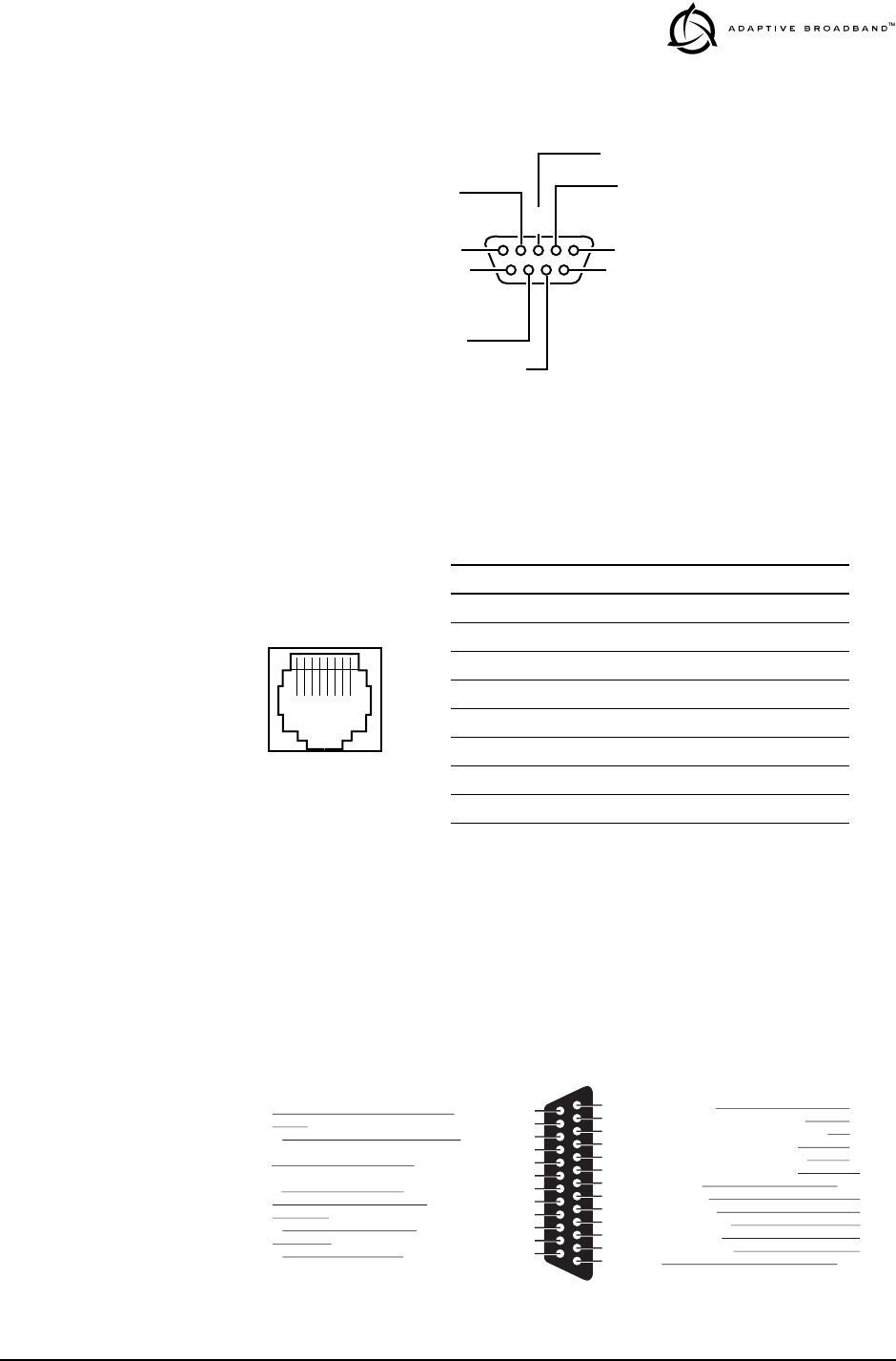
MDS 05-3627A01, Rev. A LEDR “S” Series I/O Guide 85
Console
Invisible place holder
Figure 23. Console Port DB-9 Female Pinout
Ethernet
Invisible place holder
Figure 24. Ethernet Connector
EIA-530-A Data
Invisible place holder
Figure 25. EIA 530 DB-25 Connector and Similar Data Pinout
6
78
9
1
234
5NC
RXD (DATA OUT)
TXD (DATA IN)
NC
NC
NC
NC
NC
GROUND
DCE
1 2 3 4 5 6 7 8
RJ-45
10Base-T
Invisible place holder
Pin Signal Direction
1 Ethernet Transmit High Output
2 Ethernet Transmit Low Output
3 Ethernet Receive High Input
4 No Connection —
5 No Connection —
6 Ethernet Receive Low Input
7 No Connection —
8 No Connection —
Clear to Send (B)
Transmit Signal Element Timing (B)
Ext. Transmit Signal Element Timing (B)
13
12
11
10
9
8
7
6
5
4
3
2
1
Received Line Signal Detector (B)
Receiver Signal Element Timing (B)
Received Line Signal Detector (A)
Signal Ground
DCE Ready (A)
Clear to Send (A)
Request to Send (A)
Received Data (A)
Transmitted Data (A)
Shield
Return
Return
Return
Return
Return
DCE
Common
DCE
DCE
DTE
DCE
DTE
Common
25
24
23
22
21
20
19
18
17
16
15
14
Test Mode
Ext. Transmit Signal Element Timing (A)
Common
Remote Loopback
Request to Send (B)
Local Loopback
Receiver Signal Element Timing (A)
Receiver Data (B)
Transmit Signal Element Timing (A)
Transmitted Data (B)
DCE
DTE
Return
DTE
Return
DTE
DCE
Return
DCE
Return
Source Signal
Designation Pin
No. Pin
No. Signal
Designation Source
EIA-530 Interface
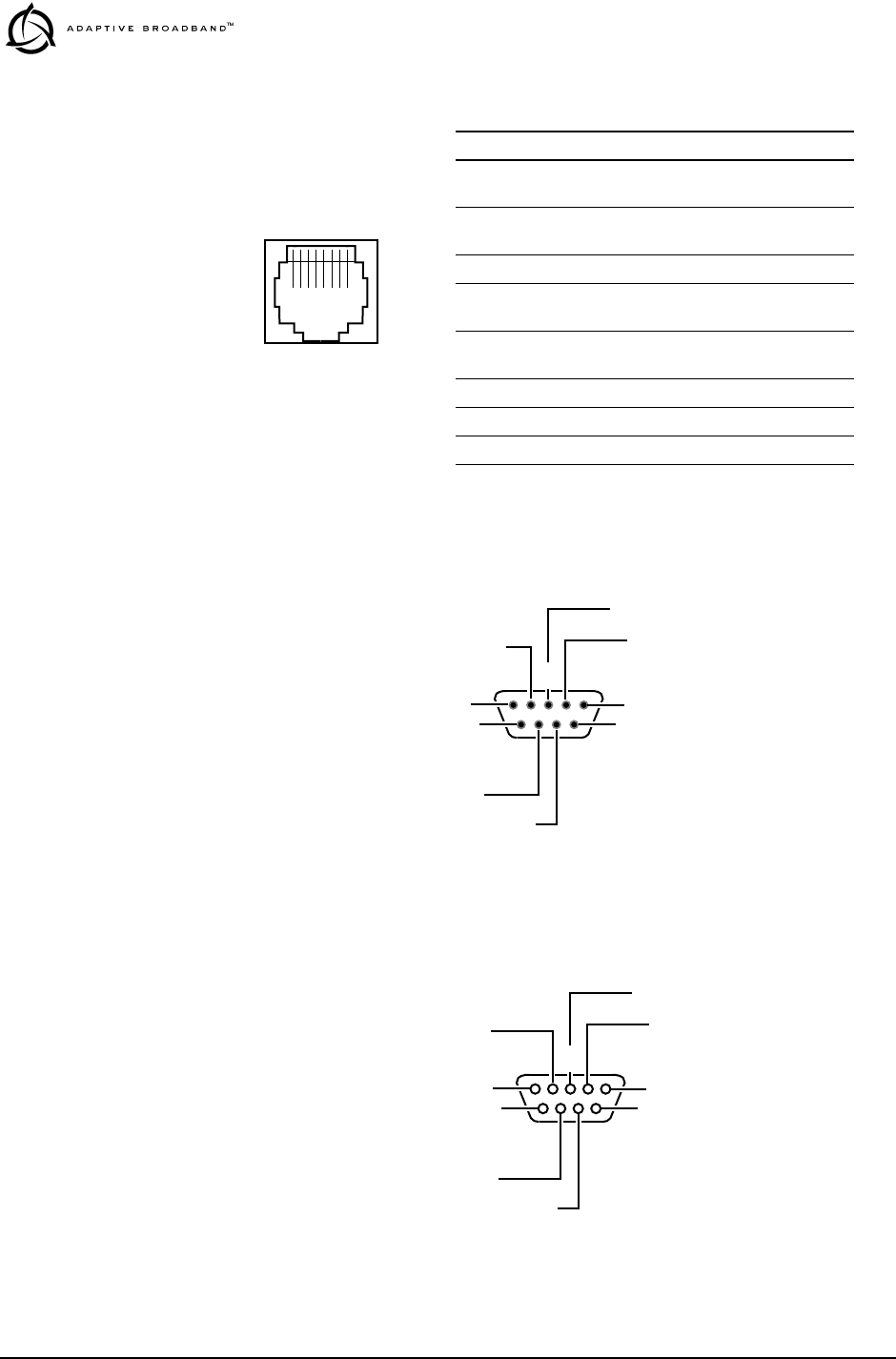
86 LEDR “S” Series I/O Guide MDS 05-3627A01, Rev. A
G.703 Data Connectors (4 on rear panel)
Invisible place holder
Figure 26. G.703 Data Connector Pinout
Service Channel Invisible place holder
Figure 27. Service Channel Connector DB-9 Male Pinout
Alarm Invisible place holder
Figure 28. Alarm Connector DB-9 Female Pinout
Pin Signal Direction
1 Differential digital
output signal, ring Output
2 Differential digital
output signal, tip Output
3 No Connection —
4 Differential digital
output signal, ring Input
5 Differential digital
output signal, tip Input
6 No Connection —
7 No Connection —
8 No Connection —
1 2 3 4 5 6 7 8
RJ-45
6
78
9
1
234
5DCD (IN)
RXD (DATA IN)
TXD (DATA OUT)
DTR (OUT)
DSR (IN)
RTS (OUT)
CTS (IN)
NC
GROUND
DTE
6
78
9
1
234
5ALARM IN 1
ALARM IN 2
ALARM IN 3
ALARM IN 4
ALARM OUT 1
ALARM OUT 2
ALARM OUT 3
ALARM OUT 4
GROUND

MDS 05-3627A01, Rev. A LEDR “S” Series I/O Guide 87
7.3 RF Propagation Planning
Establishing a reliable point-to-point radio link requires system plan-
ning and design. It is helpful to have an understanding of the physical
parameters affecting propagation. The following material discusses
these factors, and will assist you in designing a dependable transmission
path for your radio link.
NOTE: This section is intended for use as a guideline when planning
transmission paths. It does not consider all of the local condi-
tions that may be present, nor does it guarantee that adequate
signal strength will be obtained in a given system. There is no
substitute for an on-the-air test to verify the predicted path
results, and to check the overall operation of the radio system.
To ensure a highly reliable path, a line of sight between both ends of the
link is desirable. For short paths (up to 5 kilometers/3.1 miles), some
obstructions may be acceptable, but the performance of a blocked path
is always less predictable than a clear path.
Fresnel Zone Clearance
As the distance spanned by a link gets longer, it is necessary to have
more than just a grazing path between the two ends; the path must clear
the ground or other obstacles by some percentage of a Fresnel zone.
The Fresnel zone corresponds to the width or girth of the radio signal.
There are first, second, and third Fresnel zones, but the first zone is the
only one that has substantial effects on signal strength.
The first Fresnel zone can be visualized as an oval-shaped volume
between two station antennas (Figure 29). As the width of the radio
wave front gets blocked by obstructions, less of the signal can get to the
receiver antenna.
In addition to blocking the signal, obstructions in the first Fresnel zone
may also cause multipath interference due to reflective and refractive
signal paths. The reflected or refracted signal may arrive at the receiver
out of phase with the desired signal and cause a cancelling effect.
Invisible place holder
Figure 29. Fresnel Zone Obstructions
FRESNEL ZONE
STATION A STATION B
NOT
OBSTRUCTING
OBSTRUCTION
Distance D2
Distance D1
LINE-OF-SIGHT (LOS)

88 LEDR “S” Series I/O Guide MDS 05-3627A01, Rev. A
Experience has shown that 60 percent of the first Fresnel zone must be
clear of obstructions (0.6 x F) to allow a clear, unobstructed microwave
path.
Remember, the first Fresnel zone calculation is only one parameter
determining path quality.
Earth Curvature
As the distance of a communication link increases, the clearance
problem is compounded by the earth’s curvature. Radio waves traveling
through typical atmospheric conditions bend slightly, which is repre-
sented by treating the earth as though it were slightly flatter than it actu-
ally is. Experience has shown that if we consider the earth’s radius to be
4/3rds of its actual size, we get good agreement between theory and
measured propagation results.
Figure 30 shows a representation of the 4/3 earth “radio horizon.” This
figure shows that under normal radio propagation conditions, a station
with its antenna 15 meters above flat terrain will have a radio horizon
approximately 15 kilometers away, well beyond the visual horizon.
Invisible place holder
Figure 30. Antenna Height vs. Theoretical Radio Horizon
Fade Margins
Variations in the temperature and humidity of the atmosphere with ele-
vation cause the signals to bend more or less, resulting in fading at the
receiver. The longer the path is, the more likely that deep fades will
occur; hence, the greater the fade margin required.
Different parts of the world have differing propagation which can be cat-
egorized as favorable, average, or adverse. In general, mountainous
areas have favorable propagation conditions, while tropical areas and
those near large bodies of water have adverse conditions.
(0)
0(2) (4) (6) (8) (10) (12) (14) (16) (18) (20) (22) (24) (26) (28) (30) (32) (34)
(0)
0
(50)
15
(100)
30
(150)
46
(200)
61
(250)
76
(36)
Radio Horizon Over Level Terrain in Kilometers (Miles)
Normal Conditions
Antenna
Height in
Meters
(Feet)
585552484542393532 292623191610 1363

MDS 05-3627A01, Rev. A LEDR “S” Series I/O Guide 89
Based upon the desired level of link availability, path length, and terrain
type, it is possible to calculate the recommended fade margin.
The following standard formulas are provided for assistance in deter-
mining system installation parameters.
Free Space Path Loss
Where:
αfs = free space loss in dB
d = path distance in kilometers
ƒ = frequency in GHz
Parabolic Antenna Gain
Where:
G = antenna gain in dBi
D = dish diameter in meters
ƒ = frequency in GHz
This formula assumes a typical 50 percent antenna illumination effi-
ciency and is representative of a full parabolic antenna.
Fresnel Zone Boundary
Where:
Fn = Fresnel zone boundary in meters
d1 = distance from one end of the path to the Fresnel zone
boundary in kilometers)
d2 = distance from the other end of the path to the Fresnel zone
boundary (in kilometers)
D = total path distance (d1+d2) in kilometers
ƒ = frequency in GHz
n = Fresnel zone, 1 (for 1st) is used here
Parabolic Antenna Beamwidth
αfs 92.4 20 10 flog 20 10dlog++=
G20() 10 7.4Df()log=
Fnnd1d2
⋅()fD()⁄
17.3
=
φ21.3 fD()⁄=

90 LEDR “S” Series I/O Guide MDS 05-3627A01, Rev. A
Where:
φ = beamwidth in degrees (between –3 dB points)
ƒ = frequency in GHz
D = dish diameter in meters
This formula is representative of a full parabolic antenna.
Theoretical Signal Strength
Where:
RSSI = signal strength at the receiver in dBm
EIRP = RF Power Output in dBm + Gta –Ltfl
αfs = free-space path loss in dB
Gra = receive antenna gain in dBi
Lrfl = receive feedline loss in dB
Ltfl = transmit feedline loss in dB
Gta = transmit antenna gain in dBi
Probability of System Fading
Where:
FProb = probability of fading more than F
a = terrain factor
• 4 is used for very smooth terrain such as over water
• 1 is used for average terrain, with moderate roughness
• 0.25 is used for mountainous, or very rough terrain
b = climate factor
• 0.5 is used for a hot, humid climate
• 0.25 is used for temperate or northern areas
• 0.125 is used for a very dry climate
ƒ = frequency in GHz
d = path length in km
F = fade margin, in dB
7.4 Bench Testing of Radios
In some cases, it may be necessary to test the operation of the equipment
in a bench setting. Figure 31 shows a simple arrangement for bench
testing using RF attenuators between the two units under test.
RSSI EIRP α–fs Gra Lrfl
–+=
FProb a b 6.0 10 7– fd
310 F–()10⁄
××××××=
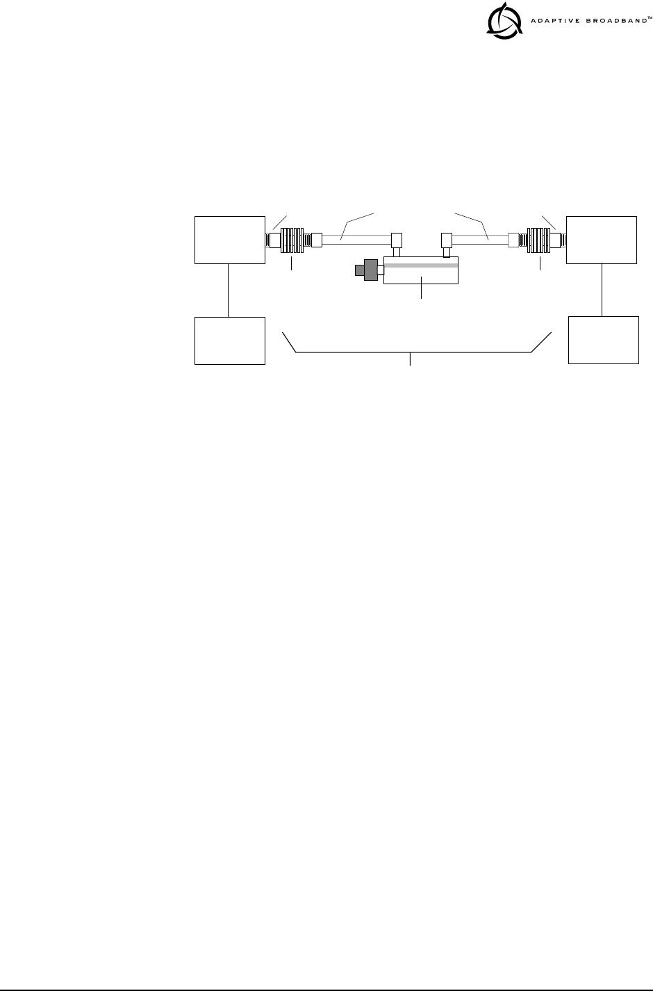
MDS 05-3627A01, Rev. A LEDR “S” Series I/O Guide 91
For weak signal tests (weaker than –80 dBm), additional physical sepa-
ration between radio #1 and radio #2 may be required to prevent unin-
tentional coupling between the radios.
On protected radio configurations, a weak received signal will cause the
transceivers to switch.
Invisible place holder
Figure 31. Back-to-Back Link Test
ANT
Connector ANT
Connector
POWER ATTENUATOR
• 30 dB
• 1W Rating
POWER ATTENUATOR
• 30 dB
• 1W Rating
SWITCHED OR VARIABLE
ATTENUATOR
• 0–110 dB (1 dB Steps)
JFW 50DR-001 or Equivalent
• Required only for receiver sensitivity test.
LOW LOSS COAXIAL LINES
DIGITAL
EQUIPMENT
OR BER
TESTER
RADIO
#1
DATA PORT
TOTAL ATTENUATION
Fixed: 80 dB Minimum for Basic Checks
Adjustable: For Sensitivity Tests (100–140 dB Required)
DIGITAL
EQUIPMENT
OR BER
TESTER
DATA PORT
RADIO
#2

92 LEDR “S” Series I/O Guide MDS 05-3627A01, Rev. A
7.5 Watts dBm Volts conversion
Table 19 is provided as a convenience for determining the equivalent
voltage or wattage of an RF power expressed in dBm.
Invisible place holder
Table 19. dBm-Volts-Watts Conversion Chart
dBm V Po
+53 100.0 200W
+50 70.7 100W
+49 64.0 80W
+48 58.0 64W
+47 50.0 50W
+46 44.5 40W
+45 40.0 32W
+44 32.5 25W
+43 32.0 20W
+42 28.0 16W
+41 26.2 12.5W
+40 22.5 10W
+39 20.0 8W
+38 18.0 6.4W
+37 16.0 5W
+36 14.1 4W
+35 12.5 3.2W
+34 11.5 2.5W
+33 10.0 2W
+32 9.0 1.6W
+31 8.0 1.25W
+30 7.10 1.0W
+29 6.40 800mW
+28 5.80 640mW
+27 5.00 500mW
+26 4.45 400mW
+25 4.00 320mW
+24 3.55 250mW
+23 3.20 200mW
+22 2.80 160mW
+21 2.52 125mW
+20 2.25 100mW
+19 2.00 80mW
+18 1.80 64mW
+17 1.60 50mW
+16 1.41 40mW
+15 1.25 32mW
+14 1.15 25mW
+13 1.00 20mW
+12 .90 16mW
+11 .80 12.5mW
+10 .71 10mW
+9 .64 8mW
+8 .58 6.4mW
+7 .500 5mW
+6 .445 4mW
+5 .400 3.2mW
+4 .355 2.5mW
+3 .320 2.0mW
+2 .280 1.6mW
+1 .252 1.25mW
dBm V Po
0 .225 1.0mW
-1 .200 .80mW
-2 .180 .64mW
-3 .160 .50mW
-4 .141 .40mW
-5 .125 .32mW
-6 .115 .25mW
-7 .100 .20mW
-8 .090 .16mW
-9 .080 .125mW
-10 .071 .10mW
-11 .064
-12 .058
-13 .050
-14 .045
-15 .040
-16 .0355
dBm mV Po
-17 31.5
-18 28.5
-19 25.1
-20 22.5 .01mW
-21 20.0
-22 17.9
-23 15.9
-24 14.1
-25 12.8
-26 11.5
-27 10.0
-28 8.9
-29 8.0
-30 7.1 .001mW
-31 6.25
-32 5.8
-33 5.0
-34 4.5
-35 4.0
-36 3.5
-37 3.2
-38 2.85
-39 2.5
-40 2.25 .1µW
-41 2.0
-42 1.8
-43 1.6
-44 1.4
-45 1.25
-46 1.18
-47 1.00
-48 0.90
dBm mV Po
-49 0.80
-50 0.71 .01µW
-51 0.64
-52 0.57
-53 0.50
-54 0.45
-55 0.40
-56 0.351
-57 0.32
-58 0.286
-59 0.251
-60 0.225 .001µW
-61 0.200
-62 0.180
-63 0.160
-64 0.141
dBm µV Po
-65 128
-66 115
-67 100
-68 90
-69 80
-70 71 .1nW
-71 65
-72 58
-73 50
-74 45
-75 40
-76 35
-77 32
-78 29
-79 25
-80 22.5 .01nW
-81 20.0
-82 18.0
-83 16.0
-84 11.1
-85 12.9
-86 11.5
-87 10.0
-88 9.0
-89 8.0
-90 7.1 .001nW
-91 6.1
-92 5.75
-93 5.0
-94 4.5
-95 4.0
-96 3.51
-97 3.2
dBm µV Po
-98 2.9
-99 2.51
-100 2.25 .1pW
-101 2.0
-102 1.8
-103 1.6
-104 1.41
-105 1.27
-106 1.18
dBm nV Po
-107 1000
-108 900
-109 800
-110 710 .01pW
-111 640
-112 580
-113 500
-114 450
-115 400
-116 355
-117 325
-118 285
-119 251
-120 225 .001pW
-121 200
-122 180
-123 160
-124 141
-125 128
-126 117
-127 100
-128 90
-129 80 .1ƒW
-130 71
-131 61
-132 58
-133 50
-134 45
-135 40
-136 35
-137 33
-138 29
-139 25
-140 23 .01ƒW

MDS 05-3627A01, Rev. A LEDR “S” Series I/O Guide 93
GLOSSARY
AMI—Alternate Mark Inversion. A bipolar
format where consecutive marks (ones) have
the polarity inverted. Spaces (ones) are repre-
sented by zero volts. This technique prevents
long sequences of positive or negative volt-
ages.
Analog—Signals with a continuously varying
amplitude, such as the human voice.
BERT—Bit-error rate test. The results of a
BERT are normally expressed as a ratio (power
of 10) of the number of bits received in error
compared to the total number received.
BER—Bit-error rate. See also BERT.
Bit—Binary digit. The smallest unit of digital
data, often represented by a one or a zero. Eight
bits usually comprise a byte.
bps—Bits-per-second. A measure of the infor-
mation transfer rate of digital data across a
communication channel.
Byte—A digital “word” usually made up of
eight bits.
dBi—Decibels of gain relative to an isotropic
radiator. (A hypothetical antenna which radi-
ates equally in all directions.) Used to express
antenna gain.
dBm—Decibels relative to one milliwatt. An
absolute unit used to measure signal power, as
in transmitter power output, or received signal
strength.
DTR—Data Terminal Ready. A control signal
sent from the radio indicating that it is ready to
transmit data.
CPE—Customer premise (provided) equip-
ment.
DCE— Data (circuit terminating) Communi-
cations Equipment. In data communications
terminology, this is the “modem” side of a
computer-to-modem connection. The trans-
ceiver is a DCE device which is designed to
connect to a DTE device.
Decibel (dB)—A measure of the ratio between
two signal levels. Frequently used to express
the gain or loss of a system.
DSP—Digital Signal Processing. A processing
technique that uses software algorithms to
filter, shape, or otherwise modify the character-
istics of a given signal. In the LEDR radio, DSP
is used primarily in modulation and demodula-
tion functions.
E1—An international telephony standard that
operates at 2.048 megabits-per-second (Mbps).
This transmission speed is commonly used
throughout the world except for North America
(which uses T1 1.544 Mbps). Framed E1 con-
sists of 30 digitized telephone channels and two
64 Kbps control channels.
EIRP—Effective Isotropic Radiated Power.
Commonly used to express the power radiated
from a gain antenna. It is equal to the power
transmitted (minus feedline loss) plus the
antenna gain.
ESF—Extended Super Frame.
Fade Margin—The maximum tolerable reduc-
tion in received signal strength which still pro-
vides an acceptable signal quality. This
compensates for reduced signal strength due to
multipath, slight antenna movement or
changing atmospheric losses. Expressed in
decibels.

94 LEDR “S” Series I/O Guide MDS 05-3627A01, Rev. A
FEC—Forward Error Correction. Extra data is
added to the transmitted signal to allow for
detection and correction of some transmission
errors.
Frame—A segment of data that adheres to a
specific data protocol and contains definite
start and end points. It provides a method of
synchronizing transmissions.
Fresnel Zone—A point of maximum width or
girth of the transmitted radio signal. Obstruc-
tions in this region (the “first Fresnel zone”)
can have a detrimental effect on reception
quality. As a general rule, 60 percent of the first
Fresnel zone should be free of obstructions in a
well designed system. (Additional consider-
ations are also required when planning a micro-
wave path.
G.703—The ITU standard defining the charac-
teristics of digital interfaces (pulse shape,
voltage levels, etc.). This applies to high-speed,
three-level data being sent over coaxial or
twisted pair lines.
G.821—The ITU standard by which data trans-
mission quality is measured. The analysis con-
siders available vs. unavailable time.
Half-Power Beamwidth—The customary
way of measuring the width of a directional
antenna’s radiation pattern. This beamwidth is
measured in degrees between the half-power
points (the point at which the power is reduced
3 dB with respect to the main beam).
HDB3—High density bipolar order of 3. A line
interface standard for E1 transmission that
employs coding to eliminate data streams with
four or more consecutive zeros.
IP—Internet Protocol.
ITU—International Telecommunications
Union.
kbps—Kilobits-per-second.
Linecode—Refers to the data coding format
used by the radio for the line interface. (It does
not pertain to the radio’s modulation coding.)
The available linecode selections are HDB3
and AMI.
Mbps—Megabits-per-second.
MIB—Management Information Base. The
MIB stores SNMP messages that are directed to
the management console. This can include
Server events, statistical data and system que-
ries.
Multipath Fading—Signals arriving at the
receiver out of phase which have a tendency to
cancel each other. It is caused by reflections of
the transmitted wave and results in distortion at
the receiver or weak received signal strength.
Multiplexer—A signal processing unit that
combines multiple streams of data into one for
transmission across a single data channel.
NMS—Network Management System. A soft-
ware application used to configure, diagnose
and monitor a communication network. The
LEDR radio’s SNMP program is an example of
an NMS.
Protected Radio—A radio configuration
where there are redundant modules that auto-
matically become active in the event of a
failure.
QAM—Quadrature Amplitude Modulation.
Uses phase shifts and amplitude changes to
send high-speed data in a comparatively
narrow RF channel. See also QPSK.
QPSK—Quadrature Phase Shift Keying. Uses
four levels of phase shift to send high-speed
data with a higher system gain than QAM mod-
ulation. See also QAM.
RSSI—Received signal strength indication.
Expressed in dBm.

MDS 05-3627A01, Rev. A LEDR “S” Series I/O Guide 95
SNMP—Simple Network Management Pro-
tocol. A common network management system
(NMS) protocol used to monitor and control a
communications network
SNR—Signal-to-noise ratio. Expressed in
decibels (dB).
SWR—Standing Wave Ratio. A parameter
related to the ratio between forward transmitter
power and the reflected power from the antenna
system. As a general guideline, reflected power
should not exceed 10% of the forward power
(≈2:1 SWR).
T1—A telephony standard that operates at
1.544 megabits-per-second (Mbps). This trans-
mission speed is commonly used in North
America.
TFTP—Trivial File Transfer Protocol. A stan-
dard network protocol used to send and receive
files between two devices.


IN CASE OF DIFFICULTY...
Adaptive Broadband Corporation/MDS products are designed for long life and trouble-free oper-
ation. However, this equipment, as with all electronic equipment, may have an occasional compo-
nent failure. The following information will assist you in the event that servicing becomes
necessary.
FACTORY TECHNICAL ASSISTANCE
Technical assistance for Adaptive Broadband/MDS products is available from our Customer
Support Team during business hours (8:00 A.M.–5:30 P.M. Eastern Time). When calling, please
give the complete model number of the radio, along with a description of the trouble symptom(s)
that you are experiencing. In many cases, problems can be resolved over the telephone, without
the need for returning the unit to the factory.
Please use the following telephone numbers for product assistance:
716-242-9600 (Phone)
716-242-9620 (FAX)
FACTORY REPAIRS
Component level repair of radio equipment is not recommended in the field. Many components
are installed using surface mount technology, which requires specialized training and equipment
for proper servicing. For this reason, the equipment should be returned to the factory for any PC
board repairs. The factory is best equipped to diagnose, repair and align your radio to its proper
operating specifications.
If return of the equipment is necessary, you will be issued a Returned Material Authorization
(RMA) number. The RMA number will help expedite the repair so that the equipment can be
repaired and returned to you as quickly as possible. Please be sure to include the RMA number
on the outside of the shipping box, and on any correspondence relating to the repair. No equipment
will be accepted for repair without an RMA number.
A statement should accompany the radio describing, in detail, the trouble symptom(s), and a
description of any associated equipment normally connected to the radio. It is also important to
include the name and telephone number of a person in your organization who can be contacted if
additional information is required.
The radio must be properly packed for return to the factory. The original shipping container and
packaging materials should be used whenever possible. All factory returns should be addressed to:
When repairs have been completed, the equipment will be returned to you by the same shipping
method used to send it to the factory. Please specify if you wish to make different shipping
arrangements.
Adaptive Broadband Corp.
MDS Products Group
Customer Service Department
(RMA No. XXXX)
175 Science Parkway
Rochester, NY 14620 USA

MDS Products Group
175 Science Parkway, Rochester, New York 14620
General Business: +1 (716) 242-9600
FAX: +1 (716) 242-9620
www.microwavedata.com