GS Instech COVERCELL25K In-Building RF Repeater User Manual
GS Instruments Co., Ltd. In-Building RF Repeater Users Manual
UserManual.wiki
>
GS Instech
>
COVERCELL25K User Manual
Users Manual
Navigation menu
Upload a User Manual
Namespaces
Wiki Guide
HTML
PDF
Info
Views
User Manual
Discussion / Help
Navigation
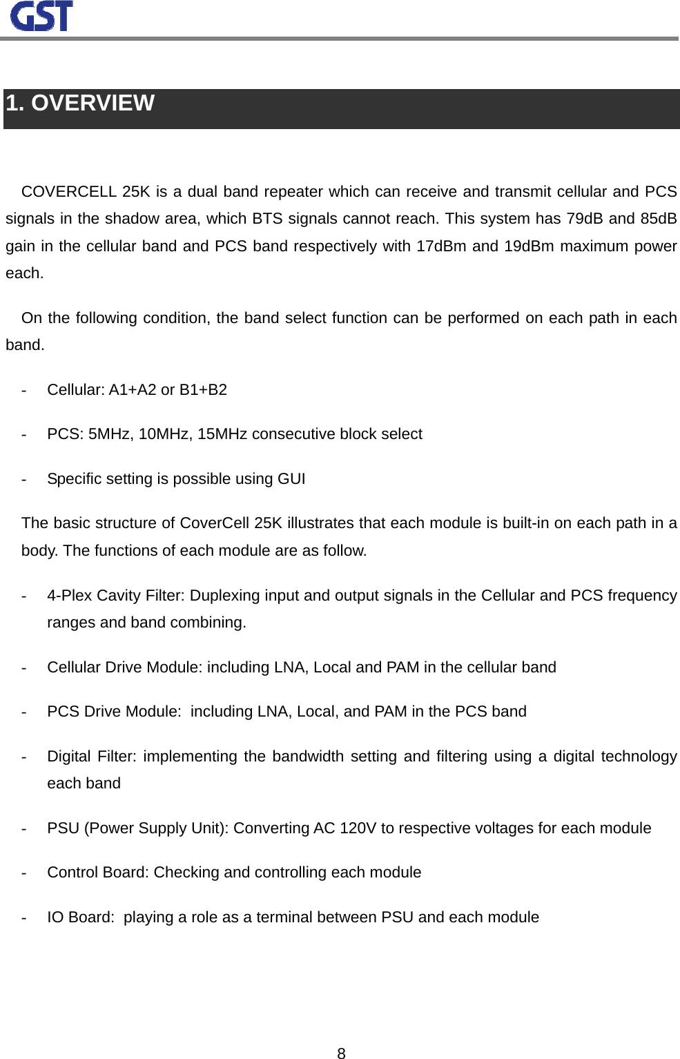
![10[Figure 1] COVERCELL 25K RF Repeater Operating Example 2.2 SYSTEM DESIGN AND OPERATIONS 2.2.1 SYSTEM DESIGN NO PART FUNCTIONS 1 Donor 4-Plex Cavity Filter Downlink Input, Uplink Output, path separated 2 Coverage 4-Plex Cavity Filter Downlink Output, Uplink Input, path separated 3 Cellular Drive Module LNA/ PAM, Service Band Select RCU (Upper) Repeater Control and High-level CommunicationPCS Drive Module (Middle) LNA / PAM , Service Band Select 4 Digital Filter (Lower) Deciding Bandwidth in the Selected Band 5 7.5V Power Supply Unit Drive Module Power Supply](https://usermanual.wiki/GS-Instech/COVERCELL25K/User-Guide-1032750-Page-11.png)
![116 5V Power Supply Unit Digital Filter Power Supply 7 IO Board Terminal board for controlling a repeater 8 PCS Wave Detector PCS Service Band noise detect 9 Cellular Wave Detector Cellular Service Band noise detect 10 PCS Coupling PCS RX Service Signal Extract 11 Cellular Coupling Cellular RX Service Signal Extract 12 Cellular DL_BPF Blocking IF external signals 13 Cellular UL_BPF Blocking IF external signals 14 PCS_DL_BPF Blocking IF external signals 15 PCS_UL_BPF Blocking IF external signals [Figure 2] COVERCELL 25K RF Repeater Internal Structure [Figure 3] COVERCELL 25K RF Repeater Port NO PORT FUNCTIONS 1 Debug Port GUI Connecting port, 9pin D-sub 2 AC Power port AC 120V 60Hz 3 LAN1 High-level Communication port 4 LAN2 High-level Communication port 5 Coverage ANT Antenna for terminals 6 Donor ANT Antenna for BTS](https://usermanual.wiki/GS-Instech/COVERCELL25K/User-Guide-1032750-Page-12.png)

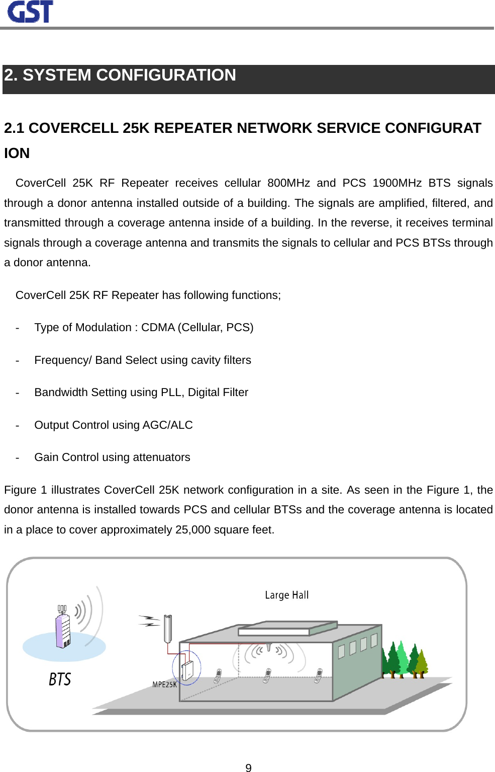
![132.2.2 Downlink Block Diagram CoverCell 25K is a dual band repeater that can handle cellular and PCS signals. Basically RF modules are separated from each path and band. One module can handle all the functions except 4 plexer and digital filter. Also one integrated chip which includes local and mixer consists a block and input detect process is performed to prevent external signals from affecting other signals after signals are through a digital filter. [Figure 4] COVERCELL 25K RF Repeater Downlink Block Diagram COVERCELL 25K RF Repeater Downlink Block Diagram Cellular Donor Coverage Digital FilterMixer + Local Input Det Output DetOutput Det LNA LNA PCS Cavity Filter Cavity Filter PAM PAM Digital FilterMixer + LocalInput Det](https://usermanual.wiki/GS-Instech/COVERCELL25K/User-Guide-1032750-Page-14.png)
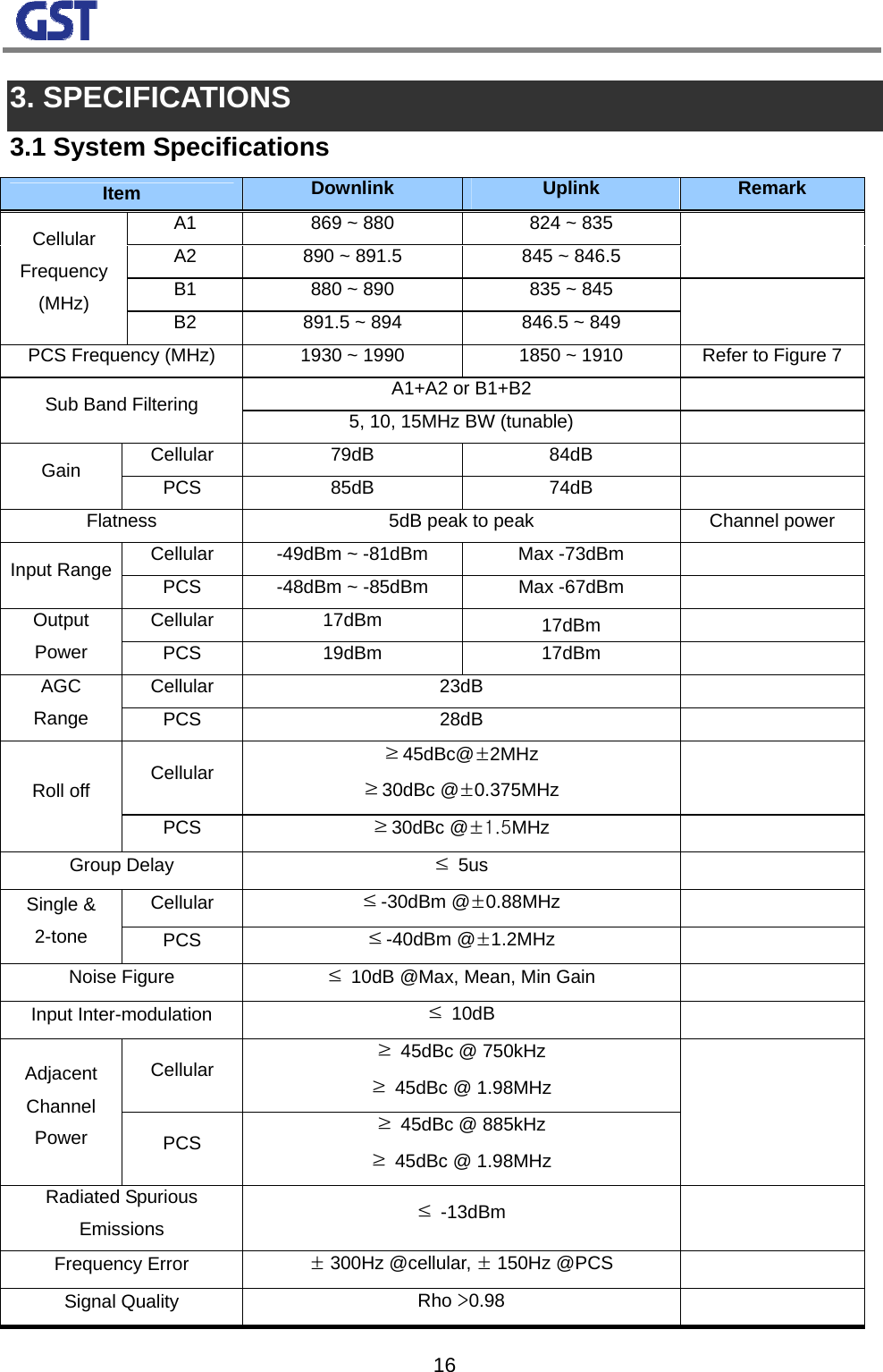
![142.2.3 Uplink Block Diagram The uplink path of CoverCell 25K does not use the input detect function. The gain of a donor antenna is high enough. Then, the last output power level is not necessarily high. Consequently, PAM is not necessary. The ALC function is monitoring the last output power and maintaining the output power to increase stability of the system. [Figure 5] COVERCELL 25K RF Repeater Uplink Block Diagram COVERCELL 25K RF Repeater Uplink Block Diagram CellularDonor ANT Digital FilterMixer + Local Output Det Output Det LNA LNA PCSCavity Filter Cavity Filter Digital FilterMixer + LocalCoverage ANT](https://usermanual.wiki/GS-Instech/COVERCELL25K/User-Guide-1032750-Page-15.png)
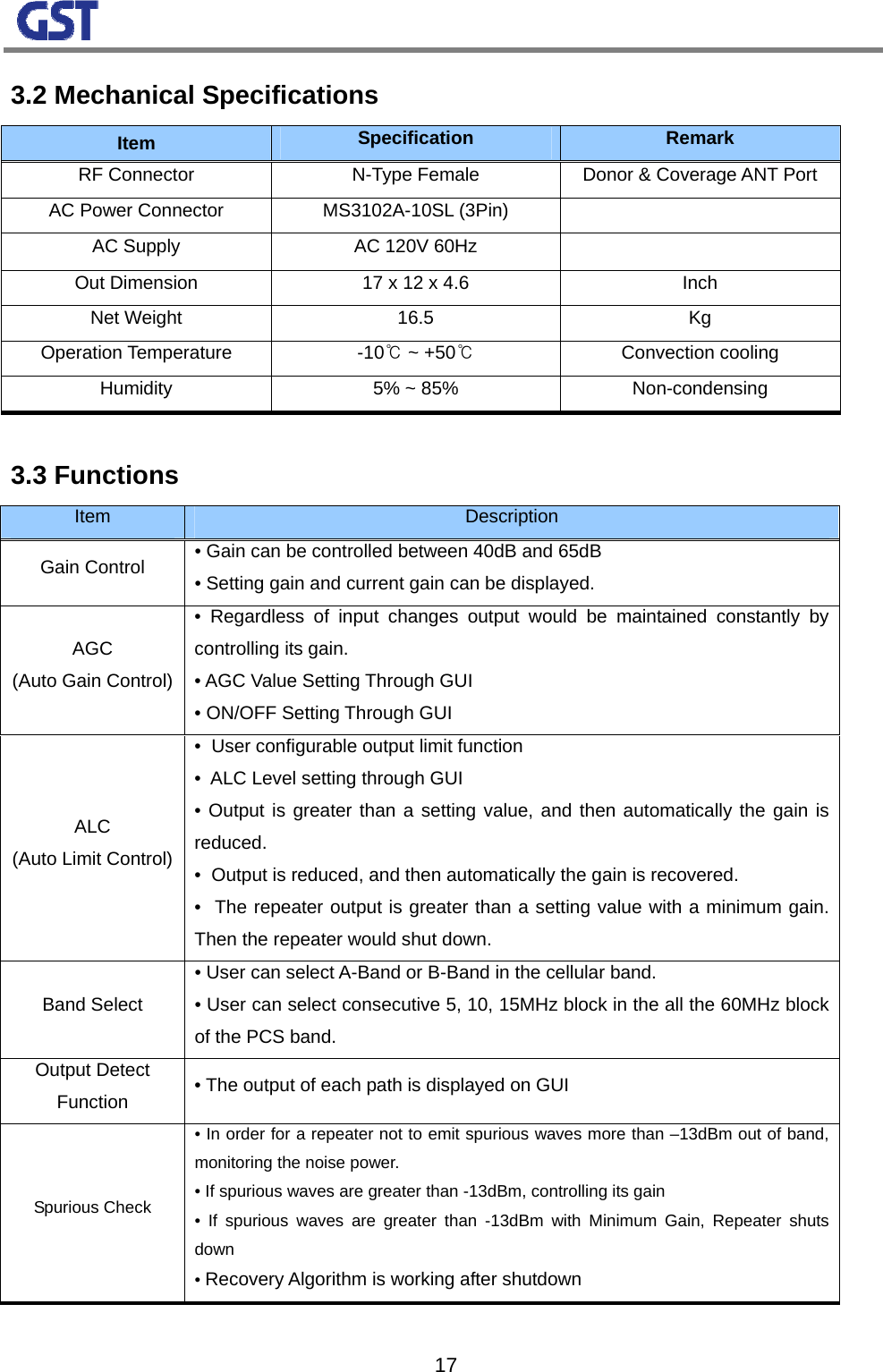
![152.2.5 Frequency Selection [Figure 7] PCS Band Structure Based on the band select function, 5MHz, 10MHz, and 15MHz bands can be selected on the following condition. - Any 5MHz bands can be chosen in the all the blocks. - 10MHz or 15MHz band can be selected in any combinations In the consecutive bands - C1, C2 select is not supported. A1 A2 A3 D B1 B2 B3 E F C3 C4 C51930MHz 1990MHzA1 A2 A3 D B1 B2 B3 E F C3 C4 C51850MHz 1910MHz< Downlink >< Uplink >](https://usermanual.wiki/GS-Instech/COVERCELL25K/User-Guide-1032750-Page-16.png)
![194. INSTALLATION 4.1 SYSTEM INSTALLATION 4.1.1 Contents of Box (1 SET) Category Contents Quantity Repeater COVERCELL 25K Repeater 1 EA Accessory Power Cable Mounting Bracket Screws 1 EA 1 EA 1 SET USER MANUAL MANUAL 1 EA 4.1.2 Caution 1) System Main Power Check: the main input power of this repeater is AC110V A : 110V ~ 125VAC B : 110V ~ 125VAC C : GND [Figure 8] MS 3100 A 10SL-3 (Wall Mount Receptacle) & MS3010 A 10SL-3(Plug) 2) Input Condition Optimization: A. Cellular Forward Input Condition: -81 ~ -49dBm B. PCS Forward Input Condition: -85 ~ -48dBm C. Adjusting system input condition to be optimized after comparing a donor antenna input condition to A and B 3) Measuring Isolation between Donor/Coverage Antennas A. Cellular: ≥96dBc(Gain +15dB) B. PCS: ≥100dBc (Gain+15dB) C. Checking the above conditions, adjusting system input condition to be optimized. 4) The standard installation of this repeater is vertically wall-typed.](https://usermanual.wiki/GS-Instech/COVERCELL25K/User-Guide-1032750-Page-20.png)
![20 [Figure 9] Dual-band In-building Repeater 434300GS Teletech Inc. Tech Support 1-866-9-GST-USA (toll free) [Figure 10] Dual-band In-building Repeater](https://usermanual.wiki/GS-Instech/COVERCELL25K/User-Guide-1032750-Page-21.png)
![214.1.3 System Initiation 1) Check points after connecting networks A. External LED RUN: ①When Power On, green light blinks. Otherwise, the lamp is off. ALARM: ②When alarming situations happen, the yellow light is on. Otherwise, it is off. SHUT DOWN: When Shut Down③ situations occur, the yellow light is on. Otherwise, it is off. [Figure 11] dual-band In-building Repeater Repeater Front LED B. Checking through Debug Program C. Checking output power Checking output status through output monitoring port and the characteristics of unnecessary waveforms using a spectrum analyzer D. Checking service quality status in the service area Checking service signal quality status using terminals in the service area 4.2 TROUBLESHOOTING When the repeater is abnormal, diagnosing with remote control or site debug functions. If major alarms go off, turn it off and contact customer service at GS Teletech. a. Troubleshooting should be performed by trained technicians. b. No internal or external parts should be disassembled or tampered with for any reason. c. While troubleshooting, technician should use attenuator to check RF Signal output.](https://usermanual.wiki/GS-Instech/COVERCELL25K/User-Guide-1032750-Page-22.png)