GS Instech COVERCELL25K In-Building RF Repeater User Manual
GS Instruments Co., Ltd. In-Building RF Repeater Users Manual
Users Manual

FCC ID : U88-COVERCELL25K
HCT CO., LTD.
SAN 136-1, AMI-RI, BUBAL-EUP, ICHEON-SI, KYOUNGKI-DO, 467-701, KOREA
TEL:+82 31 639 8517 FAX:+82 31 639 8525 www.hct.co.kr
Report No. : HCT-R08-205 1/1
ATTACHMENT E.
- USER MANUAL -

GSTeletech
CoverCell 25K Repeater
USERS MANUAL
November 1, 2008
Version 1.1

2
WARNINGS, CAUTIONS, AND GENERAL NOTES
This product conforms to FCC Part 15, Section 21 of the FCC (Federal
Communications Commission) rules. Changes or modifications not expressly approved by the
party responsible for compliance could void the user’s authority to operate the equipment.
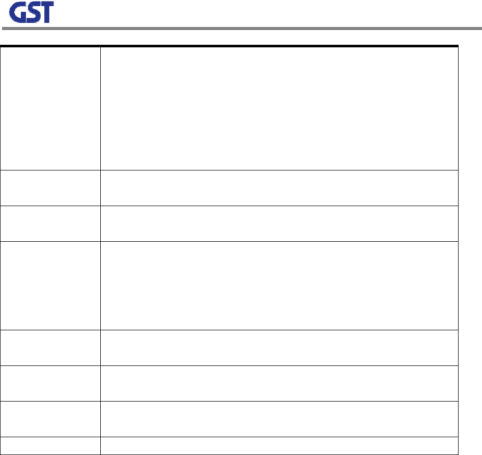
Indicates a procedure or practice, which, if ignored, may result in damage to the system or a
system component. Do not perform any procedure preceded by a WARNING until you
thoroughly understand the described conditions (e.g., To reduce the risk of burn, allow hot
devices to cool before handling).
Convention Definition
Warning
This equipment has been tested and found to comply with the limits for a Class A digital device,
pursuant to part 15 of the FCC rules. These limits are designed to provide reasonable protection
against harmful interference when the equipment is operating in a commercial environment.
This equipment generates, uses, and radiates radio frequency energy and, if not installed and
used in accordance with this operator’s manual, may cause harmful interference to radio
communications. Operation of this equipment in a residential area is likely to cause harmful
interference, in which case the user will be required to correct the interference at their expense.
Safety Considerations
When installing or using this product, observe all safety precautions during handling and
operation. Failure to comply with the following general safety precautions and with
specific precautions described elsewhere in this manual violates the safety standards of
the design, manufacture, and intended use of this product. GSTeletech assumes no
liability for the customer's failure to comply with these precautions.
WARNING
WARNING calls attention to a procedure or practice, which if ignored, may result in
damage to the system or system component. Do not perform any procedure preceded by
a WARNING until described conditions are fully understood and met.
If You Need Help
If you need additional copies of this manual, or have questions about system options, or need help

3
with installation and using of the system, please contact GSTeletech’ Customer Support.
GSTeletech Inc. Customer Support
6900 College Boulevard, Suite 850
Overland Park, KS 66211, USA
Toll Free: 1-866-9 GST USA
Phone: 913 469 6699
bdelozier@gsteletechinc.com
Service
Do not attempt to modify or service any part of this product other than in accordance with
procedures outlined in this Operator's Manual. If the product does not meet its warranted
specifications, or if a problem is encountered that requires service, notify GSTeletech
customer support department. Service will be rendered according the GSTeletech
warranty and repair policy. The product shall not be returned without contacting
GSTeletech and obtaining a return authorization number from the Customer Support
department.
When returning a product for service, include the following information: Owner, Model
Number, Serial Number, Return Authorization Number (obtained in advance from
GSTeletech Customer Support Department), service required and/or a description of the
problem encountered.
The GSTeletech Quality Plan includes product test and inspection operations to verify the
quality and reliability of our products.
GSTeletech uses every reasonable precaution to ensure that every device meets
published electrical, optical, and mechanical specifications prior to shipment. Customers
are asked to advise their incoming inspection, assembly, and test personnel as to the
precautions required in handling and testing ESD sensitive components. Physical damage
to the external surfaces voids warranty.
These products are covered by the following warranties:

4
1. General Warranty
GSTeletech warrants to the original purchaser all standard products sold by
GSTeletech to be free of defects in material and workmanship for the duration of
the warranty period of one (1) year from date of shipment from GSTeletech.
During the warranty period, GSTeletech obligation, at our option, is limited to repair
or replacement of any product that GSTeletech proves to be defective. This
warranty does not apply to any product, which has been subject to alteration,
abuse, improper installation or application, accident, electrical or environmental
over-stress, negligence in use, storage, transportation or handling.
2. Specific Product Warranty Instructions
All GSTeletech products are manufactured to high quality standards and are
warranted against defects in workmanship, materials and construction, and to no
further extent. Any claim for repair or replacement of a device found to be
defective on incoming inspection by a customer must be made within 30 days of
receipt of the shipment, or within 30 days of discovery of a defect within the
warranty period.
This warranty is the only warranty made by GSTeletech and is in lieu of all other
warranties, expressed or implied, except as to title, and can be amended only by a
written instrument signed by an officer of GSTeletech. GSTeletech sales agents or
representatives are not authorized to make commitments on warranty returns.
In the event that it is necessary to return any product against the above
warranty, the following procedure shall be followed:
a. Return authorization shall be received from the GSTeletech Customer
Support prior to returning any device. Advise the GSTeletech Customer
Support of the model, serial number, and the discrepancy. The device shall
then be forwarded to GSTeletech, transportation prepaid. Devices returned
freight collect or without authorization may not be accepted.

5
b. Prior to repair, GSTeletech Customer Support will advise the customer of
GSTeletech test results and will advise the customer of any charges for
repair (usually for customer caused problems or out-of-warranty conditions).
If returned devices meet full specifications and do not require repair, or if
non-warranty repairs are not authorized by the customer, the device may
be subject to a standard evaluation charge. Customer approval for the
repair and any associated costs will be the authority to begin the repair at
GSTeletech. Customer approval is also necessary for any removal of
certain parts, such as connectors, which may be necessary for GSTeletech
testing or repair.
c. Repaired products are warranted for the balance of the original warranty
period, or at least 90 days from date of shipment.
3. Limitations of Liabilities
GSTeletech liability on any claim of any kind, including negligence, for any loss or
damage arising from, connected with, or resulting from the purchase order,
contract, or quotation, or from the performance or breach thereof, or from the
design, manufacture, sale, delivery, installation, inspection, operation or use of any
equipment covered by or furnished under this contract, shall in no case exceed the
purchase price of the device which gives rise to the claim.
EXCEPT AS EXPRESSLY PROVIDED HEREIN, GSTELETECH MAKES NO
WARRANTY OF ANY KIND, EXPRESSED OR IMPLIED, WITH RESPECT TO
ANY GOODS, PARTS AND SERVICES PROVIDED IN CONNECTION WITH
THIS AGREEMENT INCLUDING, BUT NOT LIMITED TO, THE IMPLIED
WARRANTIES OF MERCHANTABILITY AND FITNESS FOR A PARTICULAR
PURPOSE. GSTELETECH SHALL NOT BE LIABLE FOR ANY OTHER
DAMAGE INCLUDING, BUT NOT LIMITED TO, INDIRECT, SPECIAL OR
CONSEQUENTIAL DAMAGES ARISING OUT OF OR IN CONNECTION WITH
FURNISHING OF GOODS, PARTS AND SERVICE HEREUNDER, OR THE
PERFORMANCE, USE OF, OR INABILITY TO USE THE GOODS, PARTS AND
SERVICE.

6
GSTeletech test reports or data indicating mean-time-to-failure, mean-time-
between-failure, or other reliability data are design guides and are not intended to
imply that individual products or samples of products will achieve the same results.
These numbers are to be used as management and engineering tools, and are not
necessarily indicative of expected field operation. These numbers assume a
mature design, good parts, and no degradation of reliability due to manufacturing
procedures and processes.
Handling the GST Repeater
1. Use ESD precautions when dealing with the modules within the repeater so that units are not
damaged.
2. Opening the unit voids warranty.
3. Disconnecting any component within the repeater when powered can damage or destroy the
equipment and will void the warranty.

7
- Table of Contents -
1. OVERVIEW ................................................................................................................ 8
2. SYSTEM CONFIGURATION...................................................................................... 9
2.1 COVERCELL 25K REPEATER NETWORK SERVICE CONFIGURATION................9
2.2 SYSTEM DESIGN AND OPERATIONS ................................................................. 10
2.2.1 SYSTEM DESIGN ............................................................................................... 10
3. SPECIFICATIONS.................................................................................................... 16
3.1 System Specifications......................................................................................................16
3.2 Mechanical Specifications...............................................................................................17
3.3 Functions .............................................................................................................................17
4. INSTALLATION........................................................................................................ 19
4.1 SYSTEM INSTALLATION..................................................................................................19
4.2 TROUBLESHOOTING........................................................................................................21

8
1. OVERVIEW
COVERCELL 25K is a dual band repeater which can receive and transmit cellular and PCS
signals in the shadow area, which BTS signals cannot reach. This system has 79dB and 85dB
gain in the cellular band and PCS band respectively with 17dBm and 19dBm maximum power
each.
On the following condition, the band select function can be performed on each path in each
band.
- Cellular: A1+A2 or B1+B2
- PCS: 5MHz, 10MHz, 15MHz consecutive block select
- Specific setting is possible using GUI
The basic structure of CoverCell 25K illustrates that each module is built-in on each path in a
body. The functions of each module are as follow.
- 4-Plex Cavity Filter: Duplexing input and output signals in the Cellular and PCS frequency
ranges and band combining.
- Cellular Drive Module: including LNA, Local and PAM in the cellular band
- PCS Drive Module: including LNA, Local, and PAM in the PCS band
- Digital Filter: implementing the bandwidth setting and filtering using a digital technology
each band
- PSU (Power Supply Unit): Converting AC 120V to respective voltages for each module
- Control Board: Checking and controlling each module
- IO Board: playing a role as a terminal between PSU and each module
9
2. SYSTEM CONFIGURATION
2.1 COVERCELL 25K REPEATER NETWORK SERVICE CONFIGURAT
ION
CoverCell 25K RF Repeater receives cellular 800MHz and PCS 1900MHz BTS signals
through a donor antenna installed outside of a building. The signals are amplified, filtered, and
transmitted through a coverage antenna inside of a building. In the reverse, it receives terminal
signals through a coverage antenna and transmits the signals to cellular and PCS BTSs through
a donor antenna.
CoverCell 25K RF Repeater has following functions;
- Type of Modulation : CDMA (Cellular, PCS)
- Frequency/ Band Select using cavity filters
- Bandwidth Setting using PLL, Digital Filter
- Output Control using AGC/ALC
- Gain Control using attenuators
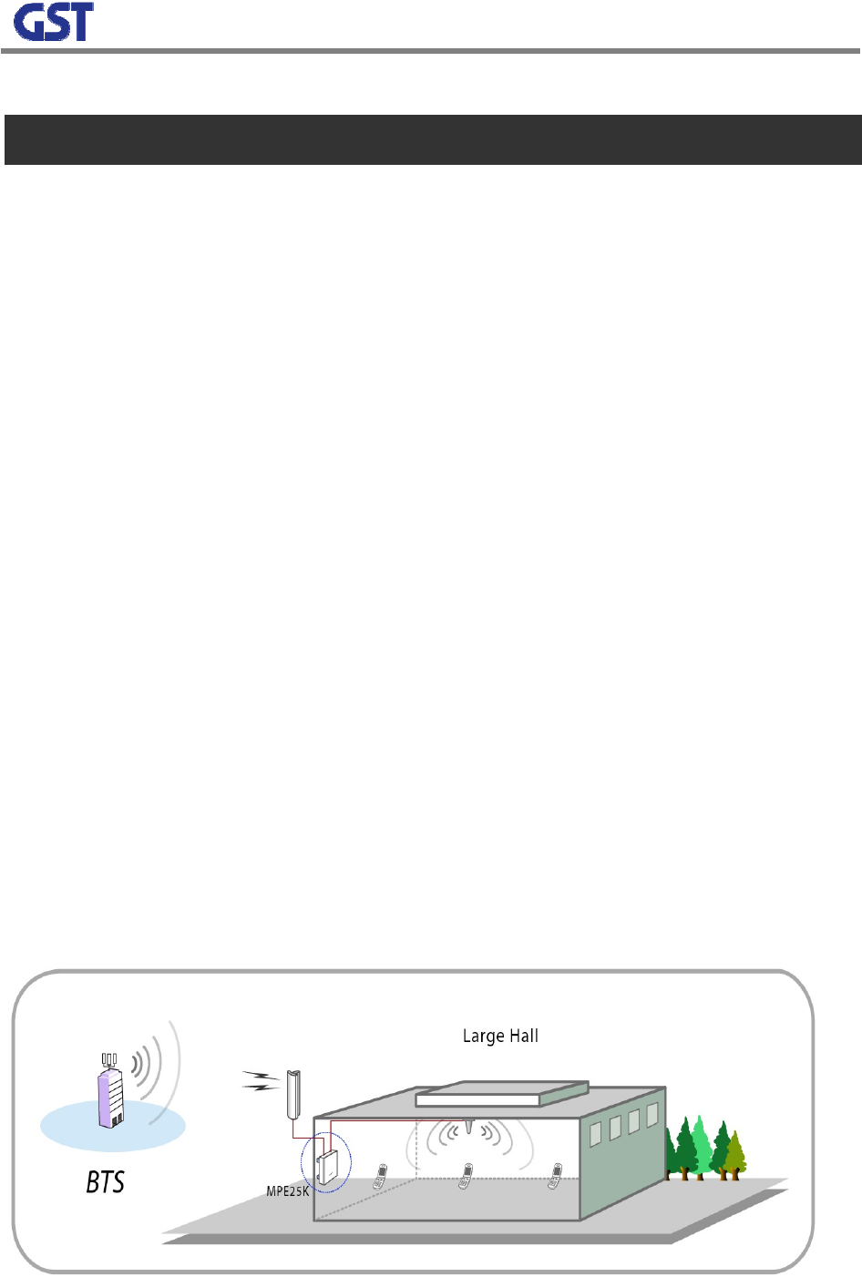
Figure 1 illustrates CoverCell 25K network configuration in a site. As seen in the Figure 1, the
donor antenna is installed towards PCS and cellular BTSs and the coverage antenna is located
in a place to cover approximately 25,000 square feet.
10
[Figure 1] COVERCELL 25K RF Repeater Operating Example
2.2 SYSTEM DESIGN AND OPERATIONS
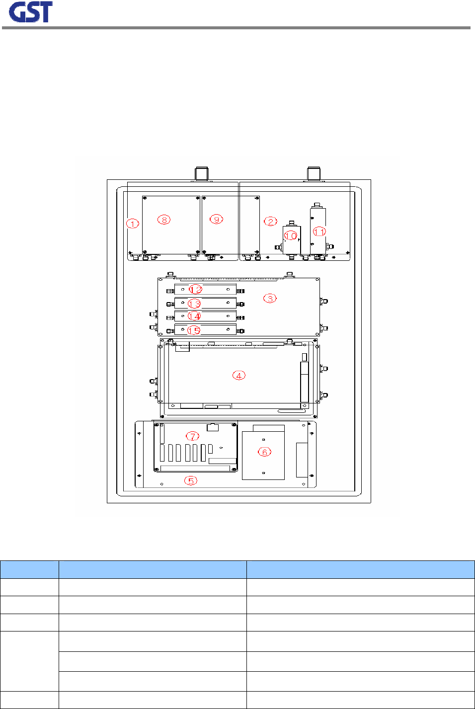
2.2.1 SYSTEM DESIGN
NO PART FUNCTIONS
1 Donor 4-Plex Cavity Filter Downlink Input, Uplink Output, path separated
2 Coverage 4-Plex Cavity Filter Downlink Output, Uplink Input, path separated
3 Cellular Drive Module LNA/ PAM, Service Band Select
RCU (Upper) Repeater Control and High-level Communication
PCS Drive Module (Middle) LNA / PAM , Service Band Select
4
Digital Filter (Lower) Deciding Bandwidth in the Selected Band
5 7.5V Power Supply Unit Drive Module Power Supply
11
6 5V Power Supply Unit Digital Filter Power Supply
7 IO Board Terminal board for controlling a repeater
8 PCS Wave Detector PCS Service Band noise detect
9 Cellular Wave Detector Cellular Service Band noise detect
10 PCS Coupling PCS RX Service Signal Extract
11 Cellular Coupling Cellular RX Service Signal Extract
12 Cellular DL_BPF Blocking IF external signals
13 Cellular UL_BPF Blocking IF external signals
14 PCS_DL_BPF Blocking IF external signals
15 PCS_UL_BPF Blocking IF external signals
[Figure 2] COVERCELL 25K RF Repeater Internal Structure
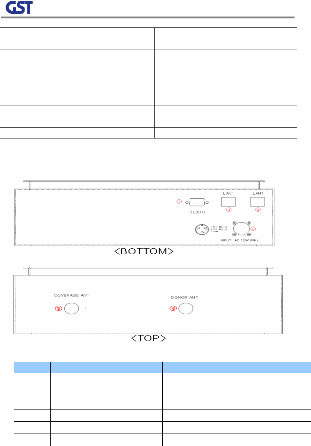
[Figure 3] COVERCELL 25K RF Repeater Port
NO PORT FUNCTIONS
1 Debug Port GUI Connecting port, 9pin D-sub
2 AC Power port AC 120V 60Hz
3 LAN1 High-level Communication port
4 LAN2 High-level Communication port
5 Coverage ANT Antenna for terminals
6 Donor ANT Antenna for BTS

12
13
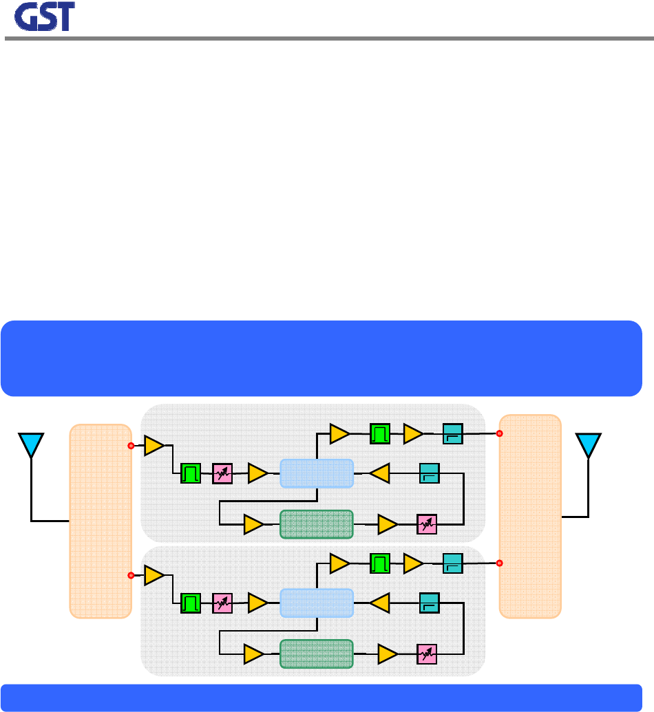
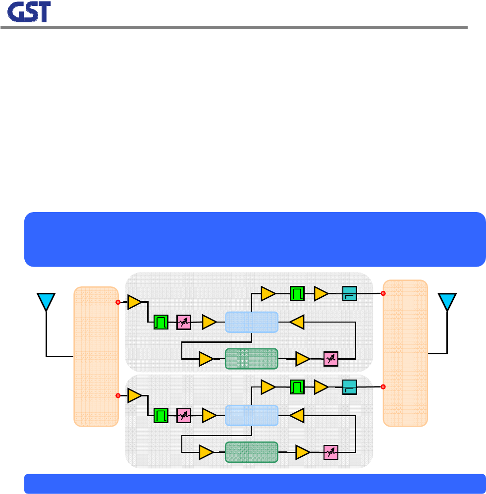
2.2.2 Downlink Block Diagram
CoverCell 25K is a dual band repeater that can handle cellular and PCS signals. Basically RF
modules are separated from each path and band. One module can handle all the functions
except 4 plexer and digital filter. Also one integrated chip which includes local and mixer
consists a block and input detect process is performed to prevent external signals from affecting
other signals after signals are through a digital filter.
[Figure 4] COVERCELL 25K RF Repeater Downlink Block Diagram
COVERCELL 25K RF Repeater
Downlink Block Diagram
Cellula
r
Donor Coverage
Digital Filter
Mixer + Local
Input Det
Output Det
Output Det
LNA
LNA PCS
Cavity
Filter
Cavity
Filter
PAM
PAM
Digital Filter
Mixer + Local
Input Det
14
2.2.3 Uplink Block Diagram
The uplink path of CoverCell 25K does not use the input detect function. The gain of a donor
antenna is high enough. Then, the last output power level is not necessarily high. Consequently,
PAM is not necessary. The ALC function is monitoring the last output power and maintaining the
output power to increase stability of the system.
[Figure 5] COVERCELL 25K RF Repeater Uplink Block Diagram
COVERCELL 25K RF Repeater
Uplink Block Diagram
Cellula
r
Donor ANT
Digital Filter
Mixer + Local
Output Det
Output Det
LNA
LNA PCS
Cavity
Filter
Cavity
Filter
Digital Filter
Mixer + Local
Coverage ANT
15
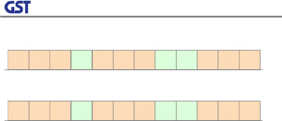
2.2.5 Frequency Selection
[Figure 7] PCS Band Structure
Based on the band select function, 5MHz, 10MHz, and 15MHz bands can be selected on the fo
llowing condition.
- Any 5MHz bands can be chosen in the all the blocks.
- 10MHz or 15MHz band can be selected in any combinations In the consecutive bands
- C1, C2 select is not supported.
A1 A2 A3 D B1 B2 B3 E F C3 C4 C5
1930MHz 1990MHz
A1 A2 A3 D B1 B2 B3 E F C3 C4 C5
1850MHz 1910MHz
< Downlink >
< Uplink >
16
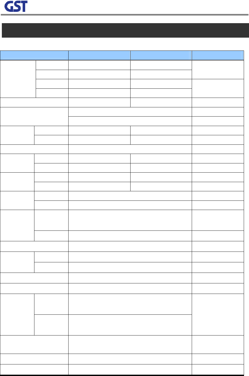
3. SPECIFICATIONS
3.1 System Specifications
Item Downlink Uplink Remark
A1 869 ~ 880 824 ~ 835
A2 890 ~ 891.5 845 ~ 846.5
B1 880 ~ 890 835 ~ 845
Cellular
Frequency
(MHz) B2 891.5 ~ 894 846.5 ~ 849
PCS Frequency (MHz) 1930 ~ 1990 1850 ~ 1910 Refer to Figure 7
A1+A2 or B1+B2
Sub Band Filtering 5, 10, 15MHz BW (tunable)
Cellular 79dB 84dB
Gain PCS 85dB 74dB
Flatness 5dB peak to peak Channel power
Cellular -49dBm ~ -81dBm Max -73dBm
Input Range PCS -48dBm ~ -85dBm Max -67dBm
Cellular 17dBm 17dBm Output
Power PCS 19dBm 17dBm
Cellular 23dB AGC
Range PCS 28dB
Cellular ≥45dBc@±2MHz
≥30dBc @±0.375MHz
Roll off
PCS ≥30dBc @±1.5MHz
Group Delay ≤ 5us
Cellular ≤-30dBm @±0.88MHz
Single &
2-tone PCS ≤-40dBm @±1.2MHz
Noise Figure ≤ 10dB @Max, Mean, Min Gain
Input Inter-modulation ≤ 10dB
Cellular ≥ 45dBc @ 750kHz
≥ 45dBc @ 1.98MHz
Adjacent
Channel
Power PCS ≥ 45dBc @ 885kHz
≥ 45dBc @ 1.98MHz
Radiated Spurious
Emissions ≤ -13dBm
Frequency Error ± 300Hz @cellular, ± 150Hz @PCS
Signal Quality Rho >0.98
17
3.2 Mechanical Specifications
Item Specification Remark
RF Connector N-Type Female Donor & Coverage ANT Port
AC Power Connector MS3102A-10SL (3Pin)
AC Supply AC 120V 60Hz
Out Dimension 17 x 12 x 4.6 Inch
Net Weight 16.5 Kg
Operation Temperature -10 ~ +50℃℃ Convection cooling
Humidity 5% ~ 85% Non-condensing
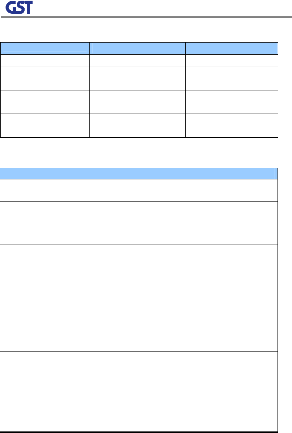
3.3 Functions
Item Description
Gain Control • Gain can be controlled between 40dB and 65dB
• Setting gain and current gain can be displayed.
AGC
(Auto Gain Control)
• Regardless of input changes output would be maintained constantly by
controlling its gain.
• AGC Value Setting Through GUI
• ON/OFF Setting Through GUI
ALC
(Auto Limit Control)
• User configurable output limit function
• ALC Level setting through GUI
• Output is greater than a setting value, and then automatically the gain is
reduced.
• Output is reduced, and then automatically the gain is recovered.
• The repeater output is greater than a setting value with a minimum gain.
Then the repeater would shut down.
Band Select
• User can select A-Band or B-Band in the cellular band.
• User can select consecutive 5, 10, 15MHz block in the all the 60MHz block
of the PCS band.
Output Detect
Function • The output of each path is displayed on GUI
Spurious Check
• In order for a repeater not to emit spurious waves more than –13dBm out of band,
monitoring the noise power.
• If spurious waves are greater than -13dBm, controlling its gain
• If spurious waves are greater than -13dBm with Minimum Gain, Repeater shuts
down
• Recovery Algorithm is working after shutdown
18
Oscillation Check
• When Initial Setup or Reset, Checking Isolation
• While Operation, Monitoring Oscillation through Highest and Lowest values
comparison of Noise Floor
• When Oscillation happens, automatically try stabilizing Isolation through
Repeater Gain Control
• If Oscillation still occurs with Minimum Gain, Repeater Shuts down
• Recovery Algorithm is working after shutdown
DL Input Detect
Function
• Monitoring downlink donor antenna input power
• Alarming if input range is abnormal or no signal is inputted.
Auto Recovery • When Repeater Shuts down, regularly recovering its output power and
checking its alarming situations
Temperature
Monitoring Function
• Monitoring current temperature
• User Configurable up limits and down limits
When the current temperature is out of range, Repeater shuts down
• When Temperature falls in the normal range, automatically it recovers its
functions.
VSWR Monitoring • When the VSWR of Forward output is abnormal, alarming and shutdown.
• Recovery Algorithm is working after shutdown
Power Supply
Monitoring • PSU current monitoring and the total current is over the standard, Alarming
Voltage Out of
Range Monitoring • PSU Low and High Power Alarm Function
LED Display • Repeater status is displayed through front LED
19
4. INSTALLATION
4.1 SYSTEM INSTALLATION
4.1.1 Contents of Box (1 SET)
Category Contents Quantity
Repeater COVERCELL 25K Repeater 1 EA
Accessory
Power Cable
Mounting Bracket
Screws
1 EA
1 EA
1 SET
USER MANUAL MANUAL 1 EA
4.1.2 Caution
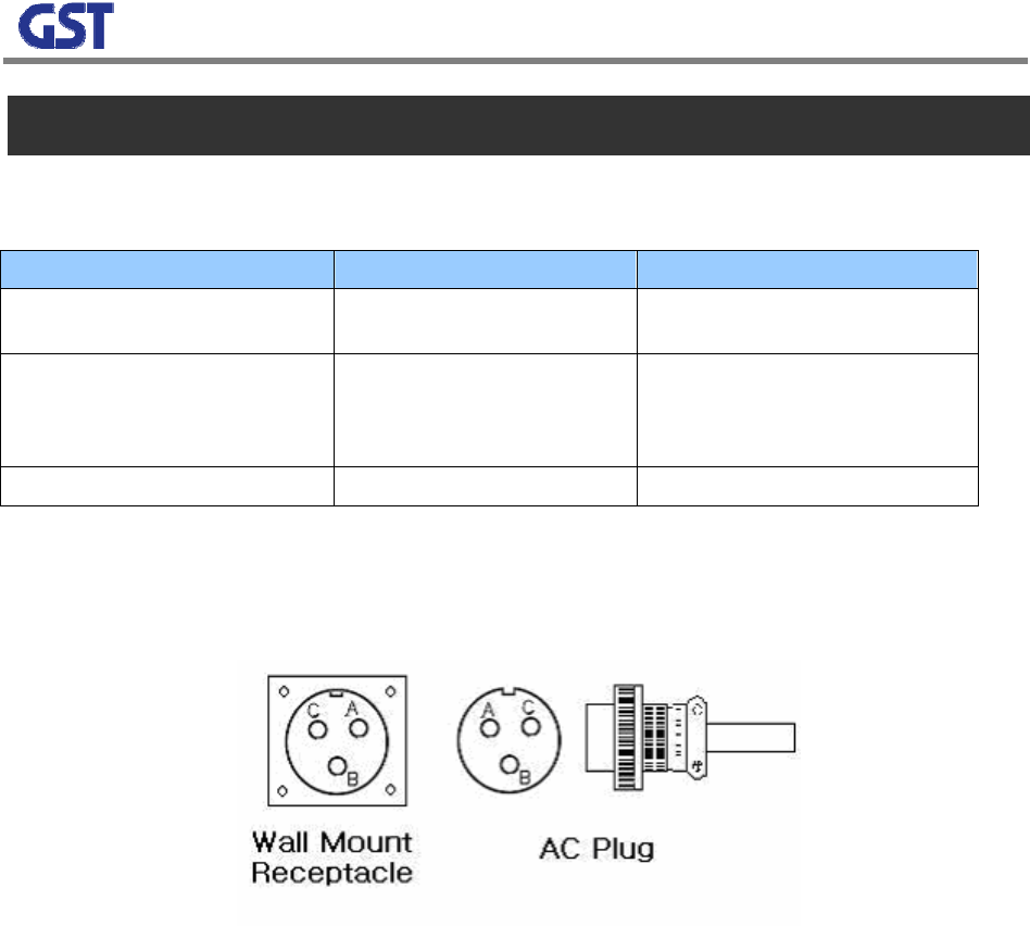
1) System Main Power Check: the main input power of this repeater is AC110V
A : 110V ~ 125VAC
B : 110V ~ 125VAC
C : GND
[Figure 8] MS 3100 A 10SL-3 (Wall Mount Receptacle) & MS3010 A 10SL-3(Plug)
2) Input Condition Optimization:
A. Cellular Forward Input Condition: -81 ~ -49dBm
B. PCS Forward Input Condition: -85 ~ -48dBm
C. Adjusting system input condition to be optimized after comparing a donor antenna input con
dition to A and B
3) Measuring Isolation between Donor/Coverage Antennas
A. Cellular: ≥96dBc(Gain +15dB)
B. PCS: ≥100dBc (Gain+15dB)
C. Checking the above conditions, adjusting system input condition to be optimized.
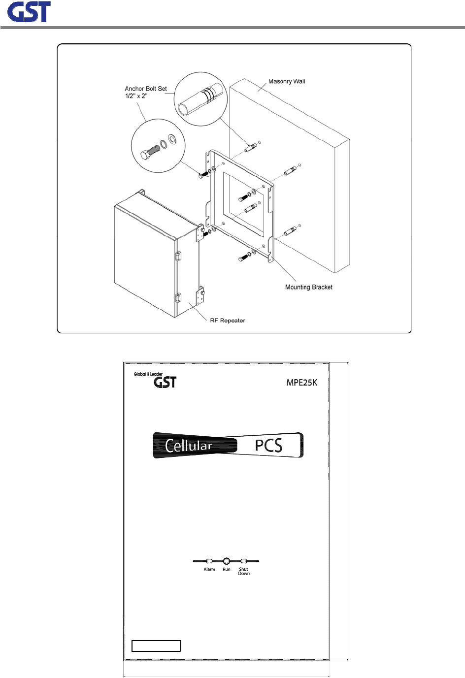
4) The standard installation of this repeater is vertically wall-typed.
20
[Figure 9] Dual-band In-building Repeater
434
300
GS Teletech Inc. Tech Support
1-866-9-GST-USA (toll free)
[Figure 10] Dual-band In-building Repeater
21
4.1.3 System Initiation
1) Check points after connecting networks
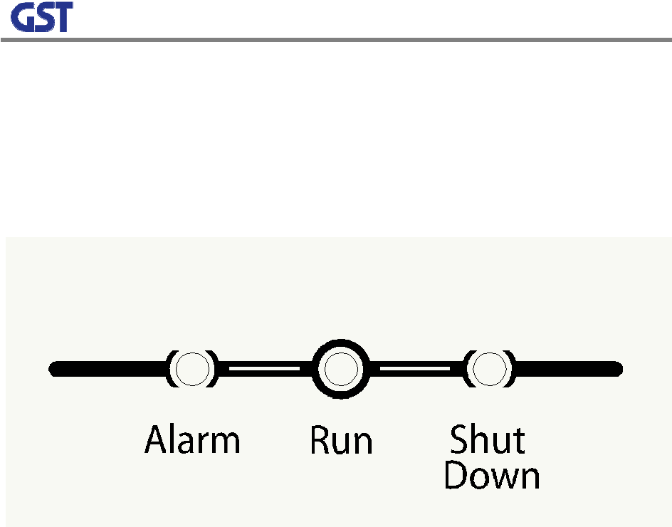
A. External LED
RUN: ①When Power On, green light blinks. Otherwise, the lamp is off.
ALARM: ②When alarming situations happen, the yellow light is on. Otherwise, it is off.
SHUT DOWN: When Shut Down③ situations occur, the yellow light is on. Otherwise, it is off.
[Figure 11] dual-band In-building Repeater Repeater Front LED
B. Checking through Debug Program
C. Checking output power
Checking output status through output monitoring port and the characteristics of unnecessary wavefor
ms using a spectrum analyzer
D. Checking service quality status in the service area
Checking service signal quality status using terminals in the service area
4.2 TROUBLESHOOTING
When the repeater is abnormal, diagnosing with remote control or site debug functions. If major
alarms go off, turn it off and contact customer service at GS Teletech.
a. Troubleshooting should be performed by trained technicians.
b. No internal or external parts should be disassembled or tampered with for any reason.
c. While troubleshooting, technician should use attenuator to check RF Signal output.