GS Instech GSTR1930DT-SPR CDMA In-Building RF Repeater User Manual 1
GS Instruments Co., Ltd. CDMA In-Building RF Repeater 1
UserManual.wiki
>
GS Instech
>
GSTR1930DT SPR User Manual
User Manual
Navigation menu
Upload a User Manual
Namespaces
Wiki Guide
HTML
PDF
Info
Views
User Manual
Discussion / Help
Navigation
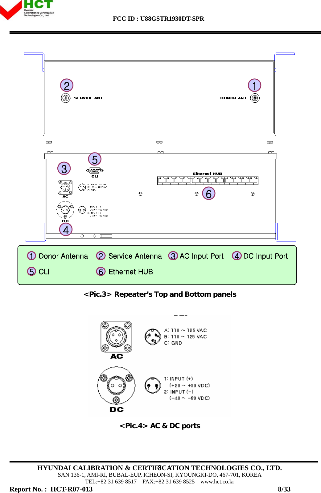
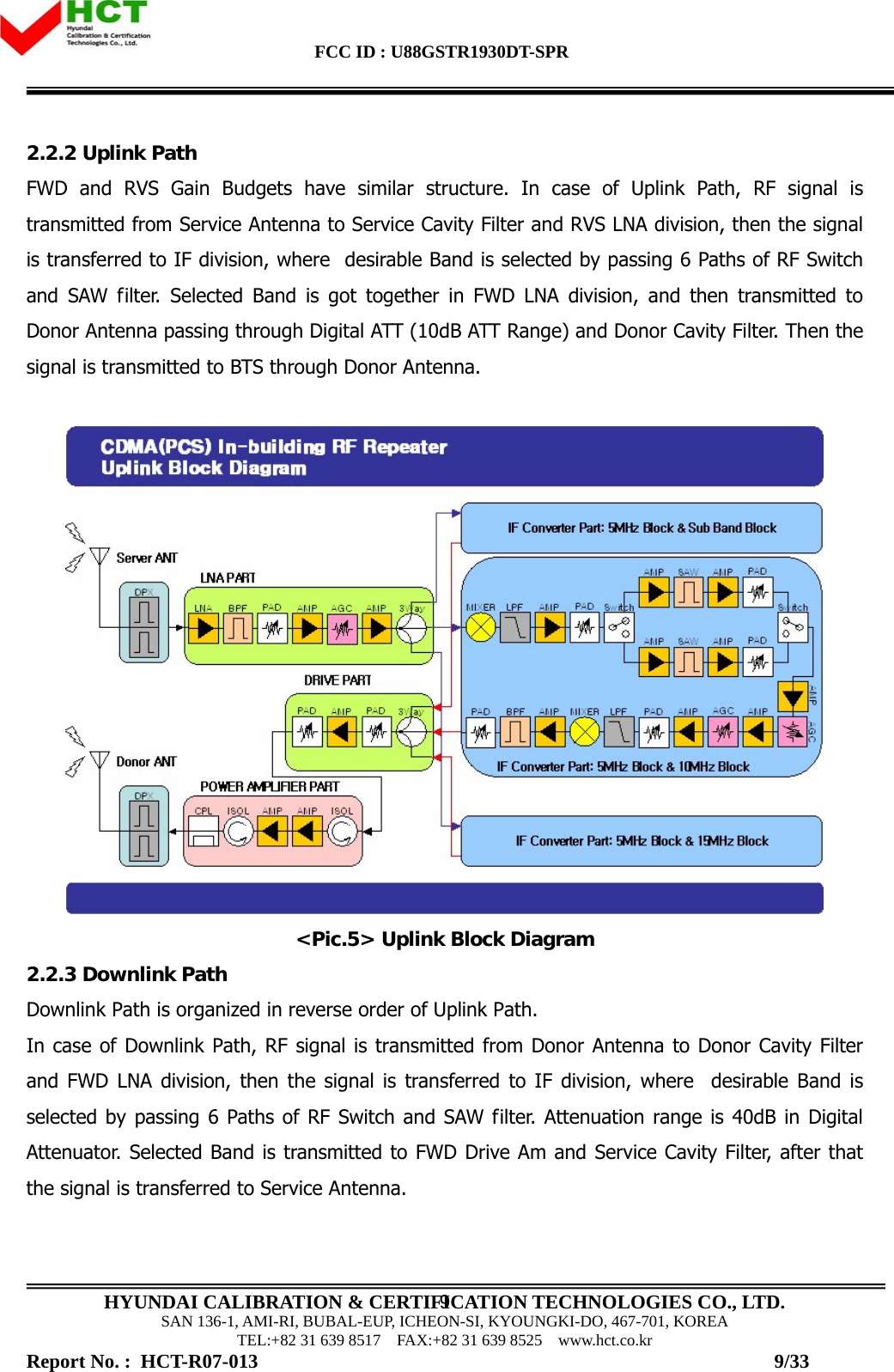
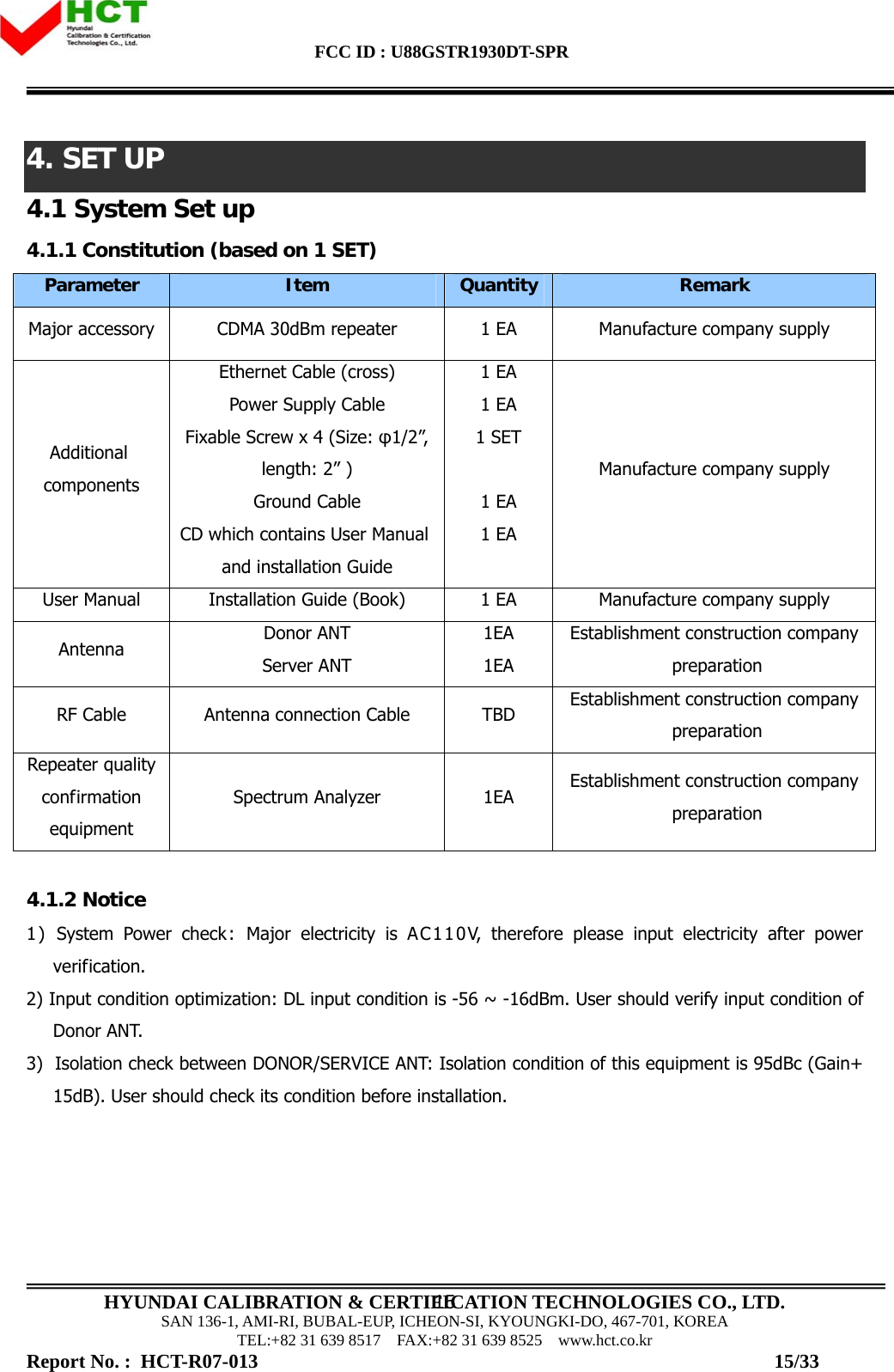
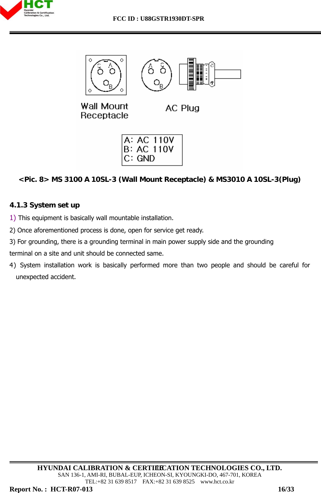
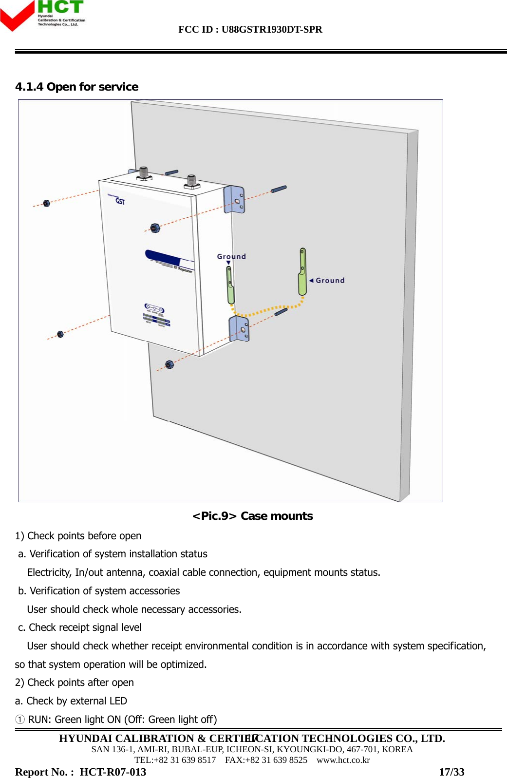
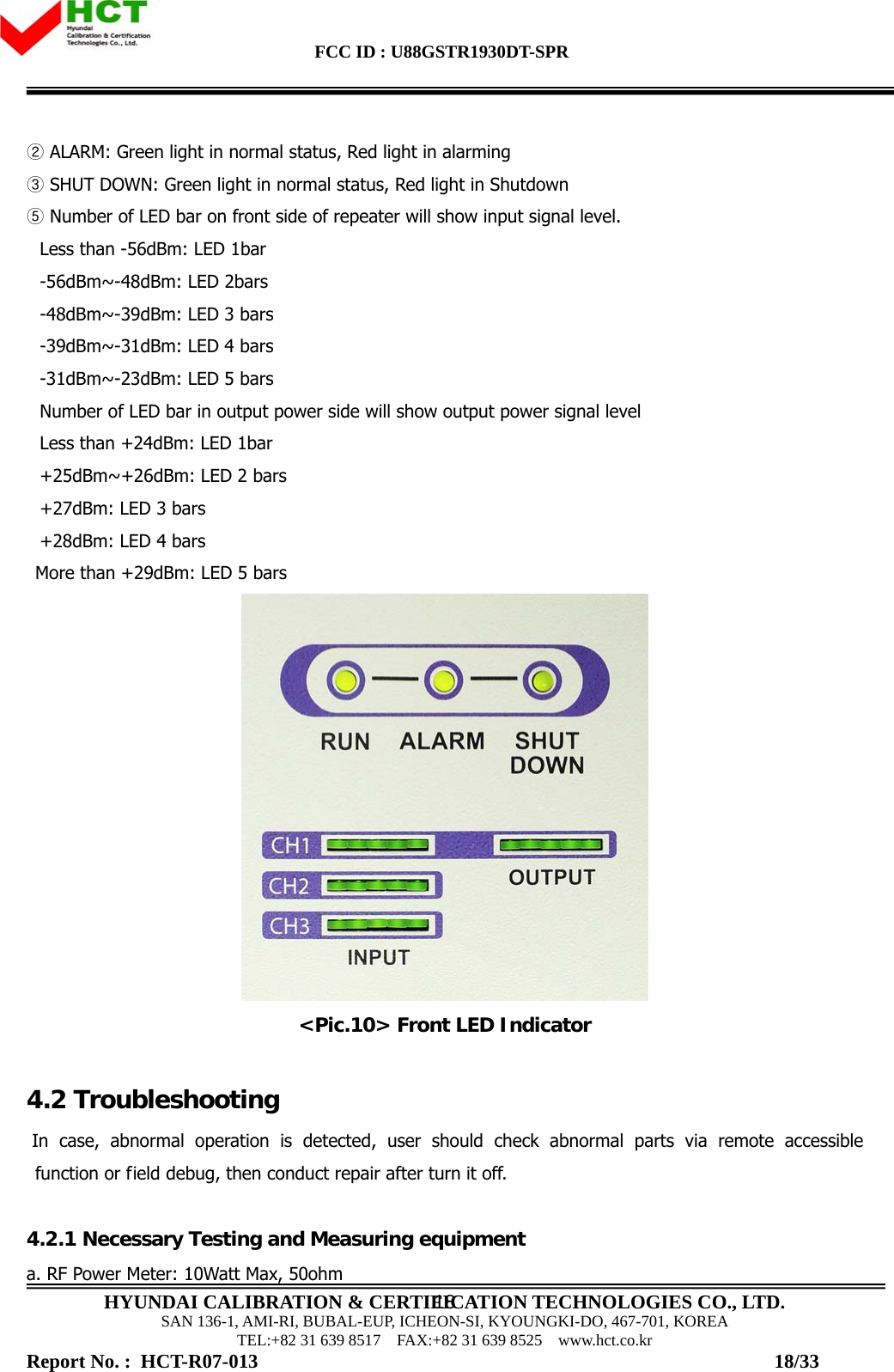
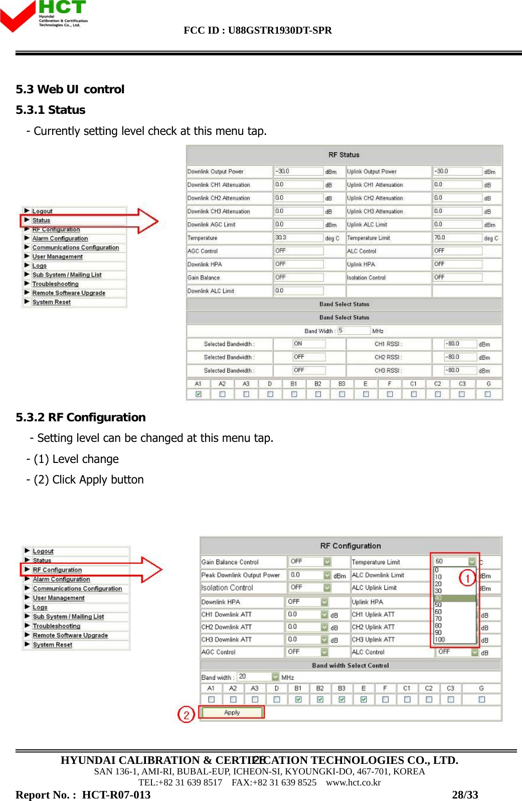
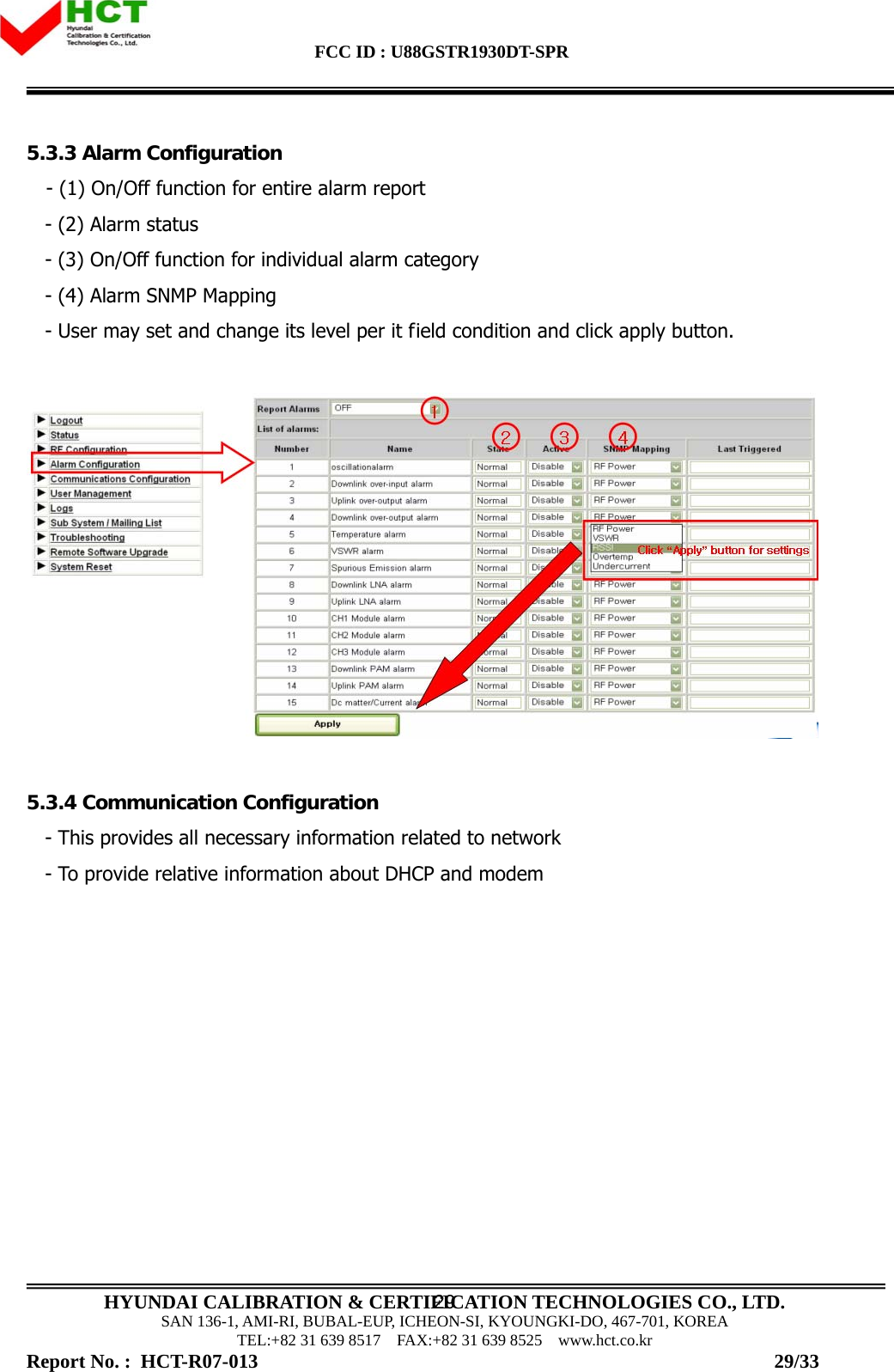
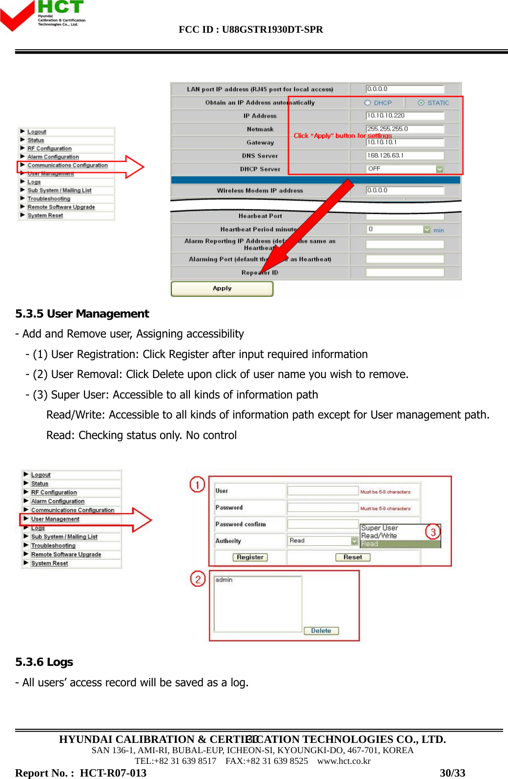
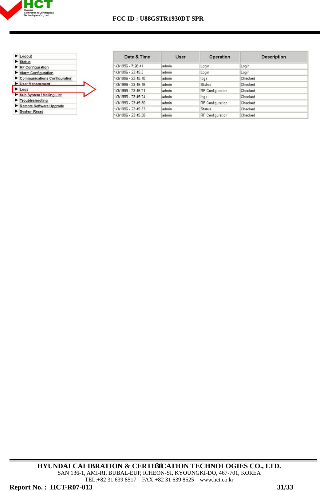
![FCC ID : U88GSTR1930DT-SPR HYUNDAI CALIBRATION & CERTIFICATION TECHNOLOGIES CO., LTD. SAN 136-1, AMI-RI, BUBAL-EUP, ICHEON-SI, KYOUNGKI-DO, 467-701, KOREA TEL:+82 31 639 8517 FAX:+82 31 639 8525 www.hct.co.kr 10 <Pic.6> Downlink Block Diagram 2.2.4 US PCS Frequency Selection 1930AB CDEF G1945 1950 1965 1970 1975 1990 1995 < Forward Band Structure >f (MHz) 1930B CDEF GA1945 1950 1965 1970 1975 1990 1995 < Forward Band Structure >f (MHz) 1850 AB CDEF G1865 1870 1885 1890 1895 1910 1915 f (MHz) < Reverse Band Structure >1850 B CDEF GA1865 1870 1885 1890 1895 1910 1915 f (MHz) < Reverse Band Structure > <Pic.7> PCS Band Structure US PCS 1900 repeater has 5MHz, 10MHz, 15MHz, 20MHz Paths in IF division, so any of these bandwidths can be chosen for providing service. But there are some cases when this choice is not applicable. - Not continuous 4 Paths [5 MHz each], so total band is 20MHz (i.e. A1A3B2C1, A1A2B1B2) Report No. : HCT-R07-013 10/33](https://usermanual.wiki/GS-Instech/GSTR1930DT-SPR/User-Guide-810013-Page-10.png)