GS Instech GSTR1930DT-SPR CDMA In-Building RF Repeater User Manual 1
GS Instruments Co., Ltd. CDMA In-Building RF Repeater 1
User Manual

FCC ID : U88GSTR1930DT-SPR
HYUNDAI CALIBRATION & CERTIFICATION TECHNOLOGIES CO., LTD.
SAN 136-1, AMI-RI, BUBAL-EUP, ICHEON-SI, KYOUNGKI-DO, 467-701, KOREA
TEL:+82 31 639 8517 FAX:+82 31 639 8525 www.hct.co.kr
ATTACHMENT E.
- USER MANUAL -
Report No. : HCT-R07-013 1/33

FCC ID : U88GSTR1930DT-SPR
HYUNDAI CALIBRATION & CERTIFICATION TECHNOLOGIES CO., LTD.
SAN 136-1, AMI-RI, BUBAL-EUP, ICHEON-SI, KYOUNGKI-DO, 467-701, KOREA
TEL:+82 31 639 8517 FAX:+82 31 639 8525 www.hct.co.kr
2
INFORMATION TO USER :
NOTE: This equipment has been tested and found to comply with the limits for a Class A digital
device, pursuant to Part 15 of the FCC Rules. These limits are designed to provide reasonable
protection against harmful interference when the equipment is operated in a commercial
environment. This equipment generates, uses, and can radiate radio frequency energy and, if
not installed and used in accordance with the instruction manual, may cause harmful
interference to radio communications. Operation of this equipment in a residential area is likely
to cause harmful interference in which case the user will be required to correct the interference
at his own expense.
CAUTION
Changes or modifications not expressly approved
by the manufacturer responsible for compliance
could void the user's authority to operate the equipment
Report No. : HCT-R07-013 2/33

FCC ID : U88GSTR1930DT-SPR
HYUNDAI CALIBRATION & CERTIFICATION TECHNOLOGIES CO., LTD.
SAN 136-1, AMI-RI, BUBAL-EUP, ICHEON-SI, KYOUNGKI-DO, 467-701, KOREA
TEL:+82 31 639 8517 FAX:+82 31 639 8525 www.hct.co.kr
3
- INDEX -
1. SUMMARY .................................................................................................................4
2. SYSTEM CONFIGURATION.....................................................................................6
3. SPECIFICATIONS...................................................................................................11
3.1 System Specifications (applicable to both Uplink & Downlink)................................................... 11
3.2 Electrical and Environment Specifications .......................................................................................... 11
3.3 Functions..........................................................................................................................................................12
4. SET UP .....................................................................................................................15
4.1 System Set up ................................................................................................................................................15
4.2 Troubleshooting ............................................................................................................................................18
5. WEB USER INTERFACE .........................................................................................25
5.1 IP Address verification and Explorer setting......................................................................................25
5.2 PCS Web UI.....................................................................................................................................................27
Report No. : HCT-R07-013 3/33

FCC ID : U88GSTR1930DT-SPR
HYUNDAI CALIBRATION & CERTIFICATION TECHNOLOGIES CO., LTD.
SAN 136-1, AMI-RI, BUBAL-EUP, ICHEON-SI, KYOUNGKI-DO, 467-701, KOREA
TEL:+82 31 639 8517 FAX:+82 31 639 8525 www.hct.co.kr
4
1. SUMMARY
US PCS 1900 RF repeater is an analog RF repeater, which improves PCS network.
US PCS 1900 RF repeater receives RF signal from BTS and transmits it to the blanked and
shadowed area, thus providing and improving voice and image data services. US PCS 1900 RF
repeater’s goal is to support BTS’s functions proportionately.
US PCS 1900 RF repeater communicates with BTS wirelessly, thus saving additional costs for its
maintenance.
US PCS 1900 RF repeater consists of PA (Downlink, Uplink), IF, LNA (Downlink, Uplink), I/O &
Control divisions, which are supplied with Alarm LED, thus providing quick and easy
maintenance and troubleshooting of the repeater.
This manual describes in general structure of US PCS1900 repeater, its application, maintenance
and troubleshooting, installation and operation etc.
Abbreviation
PAM: POWER AMPLIFIER MODULE
LNA: LOW NOISE AMPLIFIER
AGC: AUTO GAIN CONTROL
ALC: AUTO LIMIT CONTROL
Report No. : HCT-R07-013 4/33

FCC ID : U88GSTR1930DT-SPR
HYUNDAI CALIBRATION & CERTIFICATION TECHNOLOGIES CO., LTD.
SAN 136-1, AMI-RI, BUBAL-EUP, ICHEON-SI, KYOUNGKI-DO, 467-701, KOREA
TEL:+82 31 639 8517 FAX:+82 31 639 8525 www.hct.co.kr
5
Ethernet Instruction “ This equipment is indoor use and all the communication wirings
are limited to inside of the building” or similar texts.
For PLUGGABLE EQUIPMENT, the socket-outlet shall be installed near the
equipment and shall be easily accessible.
Replaceable batteries instruction
CAUTION
RISK OF EXPLOSION IF BATTERY IS REPLACED BY AN INCORRECTIVE TYPE.
DISPOSE OF USED BATTERIES ACCORDING TO THE INSTRUCTIONS
Report No. : HCT-R07-013 5/33
FCC ID : U88GSTR1930DT-SPR
HYUNDAI CALIBRATION & CERTIFICATION TECHNOLOGIES CO., LTD.
SAN 136-1, AMI-RI, BUBAL-EUP, ICHEON-SI, KYOUNGKI-DO, 467-701, KOREA
TEL:+82 31 639 8517 FAX:+82 31 639 8525 www.hct.co.kr
6
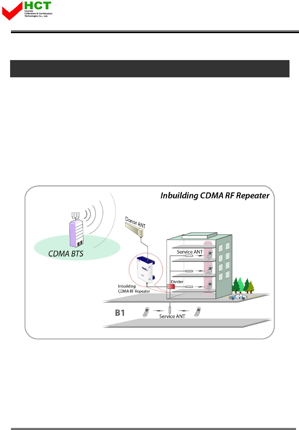
2. System Configuration
2.1 US PCS 1900 service organization
US PCS 1900 repeater decreases blanked and shadowed areas and extends cell coverage by re-
transmitting signal. The signal is received from BTS via Antenna directly, thus excluding
additional expenses for signal transmission (like cabling). Service organization of CDMA In-
building RF repeater is shown at the picture below. Donor Antenna is directed to BTS, and being
divided at Service Antennas are installed in the building and parking place. Pass Loss should be
taken into consideration while dividing and cabling.
<Pic.1> US PCS 1900 Service organization
Report No. : HCT-R07-013 6/33
FCC ID : U88GSTR1930DT-SPR
HYUNDAI CALIBRATION & CERTIFICATION TECHNOLOGIES CO., LTD.
SAN 136-1, AMI-RI, BUBAL-EUP, ICHEON-SI, KYOUNGKI-DO, 467-701, KOREA
TEL:+82 31 639 8517 FAX:+82 31 639 8525 www.hct.co.kr
7
2.2 System Design and Operation
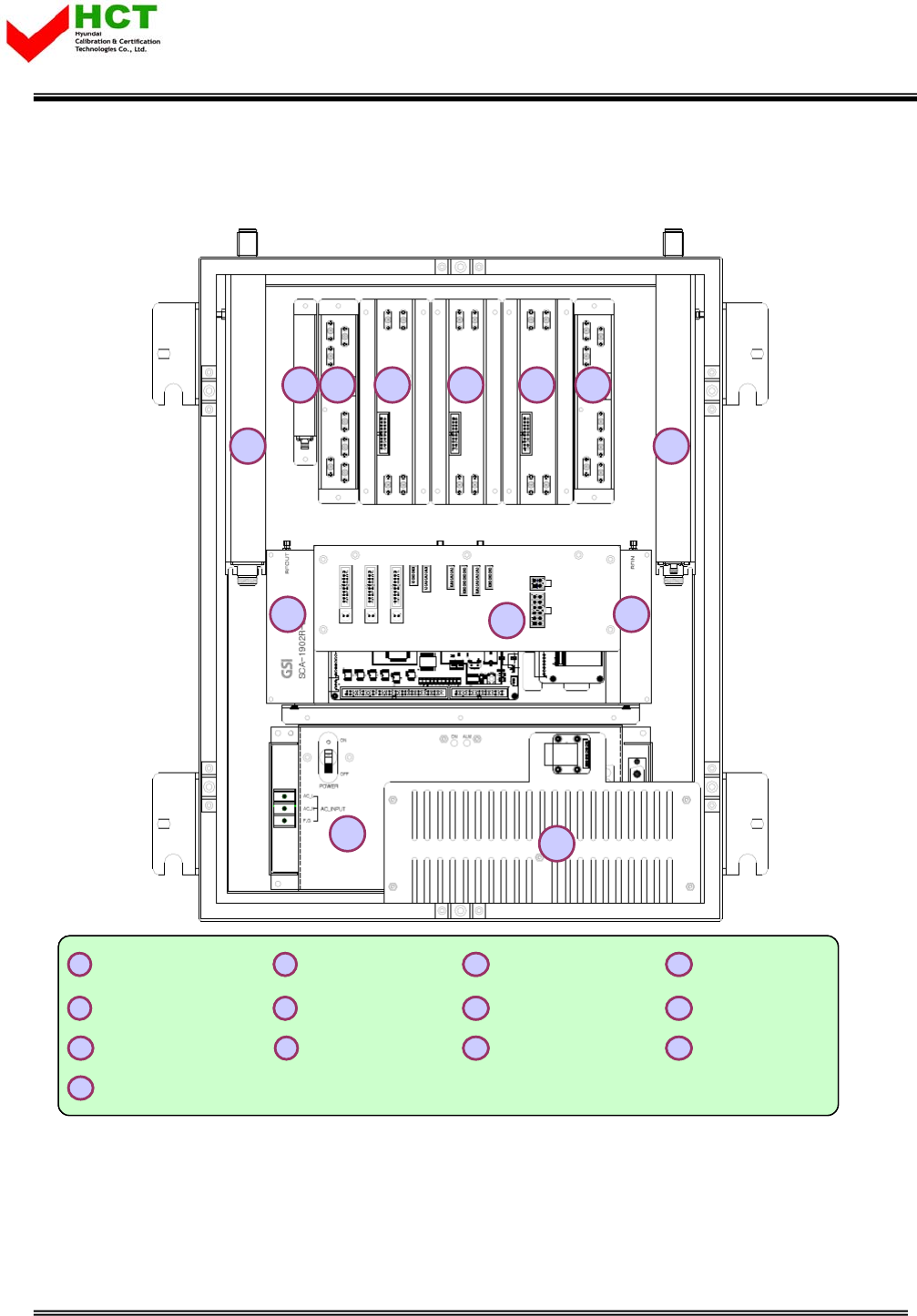
2.2.1 System design
1Donor Cavity 2Service Cavity 3I/O & NMS Board 4IF-10MHz
5IF-15MHz 6IF-20MHz 7RVS LNA 8FWD LNA
9Waveform Detector 10 FWD HPA 11 RVS HPA 12 Power Supply
13 HUB
12
3
4567 89
10 11
12 13
1Donor Cavity 2Service Cavity 3I/O & NMS Board 4IF-10MHz
5IF-15MHz 6IF-20MHz 7RVS LNA 8FWD LNA
9Waveform Detector 10 FWD HPA 11 RVS HPA 12 Power Supply
13 HUB
1Donor Cavity
1Donor Cavity 2Service Cavity
2Service Cavity 3I/O & NMS Board
3I/O & NMS Board 4IF-10MHz
4IF-10MHz
5IF-15MHz
5IF-15MHz 6IF-20MHz
6IF-20MHz 7RVS LNA
7RVS LNA 8FWD LNA
8FWD LNA
9Waveform Detector
9Waveform Detector 10 FWD HPA
10 FWD HPA 11 RVS HPA
11 RVS HPA 12 Power Supply
12 Power Supply
13 HUB
13 HUB
12
3
4567 89
10 11
12 13
<Pic.2> Repeater’s inside structure
Report No. : HCT-R07-013 7/33
FCC ID : U88GSTR1930DT-SPR
HYUNDAI CALIBRATION & CERTIFICATION TECHNOLOGIES CO., LTD.
SAN 136-1, AMI-RI, BUBAL-EUP, ICHEON-SI, KYOUNGKI-DO, 467-701, KOREA
TEL:+82 31 639 8517 FAX:+82 31 639 8525 www.hct.co.kr
8
2 1
3
4
5
6
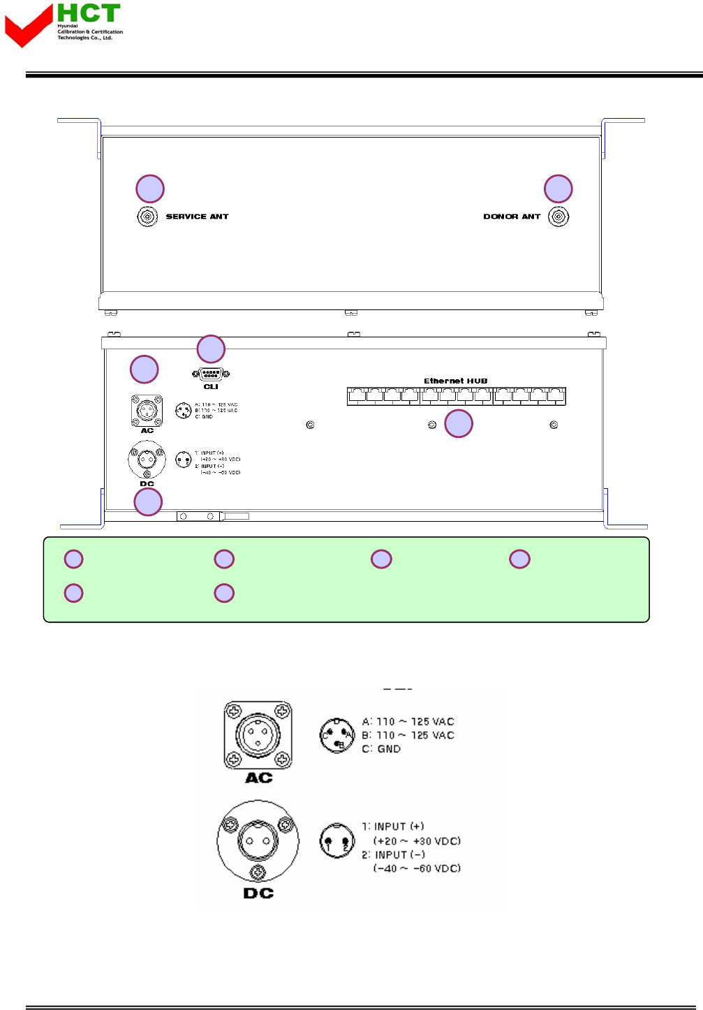
1Donor Antenna 2Service Antenna 3AC Input Port 4DC Input Port
5CLI 6Ethernet HUB
2 1
3
4
5
6
1Donor Antenna 2Service Antenna 3AC Input Port 4DC Input Port
5CLI 6Ethernet HUB
1Donor Antenna
1Donor Antenna 2Service Antenna
2Service Antenna 3AC Input Port
3AC Input Port 4DC Input Port
4DC Input Port
5CLI
5CLI 6Ethernet HUB
6Ethernet HUB
<Pic.3> Repeater’s Top and Bottom panels
<Pic.4> AC & DC ports
Report No. : HCT-R07-013 8/33
FCC ID : U88GSTR1930DT-SPR
HYUNDAI CALIBRATION & CERTIFICATION TECHNOLOGIES CO., LTD.
SAN 136-1, AMI-RI, BUBAL-EUP, ICHEON-SI, KYOUNGKI-DO, 467-701, KOREA
TEL:+82 31 639 8517 FAX:+82 31 639 8525 www.hct.co.kr
9
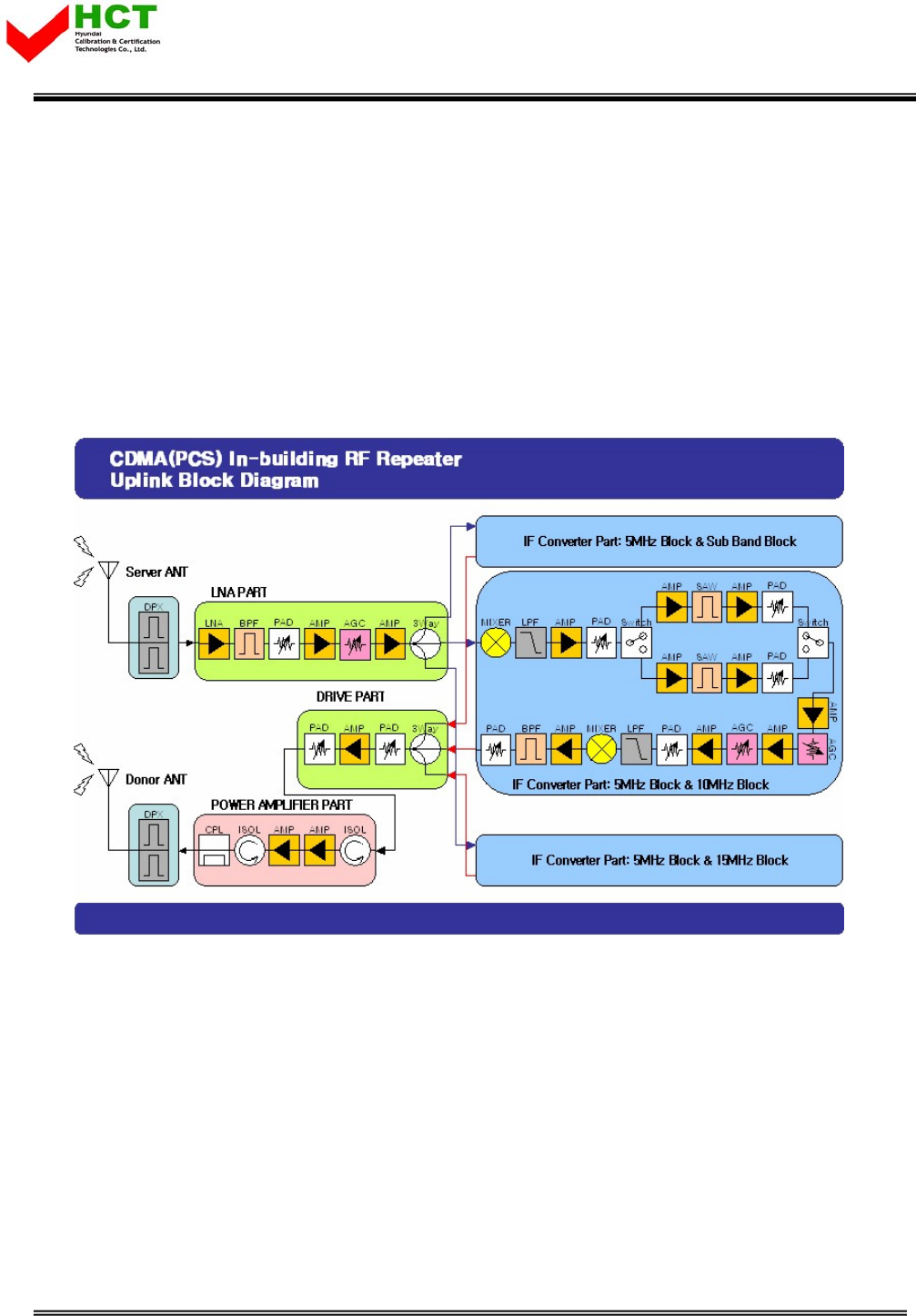
2.2.2 Uplink Path
FWD and RVS Gain Budgets have similar structure. In case of Uplink Path, RF signal is
transmitted from Service Antenna to Service Cavity Filter and RVS LNA division, then the signal
is transferred to IF division, where desirable Band is selected by passing 6 Paths of RF Switch
and SAW filter. Selected Band is got together in FWD LNA division, and then transmitted to
Donor Antenna passing through Digital ATT (10dB ATT Range) and Donor Cavity Filter. Then the
signal is transmitted to BTS through Donor Antenna.
<Pic.5> Uplink Block Diagram
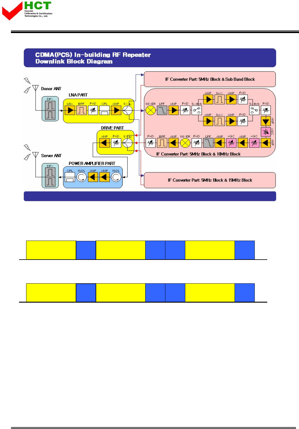
2.2.3 Downlink Path
Downlink Path is organized in reverse order of Uplink Path.
In case of Downlink Path, RF signal is transmitted from Donor Antenna to Donor Cavity Filter
and FWD LNA division, then the signal is transferred to IF division, where desirable Band is
selected by passing 6 Paths of RF Switch and SAW filter. Attenuation range is 40dB in Digital
Attenuator. Selected Band is transmitted to FWD Drive Am and Service Cavity Filter, after that
the signal is transferred to Service Antenna.
Report No. : HCT-R07-013 9/33
FCC ID : U88GSTR1930DT-SPR
HYUNDAI CALIBRATION & CERTIFICATION TECHNOLOGIES CO., LTD.
SAN 136-1, AMI-RI, BUBAL-EUP, ICHEON-SI, KYOUNGKI-DO, 467-701, KOREA
TEL:+82 31 639 8517 FAX:+82 31 639 8525 www.hct.co.kr
10
<Pic.6> Downlink Block Diagram
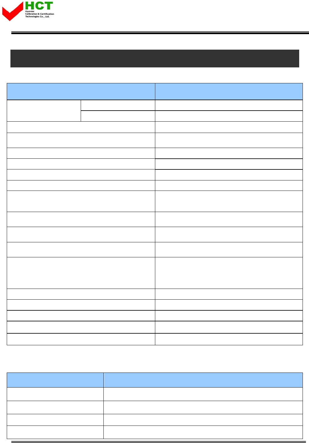
2.2.4 US PCS Frequency Selection
1930
AB CDEF G
1945 1950 1965 1970 1975 1990 1995
< Forward Band Structure >
f (MHz)
1930
B CDEF GA
1945 1950 1965 1970 1975 1990 1995
< Forward Band Structure >
f (MHz)
1850
AB CDEF G
1865 1870 1885 1890 1895 1910 1915 f (MHz)
< Reverse Band Structure >
1850
B CDEF GA
1865 1870 1885 1890 1895 1910 1915 f (MHz)
< Reverse Band Structure >
<Pic.7> PCS Band Structure
US PCS 1900 repeater has 5MHz, 10MHz, 15MHz, 20MHz Paths in IF division, so any of these
bandwidths can be chosen for providing service. But there are some cases when this choice is
not applicable.
- Not continuous 4 Paths [5 MHz each], so total band is 20MHz (i.e. A1A3B2C1,
A1A2B1B2)
Report No. : HCT-R07-013 10/33
FCC ID : U88GSTR1930DT-SPR
HYUNDAI CALIBRATION & CERTIFICATION TECHNOLOGIES CO., LTD.
SAN 136-1, AMI-RI, BUBAL-EUP, ICHEON-SI, KYOUNGKI-DO, 467-701, KOREA
TEL:+82 31 639 8517 FAX:+82 31 639 8525 www.hct.co.kr
11
3. SPECIFICATIONS
3.1 System Specifications (applicable to both Uplink & Downlink)
Characteristics Specification
Forward 1930 ~ 1995MHz
Frequency Range Reverse 1850 ~ 1915MHz
System Group Delay < 5㎲
Characteristic Impedance 50 ohm
VSWR Max1.5 : 1
Input Power Range -100 ~ -20dBm (for both Uplink and Downlink)
System Isolation > 90dB
Gain Range 50dB ~ 90 dB
Noise Figure < 4.5 dB @ Max Gain
<12 dB @Min Gain
Gain Adjustment Step(Accuracy) 1dB(±0.5dB)
Pass Band Ripple 2.5dB(±1.25dB)
Maximum Output Power 1W / 30dBm
Spurious Emissions
>45 dBc @885kHz
>55 dBc @1.98kHz
<-13dBm @Fc±2.25MHz (RBW: 1MHz)
IF Path 5MHz/10MHz/15MHz/20MHz
IF Frequency FWD: 200 MHz, RVS: 120MHz
Band Select Local Shift & RF Switching
Roll Offs > 50dBc @1MHz
Waveform Quality Factor min 0.912
3.2 Electrical and Environment Specifications
Characteristics Specification
Size(inch) / Type 16.1(W) x 20.5(L) x 6.1(H)
Power AC 120V 60Hz 5.5A
Temperature / Weight -10 ~+50/℃℃44.5lbs
Connector TYPE N Type Female
Report No. : HCT-R07-013 11/33
FCC ID : U88GSTR1930DT-SPR
HYUNDAI CALIBRATION & CERTIFICATION TECHNOLOGIES CO., LTD.
SAN 136-1, AMI-RI, BUBAL-EUP, ICHEON-SI, KYOUNGKI-DO, 467-701, KOREA
TEL:+82 31 639 8517 FAX:+82 31 639 8525 www.hct.co.kr
12
3.3 Functions
Parameter Specification
Gain Control • Adjustable DL and UL Gain range 50~90dB
• Display default Gain and current Gain function
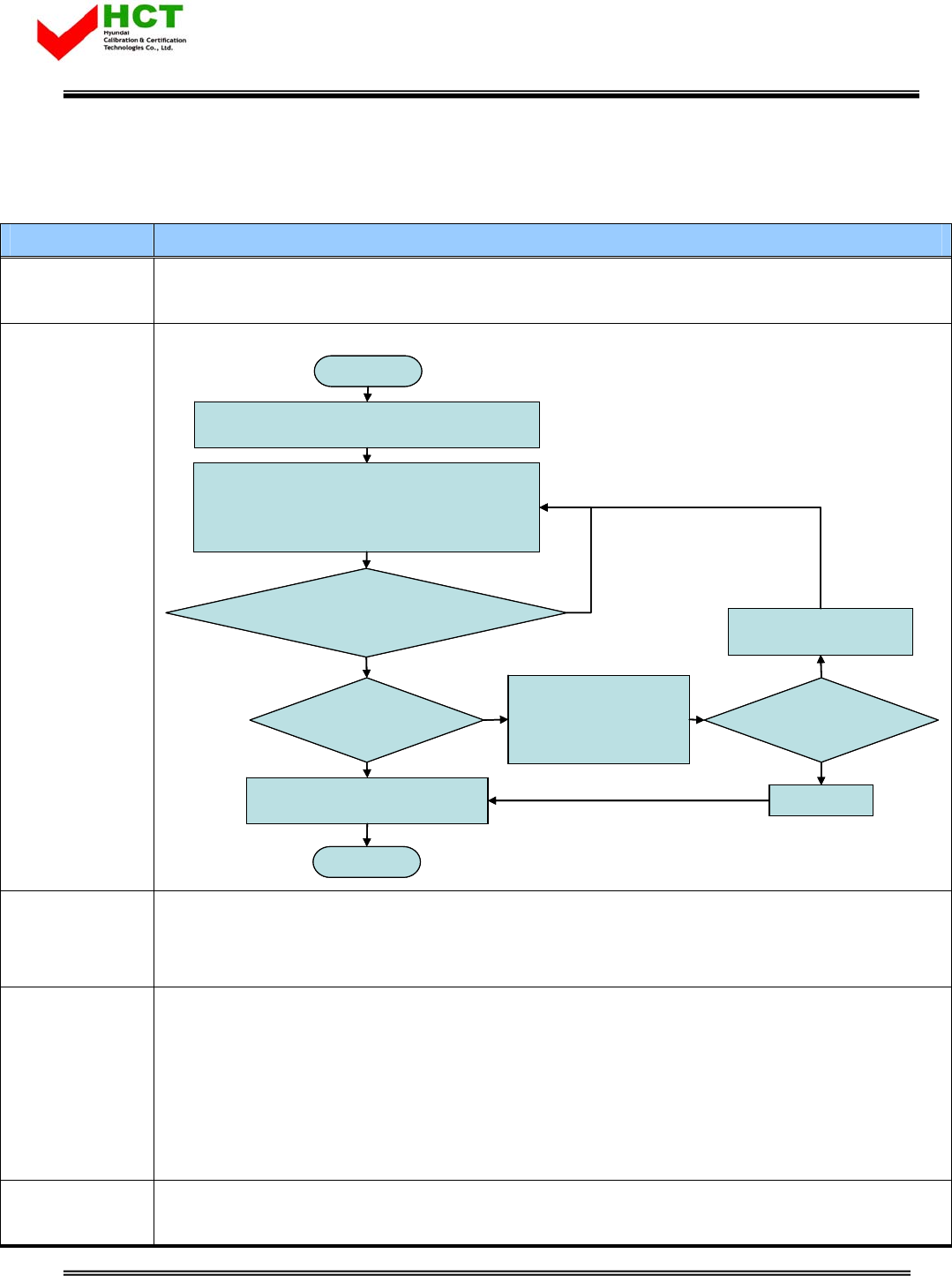
AGS
Auto Gain
Setting
• AGS (Auto Gain Setting) Use convenient Set-up
AGS (Auto Gain Setting)
→Installation time calculation: in AGS .
AGS start
D/L,U/L ATT: 0dB
HPA: ON, ALC: ON, Isolation Check: ON
Isolation generation: Wave detection using
noise floor level detect
Isolation analysis: isolation fault ÆSystem
Gain 1dB reduce
System Gain + 7dB<
isolation detection value
Max. Gain & isolation O.K
HPA: ON, Gain balance: ON,
AGC: ON, Shut-down: ON
AGS done
Gain reduce &
isolation O.K
Display Notice
HPA: Off
Current setting
maintenance
HPA: ON
Sever ANT Tuning
Re-installation: AGS
Yes
No
NoYes
No
Yes
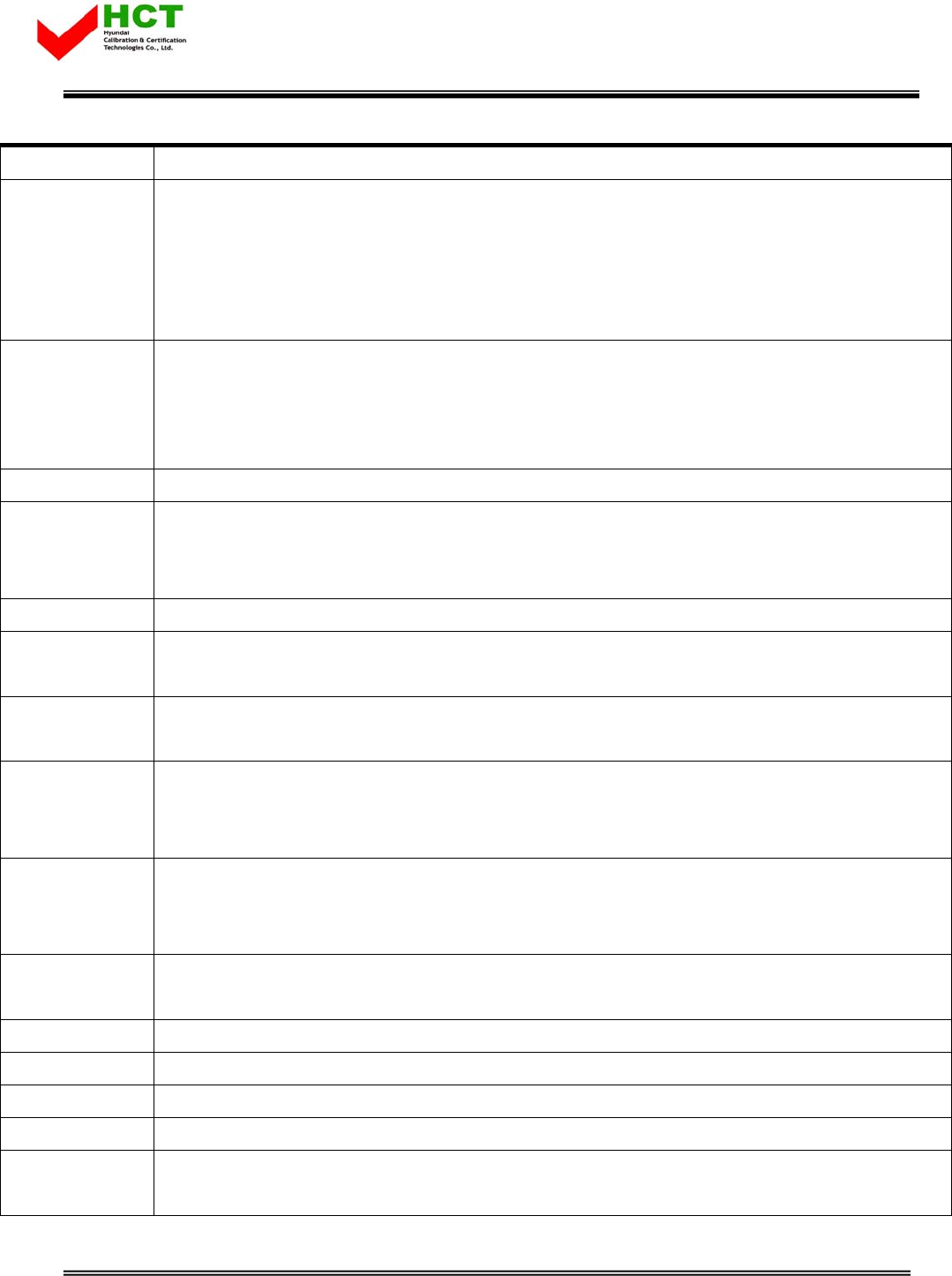
AGC
Auto Gain
Control
• It always operates in Downlink AGC ON status
• To maintain same Downlink output power despite flexible input signal strength.
• To add or subtract Attenuation level referring to AGC Power Limit level.
ALC
Auto Limit
Control
• To limit output power as far as default range
• Set up via GUI
• Automatic Gain decrement when output power of repeater is higher than default level
• Automatic Gain recovery when output power of repeater is reduced.
• Shutdown when output power is higher than default level in Minimum Gain
• Automatic Recovery Algorithm conversion after Shutdown status
Gain Balance • Downlink ATT is applied to Uplink during AGC state
• Setting and maintenance of output level
Report No. : HCT-R07-013 12/33
FCC ID : U88GSTR1930DT-SPR
HYUNDAI CALIBRATION & CERTIFICATION TECHNOLOGIES CO., LTD.
SAN 136-1, AMI-RI, BUBAL-EUP, ICHEON-SI, KYOUNGKI-DO, 467-701, KOREA
TEL:+82 31 639 8517 FAX:+82 31 639 8525 www.hct.co.kr
13
• Additional attenuation to ALC Level
Oscillation Check
• Isolation Check in initial set up or Reset
• Monitoring Oscillation comparing to minimum/maximum Noise Floor level
• When Oscillation occurred, repeater attempts to stabilize Isolation through Gain control function.
• Shutdown repeater when Oscillation still goes in Minimum Gain
• Automatic Recovery Algorithm conversion after Shutdown status
Spurious
Emission Alarm
• Noise Floor Observation in case of ±2.25MHz down at the center
• In case of Noise level > –13dBm, Spurious Emission is stabilized automatically
• In case of Oscillation Spurious Emission Alarming in Minimum Gain, repeater will be shutdown
• Automatically Switch to Recovery Algorithm at Shutdown
Band Select • To select either 5MHz/10MHz/15MHz/20MHz
Power
Monitoring
Function
• Monitoring repeater’s output level
DL Input control • Monitoring Donor ANT input power of DL
Automatic
Recovery
• When in repeater shutdown, it periodically recovers output power of repeater then monitors
alarming
Security • Support HTTPS for Web Browser security
• User authentication through User ID and Password
Temperature
control
• Monitoring temperature of repeater
• Maximum and minimum set up is possible. Shutdown in over temperature
• Automatic recovery after temperature becomes normal. (Hysteresis 10 degree)
VSWR
Monitoring
• Monitoring VSWR of Donor ANT Port (Every one and half minute)
• Reporting VSWR Alarm and Shutdown when the rate is 3:1
• Automatic Recovery Algorithm conversion after Shutdown status
IP address
report via E-mail
• When in PPP reconnection, E-mail which includes HTML to connect to newly assigned IP Address,
reports to operator.
DHCP Client • Automatic IP assignment
DHCP Server • Server function for automatic IP assignment
Web GUI • Remote and local user browser support through Web Browser
SNMP Agent • NMS report via SNMPv2 Trap
LED Display • LED displays power and operation status on front side of repeater system.
• DL input and output signal level is verified by LED bar.
Report No. : HCT-R07-013 13/33

FCC ID : U88GSTR1930DT-SPR
HYUNDAI CALIBRATION & CERTIFICATION TECHNOLOGIES CO., LTD.
SAN 136-1, AMI-RI, BUBAL-EUP, ICHEON-SI, KYOUNGKI-DO, 467-701, KOREA
TEL:+82 31 639 8517 FAX:+82 31 639 8525 www.hct.co.kr
14
Report No. : HCT-R07-013 14/33
FCC ID : U88GSTR1930DT-SPR
HYUNDAI CALIBRATION & CERTIFICATION TECHNOLOGIES CO., LTD.
SAN 136-1, AMI-RI, BUBAL-EUP, ICHEON-SI, KYOUNGKI-DO, 467-701, KOREA
TEL:+82 31 639 8517 FAX:+82 31 639 8525 www.hct.co.kr
15
4. SET UP
4.1 System Set up
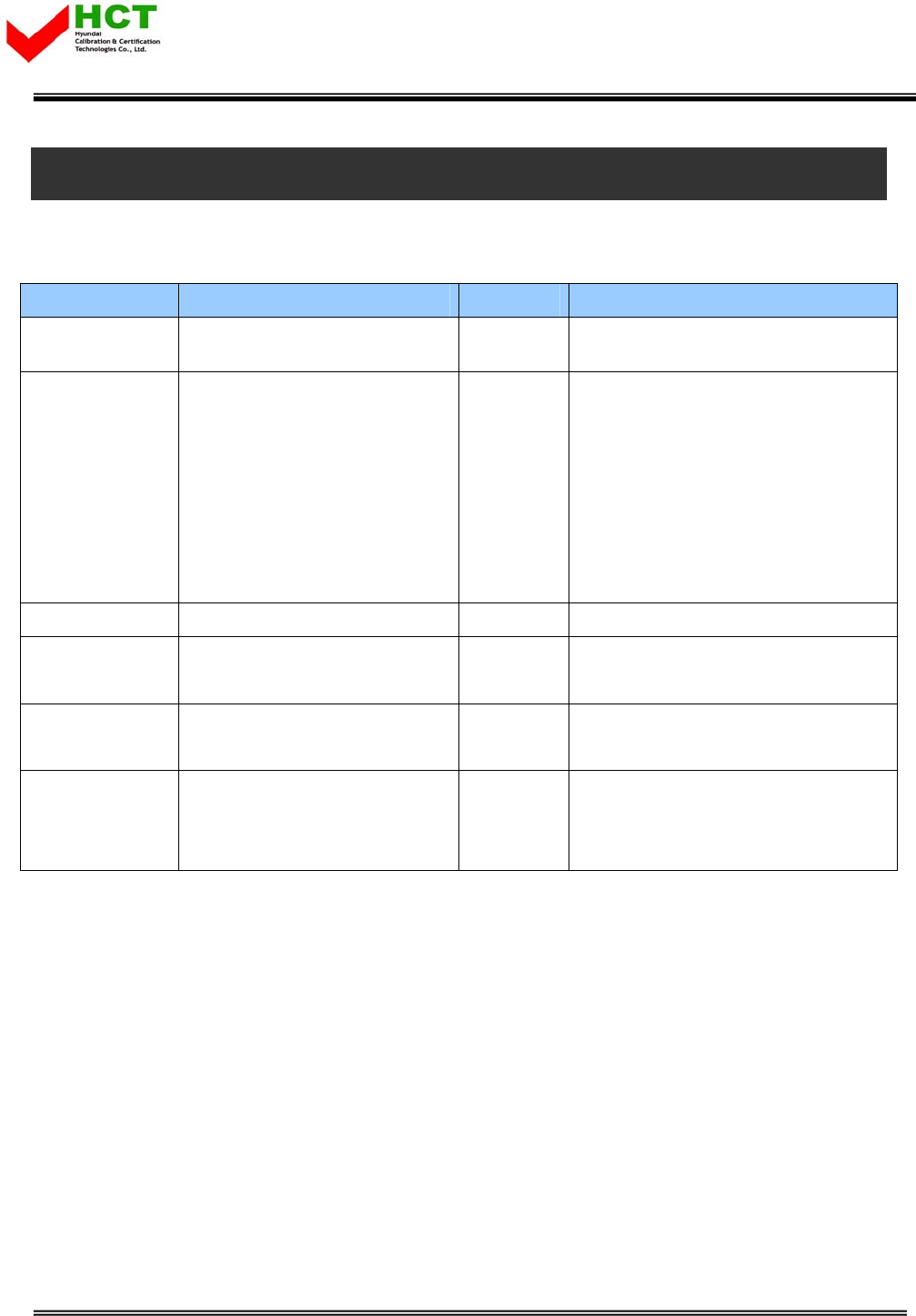
4.1.1 Constitution (based on 1 SET)
Parameter Item Quantity Remark
Major accessory CDMA 30dBm repeater 1 EA Manufacture company supply
Additional
components
Ethernet Cable (cross)
Power Supply Cable
Fixable Screw x 4 (Size: φ1/2”,
length: 2” )
Ground Cable
CD which contains User Manual
and installation Guide
1 EA
1 EA
1 SET
1 EA
1 EA
Manufacture company supply
User Manual Installation Guide (Book) 1 EA Manufacture company supply
Antenna Donor ANT
Server ANT
1EA
1EA
Establishment construction company
preparation
RF Cable Antenna connection Cable TBD Establishment construction company
preparation
Repeater quality
confirmation
equipment
Spectrum Analyzer 1EA Establishment construction company
preparation
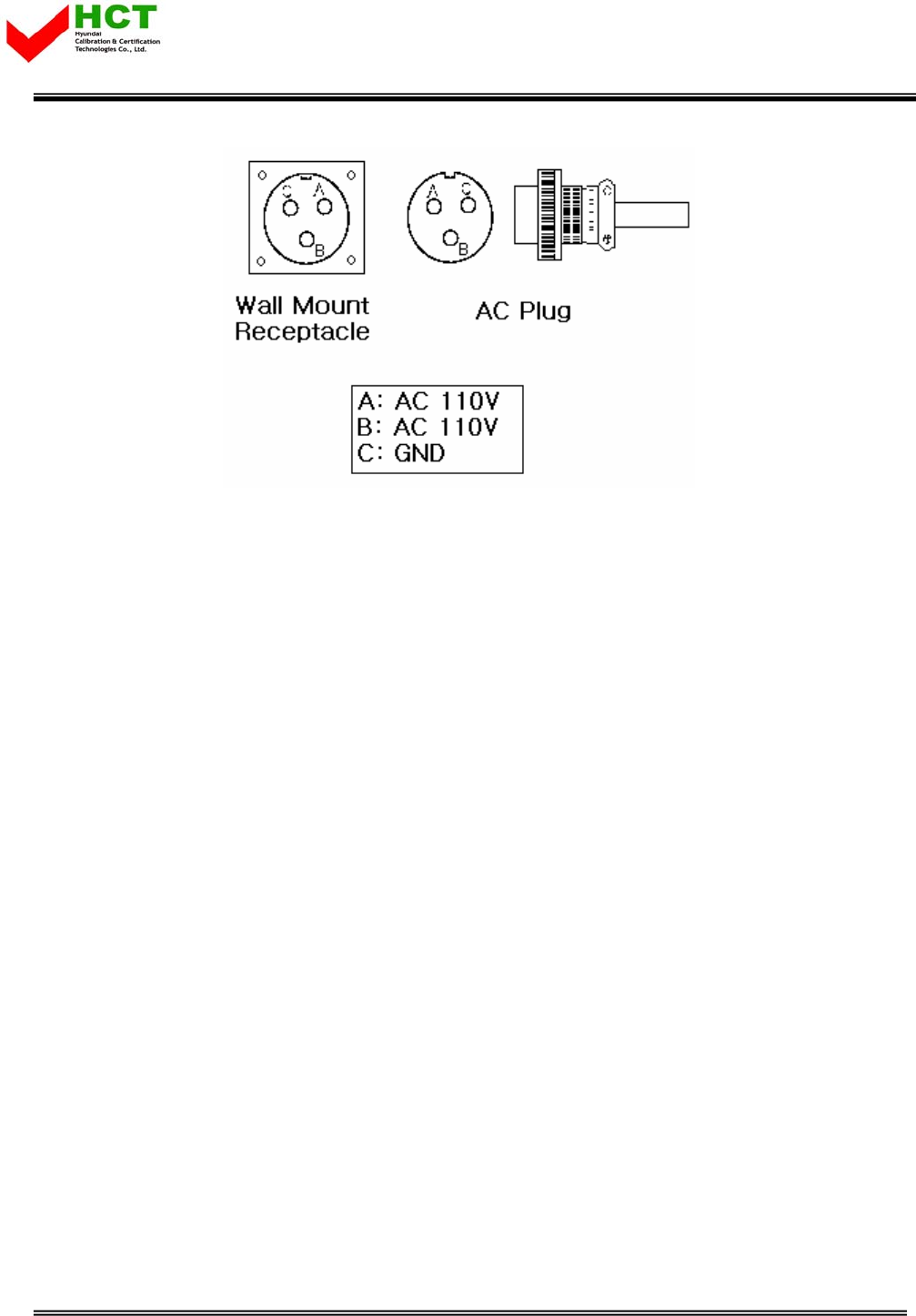
4.1.2 Notice
1) System Power check: Major electricity is AC110V, therefore please input electricity after power
verification.
2) Input condition optimization: DL input condition is -56 ~ -16dBm. User should verify input condition of
Donor ANT.
3) Isolation check between DONOR/SERVICE ANT: Isolation condition of this equipment is 95dBc (Gain+
15dB). User should check its condition before installation.
Report No. : HCT-R07-013 15/33
FCC ID : U88GSTR1930DT-SPR
HYUNDAI CALIBRATION & CERTIFICATION TECHNOLOGIES CO., LTD.
SAN 136-1, AMI-RI, BUBAL-EUP, ICHEON-SI, KYOUNGKI-DO, 467-701, KOREA
TEL:+82 31 639 8517 FAX:+82 31 639 8525 www.hct.co.kr
16
<Pic. 8> MS 3100 A 10SL-3 (Wall Mount Receptacle) & MS3010 A 10SL-3(Plug)
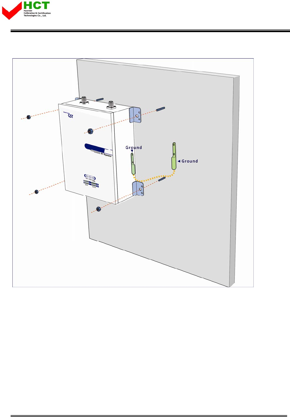
4.1.3 System set up
1) This equipment is basically wall mountable installation.
2) Once aforementioned process is done, open for service get ready.
3) For grounding, there is a grounding terminal in main power supply side and the grounding
terminal on a site and unit should be connected same.
4) System installation work is basically performed more than two people and should be careful for
unexpected accident.
Report No. : HCT-R07-013 16/33
FCC ID : U88GSTR1930DT-SPR
HYUNDAI CALIBRATION & CERTIFICATION TECHNOLOGIES CO., LTD.
SAN 136-1, AMI-RI, BUBAL-EUP, ICHEON-SI, KYOUNGKI-DO, 467-701, KOREA
TEL:+82 31 639 8517 FAX:+82 31 639 8525 www.hct.co.kr
17
4.1.4 Open for service
<Pic.9> Case mounts
1) Check points before open
a. Verification of system installation status
Electricity, In/out antenna, coaxial cable connection, equipment mounts status.
b. Verification of system accessories
User should check whole necessary accessories.
c. Check receipt signal level
User should check whether receipt environmental condition is in accordance with system specification,
so that system operation will be optimized.
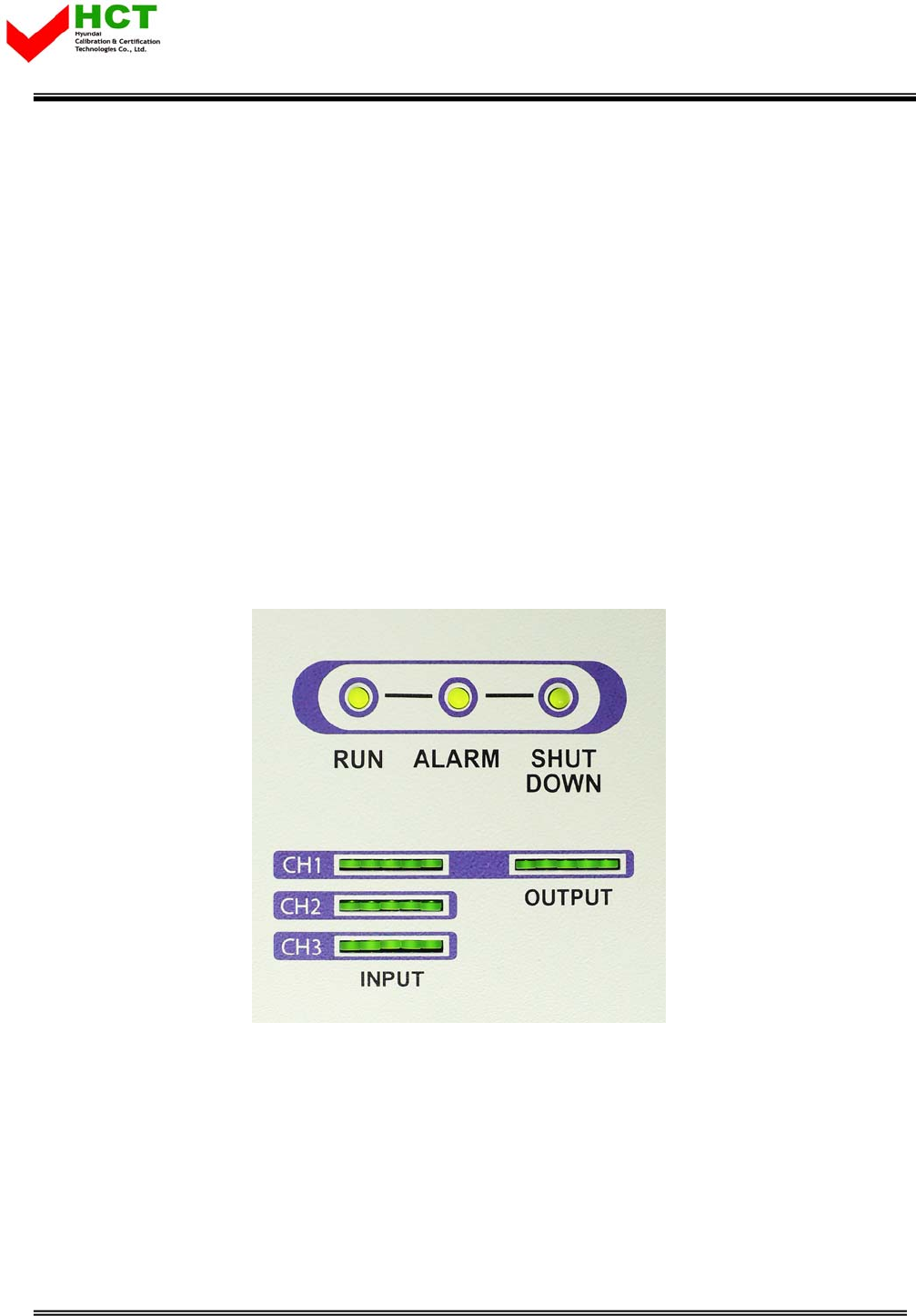
2) Check points after open
a. Check by external LED
RUN: Green light ON (Off: Green light off)①
Report No. : HCT-R07-013 17/33
FCC ID : U88GSTR1930DT-SPR
HYUNDAI CALIBRATION & CERTIFICATION TECHNOLOGIES CO., LTD.
SAN 136-1, AMI-RI, BUBAL-EUP, ICHEON-SI, KYOUNGKI-DO, 467-701, KOREA
TEL:+82 31 639 8517 FAX:+82 31 639 8525 www.hct.co.kr
18
ALARM: Green light in normal status, Red light in alarming②
SHUT DOWN: Green light i③n normal status, Red light in Shutdown
Number of LED bar on front side of repeater will show input signal level. ⑤
Less than -56dBm: LED 1bar
-56dBm~-48dBm: LED 2bars
-48dBm~-39dBm: LED 3 bars
-39dBm~-31dBm: LED 4 bars
-31dBm~-23dBm: LED 5 bars
Number of LED bar in output power side will show output power signal level
Less than +24dBm: LED 1bar
+25dBm~+26dBm: LED 2 bars
+27dBm: LED 3 bars
+28dBm: LED 4 bars
More than +29dBm: LED 5 bars
<Pic.10> Front LED Indicator
4.2 Troubleshooting
In case, abnormal operation is detected, user should check abnormal parts via remote accessible
function or field debug, then conduct repair after turn it off.
4.2.1 Necessary Testing and Measuring equipment
a. RF Power Meter: 10Watt Max, 50ohm
Report No. : HCT-R07-013 18/33
FCC ID : U88GSTR1930DT-SPR
HYUNDAI CALIBRATION & CERTIFICATION TECHNOLOGIES CO., LTD.
SAN 136-1, AMI-RI, BUBAL-EUP, ICHEON-SI, KYOUNGKI-DO, 467-701, KOREA
TEL:+82 31 639 8517 FAX:+82 31 639 8525 www.hct.co.kr
19
b. Signal Generator: 3GHz
c. Spectrum Analyzer: 3GHz
d. Multi Meter
4.2.2 Notice
a. Trouble shooting should be performed with drastic knowledge basis.
b. Unsure parts should not be disassembled.
c. When in trouble shooting, technician should use attenuator to check output side.
4.2.3 Note at set up process / Check point after open for service
Item Check Point Trouble shooting
Note
before
system
operation
* System Input power range
Input Level
D -1own Link 00dBm/Total ~ -20dBm/Total
U -1p Link 00dBm/Total ~ -20dBm/Total
Same as
above * System Gain
Gain
D 50own Link ~ 90dB
U 50p Link ~ 90dB
Same as
above * Output power at edge port side
Output power
D 30own Link dBm/Total
U 30p Link dBm/Total
Report No. : HCT-R07-013 19/33
FCC ID : U88GSTR1930DT-SPR
HYUNDAI CALIBRATION & CERTIFICATION TECHNOLOGIES CO., LTD.
SAN 136-1, AMI-RI, BUBAL-EUP, ICHEON-SI, KYOUNGKI-DO, 467-701, KOREA
TEL:+82 31 639 8517 FAX:+82 31 639 8525 www.hct.co.kr
20
Check in
Advance
* Check points before open for
service
* Please check quantity of all accessories with specification
before you set up.
* Fit cable length in accordance with field condition.
* Set up Donor antenna to assure enough Isolation (More
than 97dBc)
Check
after
open
* Check points after open for service
* Check following status
- Fixable level of antenna support pole
- Connection status between antenna and RF cable
- RF Cable construction and fixed status
- fix of repeater and installation status
- Electricity construction and proper AC power status
- Plug status and electricity voltage status
- wall socket and voltage status
- Grounding (EARTH) status
- Direction of Donor antenna
(PN Offset and neighborhood BTS to be considered.)
- Ground status of repeater (unit itself)
- Coaxial cable construction status
- Connector combiner connection status
- Cable connection status against leakage of water
4.2.4 Trouble shooting guide related to RF
Symptom Check Point Troubleshooting
When repeater
does not work
properly
* Checking Electricity Cord
connection status
* Re-plug in AC power cord
Same as above * Checking electricity input to
AC power outlet.
* Please verify AC power input by using DVM (Digital Voltage
Meter)
Report No. : HCT-R07-013 20/33

FCC ID : U88GSTR1930DT-SPR
HYUNDAI CALIBRATION & CERTIFICATION TECHNOLOGIES CO., LTD.
SAN 136-1, AMI-RI, BUBAL-EUP, ICHEON-SI, KYOUNGKI-DO, 467-701, KOREA
TEL:+82 31 639 8517 FAX:+82 31 639 8525 www.hct.co.kr
21
When in
alarming * DL over-input alarm
* Please Check following status
- Proper maximum output power limit level
- BTS input level (Spectrum Level)
- Input RSSI value at Status mode
- Downlink Attenuation level
- Downlink Attenuation Table
* Please reset AC power upon complete Alarm trouble shooting
When in
alarming * DL over-output alarm
* Please make sure output power is operated normally.
* Please reset AC power upon complete Alarm trouble
shooting.
When in
alarming * UL over-output alarm * Please make sure output level is operated normally
* Please reset AC power upon complete Alarm trouble shooting
When in
alarming * VSWR alarm
* Please Check following status
- Antenna port connection
- Whether inner-output cable is damaged or not.
* Please reset AC power upon complete Alarm trouble
shooting
When in
alarming * IF Module alarm * Please verify IF Module LED is On.
* When LED is Off, module should be defective.
When in
alarming * DL, UL PAM alarm * Please reset AC power upon complete Alarm trouble shooting
When in
alarming * DC matter/Current alarm
* Please verify DC power by using DVM (Digital Voltage Meter)
* Please reset AC power upon complete Alarm trouble
shooting.
When in
alarming * UL Oscillation
* Please check Isolation between Donor and Server.
* Please reset AC power upon complete Alarm trouble
shooting.
When in
alarming * DL / UL LNA alarm * Please check connection status of LNA.
* Please reset AC power upon complete Alarm trouble shooting
Report No. : HCT-R07-013 21/33

FCC ID : U88GSTR1930DT-SPR
HYUNDAI CALIBRATION & CERTIFICATION TECHNOLOGIES CO., LTD.
SAN 136-1, AMI-RI, BUBAL-EUP, ICHEON-SI, KYOUNGKI-DO, 467-701, KOREA
TEL:+82 31 639 8517 FAX:+82 31 639 8525 www.hct.co.kr
22
When in
alarming
* Temperature alarm
* Please Check following status
- Setting level of maximum temperature limit
- Temperature offset is normal or not.
- Circumstance temperature.
* Please reset AC power upon complete Alarm trouble shooting
When in
alarming * DL low-input alarm * Please reset AC power upon complete Alarm trouble shooting
When in
alarming
* DL low-output alarm
* Please Check following status
- Output power level is normal or not.
- Whether minimum output limit level is normal.
* Please reset AC power upon complete Alarm trouble shooting
When in
alarming * RF OFF * Please reset AC power upon complete Alarm trouble shooting
When output
power is no
longer strong
or problem
* Technician should verify
category of alarm at the front
side of repeater.
* When Red light on the Shutdown LED, technician should
troubleshoot the alarm via Notebook computer.
Same as above * Technician should connect
antenna with output port of
repeater.
* Please make sure all
connectors are fastened
* Reconnect the connector.
* Please change it if the connector is detective.
Same as above * Check the input level not to
be too low.
* Increase output power or check input change of BTS side.
Same as above * Check Gain of the unit * If the Gain is different from normal level, please contact A/S
team.
Same as above * Cable loose or over loss. * Please contact installer or service provider upon verification.
Report No. : HCT-R07-013 22/33
FCC ID : U88GSTR1930DT-SPR
HYUNDAI CALIBRATION & CERTIFICATION TECHNOLOGIES CO., LTD.
SAN 136-1, AMI-RI, BUBAL-EUP, ICHEON-SI, KYOUNGKI-DO, 467-701, KOREA
TEL:+82 31 639 8517 FAX:+82 31 639 8525 www.hct.co.kr
23
In case of drop
call or bad
signal after
set up
* Check receipt signal strength
in the service area not to be
too low.
* Increase output power level of repeater by adjusting
attenuation level.
Same as above
* If receipt signal strength is
not a problem, please check
delay of calling time.
* Please increase output level of Uplink signal, then setting by
optimal level..
Same as above * Check receipt signal strength * Please contact network management team or service
provider
In case, output
Signal
wavelength is
not shown flat
or looks like
oscillation
* Check connection fastened
between antenna and cable
(Signal wavelength should be
flat and stable if technicians
shake CABLE. If not, it is
connection problem.)
* If connection is not proper, please make sure connector and
cable to be re-connected then check the output power again.
Same as above
* Input level change or
module blazing
.
* Check input level from BTS side.
* Check performance of each module.
(Diagnosed by A/S team.)
Same as above * Please check VSWR of the
Cable is normal.
* Change to normal Cable.
4.2.4 Trouble shooting guide related to NMS
Symptom Check Points Troubleshooting
Link fail * Communication problem * In case of Ethernet, check set up level of IP, Gateway and so
on, when you use Ethernet.
Same as above * CLI Connection, Cable
status check
* Make sure 1:1 connection.
Same as above * CLI connection Check by
USB to Serial Cable
* Please verify Port number of PC communication.
* Please check Cable connection status.
Report No. : HCT-R07-013 23/33

FCC ID : U88GSTR1930DT-SPR
HYUNDAI CALIBRATION & CERTIFICATION TECHNOLOGIES CO., LTD.
SAN 136-1, AMI-RI, BUBAL-EUP, ICHEON-SI, KYOUNGKI-DO, 467-701, KOREA
TEL:+82 31 639 8517 FAX:+82 31 639 8525 www.hct.co.kr
24
Report No. : HCT-R07-013 24/33
FCC ID : U88GSTR1930DT-SPR
HYUNDAI CALIBRATION & CERTIFICATION TECHNOLOGIES CO., LTD.
SAN 136-1, AMI-RI, BUBAL-EUP, ICHEON-SI, KYOUNGKI-DO, 467-701, KOREA
TEL:+82 31 639 8517 FAX:+82 31 639 8525 www.hct.co.kr
25
5. WEB USER INTERFACE
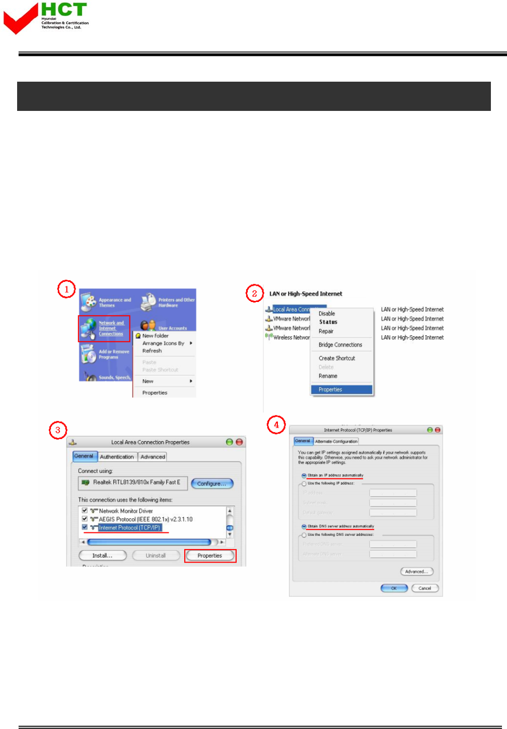
5.1 IP Address verification and Explorer setting
5.1.1 IP Address verification and Explorer setting
(1) Start->Control Panel->Network Connections
(2) Double-click Local Area Connections at LAN or High Speed internet
(3) Click Internet Protocol (TCP/IP) at General tap and click Properties.
(4) Apply automatic IP address assignment at local connection
Report No. : HCT-R07-013 25/33
FCC ID : U88GSTR1930DT-SPR
HYUNDAI CALIBRATION & CERTIFICATION TECHNOLOGIES CO., LTD.
SAN 136-1, AMI-RI, BUBAL-EUP, ICHEON-SI, KYOUNGKI-DO, 467-701, KOREA
TEL:+82 31 639 8517 FAX:+82 31 639 8525 www.hct.co.kr
26
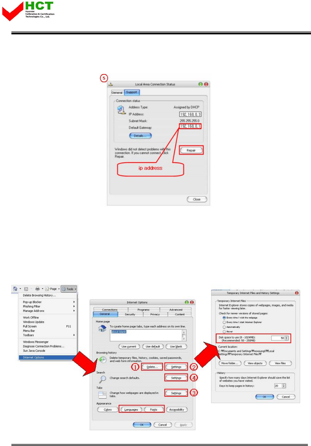
(5) Verify assigned IP address at local connection.
(Unless IP address is not assigned, please click repair.)
5.1.2 Explorer option setting
- Proceed step by step as indicated in below. All files and records should be removed.
- Set up mode will be displayed after (2) click.
- Please proceed along following set up mode screen shot.
Report No. : HCT-R07-013 26/33
FCC ID : U88GSTR1930DT-SPR
HYUNDAI CALIBRATION & CERTIFICATION TECHNOLOGIES CO., LTD.
SAN 136-1, AMI-RI, BUBAL-EUP, ICHEON-SI, KYOUNGKI-DO, 467-701, KOREA
TEL:+82 31 639 8517 FAX:+82 31 639 8525 www.hct.co.kr
27
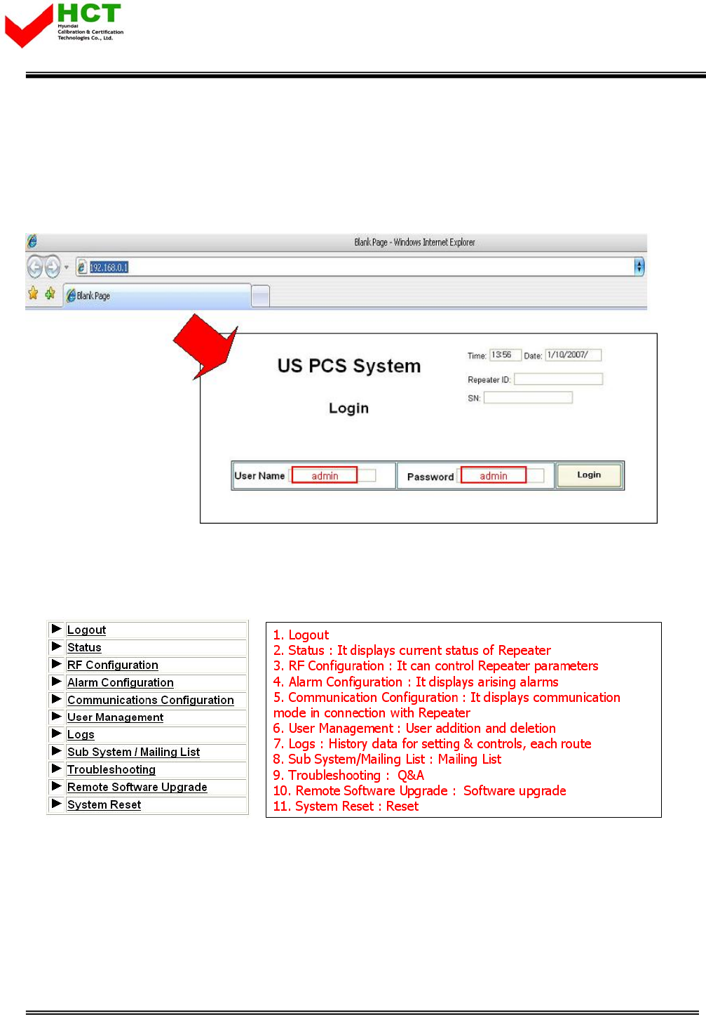
5.2 PCS Web UI
5.2.1 Web UI connection
- Input desirable IP address.
- Default Use Name and Password for Web UI is ‘admin’.
5.2.2 Link menu
- Following screen shot is located left-top side of main menu and those are linked to relative
window.
Report No. : HCT-R07-013 27/33
FCC ID : U88GSTR1930DT-SPR
HYUNDAI CALIBRATION & CERTIFICATION TECHNOLOGIES CO., LTD.
SAN 136-1, AMI-RI, BUBAL-EUP, ICHEON-SI, KYOUNGKI-DO, 467-701, KOREA
TEL:+82 31 639 8517 FAX:+82 31 639 8525 www.hct.co.kr
28
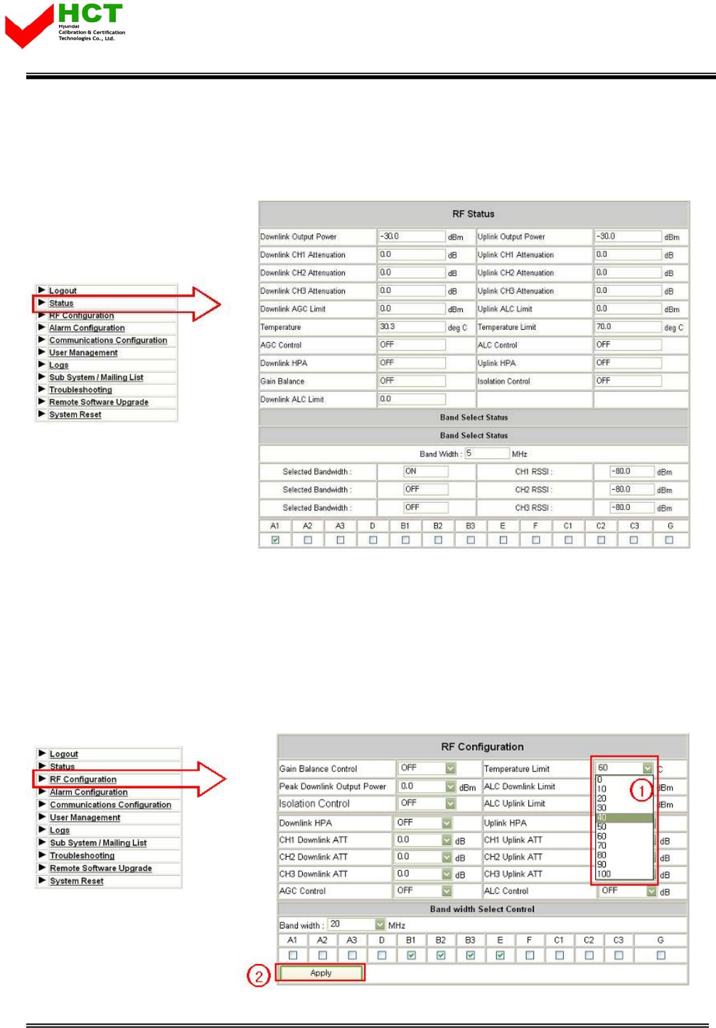
5.3 Web UI control
5.3.1 Status
- Currently setting level check at this menu tap.
5.3.2 RF Configuration
- Setting level can be changed at this menu tap.
- (1) Level change
- (2) Click Apply button
Report No. : HCT-R07-013 28/33
FCC ID : U88GSTR1930DT-SPR
HYUNDAI CALIBRATION & CERTIFICATION TECHNOLOGIES CO., LTD.
SAN 136-1, AMI-RI, BUBAL-EUP, ICHEON-SI, KYOUNGKI-DO, 467-701, KOREA
TEL:+82 31 639 8517 FAX:+82 31 639 8525 www.hct.co.kr
29
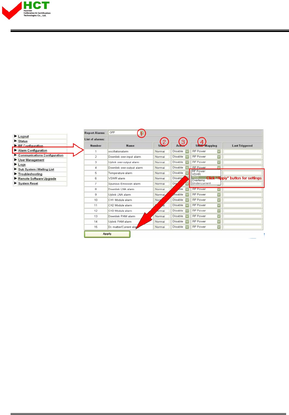
5.3.3 Alarm Configuration
- (1) On/Off function for entire alarm report
- (2) Alarm status
- (3) On/Off function for individual alarm category
- (4) Alarm SNMP Mapping
- User may set and change its level per it field condition and click apply button.
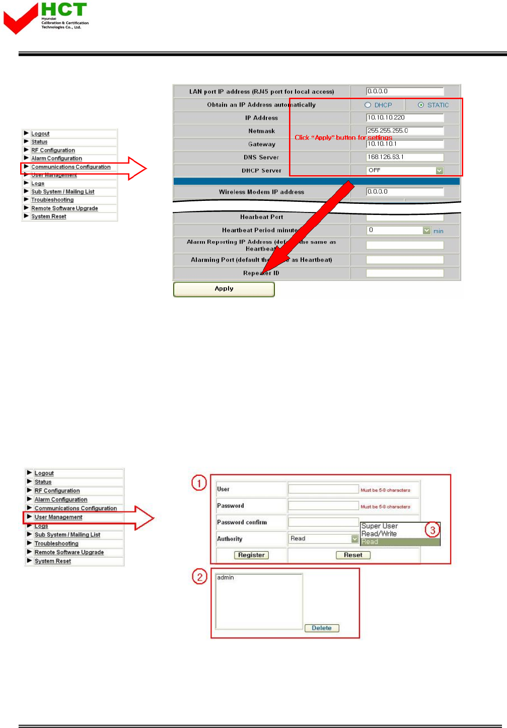
5.3.4 Communication Configuration
- This provides all necessary information related to network
- To provide relative information about DHCP and modem
Report No. : HCT-R07-013 29/33
FCC ID : U88GSTR1930DT-SPR
HYUNDAI CALIBRATION & CERTIFICATION TECHNOLOGIES CO., LTD.
SAN 136-1, AMI-RI, BUBAL-EUP, ICHEON-SI, KYOUNGKI-DO, 467-701, KOREA
TEL:+82 31 639 8517 FAX:+82 31 639 8525 www.hct.co.kr
30
5.3.5 User Management
- Add and Remove user, Assigning accessibility
- (1) User Registration: Click Register after input required information
- (2) User Removal: Click Delete upon click of user name you wish to remove.
- (3) Super User: Accessible to all kinds of information path
Read/Write: Accessible to all kinds of information path except for User management path.
Read: Checking status only. No control
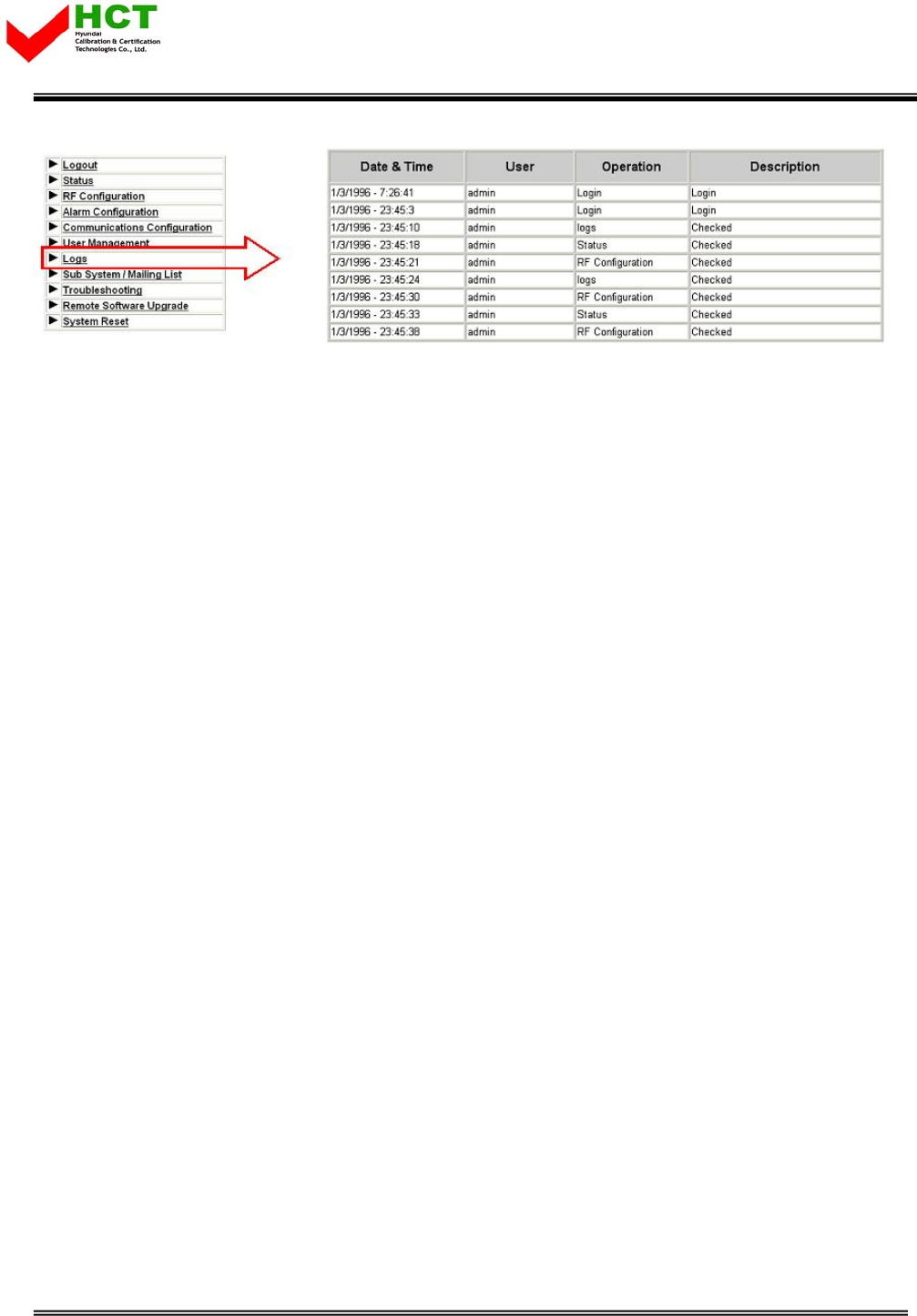
5.3.6 Logs
- All users’ access record will be saved as a log.
Report No. : HCT-R07-013 30/33
FCC ID : U88GSTR1930DT-SPR
HYUNDAI CALIBRATION & CERTIFICATION TECHNOLOGIES CO., LTD.
SAN 136-1, AMI-RI, BUBAL-EUP, ICHEON-SI, KYOUNGKI-DO, 467-701, KOREA
TEL:+82 31 639 8517 FAX:+82 31 639 8525 www.hct.co.kr
31
Report No. : HCT-R07-013 31/33
FCC ID : U88GSTR1930DT-SPR
HYUNDAI CALIBRATION & CERTIFICATION TECHNOLOGIES CO., LTD.
SAN 136-1, AMI-RI, BUBAL-EUP, ICHEON-SI, KYOUNGKI-DO, 467-701, KOREA
TEL:+82 31 639 8517 FAX:+82 31 639 8525 www.hct.co.kr
32
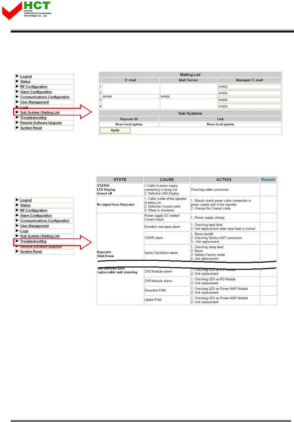
5.3.7 Sub System/Mailing List
- Set up e-mail address the place you wish to receive alarm.
5.3.8 Troubleshooting
Following is a trouble shooting table, which is frequently occurred to repeater and treatment
method.
Report No. : HCT-R07-013 32/33
FCC ID : U88GSTR1930DT-SPR
HYUNDAI CALIBRATION & CERTIFICATION TECHNOLOGIES CO., LTD.
SAN 136-1, AMI-RI, BUBAL-EUP, ICHEON-SI, KYOUNGKI-DO, 467-701, KOREA
TEL:+82 31 639 8517 FAX:+82 31 639 8525 www.hct.co.kr
33
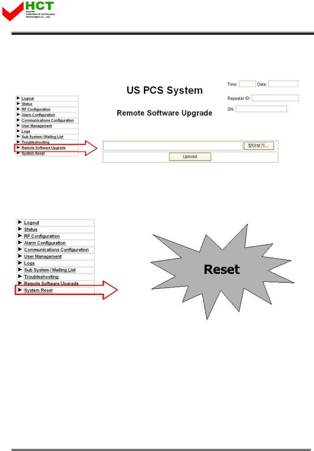
5.3.9 Remote Software Upgrade
- Upload repeater operation program.
5.3.10 System Reset
- Reset repeater.
Report No. : HCT-R07-013 33/33