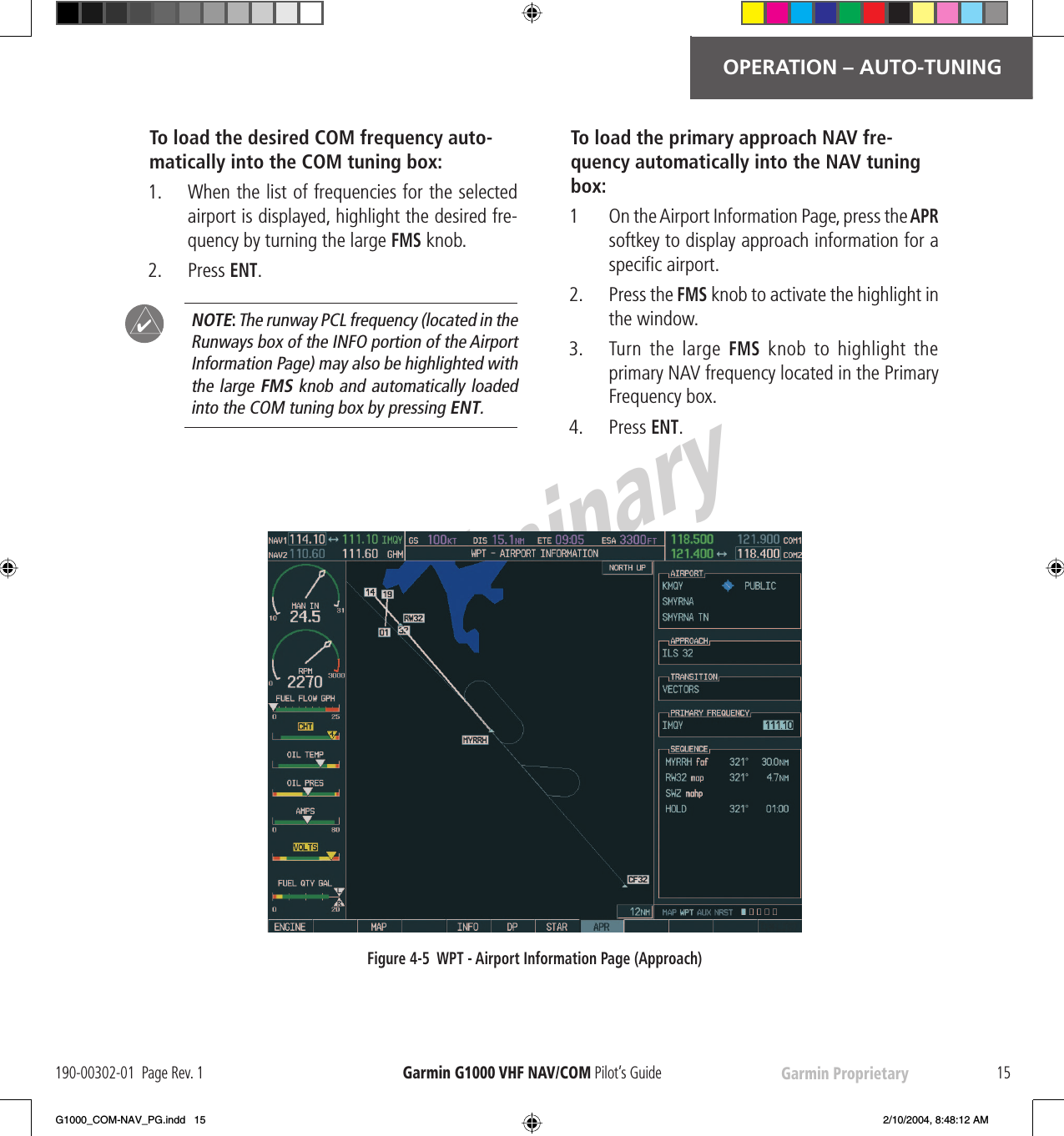
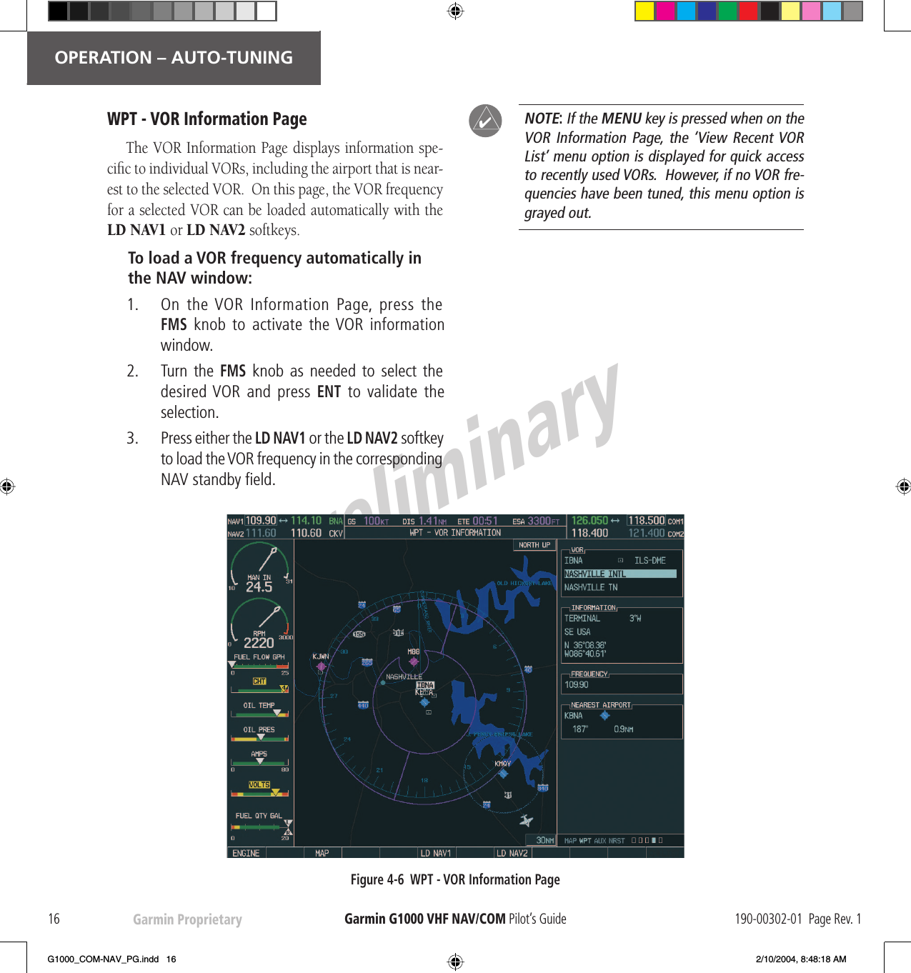
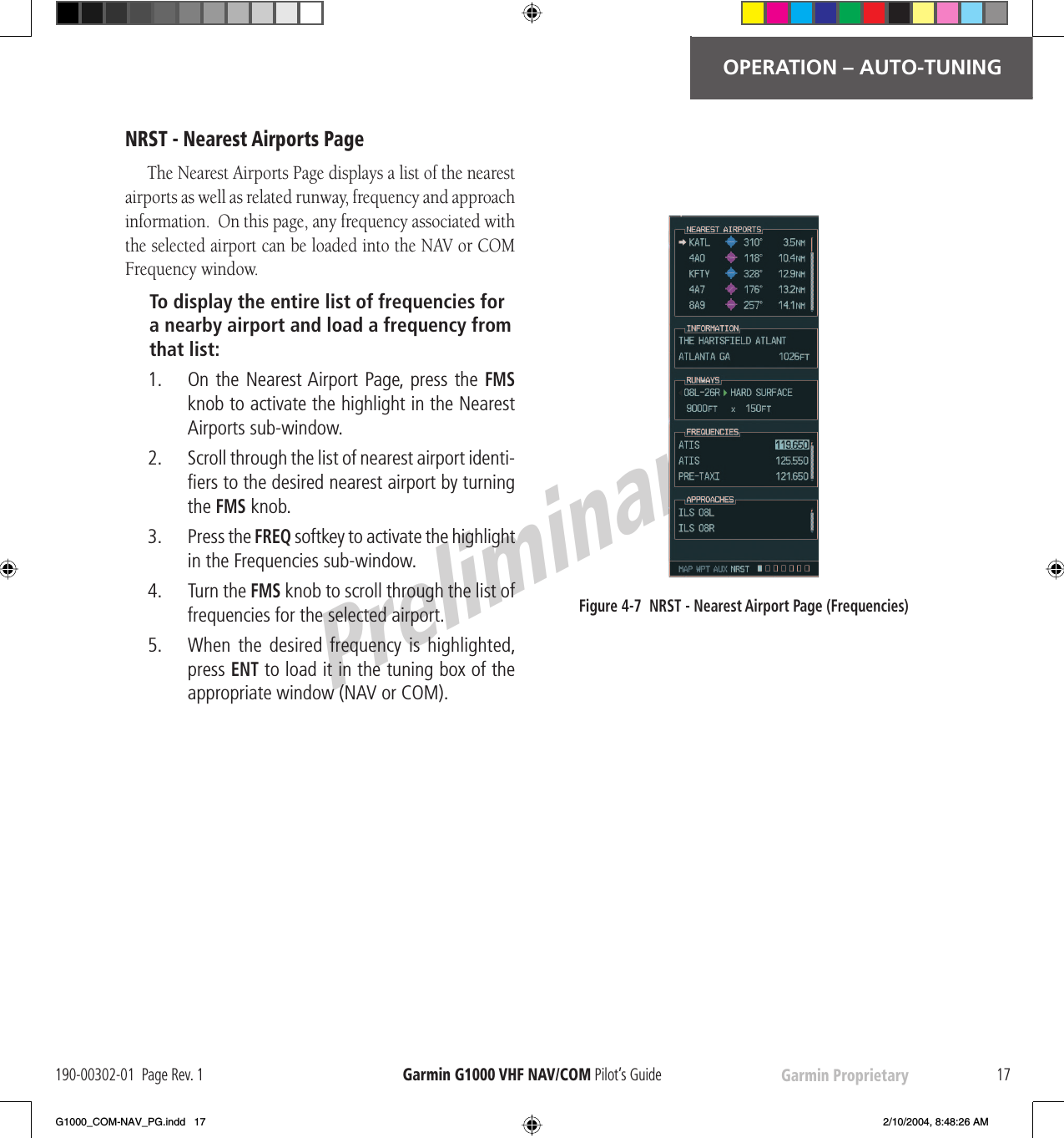
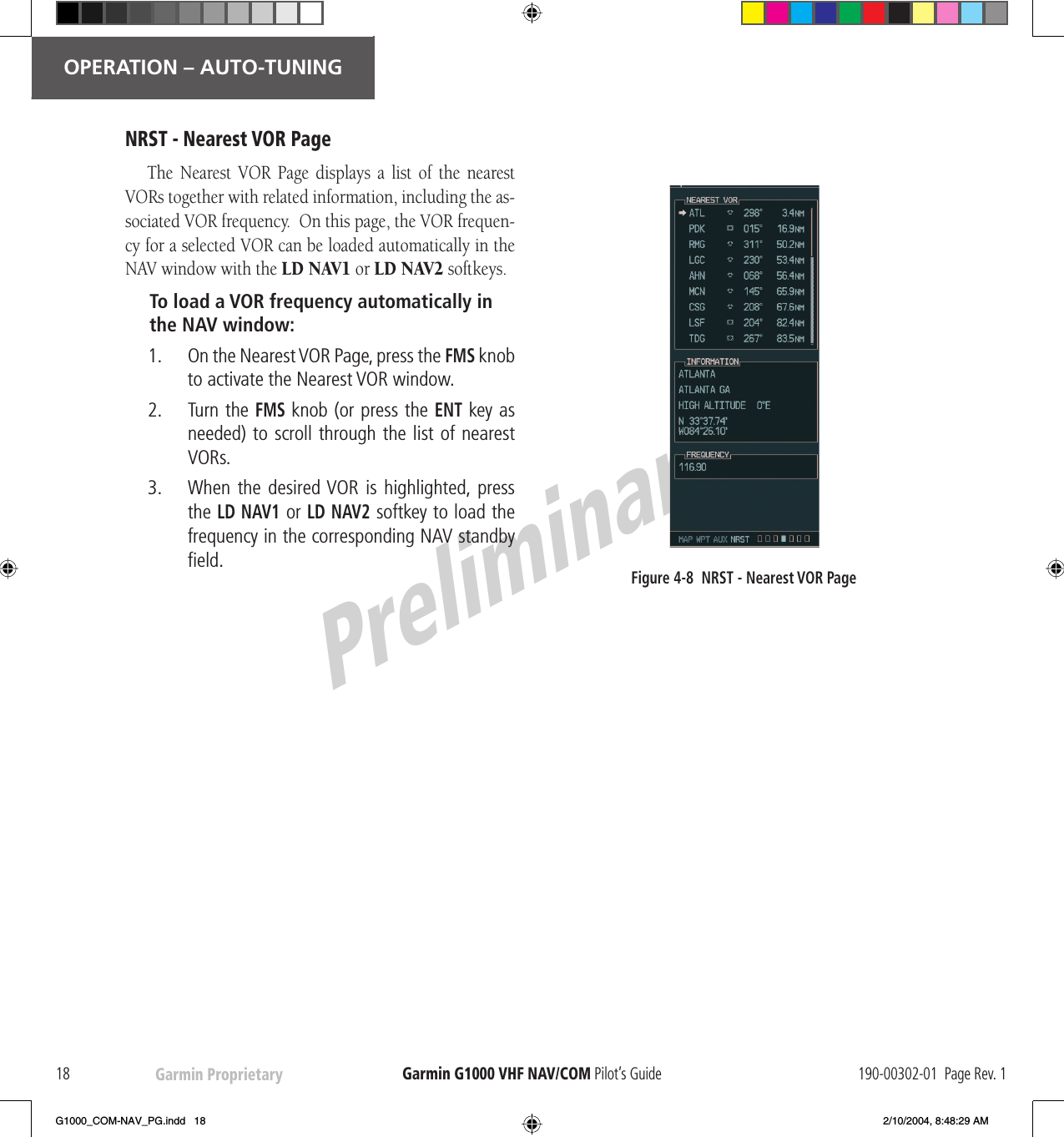
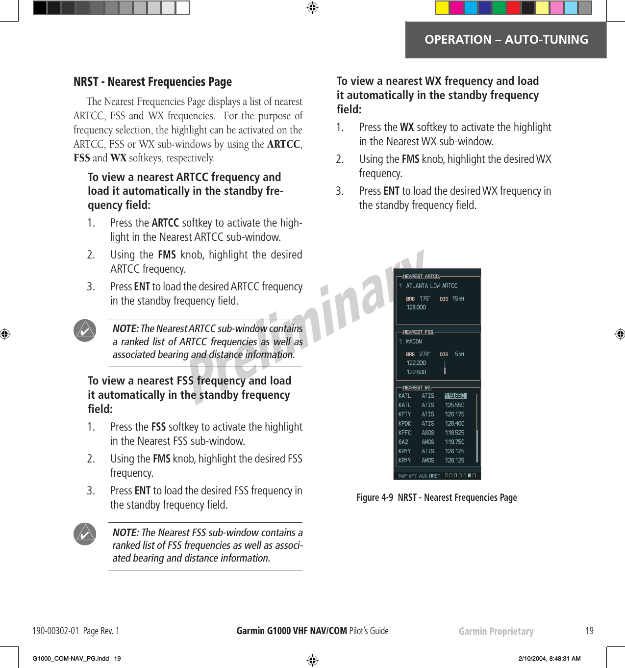
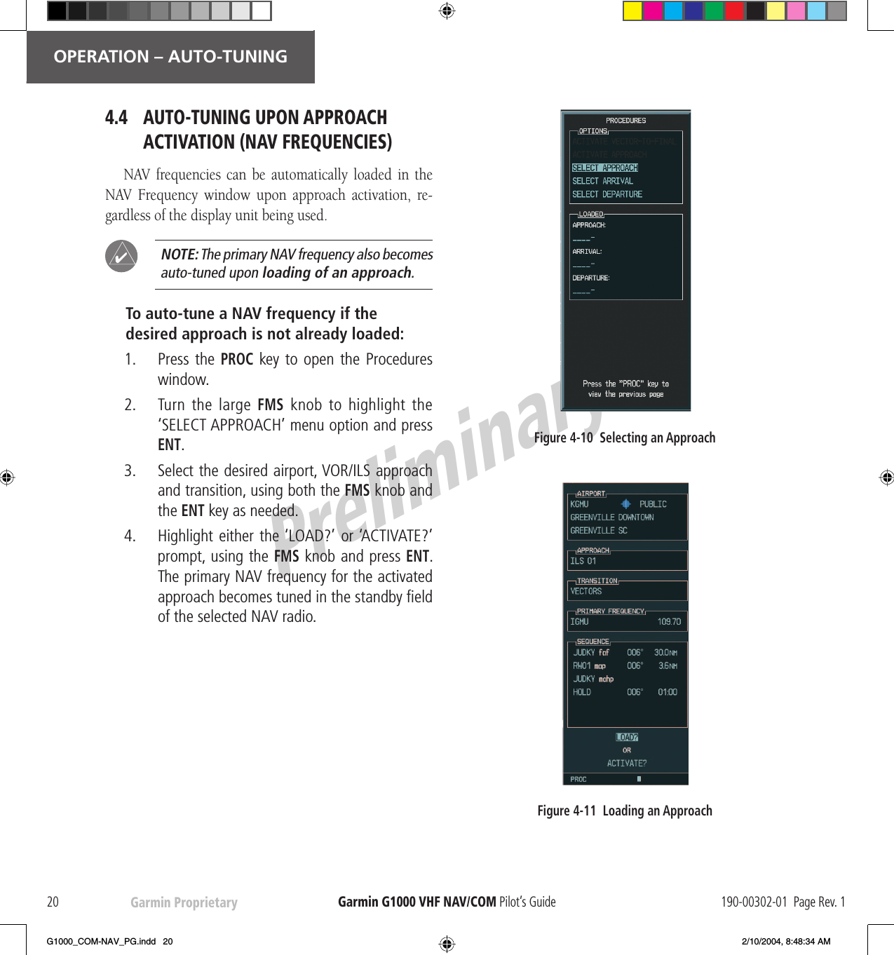
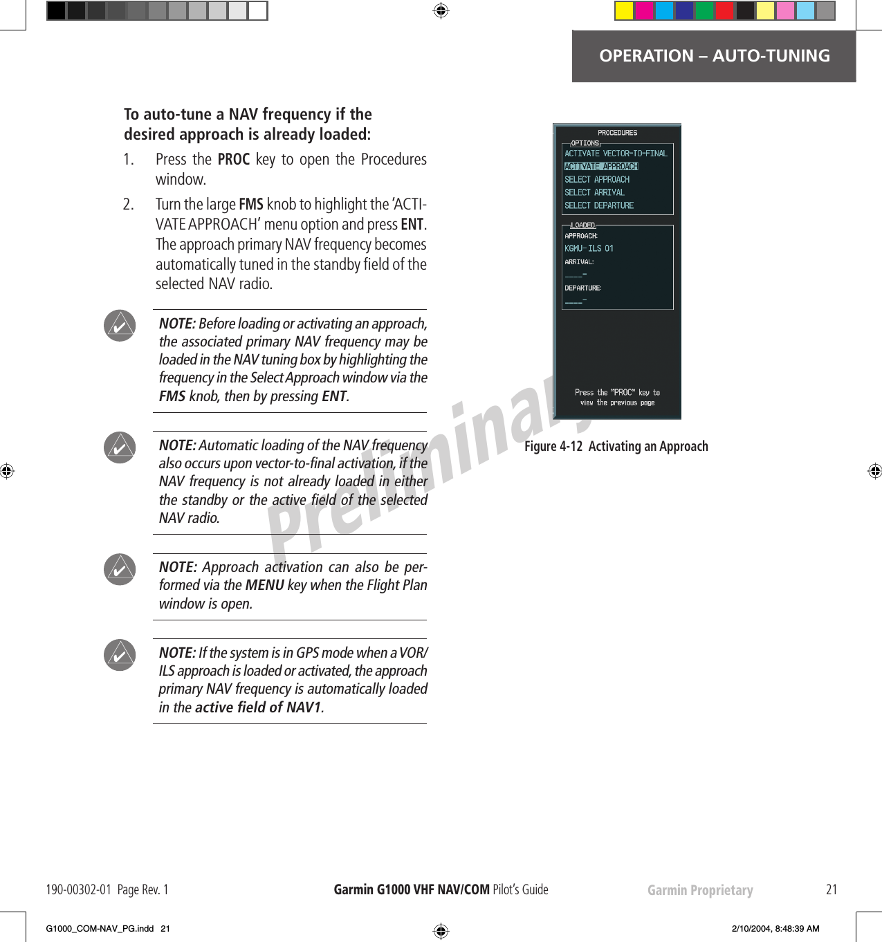
Garmin 0058501 AIRBORNE COMMUNICATIONS TRANSCEIVER User Manual G1000 COM NAV PG indd

Garmin International Inc AIRBORNE COMMUNICATIONS TRANSCEIVER G1000 COM NAV PG indd

PILOTS GUIDE

Garmin G1000™  VHF NAV/COMPilot’s GuideDRAFTGarmin ProprietaryG1000_COM-NAV_PG.indd   a 2/10/2004, 8:46:12 AM
PreliminaryGarmin Proprietary Garmin G1000  VHF NAV/COM Pilot’s GuideG1000_COM-NAV_PG.indd   b 2/10/2004, 8:46:47 AM
PreliminaryGarmin Proprietary iGarmin G1000  VHF NAV/COM Pilot’s Guide190-00302-01  Page Rev. 1    Copyright© 2004 Garmin Ltd. or its subsidiaries.  All rights reserved.This manual refl ects the operation of Main System Software version TBD or above. Some differences in operation may be observed when comparing the information in this manual to earlier software versions.Garmin International, Inc., 1200 East 151st Street, Olathe, Kansas 66062, U.S.A.Tel: 913/397.8200     Fax: 913/397.8282Garmin AT, Inc., 2345 Turner Road SE, Salem, OR 97302, U.S.A.Tel: 503/391.3411     Fax 503/364.2138Garmin (Europe) Ltd., Unit 5, The Quadrangle, Abbey Park Industrial Estate, Romsey, Hampshire S051 9DL, U.K.Tel: 44/1794.519944     Fax: 44/1794.519222Garmin Corporation, No. 68, Jangshu 2nd Road, Shijr, Taipei County, TaiwanTel: 886/02.2642.9199     Fax: 886/02.2642.9099Web Site Address: www.garmin.comExcept as expressly provided herein, no part of this manual may be reproduced, copied, transmitted, disseminated, downloaded or stored in any storage me di um, for any purpose without the express written permission of Garmin. Gar-min hereby grants permission to download a single copy of this manual and of any revision to this manual onto a hard drive or other electronic storage medium to be viewed for personal use, provided that such electronic or printed copy of this manual or revision must contain the complete text of this copyright notice and provided further that any unauthor-ized commercial distribution of this manual or any revision hereto is strictly prohibited.Information in this document is subject to change without notice. Garmin reserves the right to change or improve their products and to make changes in the content of this material without obligation to notify any person or organization of such changes or improvements.Garmin® is a  registered  trademark of Garmin Ltd. or its subsidiaries and may not be used without the express permission of Garmin.January 2004    Printed in the U.S.A.iCOPYRIGHTG1000_COM-NAV_PG.indd   i 2/10/2004, 8:46:47 AM
PreliminaryGarmin Proprietaryii Garmin G1000  VHF NAV/COM Pilot’s Guide 190-00302-01  Page Rev. 1    Revision Date of  Revision Affected Pages Description InsertedBy/Date1 01/12/04 All Preliminary Release for FAARECORD OF REVISIONSG1000_COM-NAV_PG.indd   ii 2/10/2004, 8:46:48 AM
PreliminaryGarmin Proprietary iiiGarmin G1000  VHF NAV/COM Pilot’s Guide190-00302-01  Page Rev. 1  LIST OF EFFECTIVE PAGESPage Number  Revision Page Number  RevisionCoveri-2411G1000_COM-NAV_PG.indd   iii 2/10/2004, 8:46:48 AM
PreliminaryGarmin Proprietaryiv Garmin G1000  VHF NAV/COM Pilot’s Guide 190-00302-01  Page Rev. 1   TABLE OF CONTENTSCopyright iRecord of Revisions  iiList of Effective Pages  iiiTable of Contents  ivList of Figures  vAbbreviations & Acronyms  viSection 1: Interface Description  11.1 Overview............................................................... 11.2  Windows and Fields ............................................. 21.3 Frequency Status ................................................. 21.4 Color Code ............................................................ 31.5 Tuning Box ............................................................ 31.6 Frequency Toggle Arrow ..................................... 31.7 Radio Status Indications ..................................... 31.8 Controls................................................................. 4Section 2: COM Frequency Window  52.1 Overview............................................................... 52.2 Volume .................................................................. 52.3 Automatic Squelch............................................... 52.4  Switching The Tuning Box Between COM Radios ................................................................... 52.5  Manually Tuning a COM Frequency .................... 62.6  Toggling COM Frequencies.................................. 62.7 Selecting COM RadioS ......................................... 62.8 Radio Status ......................................................... 72.9  Emergency Frequency (121.500 MHz)................. 7Quickly Tuning and Activating 121.500 MHz  72.10 Stuck Microphone................................................ 7Section 3: NAV Frequency Window  93.1 Overview............................................................... 93.2 Volume .................................................................. 93.3 Morse Code Identifi er.......................................... 93.4  Switching the Tuning Box Between NAV Radios ................................................................. 103.5  Manually Tuning a NAV Frequency................... 103.6  Toggling NAV Frequencies................................. 103.7  Selecting a NAV Radio ....................................... 11Section 4: Frequency Auto-tuning  134.1 Overview............................................................. 134.2  Auto-tuning on the PFD..................................... 134.3  Auto-tuning on the MFD ................................... 14WPT - Airport Information Page  14WPT - VOR Information Page  16NRST - Nearest Airports Page  17NRST - Nearest VOR Page  18NRST - Nearest Frequencies Page  194.4  Auto-Tuning Upon Approach Activation (NAV Frequencies).............................................. 20Index 23G1000_COM-NAV_PG.indd   iv 2/10/2004, 8:46:49 AM
PreliminaryGarmin Proprietary vGarmin G1000  VHF NAV/COM Pilot’s Guide190-00302-01  Page Rev. 1  LIST OF FIGURESFigure 1-1  G1000 VHF NAV/COM Interface (PFD) ........1Figure 1-2  Frequency Fields ........................................2Figure 1-3  Frequency Toggle Arrow and Tuning Box ...3Figure 1-4  NAV/COM Controls .....................................4Figure 2-1  Overriding Automatic Squelch ...................5Figure 2-2  Switching COM Radios...............................5Figure 2-3  Toggling COM Frequencies.........................6Figure 2-4  Selecting COM Radios................................6Figure 2-5  Split COM ...................................................6Figure 2-6  Radio Status Indications ............................7Figure 2-7  Communication Failure ..............................7Figure 2-8  Quickly Tuning 121.500 MHz ......................7Figure 2-9  Stuck MIC Alert ..........................................7Figure 3-1  ID Indication...............................................9Figure 3-2  Morse Code Identifi er Audio......................9Figure 3-3  Switching NAV Radios..............................10Figure 3-4  Toggling NAV Frequencies........................10Figure 3-5  Selecting NAV Radios...............................11Figure 4-1  Loading Frequencies ................................13Figure 4-2  Nearest Airports Window (PFD) ...............13Figure 4-3  MFD Page Group Icon ..............................14Figure 4-4  WPT - Airport Information Page (Info) .....14Figure 4-5  WPT - Airport Information Page (Approach)...............................................15Figure 4-6  WPT - VOR Information Page....................16Figure 4-7  NRST - Nearest Airport Page (Frequencies) ...........................................17Figure 4-8  NRST - Nearest VOR Page.........................18Figure 4-9  NRST - Nearest Frequencies Page ............19Figure 4-10  Selecting an Approach ...........................20Figure 4-11  Loading an Approach .............................20Figure 4-12  Activating an Approach..........................21G1000_COM-NAV_PG.indd   v 2/10/2004, 8:46:49 AM
PreliminaryGarmin Proprietaryvi Garmin G1000  VHF NAV/COM Pilot’s Guide 190-00302-01  Page Rev. 1   ABBREVIATIONS & ACRONYMSAPR ApproachARTCC  Air Route Traffi c Control CenterAUX Auxiliary CDI  Course Deviation IndicatorCDU Control Display UnitCOM Communication (radio)ENT EnterFMS  Flight Management SystemFPL Flight planFREQ FrequencyFSS  Flight Service StationGPS  Global Positioning SystemHSI Horizontal Situation IndicatorHz HertzID  Morse code identifi erILS  Instrument Landing SystemkHz KilohertzLD NAV1  Load NAV1LD NAV2  Load NAV2MFD Multi Function DisplayMHz MegahertzMIC MicrophoneMSA Minimum Safe AltitudeNAV Navigation (radio)NRST NearestPFD  Primary Flight DisplayPROC Procedure(s)PTT Push-to-TalkRX Receive    SQ  Squelch  STBY  StandbyTIS  Traffi c Information ServiceTX TransmitVFR  Visual Flight RulesVHF  Very High FrequencyVOL VolumeVOR  VHF Omnidirectional RangeWX WeatherAbbreviation or Acronym  Defi nition Abbreviation or Acronym  Defi nitionG1000_COM-NAV_PG.indd   vi 2/10/2004, 8:46:50 AM
PreliminaryGarmin Proprietary 1INTERFACE DESCRIPTION190-00302-01  Page Rev. 1    Garmin G1000  VHF NAV/COM Pilot’s GuideSection 1:  Interface Description1.1 OVERVIEWOn both the  PFD and the  MFD, the G1000  VHF NAV/COM interface occupies the top portion of the panel.  As shown in Figure 1-1, the NAV-related controls, windows and fi elds are located on the left side, whereas the COM-related controls, windows and fi elds are located on the right side.This section provides information on the following aspects of the G1000  VHF NAV/COM interface:•   Windows and fi elds•    Frequency status•     Color code•    Tuning box•    Frequency Toggle Arrow•    Radio status indications•    ControlsNAV Controls COM Controls NAV Frequency Window  COM Frequency WindowFigure 1-1  G1000  VHF NAV/COM Interface ( PFD)G1000_COM-NAV_PG.indd   1 2/10/2004, 8:46:51 AM
PreliminaryGarmin Proprietary2INTERFACE DESCRIPTIONGarmin G1000  VHF NAV/COM Pilot’s Guide 190-00302-01  Page Rev. 11.2 WINDOWS AND FIELDSOn both the  PFD and the  MFD, the NAV and COM Frequency windows are located at the top of the display on either side of the  Navigation Status bar.•   The NAV Frequency window is displayed to the left of the  Navigation Status bar.•   The COM Frequency window is displayed to the right of the  Navigation Status bar.Each radio frequency sub-window is composed of two (2) fi elds, a  standby fi eld and an  active fi eld.•   In the NAV Frequency window, the  active fre-quency fi eld is located on the right side, while the  standby frequency fi eld is located on the left side.•   In the COM Frequency window, the  active frequency fi eld is located on the left side, while the  standby frequency fi eld is located on the right side.1.3 FREQUENCY STATUSFrequencies on the  VHF NAV/COM interface can ei-ther be standby, active or selected.•   Standby – indicates that the frequency is located in the  standby fi eld of the associated radio.•   Active – indicates that the frequency is located in the  active fi eld of the associated radio.•    Selected – indicated that the frequency is active and that the associated radio is selected:– on the  HSI (NAV frequencies)– on the GMA 1347  audio panel (COM frequen-cies) - COM MIC.Standby NAVFrequency FieldActive NAVFrequency FieldActive COMFrequency FieldStandby COMFrequency FieldFigure 1-2  Frequency FieldsSelected NAVFrequency Selected COMFrequencyNavigation Status BarTuning BoxG1000_COM-NAV_PG.indd   2 2/10/2004, 8:47:21 AM
PreliminaryGarmin Proprietary 3OPERATION – COM190-00302-01  Page Rev. 1    Garmin G1000  VHF NAV/COM Pilot’s Guide1.4  COLOR CODEFrequencies located in the  active fi eld are displayed in either   green or   white.•   An  active frequency that is displayed in   green indicates that the corresponding radio is selected (i.e., in use).•   An  active frequency that is displayed in   white indicates that the corresponding radio is not selected.Frequencies located in the  standby fi eld are displayed in either   white or  gray.•   The  standby frequency that appears in the tuning box is displayed in   white.•   The  standby frequency that is not in the tuning box is displayed in  gray.NOTE: In GPS mode, both active NAV frequencies are displayed in   white.NOTE: In split COM mode, both active COM frequencies are displayed in   green.1.5 TUNING BOXOn both the  PFD and the  MFD, a  cyan tuning box ap-pears over the  standby frequency fi eld and can be moved from one  standby frequency fi eld to another for the pur-pose of tuning or radio selection.In both the COM and NAV windows, the frequency toggle arrow appears next to the tuning box, between the active and standby frequencies. Frequency Toggle Arrow Frequency Tuning BoxFigure 1-3   Frequency Toggle Arrow and Tuning Box1.6  FREQUENCY TOGGLE ARROWA  Frequency Toggle Arrow appears between the two frequencies of the radio sub-window on which the fre-quency tuning box is located.  Pressing the dual COM or  NAV knob toggles both the frequency tuning box and the  Frequency Toggle Arrow between the radios.NOTE: If the frequency tuning box is on a selected COM sub-window when a signal is received or transmitted for this radio, the  Frequency Toggle Arrow is replaced by an  RX or a  TX indication, respectively.NOTE: When the desired frequency is entered in the tuning box, it becomes a  standby frequency.  Pressing the  Frequency Toggle key places this  standby frequency into the  active fi eld, and vice versa.1.7 RADIO STATUS INDICATIONS•    RX – When a signal is received on a COM radio, a   white  RX indication appears to the right of the corresponding COM frequency for the duration of the signal reception.•    TX – When a microphone is keyed, a   white  TX indication appears to the right of the correspond-ing COM frequency for the duration of the signal transmission.•    ID – When the  VOL/PUSH  ID knob is pressed, a   white  ID indication appears to the left of the NAV frequency on the selected NAV sub-window and the  Morse code identifi er audio for the selected  VOR frequency can be heard if the corresponding NAV radio is selected on the  audio panel.!!!!G1000_COM-NAV_PG.indd   3 2/10/2004, 8:47:24 AM
PreliminaryGarmin Proprietary4OPERATION – COMGarmin G1000  VHF NAV/COM Pilot’s Guide 190-00302-01  Page Rev. 11.8  CONTROLSThe NAV Frequency window is controlled by knobs and keys located to the left side of the display, while the COM Frequency window is controlled by knobs and keys located to the right side of the display.The controls associated with the NAV window are:•   A  VOL/PUSH  ID knob –  Turn to adjust the NAV radio  volume level.–  Press to turn the  Morse code identifi er ON and OFF.•   A  Frequency Toggle key–  Press to toggle the NAV frequencies between the active and  standby fi elds.•   A dual  NAV knob –  Turn to tune a NAV frequency in the NAV tuning box (large knob for MHz; small knob for kHz).–  Press to toggle the NAV tuning box between the NAV radios.The controls associated with the COM window are the following ones:•   A  VOL/PUSH SQ knob –  Turn to adjust the COM radio  volume level.–  Press to turn squelch ON and OFF.•   A  Frequency Toggle key–  Press to toggle the COM frequencies between the active and  standby fi elds.•   A dual  COM knob –  Turn to tune a COM frequency in the COM tuning box (large knob for MHz; small knob for kHz).–  Press to toggle the COM tuning box between the COM radios.Figure 1-4  NAV/COM  ControlsFrequency Toggle KeyDual NAV Knob Dual COM Knob VOL/PUSH  ID Knob  VOL/PUSH SQ KnobNAV  Controls COM  Controls•  Tur n to tune in desired frequencies.•  Press to switch radios.G1000_COM-NAV_PG.indd   4 2/10/2004, 8:47:25 AM
PreliminaryGarmin Proprietary 5OPERATION – COM190-00302-01  Page Rev. 1    Garmin G1000  VHF NAV/COM Pilot’s GuideSection 2: COM Frequency Window2.1 OVERVIEWThe G1000 COM radios operate in the  aviation fre-quency band of 118.000 to 136.990 MHz with either 25 kHz or 8.33 kHz channel spacing.NOTE: COM channel spacing can be confi gured through the  MFD, in the System Setup Page of the  AUX Page group.The Communications Frequency window is located to the right of the  Navigation Status bar, provides the control and display of dual   VHF Radio Communication Transceivers (  COM1 and   COM2) and displays the follow-ing information:•     COM1 and   COM2  active and standby frequencies•    Color-coded indication of the  selected COM  radio•   Indication of signal reception and transmissionNOTE:  In split COM mode, both  COM1 and  COM2 active frequencies are selected and thus displayed  in    green.2.2 VOLUMEVolume level for the COM radios can be adjusted using the  VOL/PUSH SQ knob (top knob on the right side of the display) located above the COM  Frequency Toggle key.  Turning the  VOL/PUSH SQ knob clockwise increases  volume level, while turning this knob counter-clockwise decreases  volume level.2.3 AUTOMATIC SQUELCH Automatic squelch provides maximum sensitivity to weaker signals while canceling most localized noise sources.    Automatic squelch can be disabled for a COM radio by pressing the  COM  knob to select the desired COM sub-window, then by pressing the  VOL/PUSH SQ knob.When automatic squelch is disabled for a COM radio, COM audio remains continuously open and an  RX indi-cation appears between the active and standby frequency fi elds of this radio.Figure 2-1  Overriding Automatic SquelchNOTE: Pressing the VOL/PUSH SQ knob when automatic squelch is disabled reactivates the automatic squelch function.2.4 SWITCHING THE TUNING BOX BETWEEN COM RADIOSPressing the   COM knob toggles the frequency tuning box between the   COM1 and  COM2 fi elds.NOTE: When a different COM MIC is selected on the  audio panel, the frequency tuning box also moves on both the   PFD and  MFD. Figure 2-2  Switching COM RadiosPushing the  COM knob switches the tuning box from one COM radio to the other.!!!!G1000_COM-NAV_PG.indd   5 2/10/2004, 8:47:36 AM
PreliminaryGarmin Proprietary6OPERATION – NAVGarmin G1000  VHF NAV/COM Pilot’s Guide 190-00302-01  Page Rev. 12.5 MANUALLY TUNING A COM FREQUENCYCOM frequency  manual tuning is performed by using the dual  COM knob.•   The MHz (left) portion of the frequency can be tuned by turning the large  COM knob.•   The  kHz (right) portion of the frequency can be tuned by turning the small  COM knob.Turning either knob clockwise increases the tuned frequency.  Conversely, turning either knob counterclock-wise decreases the tuned frequency.  The tuned frequency is placed in the  standby frequency fi eld of the COM Fre-quency window.NOTE: Only when tuning frequencies manually can the  standby frequency fi eld for a COM radio be tuned to the same frequency as that located in the  active fi eld for the same COM radio.2.6   TOGGLING COM FREQUENCIESPressing the COM  Frequency Toggle key toggles the COM frequencies between the  active and standby fi elds of the COM radio on which the Frequency Toggle Arrow is located.2.7 SELECTING COM RADIOSTo be selected, a COM frequency must be placed in the   active fi eld and the corresponding COM radio must be selected on the GMA 1347  audio panel.  When se-lected, the COM frequency of the selected COM radio is displayed in   green.NOTE: A COM radio can only be selected through the GMA 1347  audio panel (COM MIC key).  Please, see Garmin GMA 1347 Pilot’s Guide for details.Figure 2-4   Selecting COM RadiosCOM radio selection is performed via the  audio panel. Top portion of the GMA 1347  audio  panelNOTE: The  selected COM frequency is always displayed  in    green.NOTE: In split COM mode, both  COM1 and  COM2 radios are selected; the associated active frequencies are thus displayed in   green in the COM Frequency window.Figure 2-5  Split COM!!!!Figure 2-3   Toggling COM FrequenciesPressing the COM  Frequency Toggle key toggles the COM frequencies.G1000_COM-NAV_PG.indd   6 2/10/2004, 8:47:40 AM
PreliminaryGarmin Proprietary 7OPERATION – NAV190-00302-01  Page Rev. 1    Garmin G1000  VHF NAV/COM Pilot’s Guide2.8 RADIO STATUSWhen a microphone is keyed, a   white  TX indication appears between the active COM frequency and the standby COM frequency to indicate that a transmission is in progress.  The  TX indication disappears once COM transmission is completed.When a COM signal is received, a   white  RX indication appears to the right of the active COM frequency to indi-cate that a COM signal reception is in progress.  The  RX indication disappears once COM signal reception is over.Figure 2-6  Radio Status IndicationsNOTE: If a signal is transmitted or received on a COM radio for which frequency toggling is enabled (i.e., on which the tuning box is located), the  Frequency Toggle Arrow disappears and is replaced by a  TX or an  RX indication, respec-tively.2.9  EMERGENCY FREQUENCY (121.500 MHZ)If data for the selected COM frequency is not received for a duration of one second, a communication failure is assumed by the system and the selected frequency is auto-matically changed to the emergency frequency (121.500 MHz).Figure 2-7  Communication FailureNOTE: In the event of a  dual CDU failure, the emergency frequency (121.500 MHz) automati-cally becomes available to the pilot through the pilot headset.Quickly Tuning and Activating 121.500 MHzPressing and holding the COM  Frequency Toggle key for approximately two (2) seconds automatically loads the emergency COM frequency (121.500 MHz) in the  active frequency fi eld of the COM radio for which frequency toggling is enabled.Figure 2-8   Quickly Tuning 121.500 MHz2.10 STUCK MICROPHONE If the  COM1 (or   COM2)  Remote Transfer key be-comes stuck, an alert appears on the   PFD to advise the crew of a stuck COM microphone.  Transmit capability is reset after 35 seconds of continuous transmitting.Figure 2-9   Stuck MIC Alert!!G1000_COM-NAV_PG.indd   7 2/10/2004, 8:47:49 AM
PreliminaryGarmin Proprietary8OPERATION – AUTO-TUNINGGarmin G1000  VHF NAV/COM Pilot’s Guide 190-00302-01  Page Rev. 1This page intentionally left blank.G1000_COM-NAV_PG.indd   8 2/10/2004, 8:47:52 AM
PreliminaryGarmin Proprietary 9OPERATION – AUTO-TUNING190-00302-01  Page Rev. 1    Garmin G1000  VHF NAV/COM Pilot’s GuideSection 3: NAV Frequency Window3.1 OVERVIEWThe G1000 NAV radios operate in the  aviation fre-quency band of 108.00 to 117.95 MHz, with 50 kHz channel spacing.The Navigation Frequency window is located to the left of the  Navigation Status bar, provides the control and display of dual   VOR/ILS receivers ( NAV1 and  NAV2) and displays the following information:•    NAV1 and  NAV2  active and standby frequencies•    NAV1 or  NAV2 identifi er indication (if the  active  NAV frequency is a valid frequency and its Morse code identifi er signal is received by the system).•     Color code indication of the  selected NAV receiver•   Indication of the  Morse code identifi er fi lter status3.2 VOLUMEVolume level for the NAV radios can be adjusted by using the  VOL/PUSH  ID knob (top knob on the left side of the display) located above the NAV  Frequency Toggle key.  Turning the  VOL/PUSH  ID knob clockwise increases  volume level, while turning this knob counter-clockwise decreases  volume level.3.3  MORSE CODE IDENTIFIERPressing the  VOL/PUSH  ID knob toggles the  Morse code identifi er fi lter ON and OFF for the active NAV fre-quency next to which the tuning box is located.  When the  Morse code identifi er fi lter is ON, an  ID indication appears to the left of the corresponding active NAV fre-quency.Figure 3-1   ID IndicationThe  Morse code identifi er fi lter is ON for the GHM  VOR.The  Morse code identifi er for an active NAV frequency can only be heard if the  Morse code identifi er  fi lter for the corresponding NAV radio is turned on (i.e., if the  ID indication appears next to the active NAV frequency) and if the corresponding NAV radio is selected on the GMA 1347  audio panel (i.e., the associated NAV radio  annun-ciator lights are illuminated).Here, since NAV2 is the only NAV radio selected on the  audio panel, only the  Morse code identifi er for the GHM  VOR can be heard.NAV portion of the GMA 1347  audio  panelFigure 3-2  Morse Code Identifi er AudioG1000_COM-NAV_PG.indd   9 2/10/2004, 8:47:53 AM
PreliminaryGarmin Proprietary10OPERATION – AUTO-TUNINGGarmin G1000  VHF NAV/COM Pilot’s Guide 190-00302-01  Page Rev. 13.4 SWITCHING THE TUNING BOX BETWEEN NAV RADIOSPressing the  dual  NAV  knob toggles the frequency tuning box between the  NAV1 and  NAV2 sub-windows.Pushing the  NAV knob switches the tuning box from one NAV radio to the other.Figure 3-3  Switching NAV RadiosNOTE: When a different NAV radio is selected on the HSI via the CDI key, the NAV frequency tuning box also moves on the   PFD and  MFD.  However, the NAV frequency tuning box does not move when GPS mode is selected. 3.5 MANUALLY TUNING A NAV FREQUENCYNAV frequency  manual tuning is performed by using the dual  NAV knob.•   The MHz (left) portion of the frequency can be tuned by turning the large  NAV knob.•   The  kHz (right) portion of the frequency can be tuned by turning the small  NAV knob.Turning either knob clockwise increases the tuned frequency.  Conversely, turning either knob counterclock-wise decreases the tuned frequency.  The tuned frequency is placed in the  standby frequency fi eld of the NAV Fre-quency window.NOTE: Only when tuning frequencies manually can the  standby frequency fi eld for a NAV radio be tuned to the same frequency as that located in the  active fi eld for the same NAV radio.3.6  TOGGLING NAV FREQUENCIESPressing the NAV  Frequency Toggle key toggles the NAV frequencies between the  active and standby fi elds of the NAV radio on which the Frequency Toggle Arrow is located.Figure 3-4   Toggling NAV FrequenciesPressing the NAV  Frequency Toggle key toggles the NAV frequencies.!!G1000_COM-NAV_PG.indd   10 2/10/2004, 8:47:56 AM
PreliminaryGarmin Proprietary 11OPERATION – NAV190-00302-01  Page Rev. 1    Garmin G1000  VHF NAV/COM Pilot’s Guide3.7  SELECTING A NAV RADIOTo be selected, a NAV frequency must be placed in the  active fi eld and the corresponding NAV radio must be displayed on the  HSI.  When selected, the active NAV fre-quency of the  selected NAV radio is displayed in   green.The desired NAV radio can be selected using the  CDI softkey.  The three  navigation modes that can be selected with the  CDI softkey are as follows:•   NAV1 – If NAV1 is selected as the NAV radio, a single   green arrow is displayed on the  HSI and the active NAV1 frequency is displayed in   green.•   NAV2 – If NAV2 is selected as the NAV radio, a double   green arrow is displayed on the  HSI and the active NAV2 frequency is displayed in   green.•    GPS Mode – If GPS mode is selected, a  single  magenta arrow appears on the  HSI and none of the active NAV frequencies are selected.NOTE: In GPS mode, all active NAV frequencies are displayed in   white.When a   VOR signal is received, the corresponding  VOR name identifi er is displayed to the right of the as-sociated active NAV frequency.Figure 3-5   Selecting NAV RadiosNAV radio selection is performed via the  CDI softkey.!G1000_COM-NAV_PG.indd   11 2/10/2004, 8:47:59 AM
PreliminaryGarmin Proprietary12OPERATION – NAVGarmin G1000  VHF NAV/COM Pilot’s Guide 190-00302-01  Page Rev. 1This page intentionally left blank.G1000_COM-NAV_PG.indd   12 2/10/2004, 8:48:04 AM
PreliminaryGarmin Proprietary 13OPERATION – AUTO-TUNING190-00302-01  Page Rev. 1    Garmin G1000  VHF NAV/COM Pilot’s GuideSection 4: Frequency Auto-tuning4.1 OVERVIEWThe G1000 system offers multiple auto-tuning capa-bilities that help to reduce cockpit workload.  The  PFD allows for the auto-tuning of COM frequencies associated with the nearest airports, while the  MFD provides auto-tuning of both COM and NAV frequencies from various pages.  In addition, regardless of the display, the pertinent  primary NAV frequency is entered systematically in the NAV window upon  approach loading or activation.In brief, frequencies can be automatically loaded in their respective frequency windows in the following ways:•   By using the ENT key when the frequency is highlighted on the appropriate page ( PFD and  MFD).•   By using the  LD NAV1 and  LD NAV2 softkeys when on the appropriate page ( MFD only).•   Upon loading or activating an approach ( PFD and  MFD).NOTE: Turn the  FMS knob to scroll through a list of frequencies.Turn the  FMS knob to scroll through a list of frequencies.Press ENT to load a highlighted frequency in the associated frequency window.Figure 4-1  Loading Frequencies4.2  AUTO-TUNING ON THE  PFDCOM frequencies for the nearest airports may be viewed and automatically loaded from the Nearest Airport window on the  PFD.To auto-tune a COM frequency for a nearby airport:1.     Press the NRST softkey to open the   Nearest Airports window, which displays the list of airport identifi ers and corresponding COM frequencies.2.     Turn either  FMS knob to highlight the desired COM frequency, and ensure that the COM frequency tuning box is on the desired COM sub-window.3.     Press the ENT key to load the COM frequency in the COM tuning box.NOTE: When the desired frequency is entered in the tuning box, it becomes a  standby frequency.  Pressing the  Frequency Toggle key places this  standby frequency into the  active fi eld.Figure 4-2    Nearest Airports Window ( PFD)Pressing the NRST softkey opens the   Nearest Airports window.!!G1000_COM-NAV_PG.indd   13 2/10/2004, 8:48:04 AM
PreliminaryGarmin Proprietary14OPERATION – AUTO-TUNINGGarmin G1000  VHF NAV/COM Pilot’s Guide 190-00302-01  Page Rev. 14.3  AUTO-TUNING ON THE  MFDFrequencies can be automatically loaded from the fol-lowing  MFD pages:•   WPT –  Airport Information•   WPT –   VOR Information•   NRST –   Nearest Airports•   NRST – Nearest  VOR•   NRST –  Nearest FrequenciesFigure 4-3    MFD Page Group IconNOTE: Upon any   VOR/ILS  approach activation, the appropriate NAV frequency is automatically loaded into the  standby fi eld of the  selected NAV radio, regardless of the current  MFD page that is displayed.WPT -  Airport Information PageThe  Airport Information Page displays runway infor-mation and a list of frequencies pertinent to the selected airport identifi er as well as departure, arrival and ap-proach information.To display the entire list of frequencies for a desired airport:1.     On  the  Airport  Information  Page, press  the  INFO softkey to display runway and frequency information for a specifi c airport.2.     Press the  FMS knob to activate the highlight in the window.3.     Select the  desired  airport  identifi er  by  turn-ing the  FMS knob and press ENT.  A list of all available frequencies for the selected airport appears.Figure 4-4  WPT -  Airport Information Page (Info)!G1000_COM-NAV_PG.indd   14 2/10/2004, 8:48:09 AM
PreliminaryGarmin Proprietary 15OPERATION – AUTO-TUNING190-00302-01  Page Rev. 1    Garmin G1000  VHF NAV/COM Pilot’s GuideTo load the desired COM frequency auto-matically into the COM tuning box:1.     When the list of frequencies for the selected airport is displayed, highlight the desired fre-quency by turning the large  FMS knob.2.     Press ENT.NOTE: The  runway PCL frequency (located in the Runways box of the INFO portion of the  Airport Information Page) may also be highlighted with the large  FMS knob and automatically loaded into the COM tuning box by pressing ENT.To load the primary approach NAV fre-quency automatically into the NAV tuning box:1      On the  Airport Information Page, press the  APR softkey to display approach information for a specifi c airport.2.     Press the  FMS knob to activate the highlight in the window.3.     Turn  the  large FMS knob to highlight the  primary NAV frequency located in the Primary Frequency box.4.     Press ENT.Figure 4-5  WPT -  Airport Information Page (Approach)!G1000_COM-NAV_PG.indd   15 2/10/2004, 8:48:12 AM
PreliminaryGarmin Proprietary16OPERATION – AUTO-TUNINGGarmin G1000  VHF NAV/COM Pilot’s Guide 190-00302-01  Page Rev. 1WPT -   VOR Information PageThe   VOR Information Page displays information spe-cifi c to individual VORs, including the airport that is near-est to the selected  VOR.  On this page, the  VOR frequency for a selected  VOR can be loaded automatically with the  LD NAV1 or  LD NAV2 softkeys.To load a  VOR frequency automatically in the NAV window:1.     On  the   VOR  Information  Page,  press  the  FMS knob to activate the  VOR information window.2.     Turn  the   FMS knob as needed to select the desired  VOR and press ENT to validate the selection.3.     Press either the  LD NAV1 or the  LD NAV2 softkey to load the  VOR frequency in the corresponding NAV  standby fi eld.NOTE: If the  MENU key is pressed when on the VOR Information Page, the ‘View Recent  VOR List’ menu option is displayed for quick access to  recently used VORs.  However, if no VOR fre-quencies have been tuned, this menu option is grayed out.Figure 4-6  WPT -   VOR Information Page!G1000_COM-NAV_PG.indd   16 2/10/2004, 8:48:18 AM
PreliminaryGarmin Proprietary 17OPERATION – AUTO-TUNING190-00302-01  Page Rev. 1    Garmin G1000  VHF NAV/COM Pilot’s GuideNRST -   Nearest Airports PageThe   Nearest Airports Page displays a list of the nearest airports as well as related runway, frequency and approach information.  On this page, any frequency associated with the selected airport can be loaded into the NAV or COM Frequency window.To display the entire list of frequencies for a nearby airport and load a frequency from that list:1.     On the  Nearest Airport Page,  press the  FMS knob to activate the highlight in the   Nearest Airports sub-window.2.     Scroll through the list of nearest airport identi-fi ers to the desired nearest airport by turning the  FMS knob.3.     Press the  FREQ softkey to activate the highlight in the Frequencies sub-window.4.     Turn the  FMS knob to scroll through the list of frequencies for the selected airport.5.     When  the  desired  frequency  is  highlighted, press ENT to load it in the tuning box of the appropriate window (NAV or COM).Figure 4-7  NRST - Nearest Airport Page (Frequencies)G1000_COM-NAV_PG.indd   17 2/10/2004, 8:48:26 AM
PreliminaryGarmin Proprietary18OPERATION – AUTO-TUNINGGarmin G1000  VHF NAV/COM Pilot’s Guide 190-00302-01  Page Rev. 1NRST - Nearest  VOR PageThe Nearest  VOR Page displays a list of the nearest VORs together with related information, including the as-sociated  VOR frequency.  On this page, the  VOR frequen-cy for a selected  VOR can be loaded automatically in the NAV window with the  LD NAV1 or  LD NAV2 softkeys.To load a  VOR frequency automatically in the NAV window:1.     On the Nearest  VOR Page, press the  FMS knob to activate the Nearest  VOR window.2.     Turn the  FMS knob (or press the ENT key as needed) to scroll through the list of nearest VORs.3.     When the  desired  VOR  is  highlighted, press the  LD NAV1 or  LD NAV2 softkey to load the frequency in the corresponding NAV  standby fi eld.Figure 4-8  NRST - Nearest  VOR PageG1000_COM-NAV_PG.indd   18 2/10/2004, 8:48:29 AM
PreliminaryGarmin Proprietary 19OPERATION – AUTO-TUNING190-00302-01  Page Rev. 1    Garmin G1000  VHF NAV/COM Pilot’s GuideNRST -  Nearest Frequencies PageThe  Nearest Frequencies Page displays a list of nearest  ARTCC,  FSS and  WX frequencies.  For the purpose of frequency selection, the highlight can be activated on the  ARTCC,  FSS or  WX sub-windows by using the  ARTCC,  FSS and   WX softkeys, respectively.To view a nearest  ARTCC frequency and load it automatically in the  standby fre-quency fi eld:1.     Press the   ARTCC softkey to activate the high-light in the Nearest  ARTCC sub-window.2.     Using  the   FMS knob, highlight the desired  ARTCC  frequency.3.     Press ENT to load the desired  ARTCC frequency in the  standby frequency fi eld.NOTE: The Nearest  ARTCC sub-window contains a ranked list of  ARTCC frequencies as well as associated bearing and distance information.To view a nearest  FSS frequency and load it automatically in the  standby frequency fi eld:1.     Press the   FSS softkey to activate the highlight in the Nearest  FSS sub-window.2.     Using the  FMS knob, highlight the desired  FSS frequency.3.     Press ENT to load the desired  FSS frequency in the  standby frequency fi eld.NOTE: The Nearest  FSS sub-window contains a ranked list of  FSS frequencies as well as associ-ated bearing and distance information.To view a nearest  WX frequency and load it automatically in the  standby frequency fi eld:1.     Press the   WX softkey to activate the highlight in the Nearest  WX sub-window.2.     Using the  FMS knob, highlight the desired  WX frequency.3.     Press ENT to load the desired  WX frequency in the  standby frequency fi eld.Figure 4-9  NRST -  Nearest Frequencies Page!!G1000_COM-NAV_PG.indd   19 2/10/2004, 8:48:31 AM
PreliminaryGarmin Proprietary20OPERATION – AUTO-TUNINGGarmin G1000  VHF NAV/COM Pilot’s Guide 190-00302-01  Page Rev. 14.4 AUTO-TUNING UPON APPROACH ACTIVATION (NAV FREQUENCIES)NAV frequencies can be automatically loaded in the NAV Frequency window upon  approach activation, re-gardless of the display unit being used.NOTE: The primary NAV frequency also becomes auto-tuned upon loading of an approach.To auto-tune a NAV frequency if the desired approach is not already loaded:1.     Press the   PROC key to open the Procedures window.2.     Turn  the  large FMS knob to highlight the ‘SELECT APPROACH’ menu option and press ENT.3.     Select the desired airport,   VOR/ILS approach and transition, using both the  FMS knob and the ENT key as needed.4.     Highlight either the ‘LOAD?’ or ‘ACTIVATE?’ prompt, using the  FMS knob and press ENT.  The  primary NAV frequency for the activated approach becomes tuned in the  standby fi eld of the  selected NAV radio.Figure 4-10  Selecting an ApproachFigure 4-11  Loading an Approach!G1000_COM-NAV_PG.indd   20 2/10/2004, 8:48:34 AM
PreliminaryGarmin Proprietary 21OPERATION – AUTO-TUNING190-00302-01  Page Rev. 1    Garmin G1000  VHF NAV/COM Pilot’s GuideTo auto-tune a NAV frequency if the desired approach is already loaded:1.     Press the   PROC key to open the Procedures window.2.     Turn the large  FMS knob to highlight the ‘ACTI-VATE APPROACH’ menu option and press ENT.  The approach  primary NAV frequency becomes automatically tuned in the  standby fi eld of the  selected  NAV  radio.NOTE: Before loading or activating an approach, the associated  primary NAV frequency may be loaded in the NAV tuning box by highlighting the frequency in the Select Approach window via the  FMS knob, then by pressing ENT.NOTE: Automatic loading of the NAV frequency also occurs upon vector-to-fi nal activation, if the NAV frequency is not already loaded in either the standby or the  active fi eld of the  selected NAV radio.NOTE: Approach activation can also be per-formed via the  MENU key when the Flight Plan window is open.NOTE: If the system is in GPS mode when a   VOR/ILS approach is loaded or activated, the approach  primary NAV frequency is automatically loaded in the  active fi eld of NAV1.Figure 4-12  Activating an Approach!!!!G1000_COM-NAV_PG.indd   21 2/10/2004, 8:48:39 AM
PreliminaryGarmin Proprietary22OPERATION – AUTO-TUNINGGarmin G1000  VHF NAV/COM Pilot’s Guide 190-00302-01  Page Rev. 1This page intentionally left blank.G1000_COM-NAV_PG.indd   22 2/10/2004, 8:48:41 AM
PreliminaryGarmin Proprietary 23INDEX190-00302-01  Page Rev. 1 Garmin G1000  VHF NAV/COM Pilot’s GuideAAbbreviations & Acronyms  viActive  5, 6, 9Active fi eld  2, 3, 6, 10, 11, 13, 21Active frequency  2, 3, 7Airport Information  14, 15Annunciator lights  9Approach activation  13, 14, 20APR softkey  15ARTCC  19ARTCC softkey  19Audio Panel  2, 3, 5, 6, 9Automatic squelch  5AUX Page group  5Aviation frequency band  5, 9CCDI softkey  11Radio status indications  1Color  1, 3, 5, 9Green  3, 5, 6, 11Magenta  11White  3, 7, 11Color code  1, 9COM1  5, 6, 7COM2  5, 6, 7COM Frequency Window  1COM knob  4, 5, 6, 10Controls  1, 4Copyright  iCyan  3DDual CDU failure  7EEmergency frequency  7FFMS knob  13-21Frequency status  1Frequency Toggle Arrow  1, 3, 7Frequency Toggle key  3-7, 9, 10, 13FREQ softkey  17Front Panel ControlsAUX  viSPKR  viSQ  viFSS  19FSS softkey  19GGPS Mode  11Gray  3Green  3, 5, 6, 11HHI SENS  viHSI  2, 11IICS  viID  3, 4, 9INFO softkey  14Interface Description  1KKHz  6, 10LLD NAV1  13, 16, 18LD NAV2  13, 16, 18LED  viList of Effective Pages  iiiList of Figures  vMManual tuning  6, 10MENU key  16, 21MFD  1-3, 5, 10, 13, 14MFD Page Group  14Morse code identifi er  3, 4, 9NNAV1  5, 9, 10NAV2  9, 10Navigation modes  11Navigation Status bar  2, 5, 9NAV Frequency Window  1NAV knob  3, 4, 10Nearest Airports  13, 14, 17Nearest Frequencies  14, 19PPFD  1-3, 5, 7, 10, 13Primary NAV frequency  13, 15, 20, 21PROC key  20, 21QQuickly Tuning 121.500 MHz  7RRecently used VORs  16Record of Revisions  iiRegistered Trademark  iRemote Transfer key  7Revision  ii, iiiRunway PCL frequency  15RX  3, 5, 7SSelected COM frequency  6Selected Frequency  2Selected NAV radio  11, 14, 20, 21Selecting COM Radios  6Selecting NAV Radios  11Single magenta arrow  11G1000_COM-NAV_PG.indd   23 2/10/2004, 8:48:42 AM
PreliminaryGarmin Proprietary24INDEXGarmin G1000  VHF NAV/COM Pilot’s Guide 190-00302-01  Page Rev. 1   SPKR  viStandby fi eld  2-4, 6, 10, 14, 16, 18, 20, 21Standby frequency  2, 3, 6, 10, 13, 19Stuck MIC Alert  7TTable of Contents  ivToggling COM Frequencies  6Toggling NAV Frequencies  10Trademark  iTransceiver  5Tuning box  1TX  3, 7VVHF  1, 2, 5VOL/PUSH ID  3, 4, 9VOL/PUSH SQ  4, 5Volume level  4, 5, 9VOR  3, 9, 11, 14, 16, 18, 20, 21VOR/ILS approach  14, 20, 21VOR Information  14, 16VOR signal  11WWhite  3, 7, 11WX  19WX softkey  19G1000_COM-NAV_PG.indd   24 2/10/2004, 8:48:43 AM
PreliminaryGarmin ProprietaryGarmin G1000  VHF NAV/COM Pilot’s GuideG1000_COM-NAV_PG.indd   25 2/10/2004, 8:48:44 AM
©  Copyright 2004 Garmin Ltd. or its subsidiariesGarmin International, Inc.1200 East 151st Street, Olathe, Kansas  66062, U.S.A.Garmin AT, Inc.2345 Turner Road SE, Salem, Oregon 97302, U.S.A.Garmin (Europe) Ltd.Unit 5, The Quadrangle, Abbey Park Industrial Estate, Romsey, SO51 9DL, U.K.Garmin CorporationNo. 68, Jangshu 2nd Road, Shijr, Taipei County, Taiwanwww.garmin.comPart Number 190-00302-01 Rev. 1Garmin G1000 VHF NAV/COM Pilot’s GuideDRAFTGarmin ProprietaryG1000_COM-NAV_PG.indd   z 2/10/2004, 8:48:44 AM

Navigation menu