Garmin 0058501 AIRBORNE COMMUNICATIONS TRANSCEIVER User Manual G1000 COM NAV PG indd
Garmin International Inc AIRBORNE COMMUNICATIONS TRANSCEIVER G1000 COM NAV PG indd
Garmin >
PILOTS GUIDE
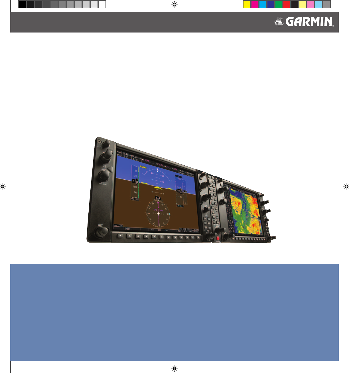
Garmin G1000™
VHF NAV/COM
Pilot’s Guide
DRAFT
Garmin Proprietary
G1000_COM-NAV_PG.indd a 2/10/2004, 8:46:12 AM

Preliminary
Garmin Proprietary Garmin G1000 VHF NAV/COM Pilot’s Guide
G1000_COM-NAV_PG.indd b 2/10/2004, 8:46:47 AM

Preliminary
Garmin Proprietary i
Garmin G1000 VHF NAV/COM Pilot’s Guide190-00302-01 Page Rev. 1
Copyright© 2004 Garmin Ltd. or its subsidiaries. All rights reserved.
This manual refl ects the operation of Main System Software version TBD or above. Some differences in operation may
be observed when comparing the information in this manual to earlier software versions.
Garmin International, Inc., 1200 East 151st Street, Olathe, Kansas 66062, U.S.A.
Tel: 913/397.8200 Fax: 913/397.8282
Garmin AT, Inc., 2345 Turner Road SE, Salem, OR 97302, U.S.A.
Tel: 503/391.3411 Fax 503/364.2138
Garmin (Europe) Ltd., Unit 5, The Quadrangle, Abbey Park Industrial Estate, Romsey, Hampshire S051 9DL, U.K.
Tel: 44/1794.519944 Fax: 44/1794.519222
Garmin Corporation, No. 68, Jangshu 2nd Road, Shijr, Taipei County, Taiwan
Tel: 886/02.2642.9199 Fax: 886/02.2642.9099
Web Site Address: www.garmin.com
Except as expressly provided herein, no part of this manual may be reproduced, copied, transmitted, disseminated,
downloaded or stored in any storage me di um, for any purpose without the express written permission of Garmin. Gar-
min hereby grants permission to download a single copy of this manual and of any revision to this manual onto a hard
drive or other electronic storage medium to be viewed for personal use, provided that such electronic or printed copy of
this manual or revision must contain the complete text of this copyright notice and provided further that any unauthor-
ized commercial distribution of this manual or any revision hereto is strictly prohibited.
Information in this document is subject to change without notice. Garmin reserves the right to change or improve their
products and to make changes in the content of this material without obligation to notify any person or organization of
such changes or improvements.
Garmin® is a registered trademark of Garmin Ltd. or its subsidiaries and may not be used without the express permission
of Garmin.
January 2004 Printed in the U.S.A.
i
COPYRIGHT
G1000_COM-NAV_PG.indd i 2/10/2004, 8:46:47 AM

Preliminary
Garmin Proprietary
ii Garmin G1000 VHF NAV/COM Pilot’s Guide 190-00302-01 Page Rev. 1
Revision Date of Revision Affected Pages Description Inserted
By/Date
1 01/12/04 All Preliminary Release for FAA
RECORD OF REVISIONS
G1000_COM-NAV_PG.indd ii 2/10/2004, 8:46:48 AM

Preliminary
Garmin Proprietary iii
Garmin G1000 VHF NAV/COM Pilot’s Guide190-00302-01 Page Rev. 1
LIST OF EFFECTIVE PAGES
Page Number Revision Page Number Revision
Cover
i-24
1
1
G1000_COM-NAV_PG.indd iii 2/10/2004, 8:46:48 AM

Preliminary
Garmin Proprietary
iv Garmin G1000 VHF NAV/COM Pilot’s Guide 190-00302-01 Page Rev. 1
TABLE OF CONTENTS
Copyright i
Record of Revisions ii
List of Effective Pages iii
Table of Contents iv
List of Figures v
Abbreviations & Acronyms vi
Section 1: Interface Description 1
1.1 Overview............................................................... 1
1.2 Windows and Fields ............................................. 2
1.3 Frequency Status ................................................. 2
1.4 Color Code ............................................................ 3
1.5 Tuning Box ............................................................ 3
1.6 Frequency Toggle Arrow ..................................... 3
1.7 Radio Status Indications ..................................... 3
1.8 Controls................................................................. 4
Section 2: COM Frequency Window 5
2.1 Overview............................................................... 5
2.2 Volume .................................................................. 5
2.3 Automatic Squelch............................................... 5
2.4 Switching The Tuning Box Between COM
Radios ................................................................... 5
2.5 Manually Tuning a COM Frequency .................... 6
2.6 Toggling COM Frequencies.................................. 6
2.7 Selecting COM RadioS ......................................... 6
2.8 Radio Status ......................................................... 7
2.9 Emergency Frequency (121.500 MHz)................. 7
Quickly Tuning and Activating 121.500 MHz 7
2.10 Stuck Microphone................................................ 7
Section 3: NAV Frequency Window 9
3.1 Overview............................................................... 9
3.2 Volume .................................................................. 9
3.3 Morse Code Identifi er.......................................... 9
3.4 Switching the Tuning Box Between NAV
Radios ................................................................. 10
3.5 Manually Tuning a NAV Frequency................... 10
3.6 Toggling NAV Frequencies................................. 10
3.7 Selecting a NAV Radio ....................................... 11
Section 4: Frequency Auto-tuning 13
4.1 Overview............................................................. 13
4.2 Auto-tuning on the PFD..................................... 13
4.3 Auto-tuning on the MFD ................................... 14
WPT - Airport Information Page 14
WPT - VOR Information Page 16
NRST - Nearest Airports Page 17
NRST - Nearest VOR Page 18
NRST - Nearest Frequencies Page 19
4.4 Auto-Tuning Upon Approach Activation
(NAV Frequencies).............................................. 20
Index 23
G1000_COM-NAV_PG.indd iv 2/10/2004, 8:46:49 AM

Preliminary
Garmin Proprietary v
Garmin G1000 VHF NAV/COM Pilot’s Guide190-00302-01 Page Rev. 1
LIST OF FIGURES
Figure 1-1 G1000 VHF NAV/COM Interface (PFD) ........1
Figure 1-2 Frequency Fields ........................................2
Figure 1-3 Frequency Toggle Arrow and Tuning Box ...3
Figure 1-4 NAV/COM Controls .....................................4
Figure 2-1 Overriding Automatic Squelch ...................5
Figure 2-2 Switching COM Radios...............................5
Figure 2-3 Toggling COM Frequencies.........................6
Figure 2-4 Selecting COM Radios................................6
Figure 2-5 Split COM ...................................................6
Figure 2-6 Radio Status Indications ............................7
Figure 2-7 Communication Failure ..............................7
Figure 2-8 Quickly Tuning 121.500 MHz ......................7
Figure 2-9 Stuck MIC Alert ..........................................7
Figure 3-1 ID Indication...............................................9
Figure 3-2 Morse Code Identifi er Audio......................9
Figure 3-3 Switching NAV Radios..............................10
Figure 3-4 Toggling NAV Frequencies........................10
Figure 3-5 Selecting NAV Radios...............................11
Figure 4-1 Loading Frequencies ................................13
Figure 4-2 Nearest Airports Window (PFD) ...............13
Figure 4-3 MFD Page Group Icon ..............................14
Figure 4-4 WPT - Airport Information Page (Info) .....14
Figure 4-5 WPT - Airport Information Page
(Approach)...............................................15
Figure 4-6 WPT - VOR Information Page....................16
Figure 4-7 NRST - Nearest Airport Page
(Frequencies) ...........................................17
Figure 4-8 NRST - Nearest VOR Page.........................18
Figure 4-9 NRST - Nearest Frequencies Page ............19
Figure 4-10 Selecting an Approach ...........................20
Figure 4-11 Loading an Approach .............................20
Figure 4-12 Activating an Approach..........................21
G1000_COM-NAV_PG.indd v 2/10/2004, 8:46:49 AM

Preliminary
Garmin Proprietary
vi Garmin G1000 VHF NAV/COM Pilot’s Guide 190-00302-01 Page Rev. 1
ABBREVIATIONS & ACRONYMS
APR Approach
ARTCC Air Route Traffi c Control Center
AUX Auxiliary
CDI Course Deviation Indicator
CDU Control Display Unit
COM Communication (radio)
ENT Enter
FMS Flight Management System
FPL Flight plan
FREQ Frequency
FSS Flight Service Station
GPS Global Positioning System
HSI Horizontal Situation Indicator
Hz Hertz
ID Morse code identifi er
ILS Instrument Landing System
kHz Kilohertz
LD NAV1 Load NAV1
LD NAV2 Load NAV2
MFD Multi Function Display
MHz Megahertz
MIC Microphone
MSA Minimum Safe Altitude
NAV Navigation (radio)
NRST Nearest
PFD Primary Flight Display
PROC Procedure(s)
PTT Push-to-Talk
RX Receive
SQ Squelch
STBY Standby
TIS Traffi c Information Service
TX Transmit
VFR Visual Flight Rules
VHF Very High Frequency
VOL Volume
VOR VHF Omnidirectional Range
WX Weather
Abbreviation or Acronym Defi nition Abbreviation or Acronym Defi nition
G1000_COM-NAV_PG.indd vi 2/10/2004, 8:46:50 AM
Preliminary
Garmin Proprietary 1
INTERFACE DESCRIPTION
190-00302-01 Page Rev. 1 Garmin G1000 VHF NAV/COM Pilot’s Guide
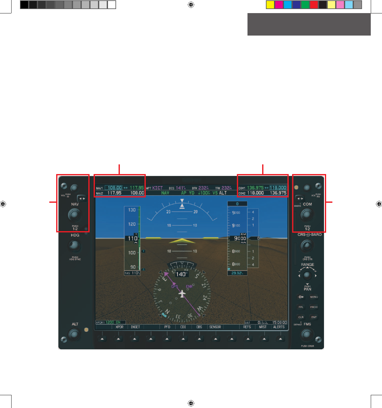
Section 1: Interface Description
1.1 OVERVIEW
On both the PFD and the MFD, the G1000 VHF NAV/
COM interface occupies the top portion of the panel. As
shown in Figure 1-1, the NAV-related controls, windows
and fi elds are located on the left side, whereas the COM-
related controls, windows and fi elds are located on the
right side.
This section provides information on the following
aspects of the G1000 VHF NAV/COM interface:
• Windows and fi elds
• Frequency status
• Color code
• Tuning box
• Frequency Toggle Arrow
• Radio status indications
• Controls
NAV
Controls COM
Controls
NAV Frequency Window COM Frequency Window
Figure 1-1 G1000 VHF NAV/COM Interface ( PFD)
G1000_COM-NAV_PG.indd 1 2/10/2004, 8:46:51 AM
Preliminary
Garmin Proprietary
2
INTERFACE DESCRIPTION
Garmin G1000 VHF NAV/COM Pilot’s Guide 190-00302-01 Page Rev. 1
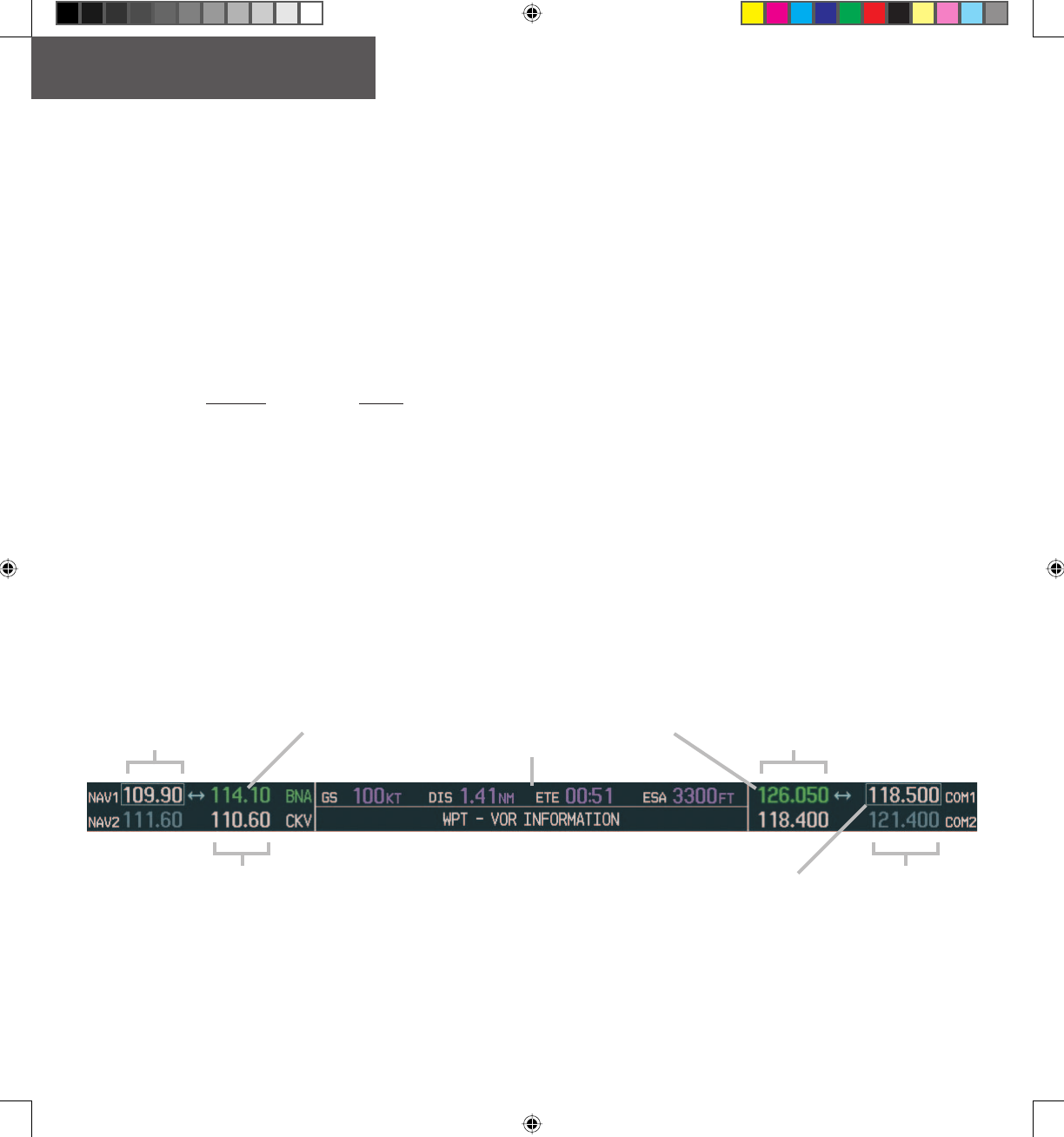
1.2 WINDOWS AND FIELDS
On both the PFD and the MFD, the NAV and COM
Frequency windows are located at the top of the display
on either side of the Navigation Status bar.
• The NAV Frequency window is displayed to the
left of the Navigation Status bar.
• The COM Frequency window is displayed to
the right of the Navigation Status bar.
Each radio frequency sub-window is composed of two
(2) fi elds, a standby fi eld and an active fi eld.
• In the NAV Frequency window, the active fre-
quency fi eld is located on the right side, while the
standby frequency fi eld is located on the left side.
• In the COM Frequency window, the active
frequency fi eld is located on the left side, while
the standby frequency fi eld is located on the right
side.
1.3 FREQUENCY STATUS
Frequencies on the VHF NAV/COM interface can ei-
ther be standby, active or selected.
• Standby – indicates that the frequency is located
in the standby fi eld of the associated radio.
• Active – indicates that the frequency is located in
the active fi eld of the associated radio.
• Selected – indicated that the frequency is active
and that the associated radio is selected:
– on the HSI (NAV frequencies)
– on the GMA 1347 audio panel (COM frequen-
cies) - COM MIC.
Standby NAV
Frequency Field
Active NAV
Frequency Field
Active COM
Frequency Field
Standby COM
Frequency Field
Figure 1-2 Frequency Fields
Selected NAV
Frequency Selected COM
Frequency
Navigation Status Bar
Tuning Box
G1000_COM-NAV_PG.indd 2 2/10/2004, 8:47:21 AM
Preliminary
Garmin Proprietary 3
OPERATION – COM
190-00302-01 Page Rev. 1 Garmin G1000 VHF NAV/COM Pilot’s Guide
1.4 COLOR CODE
Frequencies located in the active fi eld are displayed
in either green or white.
• An active frequency that is displayed in green
indicates that the corresponding radio is selected
(i.e., in use).
• An active frequency that is displayed in white
indicates that the corresponding radio is not
selected.
Frequencies located in the standby fi eld are displayed
in either white or gray.
• The standby frequency that appears in the tuning
box is displayed in white.
• The standby frequency that is not in the tuning
box is displayed in gray.
NOTE: In GPS mode, both active NAV frequencies
are displayed in white.
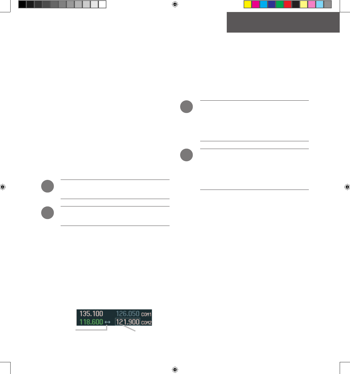
NOTE: In split COM mode, both active COM
frequencies are displayed in green.
1.5 TUNING BOX
On both the PFD and the MFD, a cyan tuning box ap-
pears over the standby frequency fi eld and can be moved
from one standby frequency fi eld to another for the pur-
pose of tuning or radio selection.
In both the COM and NAV windows, the frequency
toggle arrow appears next to the tuning box, between the
active and standby frequencies.
Frequency Toggle Arrow Frequency Tuning Box
Figure 1-3 Frequency Toggle Arrow and Tuning Box
1.6 FREQUENCY TOGGLE ARROW
A Frequency Toggle Arrow appears between the two
frequencies of the radio sub-window on which the fre-
quency tuning box is located. Pressing the dual COM or
NAV knob toggles both the frequency tuning box and the
Frequency Toggle Arrow between the radios.
NOTE: If the frequency tuning box is on a
selected COM sub-window when a signal
is received or transmitted for this radio, the
Frequency Toggle Arrow is replaced by an
RX or a TX
indication, respectively.
NOTE: When the desired frequency is entered in
the tuning box, it becomes a standby frequency.
Pressing the Frequency Toggle key places this
standby frequency into the active fi eld, and vice
versa.
1.7 RADIO STATUS INDICATIONS
• RX – When a signal is received on a COM radio,
a white RX indication appears to the right of the
corresponding COM frequency for the duration of
the signal reception.
• TX – When a microphone is keyed, a white TX
indication appears to the right of the correspond-
ing COM frequency for the duration of the signal
transmission.
• ID – When the VOL/PUSH ID knob is pressed, a
white ID indication appears to the left of the NAV
frequency on the selected NAV sub-window and
the Morse code identifi er audio for the selected
VOR frequency can be heard if the corresponding
NAV radio is selected on the audio panel.
!
!
!
!
G1000_COM-NAV_PG.indd 3 2/10/2004, 8:47:24 AM
Preliminary
Garmin Proprietary
4
OPERATION – COM
Garmin G1000 VHF NAV/COM Pilot’s Guide 190-00302-01 Page Rev. 1
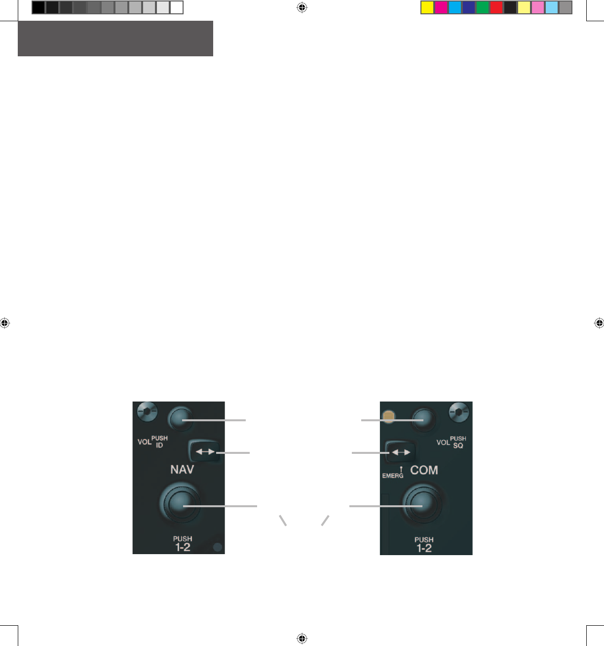
1.8 CONTROLS
The NAV Frequency window is controlled by knobs
and keys located to the left side of the display, while the
COM Frequency window is controlled by knobs and keys
located to the right side of the display.
The controls associated with the NAV window are:
• A VOL/PUSH ID knob
– Turn to adjust the NAV radio volume level.
– Press to turn the Morse code identifi er ON
and OFF.
• A Frequency Toggle key
– Press to toggle the NAV frequencies between
the active and standby fi elds.
• A dual NAV knob
– Turn to tune a NAV frequency in the NAV
tuning box (large knob for MHz; small knob
for kHz).
– Press to toggle the NAV tuning box between
the NAV radios.
The controls associated with the COM window are the
following ones:
• A VOL/PUSH SQ knob
– Turn to adjust the COM radio volume level.
– Press to turn squelch ON and OFF.
• A Frequency Toggle key
– Press to toggle the COM frequencies between
the active and standby fi elds.
• A dual COM knob
– Turn to tune a COM frequency in the COM
tuning box (large knob for MHz; small knob
for kHz).
– Press to toggle the COM tuning box between
the COM radios.
Figure 1-4 NAV/COM Controls
Frequency Toggle Key
Dual NAV
Knob Dual COM
Knob
VOL/PUSH
ID Knob VOL/PUSH
SQ Knob
NAV Controls COM Controls
• Tur n to tune in desired
frequencies.
• Press to switch radios.
G1000_COM-NAV_PG.indd 4 2/10/2004, 8:47:25 AM
Preliminary
Garmin Proprietary 5
OPERATION – COM
190-00302-01 Page Rev. 1 Garmin G1000 VHF NAV/COM Pilot’s Guide
Section 2: COM Frequency
Window
2.1 OVERVIEW
The G1000 COM radios operate in the aviation fre-
quency band of 118.000 to 136.990 MHz with either
25 kHz or 8.33 kHz channel spacing.
NOTE: COM channel spacing can be confi gured
through the MFD, in the System Setup Page of
the AUX Page group.
The Communications Frequency window is located
to the right of the Navigation Status bar, provides the
control and display of dual VHF Radio Communication
Transceivers ( COM1 and COM2) and displays the follow-
ing information:
• COM1 and COM2 active and standby frequencies
• Color-coded indication of the selected COM radio
• Indication of signal reception and transmission
NOTE: In split COM mode, both COM1 and
COM2 active frequencies are selected and thus
displayed in green.
2.2 VOLUME
Volume level for the COM radios can be adjusted
using the VOL/PUSH SQ knob (top knob on the right
side of the display) located above the COM Frequency
Toggle key. Turning the VOL/PUSH SQ knob clockwise
increases volume level, while turning this knob counter-
clockwise decreases volume level.
2.3 AUTOMATIC SQUELCH
Automatic squelch provides maximum sensitivity
to weaker signals while canceling most localized noise
sources. Automatic squelch can be disabled for a COM
radio by pressing the COM knob to select the desired
COM sub-window, then by pressing the VOL/PUSH SQ
knob.
When automatic squelch is disabled for a COM radio,
COM audio remains continuously open and an RX indi-
cation appears between the active and standby frequency
fi elds of this radio.
Figure 2-1 Overriding Automatic Squelch
NOTE: Pressing the VOL/PUSH SQ knob when
automatic squelch is disabled reactivates the
automatic squelch function.
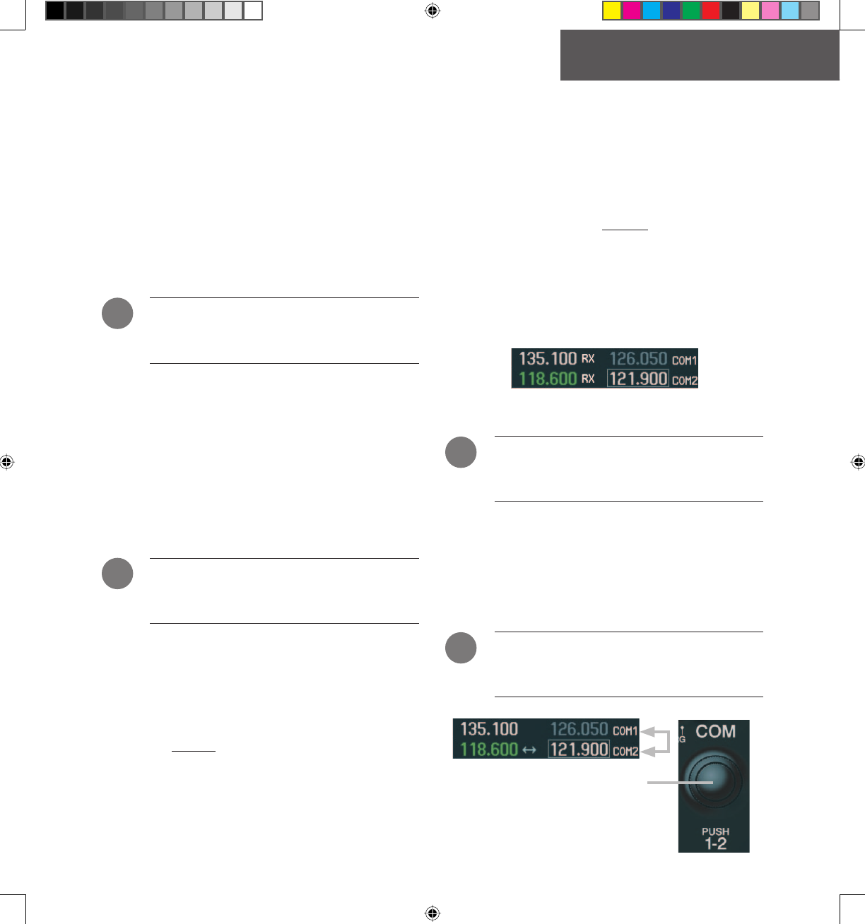
2.4 SWITCHING THE TUNING BOX
BETWEEN COM RADIOS
Pressing the COM knob toggles the frequency tuning
box between the COM1 and COM2 fi elds.
NOTE: When a different COM MIC is selected on
the audio panel, the frequency tuning box also
moves on both the PFD and MFD.
Figure 2-2 Switching COM Radios
Pushing the COM knob switches the tuning
box from one COM radio to the other.
!
!
!
!
G1000_COM-NAV_PG.indd 5 2/10/2004, 8:47:36 AM
Preliminary
Garmin Proprietary
6
OPERATION – NAV
Garmin G1000 VHF NAV/COM Pilot’s Guide 190-00302-01 Page Rev. 1
2.5 MANUALLY TUNING A COM
FREQUENCY
COM frequency manual tuning is performed by using
the dual COM knob.
• The MHz (left) portion of the frequency can be
tuned by turning the large COM knob.
• The kHz (right) portion of the frequency can be
tuned by turning the small COM knob.
Turning either knob clockwise increases the tuned
frequency. Conversely, turning either knob counterclock-
wise decreases the tuned frequency. The tuned frequency
is placed in the standby frequency fi eld of the COM Fre-
quency window.
NOTE: Only when tuning frequencies manually
can the standby frequency fi eld for a COM radio
be tuned to the same frequency as that located
in the active fi eld for the same COM radio.
2.6 TOGGLING COM FREQUENCIES
Pressing the COM Frequency Toggle key toggles the
COM frequencies between the active and standby fi elds of
the COM radio on which the Frequency Toggle Arrow
is located.
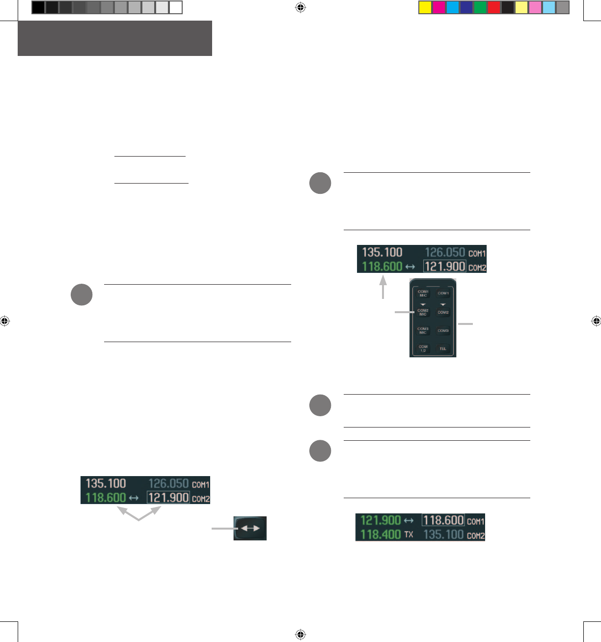
2.7 SELECTING COM RADIOS
To be selected, a COM frequency must be placed in
the active fi eld and the corresponding COM radio must
be selected on the GMA 1347 audio panel. When se-
lected, the COM frequency of the selected COM radio is
displayed in green.
NOTE: A COM radio can only be selected through
the GMA 1347 audio panel (COM MIC key).
Please, see Garmin GMA 1347 Pilot’s Guide
for details.
Figure 2-4 Selecting COM Radios
COM radio selection is
performed via the audio
panel. Top portion of
the GMA 1347
audio panel
NOTE: The selected COM frequency is always
displayed in green.
NOTE: In split COM mode, both COM1 and
COM2 radios are selected; the associated active
frequencies are thus displayed in green in the
COM Frequency window.
Figure 2-5 Split COM
!
!
!
!
Figure 2-3 Toggling COM Frequencies
Pressing the COM Frequency Toggle
key toggles the COM frequencies.
G1000_COM-NAV_PG.indd 6 2/10/2004, 8:47:40 AM
Preliminary
Garmin Proprietary 7
OPERATION – NAV
190-00302-01 Page Rev. 1 Garmin G1000 VHF NAV/COM Pilot’s Guide
2.8 RADIO STATUS
When a microphone is keyed, a white TX indication
appears between the active COM frequency and the
standby COM frequency to indicate that a transmission
is in progress. The TX indication disappears once COM
transmission is completed.
When a COM signal is received, a white RX indication
appears to the right of the active COM frequency to indi-
cate that a COM signal reception is in progress. The RX
indication disappears once COM signal reception is over.
Figure 2-6 Radio Status Indications
NOTE: If a signal is transmitted or received on
a COM radio for which frequency toggling is
enabled (i.e., on which the tuning box is located),
the Frequency Toggle Arrow disappears and
is replaced by a TX or an RX indication, respec-
tively.
2.9 EMERGENCY FREQUENCY
(121.500 MHZ)
If data for the selected COM frequency is not received
for a duration of one second, a communication failure is
assumed by the system and the selected frequency is auto-
matically changed to the emergency frequency (121.500
MHz).
Figure 2-7 Communication Failure
NOTE: In the event of a dual CDU failure, the
emergency frequency (121.500 MHz) automati-
cally becomes available to the pilot through the
pilot headset.
Quickly Tuning and Activating 121.500 MHz
Pressing and holding the COM Frequency Toggle key
for approximately two (2) seconds automatically loads the
emergency COM frequency (121.500 MHz) in the active
frequency fi eld of the COM radio for which frequency
toggling is enabled.
Figure 2-8 Quickly Tuning 121.500 MHz
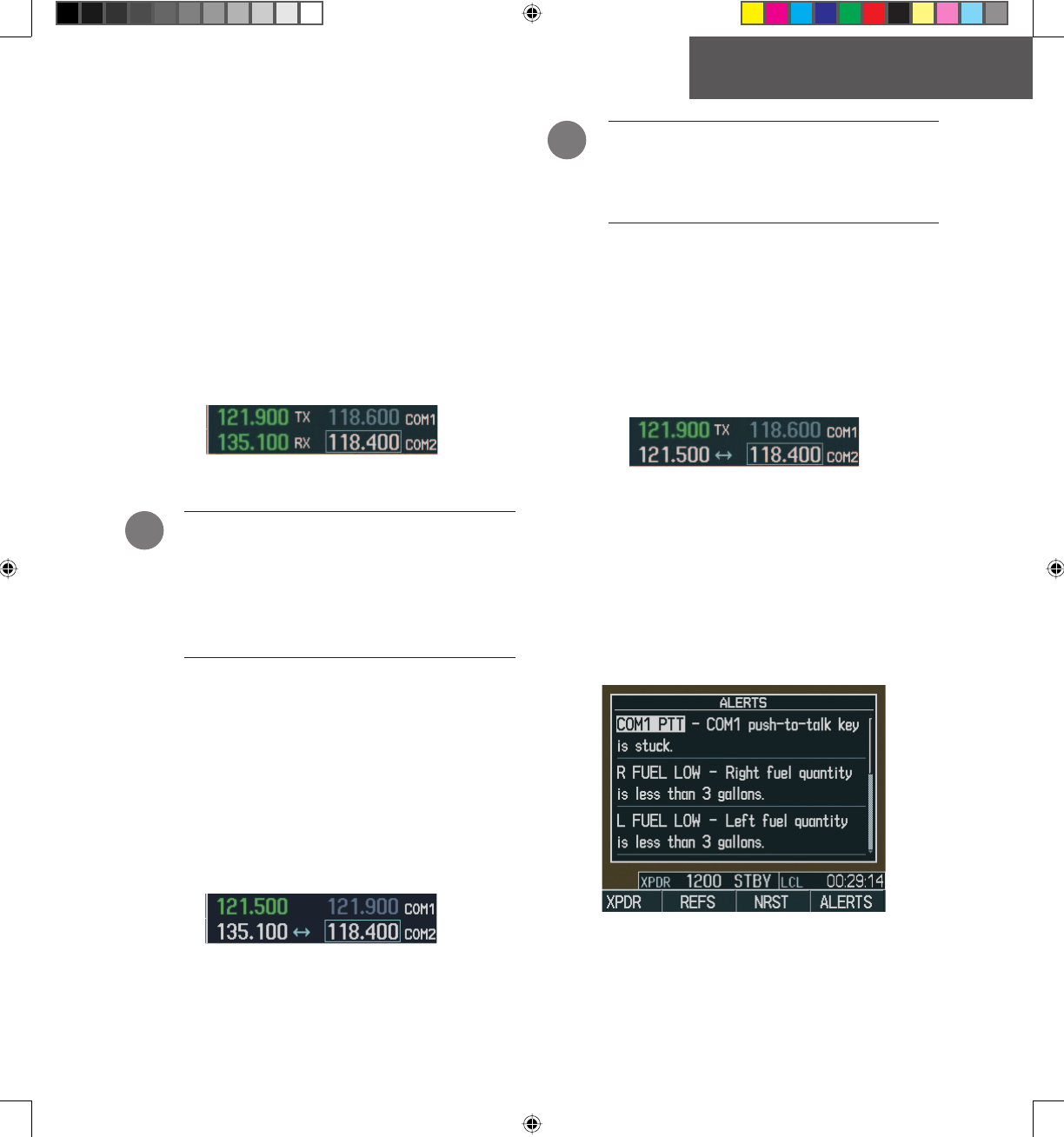
2.10 STUCK MICROPHONE
If the COM1 (or COM2) Remote Transfer key be-
comes stuck, an alert appears on the PFD to advise the
crew of a stuck COM microphone. Transmit capability is
reset after 35 seconds of continuous transmitting.
Figure 2-9 Stuck MIC Alert
!
!
G1000_COM-NAV_PG.indd 7 2/10/2004, 8:47:49 AM

Preliminary
Garmin Proprietary
8
OPERATION – AUTO-TUNING
Garmin G1000 VHF NAV/COM Pilot’s Guide 190-00302-01 Page Rev. 1
This page intentionally left blank.
G1000_COM-NAV_PG.indd 8 2/10/2004, 8:47:52 AM
Preliminary
Garmin Proprietary 9
OPERATION – AUTO-TUNING
190-00302-01 Page Rev. 1 Garmin G1000 VHF NAV/COM Pilot’s Guide
Section 3: NAV Frequency
Window
3.1 OVERVIEW
The G1000 NAV radios operate in the aviation fre-
quency band of 108.00 to 117.95 MHz, with 50 kHz
channel spacing.
The Navigation Frequency window is located to the
left of the Navigation Status bar, provides the control and
display of dual VOR/ILS receivers ( NAV1 and NAV2) and
displays the following information:
• NAV1 and NAV2 active and standby frequencies
• NAV1 or NAV2 identifi er indication (if the active
NAV frequency is a valid frequency and its Morse
code identifi er signal is received by the system).
• Color code indication of the selected NAV receiver
• Indication of the Morse code identifi er fi lter status
3.2 VOLUME
Volume level for the NAV radios can be adjusted by
using the VOL/PUSH ID knob (top knob on the left
side of the display) located above the NAV Frequency
Toggle key. Turning the VOL/PUSH ID knob clockwise
increases volume level, while turning this knob counter-
clockwise decreases volume level.
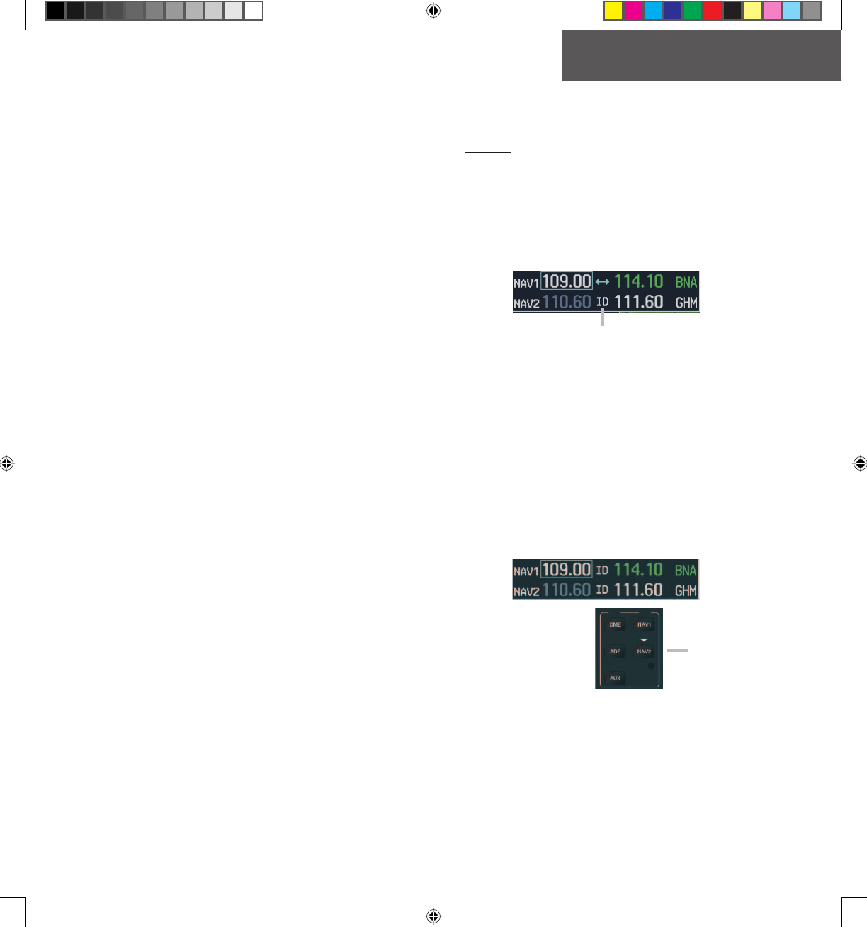
3.3 MORSE CODE IDENTIFIER
Pressing the VOL/PUSH ID knob toggles the Morse
code identifi er fi lter ON and OFF for the active NAV fre-
quency next to which the tuning box is located. When
the Morse code identifi er fi lter is ON, an ID indication
appears to the left of the corresponding active NAV fre-
quency.
Figure 3-1 ID Indication
The Morse code identifi er fi lter is ON for
the GHM VOR.
The Morse code identifi er for an active NAV frequency
can only be heard if the Morse code identifi er fi lter for
the corresponding NAV radio is turned on (i.e., if the ID
indication appears next to the active NAV frequency) and
if the corresponding NAV radio is selected on the GMA
1347 audio panel (i.e., the associated NAV radio annun-
ciator lights are illuminated).
Here, since NAV2 is the only
NAV radio selected on the
audio panel, only the Morse
code identifi er for the GHM
VOR can be heard.
NAV portion of
the GMA 1347
audio panel
Figure 3-2 Morse Code Identifi er Audio
G1000_COM-NAV_PG.indd 9 2/10/2004, 8:47:53 AM
Preliminary
Garmin Proprietary
10
OPERATION – AUTO-TUNING
Garmin G1000 VHF NAV/COM Pilot’s Guide 190-00302-01 Page Rev. 1
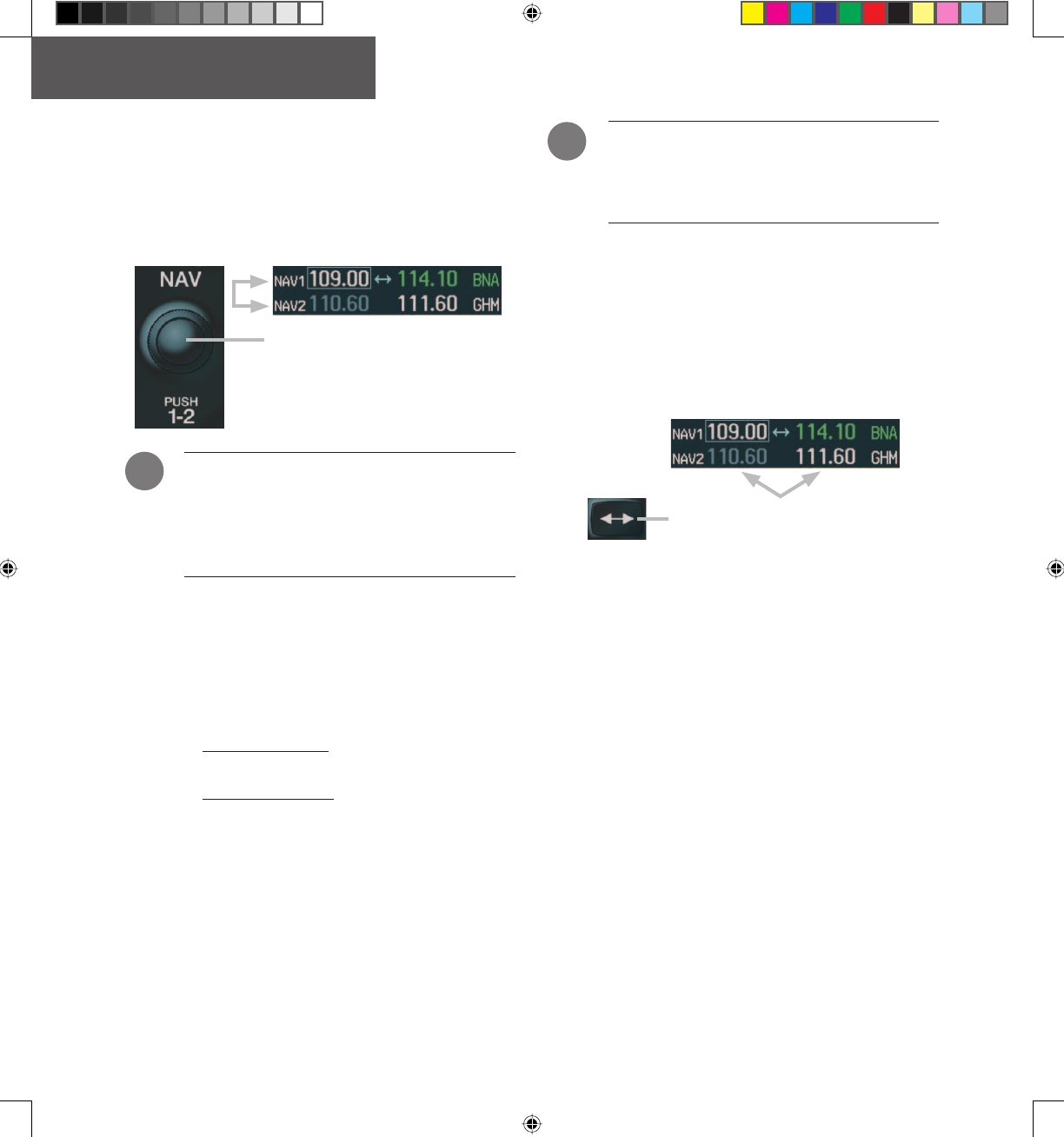
3.4 SWITCHING THE TUNING BOX
BETWEEN NAV RADIOS
Pressing the dual NAV knob toggles the frequency
tuning box between the NAV1 and NAV2 sub-windows.
Pushing the NAV knob switches the tuning
box from one NAV radio to the other.
Figure 3-3 Switching NAV Radios
NOTE: When a different NAV radio is selected
on the HSI via the CDI key, the NAV frequency
tuning box also moves on the PFD and MFD.
However, the NAV frequency tuning box does
not move when GPS mode is selected.
3.5 MANUALLY TUNING A NAV
FREQUENCY
NAV frequency manual tuning is performed by using
the dual NAV knob.
• The MHz (left) portion of the frequency can be
tuned by turning the large NAV knob.
• The kHz (right) portion of the frequency can be
tuned by turning the small NAV knob.
Turning either knob clockwise increases the tuned
frequency. Conversely, turning either knob counterclock-
wise decreases the tuned frequency. The tuned frequency
is placed in the standby frequency fi eld of the NAV Fre-
quency window.
NOTE: Only when tuning frequencies manually
can the standby frequency fi eld for a NAV radio
be tuned to the same frequency as that located
in the active fi eld for the same NAV radio.
3.6 TOGGLING NAV FREQUENCIES
Pressing the NAV Frequency Toggle key toggles the
NAV frequencies between the active and standby fi elds of
the NAV radio on which the Frequency Toggle Arrow
is located.
Figure 3-4 Toggling NAV Frequencies
Pressing the NAV Frequency Toggle
key toggles the NAV frequencies.
!
!
G1000_COM-NAV_PG.indd 10 2/10/2004, 8:47:56 AM
Preliminary
Garmin Proprietary 11
OPERATION – NAV
190-00302-01 Page Rev. 1 Garmin G1000 VHF NAV/COM Pilot’s Guide
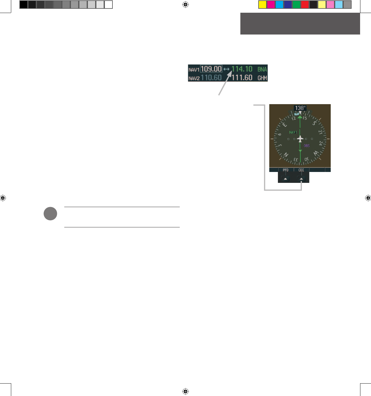
3.7 SELECTING A NAV RADIO
To be selected, a NAV frequency must be placed in
the active fi eld and the corresponding NAV radio must be
displayed on the HSI. When selected, the active NAV fre-
quency of the selected NAV radio is displayed in green.
The desired NAV radio can be selected using the CDI
softkey. The three navigation modes that can be selected
with the CDI softkey are as follows:
• NAV1 – If NAV1 is selected as the NAV radio, a
single green arrow is displayed on the HSI and
the active NAV1 frequency is displayed in green.
• NAV2 – If NAV2 is selected as the NAV radio, a
double green arrow is displayed on the HSI and
the active NAV2 frequency is displayed in green.
• GPS Mode – If GPS mode is selected, a single
magenta arrow appears on the HSI and none of
the active NAV frequencies are selected.
NOTE: In GPS mode, all active NAV frequencies
are displayed in white.
When a VOR signal is received, the corresponding
VOR name identifi er is displayed to the right of the as-
sociated active NAV frequency.
Figure 3-5 Selecting NAV Radios
NAV radio selection is
performed via the CDI
softkey.
!
G1000_COM-NAV_PG.indd 11 2/10/2004, 8:47:59 AM

Preliminary
Garmin Proprietary
12
OPERATION – NAV
Garmin G1000 VHF NAV/COM Pilot’s Guide 190-00302-01 Page Rev. 1
This page intentionally left blank.
G1000_COM-NAV_PG.indd 12 2/10/2004, 8:48:04 AM
Preliminary
Garmin Proprietary 13
OPERATION – AUTO-TUNING
190-00302-01 Page Rev. 1 Garmin G1000 VHF NAV/COM Pilot’s Guide
Section 4: Frequency Auto-tuning
4.1 OVERVIEW
The G1000 system offers multiple auto-tuning capa-
bilities that help to reduce cockpit workload. The PFD
allows for the auto-tuning of COM frequencies associated
with the nearest airports, while the MFD provides auto-
tuning of both COM and NAV frequencies from various
pages. In addition, regardless of the display, the pertinent
primary NAV frequency is entered systematically in the
NAV window upon approach loading or activation.
In brief, frequencies can be automatically loaded in
their respective frequency windows in the following
ways:
• By using the ENT key when the frequency is
highlighted on the appropriate page ( PFD and
MFD).
• By using the LD NAV1 and LD NAV2 softkeys
when on the appropriate page ( MFD only).
• Upon loading or activating an approach ( PFD and
MFD).
NOTE: Turn the FMS knob to scroll through a
list of frequencies.
Turn the FMS
knob to scroll
through a list of
frequencies.
Press ENT to load a
highlighted frequency
in the associated
frequency window.
Figure 4-1 Loading Frequencies
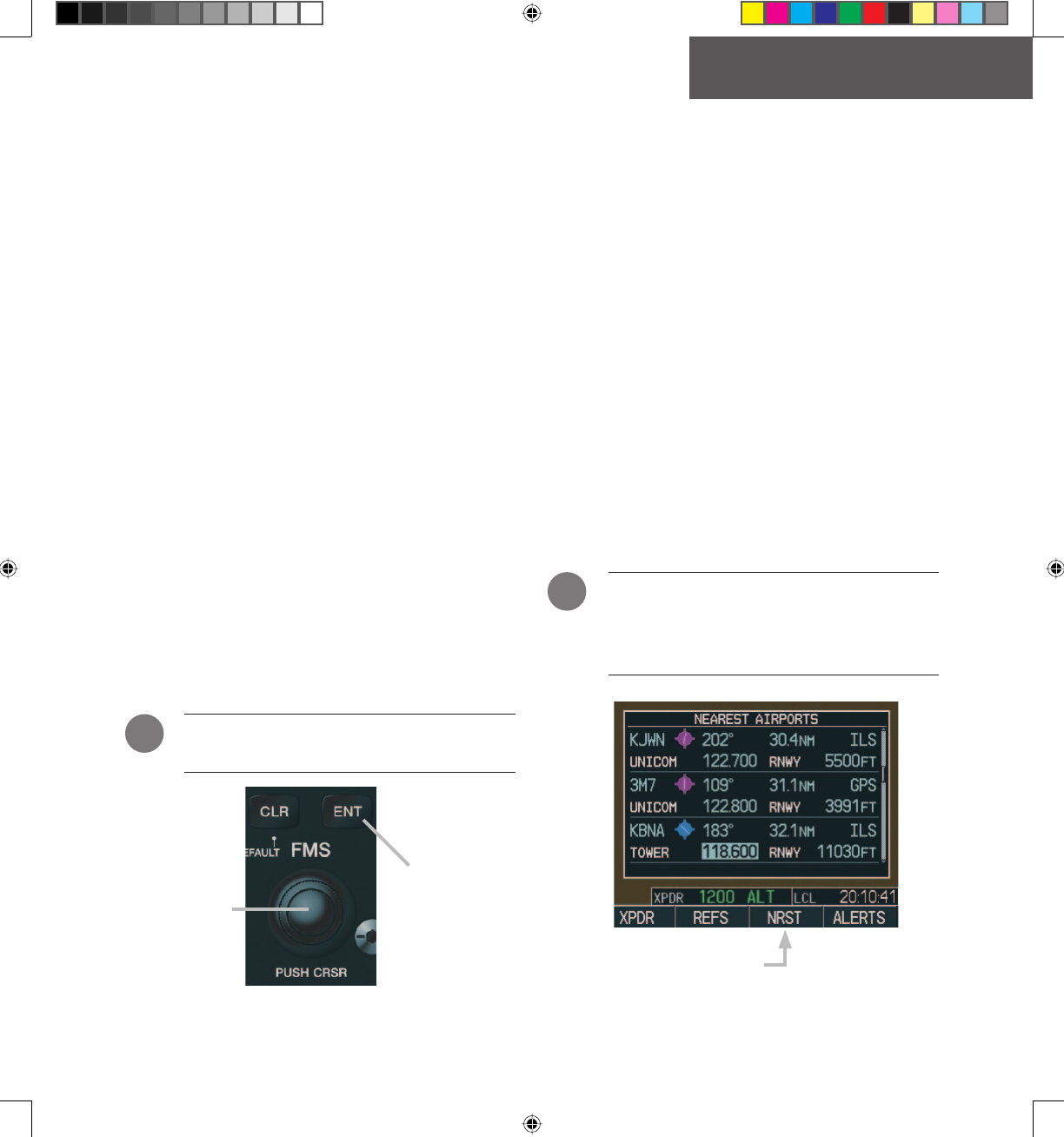
4.2 AUTO-TUNING ON THE PFD
COM frequencies for the nearest airports may be
viewed and automatically loaded from the Nearest Airport
window on the PFD.
To auto-tune a COM frequency for a nearby
airport:
1. Press the
NRST
softkey to open the Nearest
Airports window, which displays the list of
airport identifi ers and corresponding COM
frequencies.
2. Turn either
FMS
knob to highlight the desired
COM frequency, and ensure that the COM
frequency tuning box is on the desired COM
sub-window.
3. Press the
ENT
key to load the COM frequency
in the COM tuning box.
NOTE: When the desired frequency is entered in
the tuning box, it becomes a standby frequency.
Pressing the Frequency Toggle key places this
standby frequency into the active fi eld.
Figure 4-2 Nearest Airports Window ( PFD)
Pressing the NRST softkey opens
the Nearest Airports window.
!
!
G1000_COM-NAV_PG.indd 13 2/10/2004, 8:48:04 AM
Preliminary
Garmin Proprietary
14
OPERATION – AUTO-TUNING
Garmin G1000 VHF NAV/COM Pilot’s Guide 190-00302-01 Page Rev. 1
4.3 AUTO-TUNING ON THE MFD
Frequencies can be automatically loaded from the fol-
lowing MFD pages:
• WPT – Airport Information
• WPT – VOR Information
• NRST – Nearest Airports
• NRST – Nearest VOR
• NRST – Nearest Frequencies
Figure 4-3 MFD Page Group Icon
NOTE: Upon any VOR/ILS approach activation,
the appropriate NAV frequency is automatically
loaded into the standby fi eld of the selected NAV
radio, regardless of the current MFD page that
is displayed.
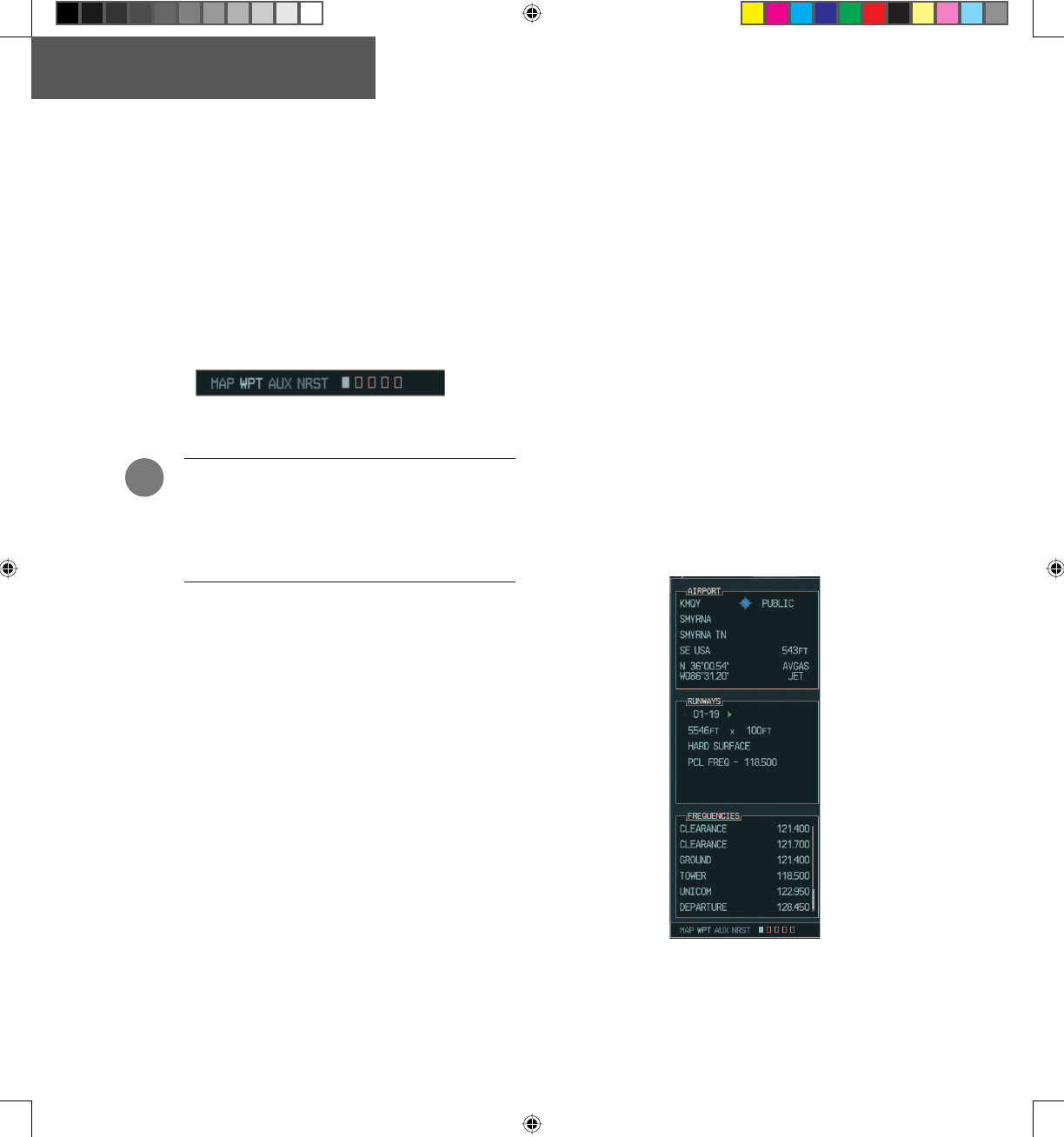
WPT - Airport Information Page
The Airport Information Page displays runway infor-
mation and a list of frequencies pertinent to the selected
airport identifi er as well as departure, arrival and ap-
proach information.
To display the entire list of frequencies for
a desired airport:
1. On the Airport Information Page, press the
INFO
softkey to display runway and frequency
information for a specifi c airport.
2. Press the
FMS
knob to activate the highlight
in the window.
3. Select the desired airport identifi er by turn-
ing the
FMS
knob and press
ENT
. A list of all
available frequencies for the selected airport
appears.
Figure 4-4 WPT - Airport Information Page (Info)
!
G1000_COM-NAV_PG.indd 14 2/10/2004, 8:48:09 AM
Preliminary
Garmin Proprietary 15
OPERATION – AUTO-TUNING
190-00302-01 Page Rev. 1 Garmin G1000 VHF NAV/COM Pilot’s Guide
To load the desired COM frequency auto-
matically into the COM tuning box:
1. When the list of frequencies for the selected
airport is displayed, highlight the desired fre-
quency by turning the large
FMS
knob.
2. Press
ENT
.
NOTE
:
The runway PCL frequency (located in the
Runways box of the INFO portion of the Airport
Information Page) may also be highlighted with
the large FMS knob and automatically loaded
into the COM tuning box by pressing ENT.
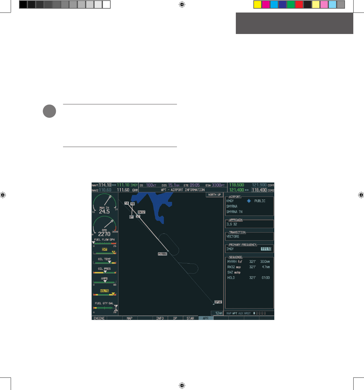
To load the primary approach NAV fre-
quency automatically into the NAV tuning
box:
1 On the Airport Information Page, press the
APR
softkey to display approach information for a
specifi c airport.
2. Press the
FMS
knob to activate the highlight in
the window.
3. Turn the large
FMS
knob to highlight the
primary NAV frequency located in the Primary
Frequency box.
4. Press
ENT
.
Figure 4-5 WPT - Airport Information Page (Approach)
!
G1000_COM-NAV_PG.indd 15 2/10/2004, 8:48:12 AM
Preliminary
Garmin Proprietary
16
OPERATION – AUTO-TUNING
Garmin G1000 VHF NAV/COM Pilot’s Guide 190-00302-01 Page Rev. 1
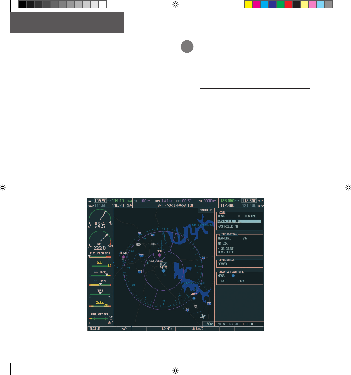
WPT - VOR Information Page
The VOR Information Page displays information spe-
cifi c to individual VORs, including the airport that is near-
est to the selected VOR. On this page, the VOR frequency
for a selected VOR can be loaded automatically with the
LD NAV1 or LD NAV2 softkeys.
To load a VOR frequency automatically in
the NAV window:
1. On the VOR Information Page, press the
FMS
knob to activate the VOR information
window.
2. Turn the
FMS
knob as needed to select the
desired VOR and press
ENT
to validate the
selection.
3. Press either the
LD NAV1
or the
LD NAV2
softkey
to load the VOR frequency in the corresponding
NAV standby fi eld.
NOTE
:
If the MENU key is pressed when on the
VOR Information Page, the ‘View Recent VOR
List’ menu option is displayed for quick access
to recently used VORs. However, if no VOR fre-
quencies have been tuned, this menu option is
grayed out.
Figure 4-6 WPT - VOR Information Page
!
G1000_COM-NAV_PG.indd 16 2/10/2004, 8:48:18 AM
Preliminary
Garmin Proprietary 17
OPERATION – AUTO-TUNING
190-00302-01 Page Rev. 1 Garmin G1000 VHF NAV/COM Pilot’s Guide
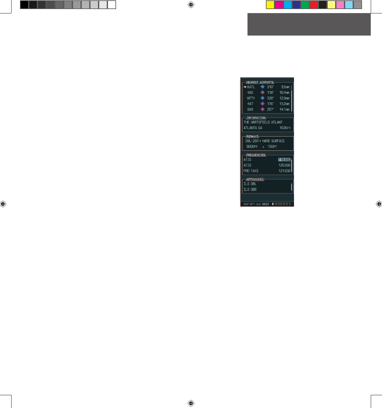
NRST - Nearest Airports Page
The Nearest Airports Page displays a list of the nearest
airports as well as related runway, frequency and approach
information. On this page, any frequency associated with
the selected airport can be loaded into the NAV or COM
Frequency window.
To display the entire list of frequencies for
a nearby airport and load a frequency from
that list:
1. On the Nearest Airport Page, press the
FMS
knob to activate the highlight in the Nearest
Airports sub-window.
2. Scroll through the list of nearest airport identi-
fi ers to the desired nearest airport by turning
the
FMS
knob.
3. Press the
FREQ
softkey to activate the highlight
in the Frequencies sub-window.
4. Turn the
FMS
knob to scroll through the list of
frequencies for the selected airport.
5. When the desired frequency is highlighted,
press
ENT
to load it in the tuning box of the
appropriate window (NAV or COM).
Figure 4-7 NRST - Nearest Airport Page (Frequencies)
G1000_COM-NAV_PG.indd 17 2/10/2004, 8:48:26 AM
Preliminary
Garmin Proprietary
18
OPERATION – AUTO-TUNING
Garmin G1000 VHF NAV/COM Pilot’s Guide 190-00302-01 Page Rev. 1
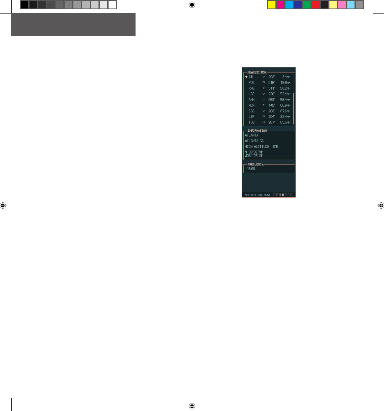
NRST - Nearest VOR Page
The Nearest VOR Page displays a list of the nearest
VORs together with related information, including the as-
sociated VOR frequency. On this page, the VOR frequen-
cy for a selected VOR can be loaded automatically in the
NAV window with the LD NAV1 or LD NAV2 softkeys.
To load a VOR frequency automatically in
the NAV window:
1. On the Nearest VOR Page, press the
FMS
knob
to activate the Nearest VOR window.
2. Turn the
FMS
knob (or press the
ENT
key as
needed) to scroll through the list of nearest
VORs.
3. When the desired VOR is highlighted, press
the
LD NAV1
or
LD NAV2
softkey to load the
frequency in the corresponding NAV standby
fi eld.
Figure 4-8 NRST - Nearest VOR Page
G1000_COM-NAV_PG.indd 18 2/10/2004, 8:48:29 AM
Preliminary
Garmin Proprietary 19
OPERATION – AUTO-TUNING
190-00302-01 Page Rev. 1 Garmin G1000 VHF NAV/COM Pilot’s Guide
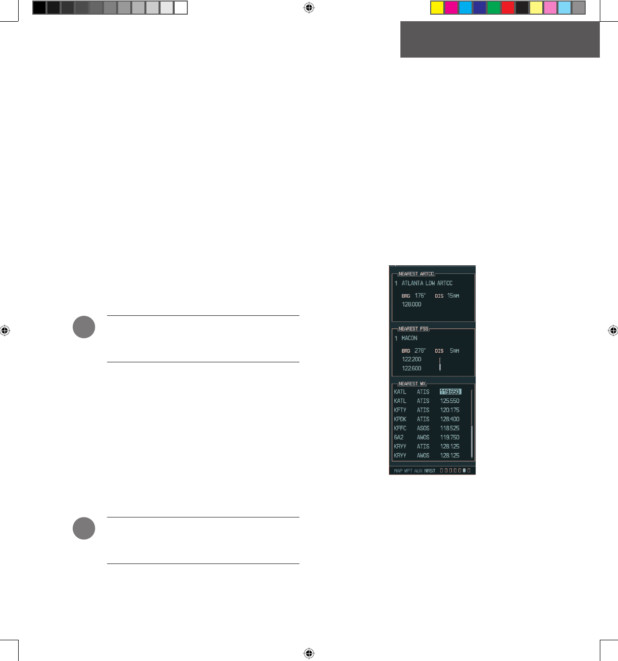
NRST - Nearest Frequencies Page
The Nearest Frequencies Page displays a list of nearest
ARTCC, FSS and WX frequencies. For the purpose of
frequency selection, the highlight can be activated on the
ARTCC, FSS or WX sub-windows by using the ARTCC,
FSS and WX softkeys, respectively.
To view a nearest ARTCC frequency and
load it automatically in the standby fre-
quency fi eld:
1. Press the
ARTCC
softkey to activate the high-
light in the Nearest ARTCC sub-window.
2. Using the
FMS
knob, highlight the desired
ARTCC frequency.
3. Press
ENT
to load the desired ARTCC frequency
in the standby frequency fi eld.
NOTE: The Nearest ARTCC sub-window contains
a ranked list of ARTCC frequencies as well as
associated bearing and distance information.
To view a nearest FSS frequency and load
it automatically in the standby frequency
fi eld:
1. Press the
FSS
softkey to activate the highlight
in the Nearest FSS sub-window.
2. Using the
FMS
knob, highlight the desired FSS
frequency.
3. Press
ENT
to load the desired FSS frequency in
the standby frequency fi eld.
NOTE: The Nearest FSS sub-window contains a
ranked list of FSS frequencies as well as associ-
ated bearing and distance information.
To view a nearest WX frequency and load
it automatically in the standby frequency
fi eld:
1. Press the
WX
softkey to activate the highlight
in the Nearest WX sub-window.
2. Using the
FMS
knob, highlight the desired WX
frequency.
3. Press
ENT
to load the desired WX frequency in
the standby frequency fi eld.
Figure 4-9 NRST - Nearest Frequencies Page
!
!
G1000_COM-NAV_PG.indd 19 2/10/2004, 8:48:31 AM
Preliminary
Garmin Proprietary
20
OPERATION – AUTO-TUNING
Garmin G1000 VHF NAV/COM Pilot’s Guide 190-00302-01 Page Rev. 1
4.4 AUTO-TUNING UPON APPROACH
ACTIVATION (NAV FREQUENCIES)
NAV frequencies can be automatically loaded in the
NAV Frequency window upon approach activation, re-
gardless of the display unit being used.
NOTE: The primary NAV frequency also becomes
auto-tuned upon loading of an approach.
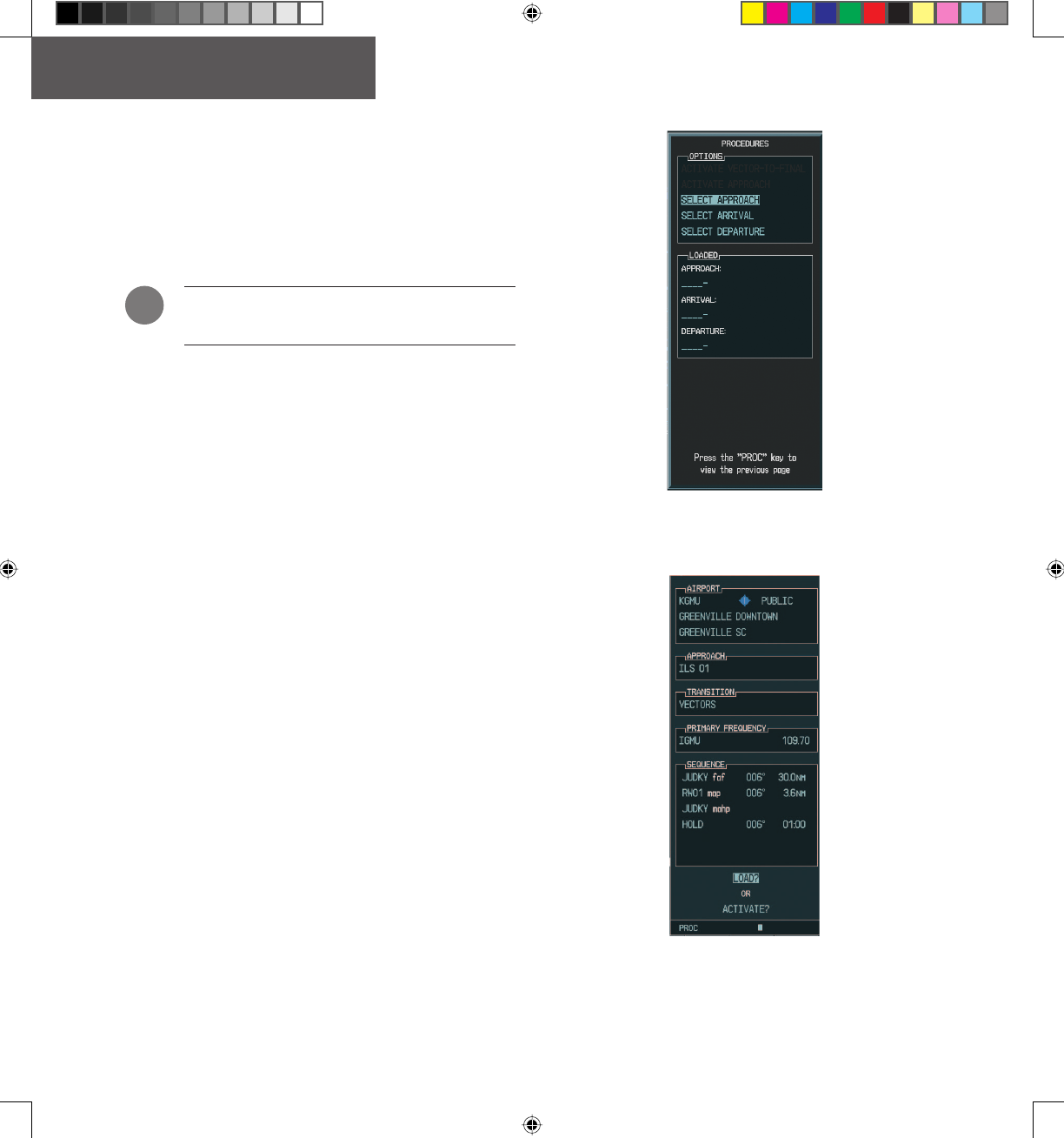
To auto-tune a NAV frequency if the
desired approach is not already loaded:
1. Press the
PROC
key to open the Procedures
window.
2. Turn the large
FMS
knob to highlight the
‘SELECT APPROACH’ menu option and press
ENT
.
3. Select the desired airport, VOR/ILS approach
and transition, using both the
FMS
knob and
the
ENT
key as needed.
4. Highlight either the ‘LOAD?’ or ‘ACTIVATE?’
prompt, using the
FMS
knob and press
ENT
.
The primary NAV frequency for the activated
approach becomes tuned in the standby fi eld
of the selected NAV radio.
Figure 4-10 Selecting an Approach
Figure 4-11 Loading an Approach
!
G1000_COM-NAV_PG.indd 20 2/10/2004, 8:48:34 AM
Preliminary
Garmin Proprietary 21
OPERATION – AUTO-TUNING
190-00302-01 Page Rev. 1 Garmin G1000 VHF NAV/COM Pilot’s Guide
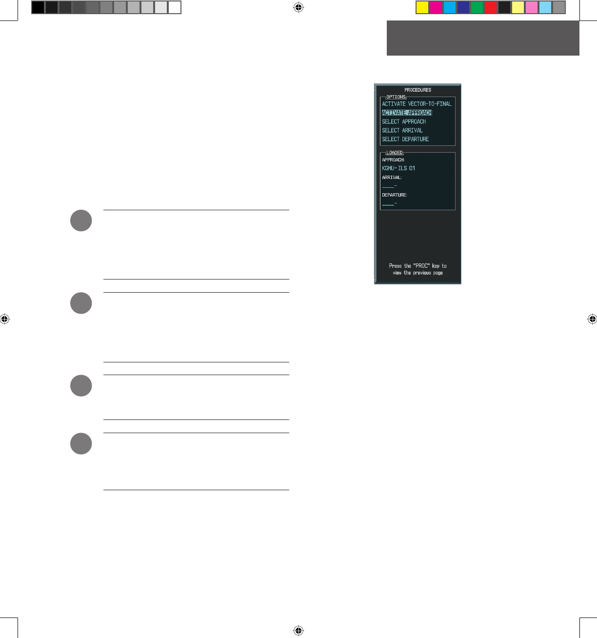
To auto-tune a NAV frequency if the
desired approach is already loaded:
1. Press the
PROC
key to open the Procedures
window.
2. Turn the large
FMS
knob to highlight the ‘ACTI-
VATE APPROACH’ menu option and press
ENT
.
The approach primary NAV frequency becomes
automatically tuned in the standby fi eld of the
selected NAV radio.
NOTE: Before loading or activating an approach,
the associated primary NAV frequency may be
loaded in the NAV tuning box by highlighting the
frequency in the Select Approach window via the
FMS knob, then by pressing ENT.
NOTE: Automatic loading of the NAV frequency
also occurs upon vector-to-fi nal activation, if the
NAV frequency is not already loaded in either
the standby or the active fi eld of the selected
NAV radio.
NOTE: Approach activation can also be per-
formed via the MENU key when the Flight Plan
window is open.
NOTE: If the system is in GPS mode when a VOR/
ILS approach is loaded or activated, the approach
primary NAV frequency is automatically loaded
in the active fi eld of NAV1.
Figure 4-12 Activating an Approach
!
!
!
!
G1000_COM-NAV_PG.indd 21 2/10/2004, 8:48:39 AM

Preliminary
Garmin Proprietary
22
OPERATION – AUTO-TUNING
Garmin G1000 VHF NAV/COM Pilot’s Guide 190-00302-01 Page Rev. 1
This page intentionally left blank.
G1000_COM-NAV_PG.indd 22 2/10/2004, 8:48:41 AM

Preliminary
Garmin Proprietary 23
INDEX
190-00302-01 Page Rev. 1 Garmin G1000 VHF NAV/COM Pilot’s Guide
A
Abbreviations & Acronyms vi
Active 5, 6, 9
Active fi eld 2, 3, 6, 10, 11, 13, 21
Active frequency 2, 3, 7
Airport Information 14, 15
Annunciator lights 9
Approach activation 13, 14, 20
APR softkey 15
ARTCC 19
ARTCC softkey 19
Audio Panel 2, 3, 5, 6, 9
Automatic squelch 5
AUX Page group 5
Aviation frequency band 5, 9
C
CDI softkey 11
Radio status indications 1
Color 1, 3, 5, 9
Green 3, 5, 6, 11
Magenta 11
White 3, 7, 11
Color code 1, 9
COM1 5, 6, 7
COM2 5, 6, 7
COM Frequency Window 1
COM knob 4, 5, 6, 10
Controls 1, 4
Copyright i
Cyan 3
D
Dual CDU failure 7
E
Emergency frequency 7
F
FMS knob 13-21
Frequency status 1
Frequency Toggle Arrow 1, 3, 7
Frequency Toggle key 3-7, 9, 10, 13
FREQ softkey 17
Front Panel Controls
AUX vi
SPKR vi
SQ vi
FSS 19
FSS softkey 19
G
GPS Mode 11
Gray 3
Green 3, 5, 6, 11
H
HI SENS vi
HSI 2, 11
I
ICS vi
ID 3, 4, 9
INFO softkey 14
Interface Description 1
K
KHz 6, 10
L
LD NAV1 13, 16, 18
LD NAV2 13, 16, 18
LED vi
List of Effective Pages iii
List of Figures v
M
Manual tuning 6, 10
MENU key 16, 21
MFD 1-3, 5, 10, 13, 14
MFD Page Group 14
Morse code identifi er 3, 4, 9
N
NAV1 5, 9, 10
NAV2 9, 10
Navigation modes 11
Navigation Status bar 2, 5, 9
NAV Frequency Window 1
NAV knob 3, 4, 10
Nearest Airports 13, 14, 17
Nearest Frequencies 14, 19
P
PFD 1-3, 5, 7, 10, 13
Primary NAV frequency 13, 15, 20, 21
PROC key 20, 21
Q
Quickly Tuning 121.500 MHz 7
R
Recently used VORs 16
Record of Revisions ii
Registered Trademark i
Remote Transfer key 7
Revision ii, iii
Runway PCL frequency 15
RX 3, 5, 7
S
Selected COM frequency 6
Selected Frequency 2
Selected NAV radio 11, 14, 20, 21
Selecting COM Radios 6
Selecting NAV Radios 11
Single magenta arrow 11
G1000_COM-NAV_PG.indd 23 2/10/2004, 8:48:42 AM

Preliminary
Garmin Proprietary
24
INDEX
Garmin G1000 VHF NAV/COM Pilot’s Guide 190-00302-01 Page Rev. 1
SPKR vi
Standby fi eld 2-4, 6, 10, 14, 16, 18,
20, 21
Standby frequency 2, 3, 6, 10, 13, 19
Stuck MIC Alert 7
T
Table of Contents iv
Toggling COM Frequencies 6
Toggling NAV Frequencies 10
Trademark i
Transceiver 5
Tuning box 1
TX 3, 7
V
VHF 1, 2, 5
VOL/PUSH ID 3, 4, 9
VOL/PUSH SQ 4, 5
Volume level 4, 5, 9
VOR 3, 9, 11, 14, 16, 18, 20, 21
VOR/ILS approach 14, 20, 21
VOR Information 14, 16
VOR signal 11
W
White 3, 7, 11
WX 19
WX softkey 19
G1000_COM-NAV_PG.indd 24 2/10/2004, 8:48:43 AM

Preliminary
Garmin Proprietary
Garmin G1000 VHF NAV/COM Pilot’s Guide
G1000_COM-NAV_PG.indd 25 2/10/2004, 8:48:44 AM

© Copyright 2004 Garmin Ltd. or its subsidiaries
Garmin International, Inc.
1200 East 151st Street, Olathe, Kansas 66062, U.S.A.
Garmin AT, Inc.
2345 Turner Road SE, Salem, Oregon 97302, U.S.A.
Garmin (Europe) Ltd.
Unit 5, The Quadrangle, Abbey Park Industrial Estate, Romsey, SO51 9DL, U.K.
Garmin Corporation
No. 68, Jangshu 2nd Road, Shijr, Taipei County, Taiwan
www.garmin.com
Part Number 190-00302-01 Rev. 1
Garmin G1000 VHF NAV/COM Pilot’s Guide
DRAFT
Garmin Proprietary
G1000_COM-NAV_PG.indd z 2/10/2004, 8:48:44 AM