Garmin 01178 Remote Control User Manual 190 00355 02 0F
Garmin International Inc Remote Control 190 00355 02 0F
UserManual.wiki
>
Garmin
>
01178 User Manual
>
Install Manual Sect 1
Contents
1.
Install Manual Cover and Info
2.
Install Manual Sect 1
3.
Install Manual Sect 2
4.
Install Manual Sect 3 and 4
5.
Users Guide
Install Manual Sect 1
Navigation menu
Upload a User Manual
Namespaces
Wiki Guide
HTML
PDF
Info
Views
User Manual
Discussion / Help
Navigation
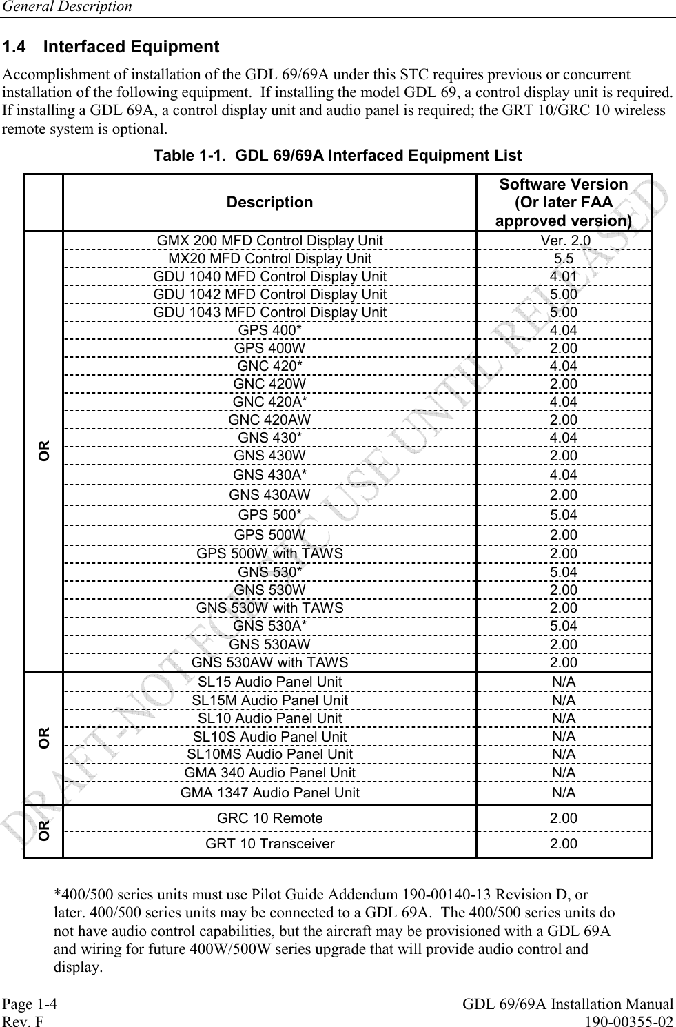
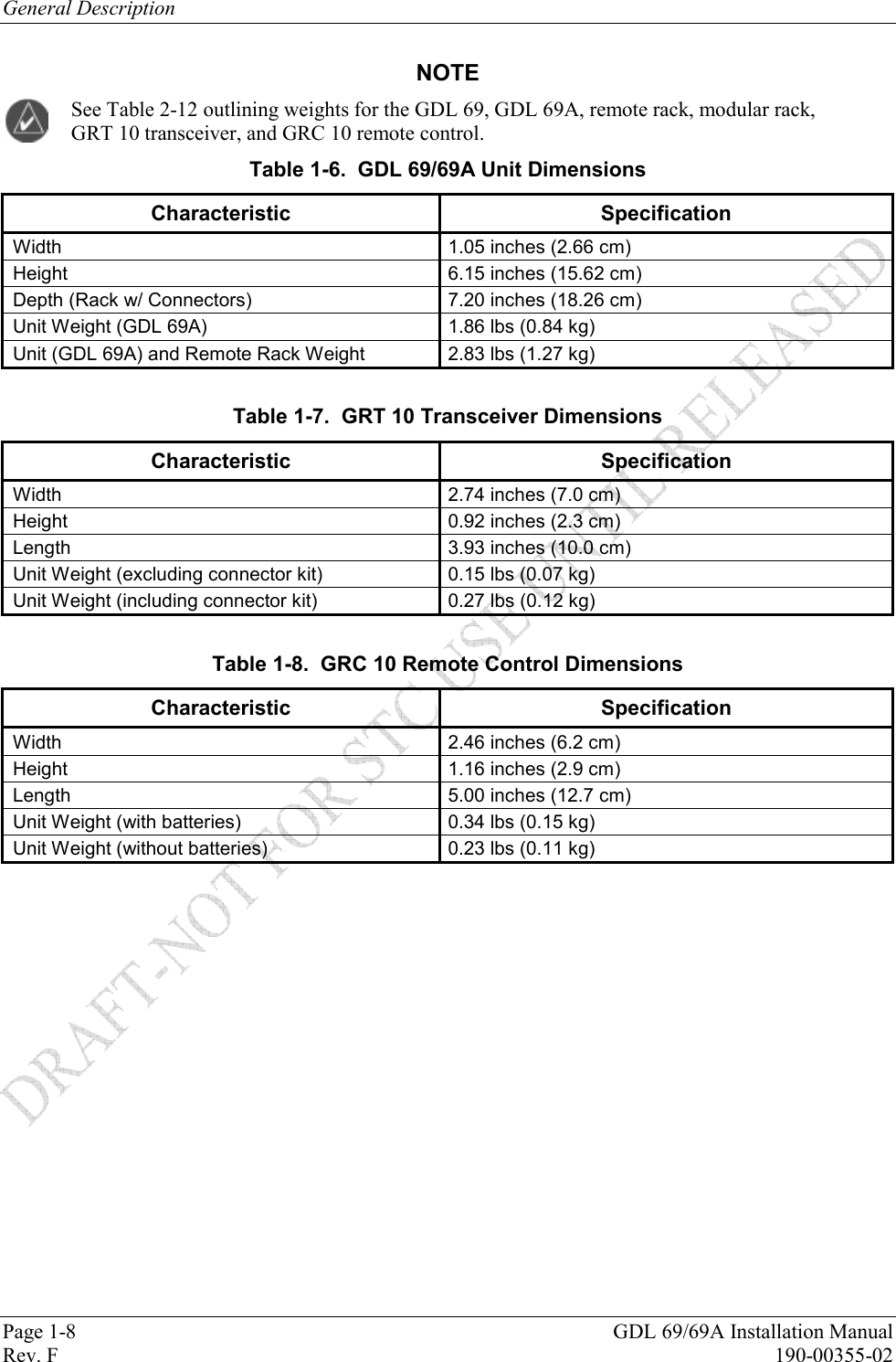
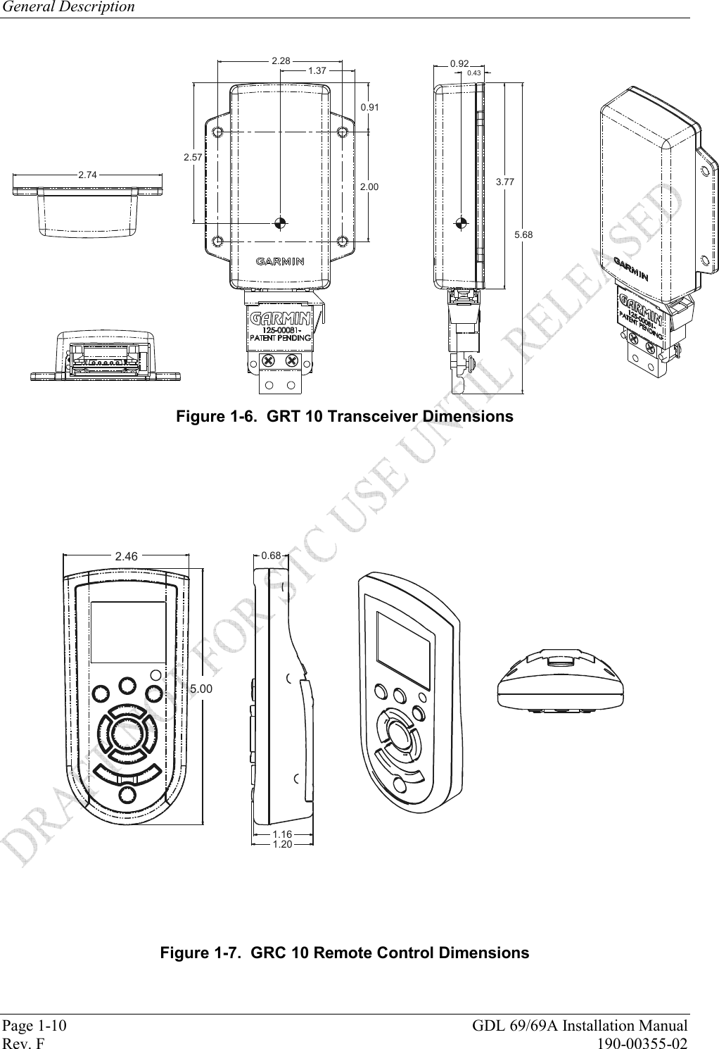
![General Description GDL 69/69A Installation Manual Page 1-9 190-00355-02 Rev. F 0.49 [12.4]8.74 [221.9]8.26 [209.8]6.91 [175.6]0.73 [18.49]4.46 [113.22]1.60 [40.53]0.37 [9.40]1.48 [37.7]ANTENNA6.43 [163.2]7.9 [200.9]3.98 [101.1]CENTER OF GRAVITY3.57 [90.7]CENTER OFGRAVITY0.73 [18.6]J1100 Figure 1-4. GDL 69/69A Remote Rack Unit Dimensions 6.30 160.07.26 184.47.65 194.38.73 221.84.30 109.23.00 76.26.90 175.3TYP.36 TYP9.1.48 TYP12.21.20 30.5WITHOUT DIMPLES1.23 31.1WITH DIMPLES.60 15.2.48 TYP12.2.36 TYP9.14X .38 9.64X 3.73 94.7J10001ANTENNA Figure 1-5. GDL 69/69A Modular Rack Unit Dimensions](https://usermanual.wiki/Garmin/01178.Install-Manual-Sect-1/User-Guide-905307-Page-9.png)