Garmin 01178 Remote Control User Manual 190 00355 02 0F

Garmin International Inc Remote Control 190 00355 02 0F

Install Manual Sect 3 and 4
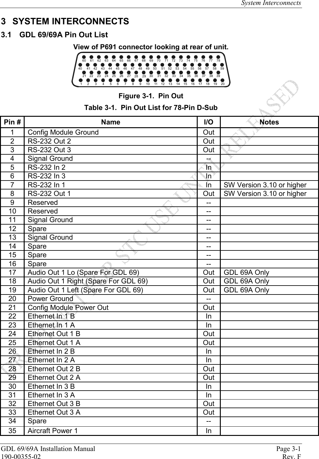
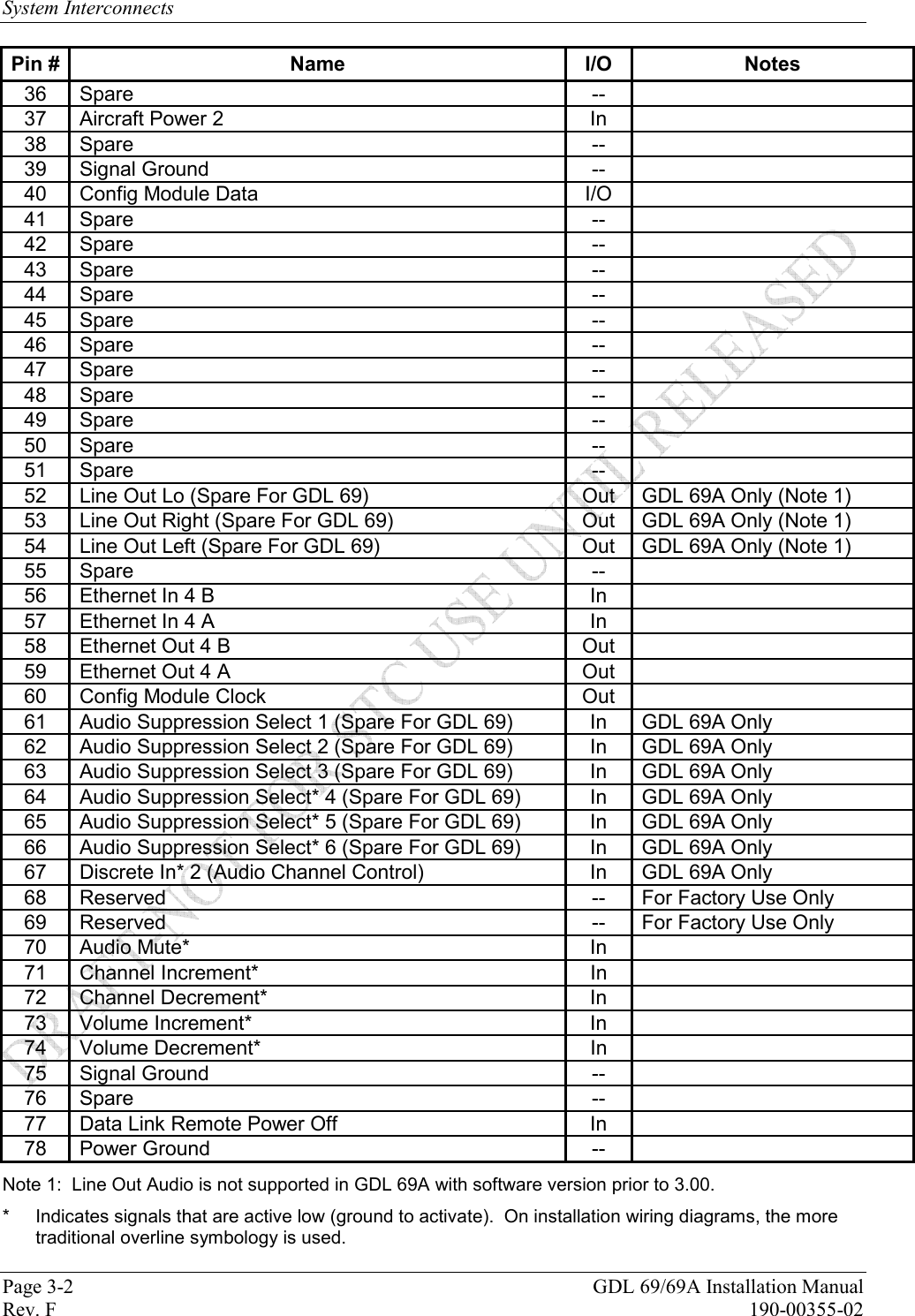
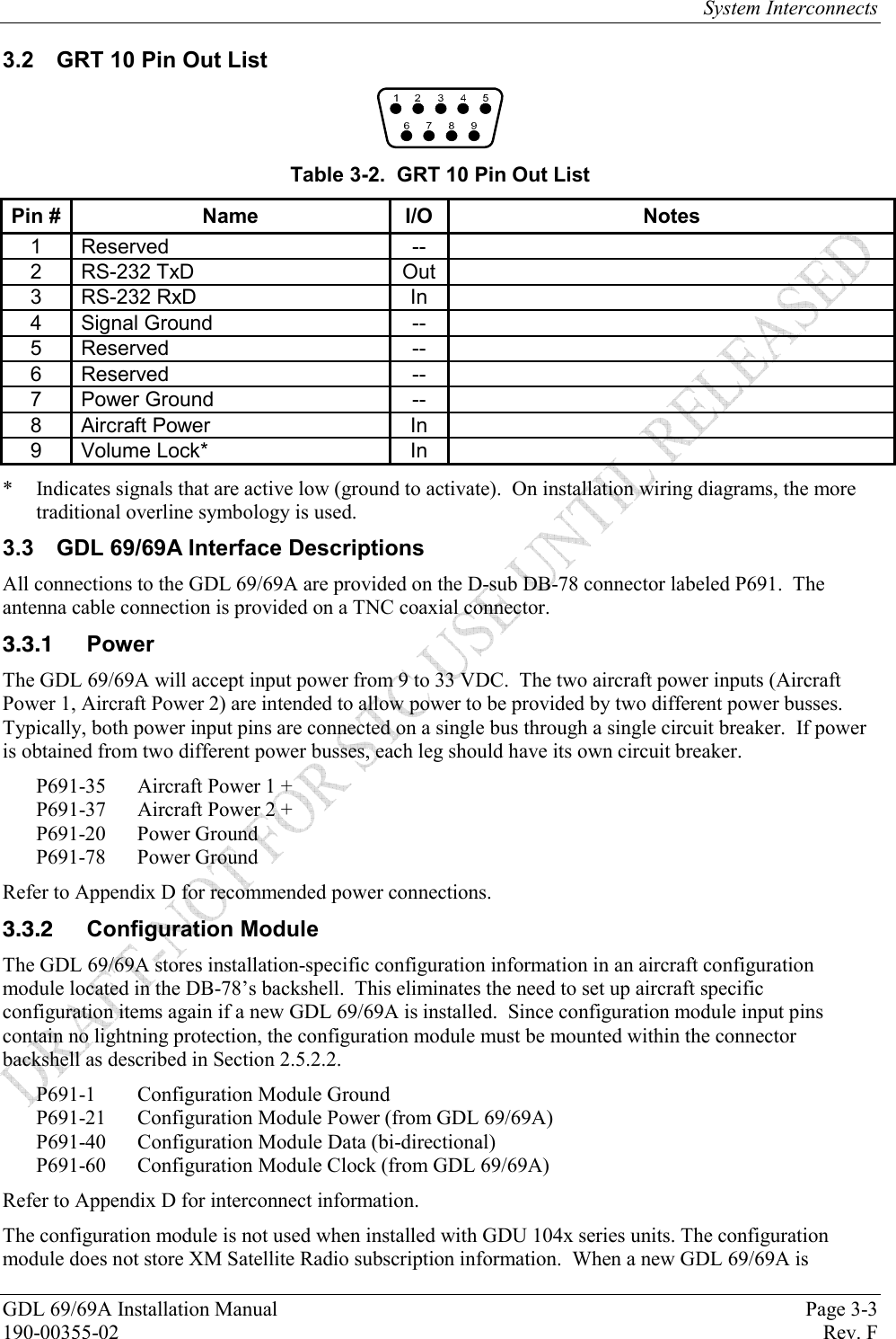
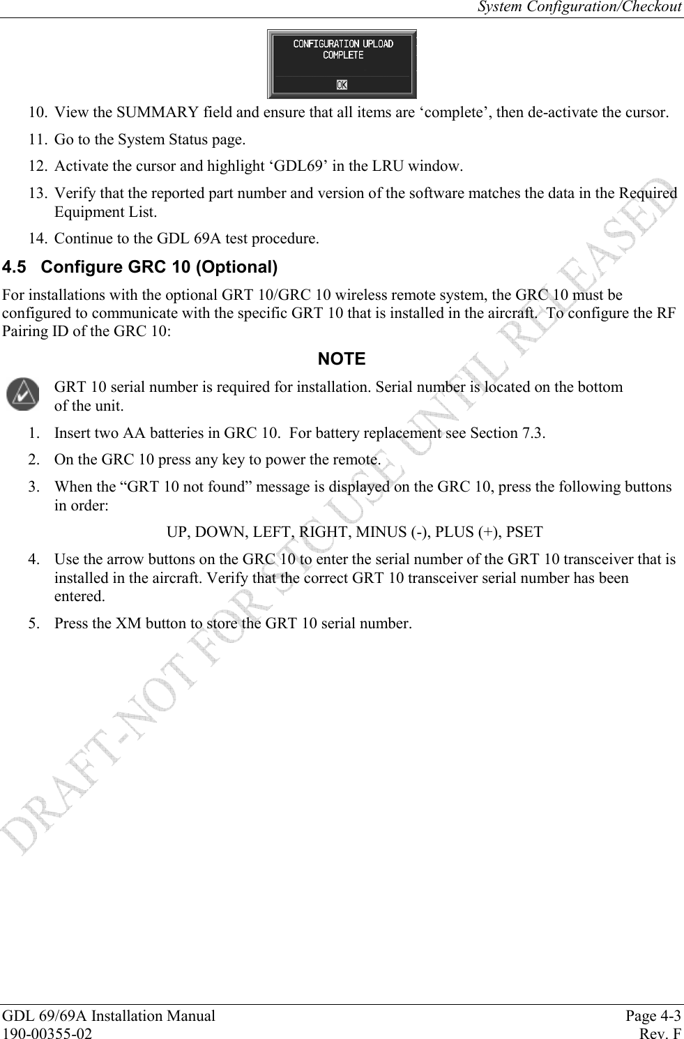
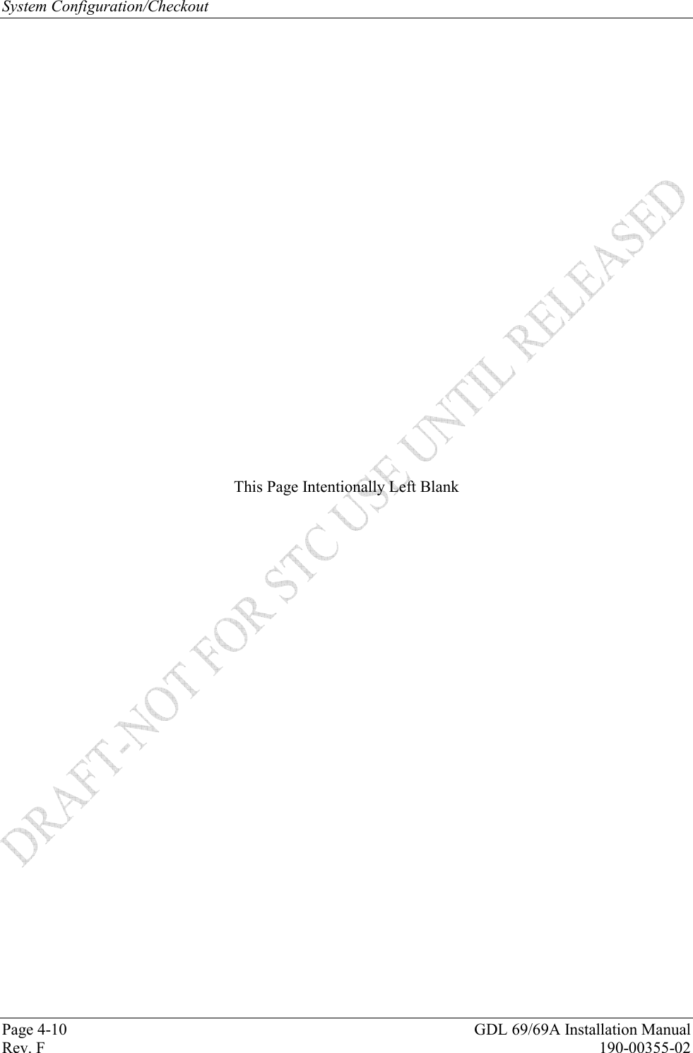
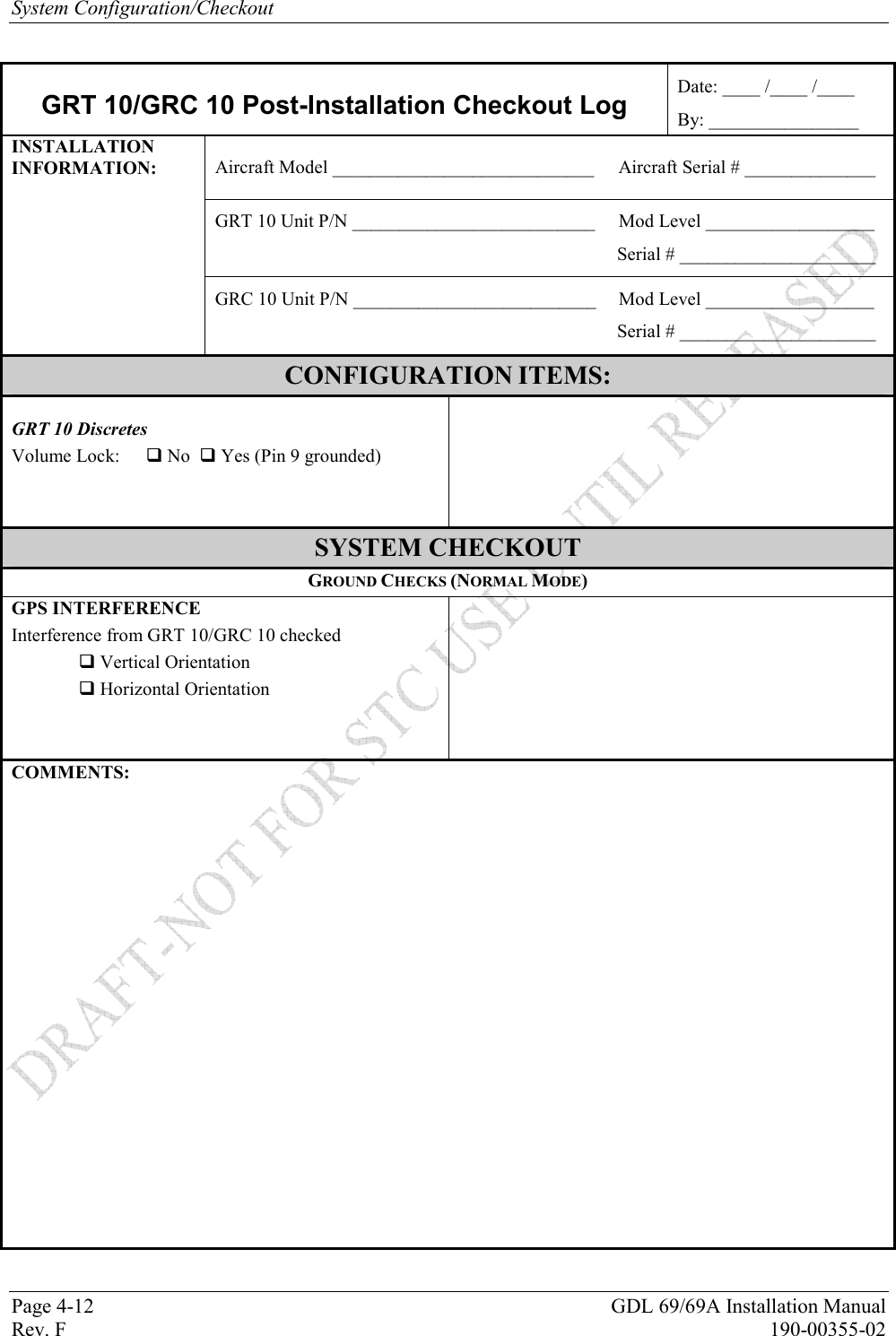
System Interconnects GDL 69/69A Installation Manual  Page 3-1 190-00355-02   Rev. F 3 SYSTEM INTERCONNECTS 3.1  GDL 69/69A Pin Out List View of P691 connector looking at rear of unit. 1 2 3 4 5 6 7 8 9 10 1112131415161718192021 22 23 24 25 26 27 28 29 30 31 32 33 34 35 36 37 38 3940 41 42 43 44 45 46 47 48 49 50 51 52 53 54 55 56 57 58 5960 61 62 63 64 65 66 67 68 69 70 71 72 73 74 75 76 77 78 Figure 3-1.  Pin Out Table 3-1.  Pin Out List for 78-Pin D-Sub Pin #  Name  I/O  Notes 1  Config Module Ground  Out   2  RS-232 Out 2  Out   3  RS-232 Out 3  Out   4 Signal Ground  --  5  RS-232 In 2  In   6  RS-232 In 3  In  7  RS-232 In 1  In SW Version 3.10 or higher 8  RS-232 Out 1  Out  SW Version 3.10 or higher 9 Reserved  --  10 Reserved  --  11 Signal Ground  --   12 Spare  --   13 Signal Ground  --   14 Spare  --   15 Spare  --   16 Spare  --   17  Audio Out 1 Lo (Spare For GDL 69)  Out GDL 69A Only  18  Audio Out 1 Right (Spare For GDL 69)  Out GDL 69A Only 19  Audio Out 1 Left (Spare For GDL 69)  Out GDL 69A Only 20 Power Ground  --   21  Config Module Power Out  Out   22  Ethernet In 1 B  In  23  Ethernet In 1 A  In  24  Ethernet Out 1 B  Out  25  Ethernet Out 1 A  Out  26  Ethernet In 2 B  In  27  Ethernet In 2 A  In  28  Ethernet Out 2 B  Out  29  Ethernet Out 2 A  Out  30  Ethernet In 3 B  In  31  Ethernet In 3 A  In  32  Ethernet Out 3 B  Out  33  Ethernet Out 3 A  Out  34 Spare  --   35  Aircraft Power 1  In
System Interconnects Page 3-2  GDL 69/69A Installation Manual Rev. F  190-00355-02 Pin #  Name  I/O  Notes 36 Spare  --  37  Aircraft Power 2  In  38 Spare  --  39 Signal Ground  --   40  Config Module Data  I/O   41 Spare  --   42 Spare  --   43 Spare  --   44 Spare  --   45 Spare  --   46 Spare  --   47 Spare  --   48 Spare  --   49 Spare  --   50 Spare  --   51 Spare  --   52  Line Out Lo (Spare For GDL 69)  Out GDL 69A Only (Note 1) 53  Line Out Right (Spare For GDL 69)  Out GDL 69A Only (Note 1) 54  Line Out Left (Spare For GDL 69)  Out GDL 69A Only (Note 1) 55 Spare  --   56  Ethernet In 4 B  In  57  Ethernet In 4 A  In  58  Ethernet Out 4 B  Out  59  Ethernet Out 4 A  Out  60  Config Module Clock  Out   61  Audio Suppression Select 1 (Spare For GDL 69)  In  GDL 69A Only 62  Audio Suppression Select 2 (Spare For GDL 69)  In  GDL 69A Only 63  Audio Suppression Select 3 (Spare For GDL 69)  In  GDL 69A Only 64  Audio Suppression Select* 4 (Spare For GDL 69)  In  GDL 69A Only 65  Audio Suppression Select* 5 (Spare For GDL 69)  In  GDL 69A Only 66  Audio Suppression Select* 6 (Spare For GDL 69)  In  GDL 69A Only 67  Discrete In* 2 (Audio Channel Control)  In GDL 69A Only 68 Reserved  -- For Factory Use Only 69  Reserved  --  For Factory Use Only 70 Audio Mute*  In  71 Channel Increment*  In  72 Channel Decrement*  In  73 Volume Increment*  In  74 Volume Decrement*  In  75 Signal Ground  --   76 Spare  --   77  Data Link Remote Power Off  In  78 Power Ground    --  Note 1:  Line Out Audio is not supported in GDL 69A with software version prior to 3.00. *  Indicates signals that are active low (ground to activate).  On installation wiring diagrams, the more traditional overline symbology is used.
System Interconnects GDL 69/69A Installation Manual  Page 3-3 190-00355-02   Rev. F 3.2  GRT 10 Pin Out List  Table 3-2.  GRT 10 Pin Out List Pin #  Name  I/O  Notes 1 Reserved  --  2 RS-232 TxD  Out  3 RS-232 RxD  In  4 Signal Ground  --  5 Reserved  --  6 Reserved  --  7 Power Ground  --  8 Aircraft Power  In  9 Volume Lock*  In  *  Indicates signals that are active low (ground to activate).  On installation wiring diagrams, the more traditional overline symbology is used. 3.3  GDL 69/69A Interface Descriptions All connections to the GDL 69/69A are provided on the D-sub DB-78 connector labeled P691.  The antenna cable connection is provided on a TNC coaxial connector.  Power The GDL 69/69A will accept input power from 9 to 33 VDC.  The two aircraft power inputs (Aircraft Power 1, Aircraft Power 2) are intended to allow power to be provided by two different power busses.  Typically, both power input pins are connected on a single bus through a single circuit breaker.  If power is obtained from two different power busses, each leg should have its own circuit breaker. P691-35  Aircraft Power 1 + P691-37  Aircraft Power 2 + P691-20 Power Ground P691-78 Power Ground Refer to Appendix D for recommended power connections.  Configuration Module The GDL 69/69A stores installation-specific configuration information in an aircraft configuration module located in the DB-78’s backshell.  This eliminates the need to set up aircraft specific configuration items again if a new GDL 69/69A is installed.  Since configuration module input pins contain no lightning protection, the configuration module must be mounted within the connector backshell as described in Section 2.5.2.2. P691-1  Configuration Module Ground P691-21  Configuration Module Power (from GDL 69/69A) P691-40  Configuration Module Data (bi-directional) P691-60  Configuration Module Clock (from GDL 69/69A) Refer to Appendix D for interconnect information. The configuration module is not used when installed with GDU 104x series units. The configuration module does not store XM Satellite Radio subscription information.  When a new GDL 69/69A is
System Interconnects Page 3-4  GDL 69/69A Installation Manual Rev. F  190-00355-02 installed in the aircraft, contact XM Satellite Radio to update the radio IDs on the current subscription or start a new subscription.     RS-232 Ports (Qty 3) Three RS-232 ports are available and can be used to connect the GDL 69/69A to control/display devices (e.g., the MX20 or GMX 200).  Support for Port 1 was enabled with software version 3.10. P691-2  Port 2 TX (out) P691-3  Port 3 TX (out) P691-4 Signal Ground P691-5  Port 2 RX (in) P691-6  Port 3 RX (in) P691-7  Port 1 RX (in)  P691-8  Port 1 TX (out)  P691-11 Signal Ground P691-13 Signal Ground NOTE In order for a serial port to function correctly, the baud rate of the RX and TX channels on a given RS-232 port must be the same.  This must be considered when assigning serial ports to interfacing equipment.   Ethernet Ports (Qty 4) Four Ethernet ports are provided. All four ports are set up to a connection speed of 10 Mb/s and can be used to transmit weather data to the display.  PORT 1 P691-22 Ethernet Receiver input Ch1-B P691-23 Ethernet Receiver input Ch1-A P691-24 Ethernet Receiver output Ch1-B P691-25 Ethernet Receiver output Ch1-A PORT 2 P691-26 Ethernet Receiver input Ch2-B P691-27 Ethernet Receiver input Ch2-A P691-28 Ethernet Receiver output Ch2-B P691-29 Ethernet Receiver output Ch2-A PORT 3 P691-30 Ethernet Receiver input Ch3-B P691-31 Ethernet Receiver input Ch3-A P691-32 Ethernet Receiver output Ch3-B P691-33 Ethernet Receiver output Ch3-A PORT 4 P691-56 Ethernet Receiver input Ch4-B P691-57 Ethernet Receiver input Ch4-A P691-58 Ethernet Receiver output Ch4-B P691-59 Ethernet Receiver output Ch4-A
System Interconnects GDL 69/69A Installation Manual  Page 3-5 190-00355-02   Rev. F   Discrete Inputs (GDL 69A Only) The discrete inputs are used to control the XM radio channels and volume. All of these inputs are active low (i.e. grounded when active, and open otherwise).  Each input presents a load of greater than 10 k. 3.3.5.1  Audio Volume Inputs (Up, Down, Mute) The Up, Down, and Mute discrete provides audio volume control of the audio output. (Note: The volume and mute controls have no affect on the Line Out output volume.) P691-73 Volume Increment P691-74 Volume Decrement P691-70 Audio Mute 3.3.5.2  Audio Channel Control Inputs (Up, Down) P691-71 Channel Increment P691-72 Channel Decrement Or If Discrete 2 (P691-67) is grounded, P691-71  Preset/Favorite Channel Increment P691-72  Preset/Favorite Channel Decrement 3.3.5.3  Audio Channel Control Option Discrete Discrete 2 is used to determine how the audio channel control inputs function.  See Section 3.3.5.2. P691-67 Discrete 2 3.3.5.4  Audio Suppression Inputs There are six discrete inputs for audio suppression. There are three active low and three active high inputs. The Audio Suppression inputs suppress the Audio Out output by activating any one of multiple inputs. The threshold voltages are as follows: Active HIGH discrete inputs: Input will go active with input voltages above 8.5V Active LOW discrete inputs: Input will go active with input voltages below 5.0V P691-61 Active HIGH discrete input P691-62 Active HIGH discrete input P691-63 Active HIGH discrete input P691-64 Active LOW discrete input P691-65 Active LOW discrete input P691-66 Active LOW discrete input 3.3.5.5 Other Discrete Inputs (Not Used) The following discrete input pins are reserved for factory use. P691-68 Discrete 1 P691-69 Test Enable   Remote Power ON/OFF Input The unit will turn off if this input is pulled above 3 volts. The unit will turn ON if the input is left floating or grounded. The input presents a load of greater than 100 k. P691-77  Data Link Remote power off
System Interconnects Page 3-6  GDL 69/69A Installation Manual Rev. F  190-00355-02   Audio Out (GDL 69A Only) The Audio Out provides stereo output for XM radio to be interconnected to an audio panel.  The Audio Out is affected by the volume controls, mute function, and suppression inputs. See Limitations Section 6.2 for requirements on use of suppression inputs. P691-17  Audio Out Lo. This is the common ground for the audio output P691-18  Audio Out Right. This is the right channel audio P691-19  Audio Out Left. This is the left channel audio   Line Out (GDL 69A Only) The Line Out output is always at a fixed output. The Line Out is not affected by the volume controls, mute function, and suppression inputs. Support for Line Out was enabled with software version 3.00. P691-52  Line Out Lo.  This is the common ground for the Line Out audio output P691-53  Line Out Right.  This is the right channel audio P691-54  Line Out Left.  This is the left channel audio  Reserved Pins These pins are reserved and should not be connected. P691-9 P691-10  Spare Pins The following pins are spare pins and not connected inside the GDL 69/69A.  Wires should not be routed to these pins as they may be used in future configurations of the GDL 69/69A.  Use of these pins may result in unintended behavior. P691-12 P691-44 P691-14 P691-45 P691-15 P691-46 P691-16 P691-47 P691-34 P691-48 P691-36 P691-49 P691-38 P691-50 P691-41 P691-51 P691-42 P691-55 P691-43 P691-76 3.4  GRT 10 Interface Descriptions All connections to the GRT 10 are provided on the 9-pin D-Sub connector.  Power The GRT 10 accepts input power from 9 to 33 VDC. The power input pins are connected to the aircraft power bus through a single circuit breaker. Pin 8  Aircraft Power + Pin 7  Power Ground Refer to Appendix D for recommended power connections.
System Interconnects GDL 69/69A Installation Manual  Page 3-7 190-00355-02   Rev. F   RS-232 Port (Qty 1) One RS-232 port is used to connect the GRT 10 to GDL 69A. Pin 2  TX (out) Pin 3  RX (in) Pin 4  Signal Ground  Volume Lock The volume lock discrete input is used to disable the volume controls of the GRC 10 remote control. When this input is active low (i.e. grounded when active, and open otherwise), the volume up, volume down and mute features of the GRC 10 are disabled; all other features of the GRC 10 remain functional. Each input presents a load of greater than 10 k . Pin 9  Volume Lock  Reserved Pins These pins are reserved and should not be connected. Pin 1 Pin 5 Pin 6
System Interconnects Page 3-8  GDL 69/69A Installation Manual Rev. F  190-00355-02                      This Page Intentionally Left Blank
System Configuration/Checkout GDL 69/69A Installation Manual  Page 4-1 190-00355-02   Rev. F 4  SYSTEM CONFIGURATION AND CHECKOUT Once the GDL 69/69A and optional GRT 10 have been installed, configure the units for the particular installation and then complete the checkout procedures herein to verify proper operation.  The steps that are not applicable to a particular installation may be ignored. A checkout log sheet is included at the end of this section.  It is to be filled out during the checkout procedure.  The completed checkout log sheet(s) should be maintained with the aircraft permanent records. 4.1  Post Installation Power Check Move the aircraft outside and ensure that there is an unobstructed view of the Southern sky.  Attach a ground power cart to the external power connector on the aircraft and apply power. NOTE Use of an external power cart is optional in order to prevent the aircraft battery from discharging to a critically low level. Power on all systems and allow two to four minutes for initialization.  Verify that the control/display unit and the audio panel are connected and operating properly.  Ensure the circuit breaker for the GDL 69/69A and GRT 10 (if installed) is closed and the Remote Power Discrete (if wired), is enabled. 4.2  Configure RS-232 Port For installations with the MX20 or GMX 200, refer to the corresponding installation manual for configuring the correct RS-232 port of the MX20 or GMX 200 that the GDL 69/69A is connected. For installations with the 400/500 and 400W/500W series units, refer to the 400/500 Series Pilot’s Guide Addendum or the 400W/500W Series Pilot’s Guides for configuring the correct RS-232 port of the 400/500 or 400W/500W series unit that the GDL 69/69A is connected. 4.3  Configure Ethernet Port For installations with the GDU 104x, refer to the GDU 104x installation manual, P/N 190-00303-01, for configuring the GDL 69/69A Ethernet ports. 4.4 Initialization of Configuration Module The GDL 69/69A requires aircraft installation information to be stored in the configuration module.  For GMX 200, MX20, 400/500 Series units, and 400W/500W Series units the configuration module is installed in the back panel connector backshell assembly and the only parameter stored in the configuration module is the variable attenuator value needed to obtain the required GDL 69/69A gain/loss component. For installations with the GDU 104x, the configuration information is stored with the G1000 avionics system, therefore the configuration module is not installed in the GDL 69/69A connector backshell. For installations with the G1000 avionics system, the configuration information contains the variable attenuator value and may contain several other parameters. NOTE The GDL 69/69A does not provide proper operation until the configuration initialization procedure is completed.    Configuration Module Procedure for Installation with MX20 and GMX 200 Refer to the latest revision of the MX20 or GMX 200 Installation Manual (Garmin AT Part Number 560-1025-(  ) and 190-00607-04) for instructions.
System Configuration/Checkout Page 4-2  GDL 69/69A Installation Manual Rev. F  190-00355-02   Configuration Module Procedure for Installation with 400/500 and 400W/500W Series Perform the following steps to program the configuration module of the GDL 69/69A when using the 400/500 Series or 400W/500W Series as the control and display unit: 1. Power up the 400/500 or 400W/500W in Configuration Mode (refer to the 400/500 or 400W/500W Install Manual for instructions) 2. Go to GDL CONFIG Page 3. Enter in the Attenuation value, which is computed as in the following formula: Attenuation = ( 6 – GLcomp )*10 GLcomp = GDL 69/69A gain/loss component value from Table 2-11. Example: If GLcomp from Table 2-11 is -1.39dB (calculated from example in Section 2.6.4.2) than;  Attenuation  = (6 - (-1.39))*10 = (6+1.39)* 10 Attenuation  = 7.39 * 10 = 73.9 rounded up 74 to enter in the 400/500 Series or 400W/500W Series. NOTE If attenuation from the above calculation is < zero or > 100 then the gain/loss compensation is outside the range required for proper operation. Review Section 2.6.4.2 for appropriate corrective action.   Configuration Module Procedure for GDU 104x 1. Insert the correct Loader Card into the top slot of the PFD. 2. Start the G1000 system in Configuration mode. 3. On the PFD, go to the Configuration Upload page using the FMS knob. 4. Activate the cursor and use the small FMS knob to highlight the airframe type in the FILE field.   NOTE Ensure that the correct airframe type is selected before proceeding; otherwise, incorrect configuration information will be loaded. 5. Press the ENT key to select the appropriate airframe type.  Once an airframe type is selected the configuration files in the SECTION field will be displayed. 6. Using the FMS knob, highlight ‘GDL69’ in the FILE LIST field.   7. Press the LOAD softkey.   8. Select YES and press the ENT key to acknowledge the following prompt:  9. Monitor the status of the upload.  When the upload is finished, press the ENT key to acknowledge the following confirmation:
System Configuration/Checkout GDL 69/69A Installation Manual  Page 4-3 190-00355-02   Rev. F  10. View the SUMMARY field and ensure that all items are ‘complete’, then de-activate the cursor. 11. Go to the System Status page. 12. Activate the cursor and highlight ‘GDL69’ in the LRU window. 13. Verify that the reported part number and version of the software matches the data in the Required Equipment List. 14. Continue to the GDL 69A test procedure. 4.5  Configure GRC 10 (Optional) For installations with the optional GRT 10/GRC 10 wireless remote system, the GRC 10 must be configured to communicate with the specific GRT 10 that is installed in the aircraft.  To configure the RF Pairing ID of the GRC 10: NOTE GRT 10 serial number is required for installation. Serial number is located on the bottom of the unit. 1. Insert two AA batteries in GRC 10.  For battery replacement see Section 7.3. 2. On the GRC 10 press any key to power the remote. 3. When the “GRT 10 not found” message is displayed on the GRC 10, press the following buttons in order:   UP, DOWN, LEFT, RIGHT, MINUS (-), PLUS (+), PSET 4.  Use the arrow buttons on the GRC 10 to enter the serial number of the GRT 10 transceiver that is installed in the aircraft. Verify that the correct GRT 10 transceiver serial number has been entered. 5.  Press the XM button to store the GRT 10 serial number.
System Configuration/Checkout Page 4-4  GDL 69/69A Installation Manual Rev. F  190-00355-02 4.6 System Operational Checkout Before performing system checkout, ensure that the configuration module (if applicable) is properly programmed and the GDL 69/69A connected to the correct communication port.     Data Link Status and Connection Power up the GDL 69/69A. View the data link status on the display/control device to verify XM signals are being received. Refer to the MX20 installation manual, GMX 200 installation manual, 400W/500W Series Pilot’s Guide or the 400/500 Series Pilot’s Guide Addendum for instructions on how to access the data link status page on those units. For GDU 104x units, refer to the G1000 Configuration Manual, 190-00303-04 or the aircraft specific configuration manual. The antenna gain setting should be 25 for the GA 37, GA 55, and GA 55A, and may be different for equivalent antennas. The cable loss setting should be set to 4.5 dB at the factory.  Set this setting to the value computed in Section 2.6.4.1 if it is different from the default value.     Figure 4-1.  Data Link Configuration Page on the MX20  Figure 4-2. Data Line Configuration Page on the GMX 200
System Configuration/Checkout GDL 69/69A Installation Manual  Page 4-5 190-00355-02   Rev. F     Figure 4-3.  Data Link Configuration Page on the 400/500 Series (500 Series shown, 400 Series screen is similar)    Figure 4-4.  Data Link Configuration Page on the 400W/500W Series (500W Series shown, 400W Series screen is similar)
System Configuration/Checkout Page 4-6  GDL 69/69A Installation Manual Rev. F  190-00355-02  Figure 4-5.  Configuration Upload Page - GDU 104x  Figure 4-6.  Configuration Page – GDU 104x
System Configuration/Checkout GDL 69/69A Installation Manual  Page 4-7 190-00355-02   Rev. F   Verifying XM Receiver Signal Strength The following check will verify the XM antenna connection to the GDL 69/69A XM Receiver.  Verify the XM signal level has a minimum of three bars.  CAUTION Make sure the aircraft is outside and that there is an unobstructed view of the Southern sky. Refer to the appropriate installation manual of the display device for instructions to view the signal status.   Audio Output (for GDL 69A connected to GMX 200, MX20, 400W/500W or GDU 104x) CAUTION If GDL 69A is connected to an audio panel, the audio input should be used. A test must be conducted to ensure COMM radio signals will mute audio output from the GDL 69A. NOTE If a GDL 69A is installed with the 400/500 series, the GDL 69A audio feature is not operational. Verify Channel 0 or other channel is displayed. The GDL 69A powers up with the audio muted. Press mute or volume keys (switch or on display/control device). Verify sound output from speakers. The GDL 69A may come with a trial activation to XM audio entertainment.  With this trial activation, all audio channels for the given subscription should be available.   Discrete Switches (for GDL 69A only, if installed) Channel Up/Down— Press the Channel Up or Down switches and observe that channel display on the display/control device increments or decrements, respectively. Volume Up/Down— Press the Volume Up or Down switches and observe that speaker volume increases or decreases, respectively. Mute—Pressing the Mute switch should terminate sound from speakers. Pressing it again should resume audio. More optional checkout procedures are available after the GDL 69/69A is activated with XM Satellite Radio Corporation.  Refer to the XM Activation Procedure document, P/N 190-00355-04.   Audio Suppression Input (GDL 69A only) The GDL 69A has audio suppression inputs to disable the audio output when an electronic aural warning, such as a stall warning or gear warning, is activated. With installations where the Audio Suppression is used, activate the Stall Warning, Gear Warning, or other interfaced inputs to the Audio Suppression inputs, one at a time. Verify the GDL 69A audio to the crew headphones is muted when each warning alarm is activated. The stall warning horn may be activated by simply raising the stall vane on the leading edge of the wing.  The gear warning horn may be simulated by providing power or ground, as appropriate, directly to the horn. This can only be done provided the horn has been tested for proper operation when a gear retraction test was performed.
System Configuration/Checkout Page 4-8  GDL 69/69A Installation Manual Rev. F  190-00355-02 4.7  GRT 10/GRC 10 Post Installation Checkout Procedures (If installed)  Functional Check 4.7.1.1 Power On/Off Turn on the GRC 10 by pressing and releasing any key.  The unit will automatically power off after a period of inactivity.  To manually turn off the unit, press the Menu key, highlight the Power Down option, and press the XM key. 4.7.1.2 Channel Controls Channel Up/Down— Press the Up or Down buttons on GRC 10 Remote Control and observe that channel display on the GRC 10 Remote Control and display/control device increments or decrements, respectively. 4.7.1.3 Volume Controls Volume Up/Down— Press the Plus (+) or Minus (-) buttons on GRC 10 Remote Control and observe that speaker volume increases or decreases, respectively. Mute—Pressing the Mute button on GRC 10 Remote Control should terminate sound from audio speakers. Pressing it again should resume audio. 4.7.1.4  Volume Controls (if Volume Lock Enabled) Verify that the lock symbol is present next to the volume indicator on the GRC 10 remote control. Volume Up/Down/Mute:  Press the Plus (+), Minus (-), and Mute buttons on the GRC 10 remote control and observe that the speaker volume does not change and that the message, “Volume Controls Locked” briefly appears on the GRC 10 display.   GRT 10/GRC 10 Software Versions The system information, which includes the GRC 10 software version, the GRT 10 software version, and the RF pairing ID that is programmed in the GRC 10, can be viewed on the GRC 10. To view the system information, press the Menu key, highlight the System Info menu selection, and press the  return to the Menu screen, press the Menu or XM key.   GPS Interference Check Check that the GRT 10/GRC 10 wireless remote system does not interfere with the existing GPS installation.  This test should be performed for each GPS unit installed in the aircraft.  Perform the test with the GRC 10 in a horizontal and vertical orientation. 1. Power on the GPS installation and view the GPS signal strength of each satellite being received.   NOTE If the unit is unable to acquire satellites, relocate the aircraft away from obstructions which might be shading GPS reception. 2. Power on the GDL 69A and GRT 10. 3. Power on the GRC 10 and verify that Channels page and Categories page are populated.  NOTE:  It may take up to 10 minutes from the time the GDL 69A is powered on for the GDL 69A to acquire this information and pass it to the GRC 10. 4. Manually power off the GRC 10.
System Configuration/Checkout GDL 69/69A Installation Manual  Page 4-9 190-00355-02   Rev. F NOTE For composite aircraft, hold the GRC 10 as close to the antenna under test as practical from inside the cabin.  For metal aircraft, hold the GRC 10 close to the window nearest the antenna under test.  Repeat the test for the other GPS antenna when complete. 5. While monitoring the signal status of each satellite being received on the GPS, power on the GRC 10 using the XM button and immediately press the  button at least once a second for a minimum of 35 seconds and check the GPS signal reception to make sure it is not affected (no significant signal degradation).  Perform the test with the GRC 10 in the horizontal orientation with the unit pointing at the antenna.  Repeat test with the GRC 10 in the vertical orientation with the back of the unit pointing at the antenna. NOTE If the GDL 69A subscription services with XM Satellite Radio Corporation have not been activated, only a limited number of channels will be available.  In this case, repeated pressing of the GRC 10  reached.  The GRC 10 is still communicating with the GRT 10 even though the channel display may not be updated. 4.8  Activation with XM Satellite Radio Before the GDL 69/69A can be used, the unit has to be activated by XM Satellite Radio and services have to be subscribed to XM Satellite Radio Corporation.  Refer to Garmin Document P/N 190-00355-04.
System Configuration/Checkout Page 4-10  GDL 69/69A Installation Manual Rev. F  190-00355-02                         This Page Intentionally Left Blank
System Configuration/Checkout GDL 69/69A Installation Manual  Page 4-11 190-00355-02   Rev. F  GDL 69/69A Post-Installation Checkout Log Date: ____ /____ /____ By: ________________ Aircraft Model ____________________________     Aircraft Serial # ______________ GDL 69/69A Unit P/N ______________________  Mod Level __________________ Serial # _____________________ INSTALLATION INFORMATION: Antenna P/N __________________________  Antenna Model _______________ Serial # _____________________ CONFIGURATION ITEMS: GDL 69/69A Installations  GDL 69A Installations Only Remote Power Discrete   Audio Output   Line Output  Enabled   N/A Device ____________  Device ____________   RS-232 Serial Interface Ethernet Ports Audio Suppression Input  Audio/Channel Control Port 1 Device ___________ Port 1 Device __________ #1 N/A  Active ______  Volume Control    N/A  Port 2 Device ___________ Port 2 Device __________ #2 N/A  Active ______  Volume Mute        N/A Port 3 Device ___________  Port 3 Device __________  #3 N/A  Active ______   Channel Control   N/A   Port 4 Device __________  #4 N/A  Active ______   Preset Option        N/A   Gain/Loss (GLcomp) Value   #5 N/A  Active ______   Calculated Value ________    #6 N/A  Active ______   SYSTEM CHECKOUT GROUND CHECKS (NORMAL MODE) INTERFERENCE CHECKOUT AUDIO CHECKOUT (GDL 69A ONLY)  [ N/A] Serial Interference to Display Devices checked   [ N/A] Line Output checked  [ N/A] Ethernet Interference to Display Devices checked  [ N/A] Audio Output checked   Configuration Module (GLcomp) checked   [ N/A] Channel Control checked   XM Signal Reception checked   [ N/A] Volume Control checked   [ N/A] Audio Mute Control checked   [ N/A] Audio Suppression checked   [ N/A] GRC/GRT Device checked COMMENTS:
System Configuration/Checkout Page 4-12  GDL 69/69A Installation Manual Rev. F  190-00355-02  GRT 10/GRC 10 Post-Installation Checkout Log Date: ____ /____ /____ By: ________________ Aircraft Model ____________________________  Aircraft Serial # ______________ GRT 10 Unit P/N __________________________  Mod Level __________________ Serial # _____________________ INSTALLATION INFORMATION: GRC 10 Unit P/N __________________________  Mod Level __________________ Serial # _____________________ CONFIGURATION ITEMS:   GRT 10 Discretes  Volume Lock:    No   Yes (Pin 9 grounded)        SYSTEM CHECKOUT GROUND CHECKS (NORMAL MODE) GPS INTERFERENCE  Interference from GRT 10/GRC 10 checked    Vertical Orientation    Horizontal Orientation       COMMENTS:

Navigation menu