Garmin 01443 LICENSED NON-BROADCAST AERONAUTICAL TRANSMITTER User Manual 190 00926 01 0A
Garmin International Inc LICENSED NON-BROADCAST AERONAUTICAL TRANSMITTER 190 00926 01 0A
UserManual.wiki
>
Garmin
>
01443 User Manual
Users Manual
Navigation menu
Upload a User Manual
Namespaces
Wiki Guide
HTML
PDF
Info
Views
User Manual
Discussion / Help
Navigation


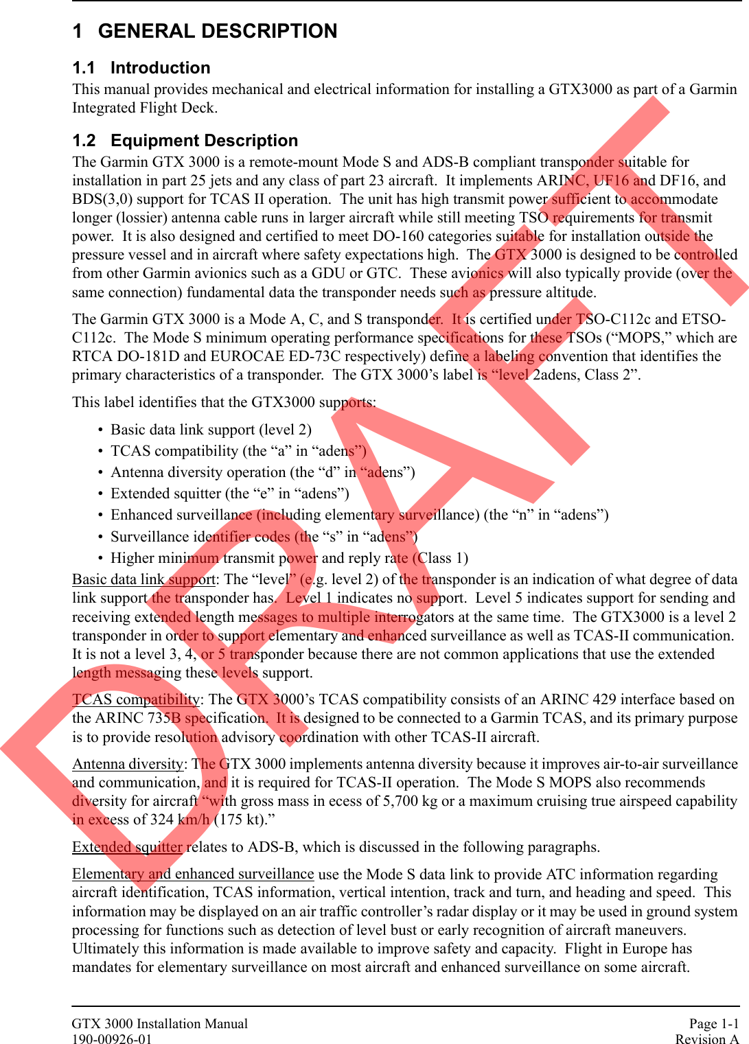

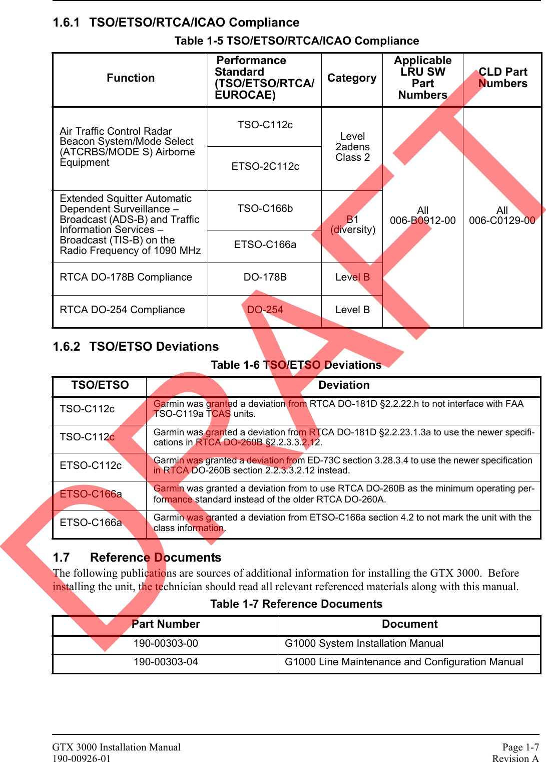
![GTX 3000 Installation Manual Page 1-3190-00926-01 Revision A1.4 Technical Specifications1.4.1 General SpecificationsNote:1. Each unit’s external suppression is tested to the specifications above. The design based on the specifications in ARINC 718A Attachment 6 and ARINC 735A Attachment 8.Table 1-1 General SpecificationsCharacteristic SpecificationEnvironmental Qualification Form 0050-00503-01FCC Authorization Emission Designator 12M0M1DAntenna CompatibilityCompatible with any antenna certified to one of the following TSOs:TSO-C66() [DME TSO]TSO-C74() [ATCRBS TSO]TSO-C112() [Mode S TSO]Antenna Cable Requirements Cable + bulkhead connector loss @1090 MHz < 3.0 dBTransmitter Power 250 Watts minimum, 500 Watts nominalTransmitter Frequency 1090 MHz ±1 MHzReceiver Frequency 1030 MHzReceiver Sensitivity -74 dBm nominal for 90% repliesExternal Suppression Input Low ≤ 1.0 V; High ≥ 9 VExternal Suppression Output Minimum is greater than +8V into 350 Ω in parallel w/ 1800 pFMaximum is less than +36V into any loadDRAFT](https://usermanual.wiki/Garmin/01443/User-Guide-1694649-Page-11.png)


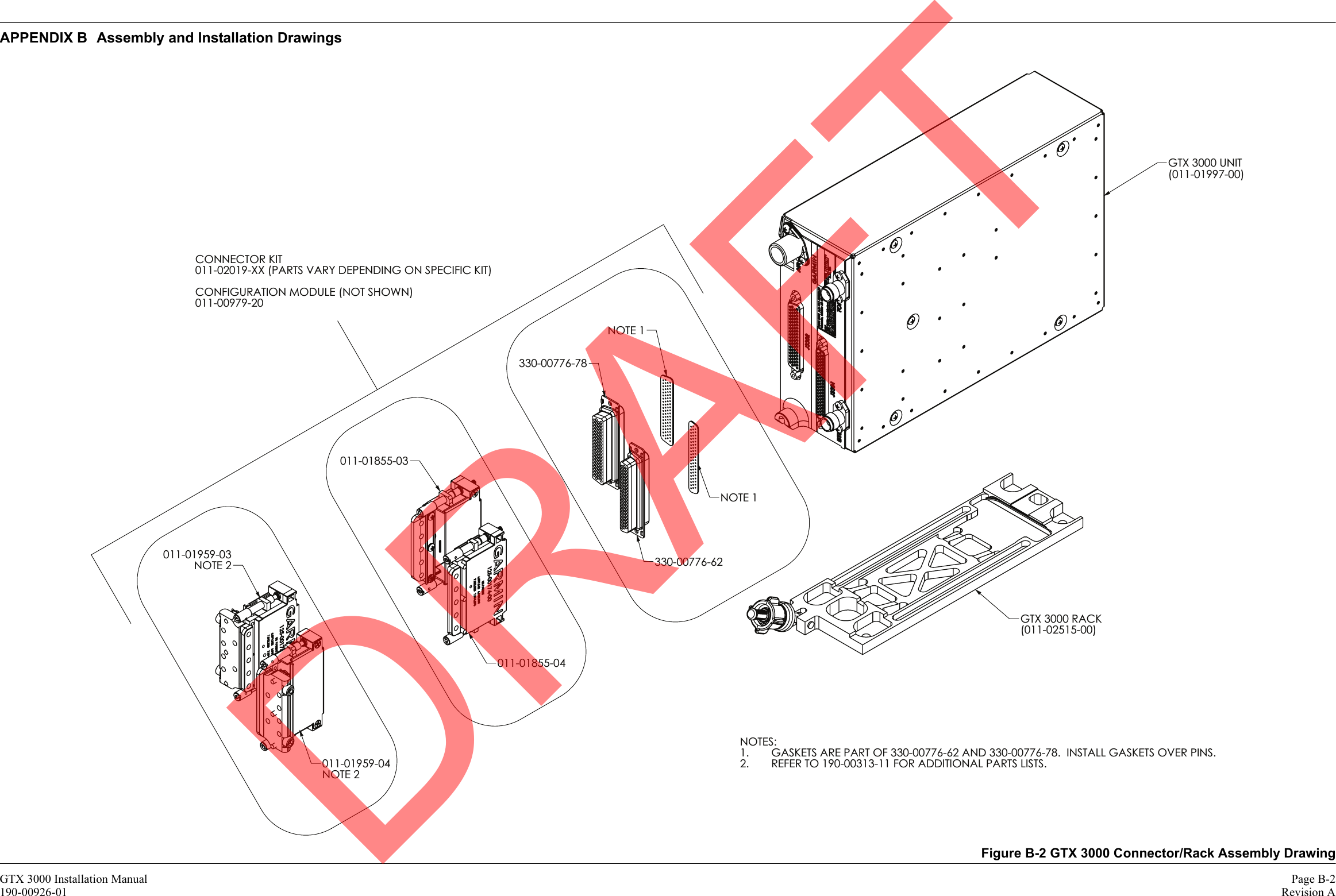
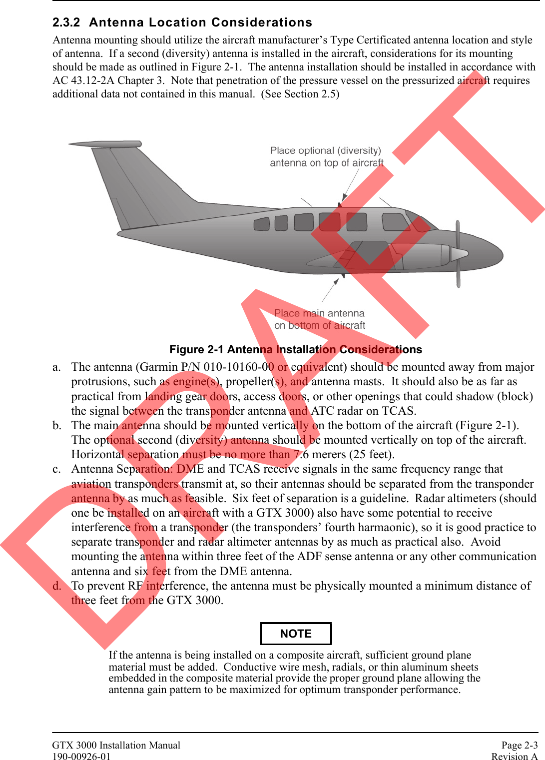
![Page 2-2 GTX 3000 Installation ManualRevision A 190-00926-012.2.2 Additional Equipment RequiredThe following installation accessories are required but not provided:• Cables – The installer will supply all system cables including circuit breakers. Cable requirements and fabrication is detailed in Section 3 of this manual.• Hardware – #6-32 x 100° Flathead SS Screw [(MS24693, AN507R or other approved fastener) (4 ea.)] for horizontal mounting of the remote stand-alone rack.• Hardware – #8-32 Panhead Machine Screw [(MS35206, AN526 or other approved fastener) (4 ea.)] for vertical mounting of the remote stand-alone rack.• Encoding altitude Digitizer – For GNS 480 (CNX80) and GMX 200 (MX20) installation. Use encoding altimeter manufacturer’s instructions. The Garmin GAE 43 (Garmin P/N 013-00066-00) can provide altitude data in either serial or parallel gray code format.2.3 Installation ConsiderationsIn a Garmin Integrated Flight Deck, the GTX 3000 interfaces with both GIA units. Optional available discrete line interfaces are shown in Section 4.5 Discrete Functions.In other system installations, the GTX 3000 can interface with equipment including altimeters and Air Data Computers (ADC). RS-232, RS-422, and ARINC 429 provide a serial communication path between interfacing equipment. Fabrication of a wiring harness is required..2.3.1 Preservation of Previous SystemsIt is the installer’s responsibility to preserve the essential characteristic of the aircraft being modified with this equipment to be in accordance with the aircraft manufacturer’s original design. This includes the preservation of multiple power buses, which reduces the probability of interrupting power to essential instruments and avionics.Table 2-4 Connector Kit, 90 Degree (011-02019-01)Item Garmin Part Number QuantityBackshell w/hardware, 90 Degree Jackscrew, 37/62 pin 011-01959-03 1Backshell w/hardware, 90 Degree Jackscrew, 50/78 pin 011-01959-04 1Teflon heat shrink tubing, .093 ID 312-00005-05 6 (cm)High density D-Sub connector, male 62 pin 330-00776-62 1High density D-Sub connector, male 78 pin 330-00776-78 1Crimp Contact Pin 22D 336-00021-00 20Crimp Contact Pin 22D, 18 & 20 AWG 336-00044-00 7DRAFT](https://usermanual.wiki/Garmin/01443/User-Guide-1694649-Page-18.png)
![Page 2-4 GTX 3000 Installation ManualRevision A 190-00926-012.4 Cabling and WiringRefer to the interconnect examples in Appendix C for wire gauge guidance.In some cases, a larger gauge wire such as AWG #18 may be needed for power connections. If using #18 barrel contacts, ensure that no two contacts are mounted directly adjacent to each other. This minimizes the risk of contacts touching and shorting to adjacent pins or to ground.Ensure that routing of the wiring does not come in contact with sources of heat, RF or EMI interference. Check that there is ample space for the cabling and mating connectors. Avoid sharp bends in cabling and routing near aircraft control cables. It is also good practice to avoid routing cables near sharp edges because aircraft vibration might wear away the insulation on the wires, which will leave them exposed to moisture and potentially create arcing or intermittent short circuits.The maximum attenuation at 1090 MHz between the unit and the antenna must not exceed 3.0 dB. This loss specification includes connector loss; for example, through a bulkhead connector (0.2 dB is typical loss for each bulkhead connector). The GTX 3000 back-plate assembly utilizes a BNC-type (bayonet connection) coaxial connector.Table 2-5 lists examples of recommended antenna cable. Use the table to determine the length of cable needed to connect the transponder to the antenna, and to look up a recommended cable manufacturer and part number that will meet the 3.0 dB loss spec. The table assumes a loss figure of 0.2 dB per connector. Note that any 50 Ω, double shielded coaxial cable assembly that meets airworthiness requirements and the 3.0 dB maximum loss figure (including connectors) may be used.Differential cable loss: If the cable loss difference between top and bottom channels is less than 1 dB, the unit’s default cable loss values are applicable, and the unit does not require cable loss configuration. If that cable loss difference is more than 1 dB different between antennas, then cable loss configuration is required..Table 2-5 Cable SpecificationsMax. Length (feet – [m])Insertion loss (dB/100ft) ECS Type MIL-C-17 Type RG Type17' 5.2" [4.40m] 18.0 M17/128-RG400 RG-40017' 11.7" [5.48m] 14.45 3C142B21' 7.8" [6.60m] 12.00 M17/112-RG304 RG-30429' 6.7" [9.01m] 8.80 311601 M17/127-RG393 RG-39336' 6.2" [11.13m] 7.12 31150147' 4.9" [14.25m] 5.56 31120171' 7.4" [21.83m] 3.63 310801Supplier InformationVendor: Electronic Cable Specialists5300 W. Franklin DriveFranklin, WI 53132Tel: 800-327-9473414-421-5300Fax: 414-421-5301www.ecsdirect.comSee current issue of Qualified Products List QPL-17.RG types are obsolete and are shown for reference only; replaced by M17 type numbers.DRAFT](https://usermanual.wiki/Garmin/01443/User-Guide-1694649-Page-20.png)
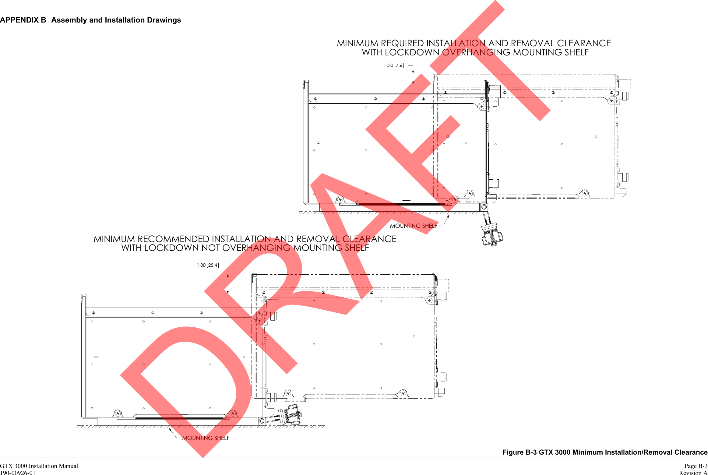
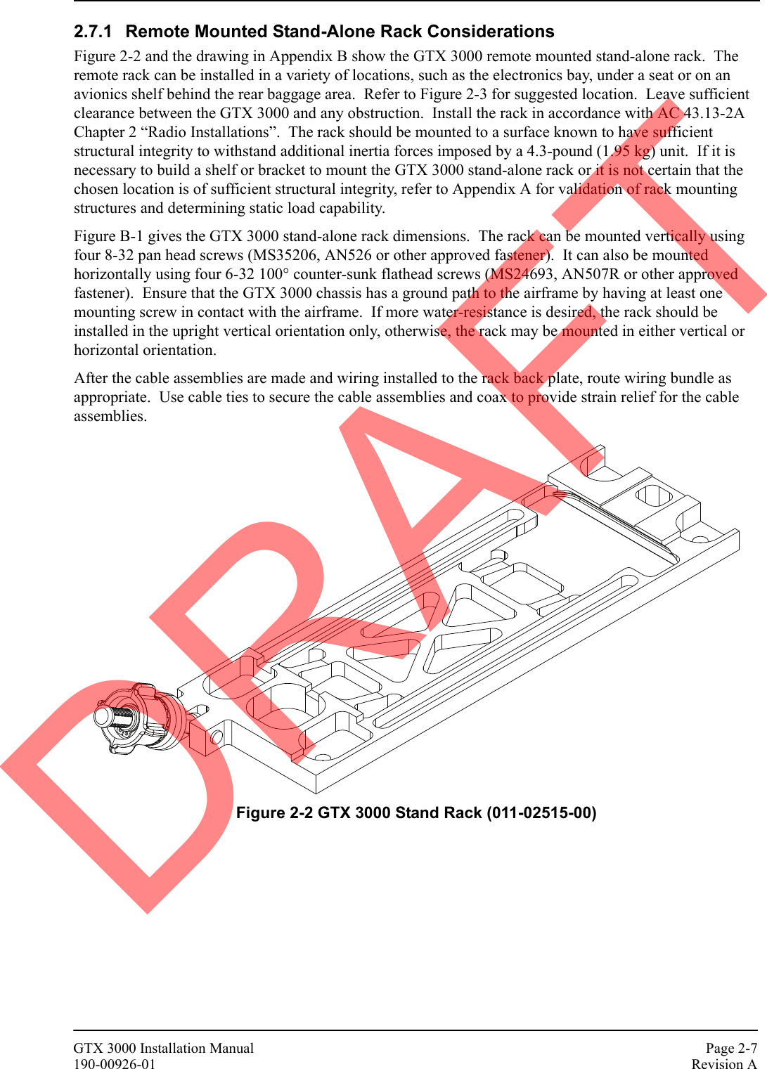
![GTX 3000 Installation Manual Page 2-5190-00926-01 Revision AThe maximum one-way propagation delay through the cables must not be more than 125 ns. The maximum difference in the one-way propagation delay between the top and bottom antenna cables must be less than or equal to 75 ns. Use Table 2-6 to determine the maximum difference in length between the top and bottom antenna cables.Absolute cable delay: Each antenna cable must have less than 75 ns of delay. The 75 ns spec is for one-way cable delay – not delay down the cable and back up it (which one might consider given the receive and transmit functions). If you meet the 3 dB cable loss requirement, you’ll almost certainly meet the 75 ns delay requirement.Differential cable delay: If the cable delay difference between the two cables is less than 25 ns, the unit does not require cable delay to be configured. The unit’s default values will suffice. Otherwise, we’ll simply have to configure each channel’s cable delay.* Maximum difference in cable length is limited by maximum cable length.2.4.1 Cable Routing ConsiderationsWhen routing cables, observe the following precautions:• All cable routing should be kept as short and as direct as practical.• Avoid sharp bends to prevent insulation from being breached.• Avoid routing close to sharp edges to prevent insulation from being breached due to vibration or handling the cable.• Avoid routing cables near power sources (e.g., 400 Hz generators, trim motors, etc.) or near power for fluorescent lighting.• Avoid routing antenna cables near DME, TCAS, radar altimeter, and ADF antenna cables (allow at least a 12-inch separation).Table 2-6 Maximum Difference in Cable LengthsMax. Difference in Length(feet – [m])Velocity of Propagation(ns/ft)ECS Type MIL-C-17 Type RG Type14' 5.2" [4.40m]* 1.46 M17/128-RG400 RG-40017' 11.7" [5.48m]* 1.46 3C142B21' 7.8" [6.60m]* 1.46 M17/112-RG304 RG-30429' 6.7" [9.01m]* 1.25 311601 M17/127-RG393 RG-39336' 6.2" [11.13m]* 1.25 31150147' 4.9" [14.25m]* 1.25 31120159' 11.7" [18.28m] 1.25 310801DRAFT](https://usermanual.wiki/Garmin/01443/User-Guide-1694649-Page-21.png)


![GTX 3000 Installation Manual Page 4-1190-00926-01 Revision A4 SYSTEM INTERCONNECTS4.1 Pin Function List4.1.1 P3301Figure 4-1 View of J3301 connector, looking at unit* Denotes Active Low (Ground to activate).Table 4-1 P3301 Pin ListPin Pin Name I/O1 RESERVED [AVIONICS MASTER ON SELECT] --2 ALTITUDE A1 In3 ALTITUDE C2 In4 ALTITUDE A2 In5 ALTITUDE A4 In6 ALTITUDE C4 In7 ALTITUDE B1 In8 ALTITUDE C1 In9 ALTITUDE B2 In10 ALTITUDE B4 In11 ALTITUDE D4 In12 EXTERNAL IDENT SELECT* In13 EXTERNAL STANDBY SELECT* In14 RESERVED [28V LIGHTING BUS HI] --15 AUDIO OUT HI Out16 AUDIO OUT LO Out17 SQUAT SWITCH IN In18 RESERVED [BOOT BLOCK SELECT] --19 ALTITUDE ALERT ANNUNCIATE* Out20 RESERVED [HIJACK MODE SELECT] --21 RESERVED [AIRCRAFT POWER 1] --22 RS-232 IN 1 In23 RS-232 OUT 1 Out24 RS-232 IN 2 In25 RS-232 OUT 2 Out26 ARINC 429 IN 3 A In27 RESERVED [POWER GROUND] --28 ARINC 429 OUT 2 B Out29 ARINC 429 IN 3 B In30 ARINC 429 OUT 2 A Out31 EXTERNAL SUPPRESSION I/O I/O123456789101112131415222324252627282930313233343536444647484950515253545556161718192021373839404142575859606162DRAFT](https://usermanual.wiki/Garmin/01443/User-Guide-1694649-Page-29.png)
![Page 4-2 GTX 3000 Installation ManualRevision A 190-00926-01 Denotes Active Low (Ground to activate).Table 4-1 P3301, Pin List continuedPin Pin Name I/O32 ARINC 429 IN 1 A In33 ARINC 429 IN 2 A In34 ARINC 429 OUT 1 B Out35 ARINC 429 IN 1 B In36 ARINC 429 IN 2 B In37 ARINC 429 OUT 1 A Out38 RESERVED [VOLTAGE TEMPERATURE PROBE OUT] --39 RESERVED [VOLTAGE TEMPERATURE PROBE IN] --40 GPS PPS IN 1 In41 CURRENT TEMPERATURE PROBE OUT Out42 RESERVED [AIRCRAFT POWER 1] --43 RESERVED [POWER GROUND] --44 CURRENT TEMPERATURE PROBE IN In45 RESERVED [14V/5V LIGHTING BUS HI] --46 TIS CONNECT SELECT* In47 AUDIO MUTE SELECT* In48 ARINC 429 IN 4 A In49 ARINC 429 IN 4 B In50 ALTITUDE COMMON (GROUND) In51 RESERVED [SIGNAL GROUND] --52 GPS PPS IN 2 HI In53 GPS PPS IN 2 LO In54 RESERVED [XPDR REMOTE POWER OFF] --55 SPARE --56 RESERVED [AIRCRAFT POWER 2] --57 SPARE --58 RESERVED [SIGNAL GROUND] --59 SPARE --60 RESERVED [AIRCRAFT POWER 2] --61 XPDR FAIL* OUT 1 Out62 RESERVED [SWITCHED POWER OUT] --DRAFT](https://usermanual.wiki/Garmin/01443/User-Guide-1694649-Page-30.png)
![GTX 3000 Installation Manual Page 4-3190-00926-01 Revision A4.1.2 P3302Figure 4-2 View of J3302 connector, looking at unit*Denotes Active Low (Ground to activate).Table 4-2 P3302 Pin ListPin Pin Name I/O1 CONFIG MODULE GROUND --2 RESERVED [SIGNAL GROUND] --3 AIRCRAFT POWER 1 In4 RESERVED [SIGNAL GROUND] --5 AIRCRAFT POWER 1 In6 RESERVED [SIGNAL GROUND] --7 AIRCRAFT POWER 2 In8 RESERVED [SIGNAL GROUND] --9 AIRCRAFT POWER 2 In10 RESERVED [POWER GROUND] --11 SWITCHED POWER OUT Out12 ARINC 429 OUT 3 A Out13 ARINC 429 OUT 3 B Out14 ARINC 429 OUT 4 A Out15 ARINC 429 OUT 4 B Out16 RS-422 IN A In17 RS-422 IN B In18 RS-422 OUT A Out19 RS-422 OUT B Out20 XPDR FAIL* OUT 2 Out21 CONFIG MODULE POWER OUT Out22 RESERVED [SIGNAL GROUND] --23 RESERVED [SIGNAL GROUND] --24 RESERVED [SIGNAL GROUND] --25 RESERVED [SIGNAL GROUND] --26 RESERVED [SIGNAL GROUND] --27 RESERVED [SIGNAL GROUND] --28 RESERVED [SIGNAL GROUND] --29 RESERVED [SIGNAL GROUND] --30 ARINC 429 IN 5 A In31 ARINC 429 IN 5 B In1 2 3 4 5 6 7 8 9 10 1112131415161718192021 22 23 24 25 26 27 28 29 30 31 32 33 34 35 36 37 38 3940 41 42 43 44 45 46 47 48 49 50 51 52 53 54 55 56 57 58 5960 61 62 63 64 65 66 67 68 69 70 71 72 73 74 75 76 77 78DRAFT](https://usermanual.wiki/Garmin/01443/User-Guide-1694649-Page-31.png)
![Page 4-4 GTX 3000 Installation ManualRevision A 190-00926-01Table 4-2 P3302, Pin List continuedPin Pin Name I/O32 ARINC 429 IN 6 A In33 ARINC 429 IN 6 B In34 ARINC 429 IN 7 A In35 ARINC 429 IN 7 B In36 ARINC 429 IN 8 A In37 ARINC 429 IN 8 B In38 XPDR REMOTE POWER OFF In39 RESERVED [SPARE DISCRETE OUT* 1] --40 CONFIG MODULE DATA I/O41 RESERVED [SIGNAL GROUND] --42 SPARE --43 SPARE --44 SPARE --45 SPARE --46 SPARE --47 SPARE --48 SPARE --49 SPARE --50 SPARE --51 SPARE --52 SPARE --53 SPARE --54 RESERVED [SPARE DISCRETE IN* 1] --55 RESERVED [SPARE DISCRETE IN* 2] --56 RESERVED [SPARE DISCRETE IN* 3] --57 RESERVED [SPARE DISCRETE IN* 4] --58 XPDR REMOTE POWER ON* In59 RESERVED [SPARE DISCRETE OUT* 2] --60 CONFIG MODULE CLOCK Out61 RESERVED [SIGNAL GROUND] --62 POWER GROUND --63 RESERVED [POWER GROUND] --64 POWER GROUND --65 RESERVED [POWER GROUND] --66 RESERVED [SIGNAL GROUND] --67 RESERVED [SIGNAL GROUND] --DRAFT](https://usermanual.wiki/Garmin/01443/User-Guide-1694649-Page-32.png)
![GTX 3000 Installation Manual Page 4-5190-00926-01 Revision A*Denotes Active Low (Ground to activate).4.2 Power FunctionPower Input requirements are listed in the following tables. The power-input pins accept 14/28 Vdc. Switched Power Out is a power source available for devices such as a remote digital altitude encoder. Refer to Figure C-1 and C-2 for power interconnections.4.2.1 Aircraft Power*Denotes Active Low (Ground to activate).Pin Pin Name I/O68 RESERVED [SIGNAL GROUND] --69 RESERVED [SIGNAL GROUND] --70 RESERVED [SIGNAL GROUND] --71 RESERVED [SIGNAL GROUND] --72 RESERVED [SIGNAL GROUND] --73 RESERVED [SIGNAL GROUND] --74 RESERVED [SIGNAL GROUND] --75 RESERVED [SIGNAL GROUND] --76 RESERVED [SIGNAL GROUND] --77 RESERVED [SIGNAL GROUND] --78 RESERVED [SPARE DISCRETE OUT* 3] --Table 4-3 Aircraft PowerPin Name Connector Pin I/ORESERVED [AIRCRAFT POWER 1] P3301 21 InAIRCRAFT POWER 1 P3301 42 InAIRCRAFT POWER 2 P3301 56 InAIRCRAFT POWER 2 P3301 60 InSWITCHED POWER OUT P3301 62 OutRESERVED [POWER GROUND] P3301 27 --POWER GROUND P3301 43 --SIGNAL GROUND P3301 51 --SIGNAL GROUND P3301 58 --AIRCRAFT POWER 1 P3302 3 InAIRCRAFT POWER 1 P3302 5 InAIRCRAFT POWER 2 P3302 7 InAIRCRAFT POWER 2 P3302 9 InSWITCHED POWER OUT P3302 11 OutRESERVED [POWER GROUND] P3302 10 --RESERVED [POWER GROUND] P3302 63 --RESERVED [POWER GROUND] P3302 65 --Table 4-2 P3302, Pin List continuedDRAFT](https://usermanual.wiki/Garmin/01443/User-Guide-1694649-Page-33.png)
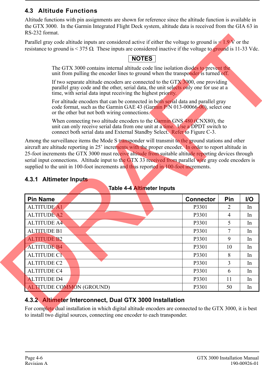
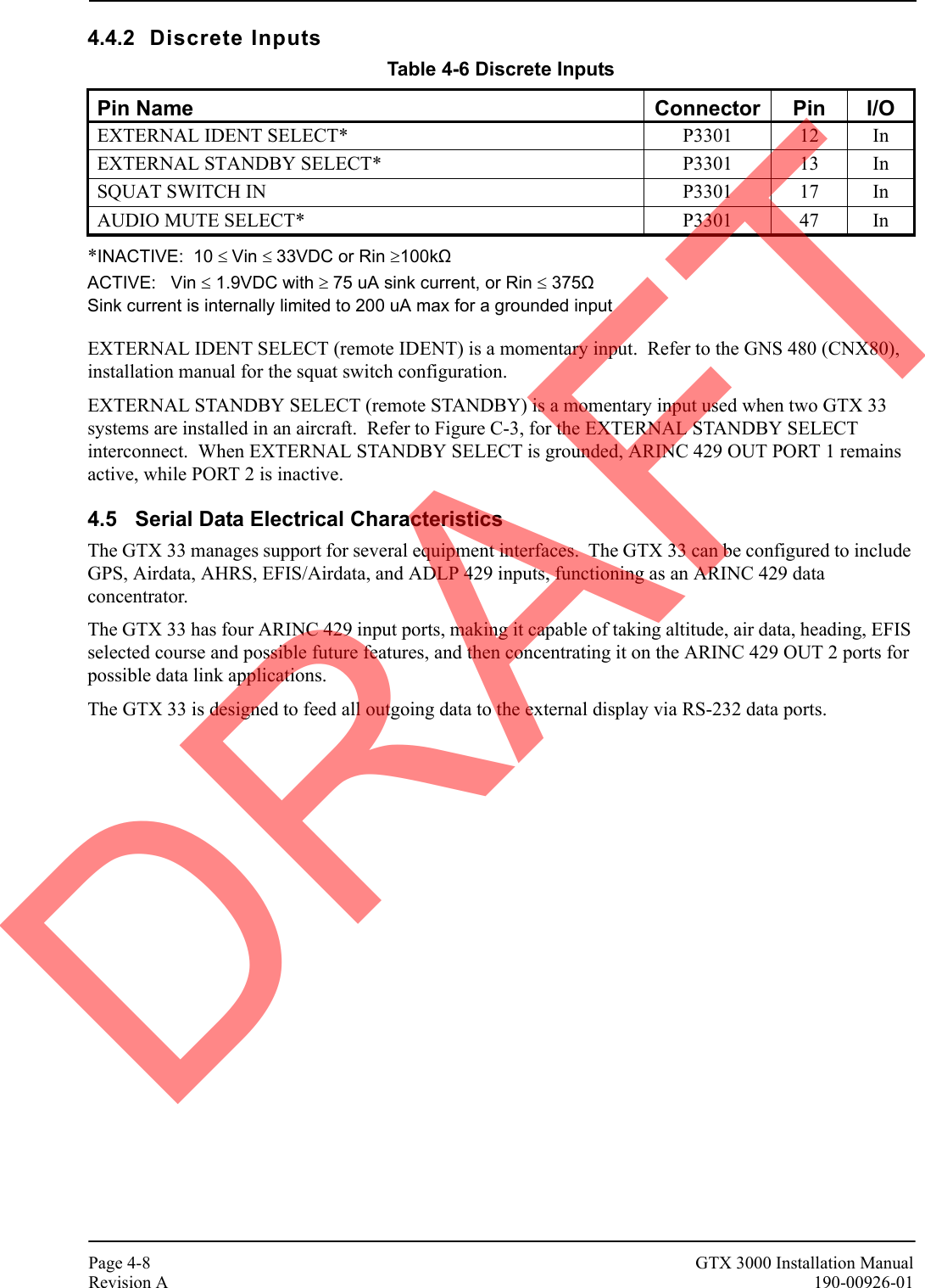
![GTX 3000 Installation Manual Page 4-7190-00926-01 Revision A4.3.3 Altimeter Selection PriorityWhen connecting the transponder to a GNS 480 (CNX80), the installer must be aware of the GTX 33 priority for selecting encoded altimeter interconnections. The GTX 33 searches in this sequence for altitude, and stops when it finds a valid pressure altitude input.Altitude reporting equipment order of precedence:1) ARINC 429 Air Data Computer (label 203, if configured W/ALT) (25’)2) ARINC 429 EFIS (label 203, if configured W/ALT) (25’)3) RS-232 data from GNS 480 (CNX80), or Garmin Integrated Flight Deck (25')4) RS-232 Fuel/Air Data Computer (if configured W/ALT.) (25’)5) Shadin Altitude Serializer/Encoder (if configured for 25’)6) Icarus Altitude Serializer/Encoder (if configured for 25’)7) Parallel wire Gray Code input (100’)8) Shadin Altitude Serializer/Encoder (if configured for 100’)9) Icarus Altitude Serializer/Encoder (if configured for 100’)Only approved devices may provide altitude to the GTX 33 in accordance with 14 CFR 91.217. In addition, all altitude reporting devices installed in the aircraft must meet certification requirements of 14 CFR 91.413. The installer must select an altitude reporting device that is a certified altitude source for the particular aircraft.It is the installing agency’s responsibility to determine that the installed encoder is compatible with the selected altitude reporting criteria, either 100’ or 25’. Refer to the GNS 480 (CNX80), installation manual 560-0982-01 for the altitude data reporting configuration.For additional information, refer to GNS 480 (CNX80) Installation Manual 560-0982-01 for the altitude data reporting configuration when connecting a GTX 330 to a GNS 480 (CNX80).4.4 Discrete FunctionsDiscrete functions with pin assignments are shown for reference since the functions are available in the GTX 3000. External suppression should be connected if another transponder or DME is installed in the aircraft avionics system. Depending on system configuration, the Garmin Integrated Flight Deck may not use these inputs, as many functions are received from the GIA 63 in RS-232 format.4.4.1 Discrete OutputsExternal suppression should be connected if a DME is installed in the aircraft avionics system. The GTX 3000 suppression I/O pulses may not be compatible with all models of DME. Known incompatible units include the Bendix/King KN 62, KN 64 and KNS 80. These models have an output-only suppression port and can be damaged by the GTX 3000 mutual suppression output. In this case, leave the suppression pin open.*INACTIVE: 10 ≤ Vin ≤ 33VDC or Rin ≥100kΩ ACTIVE: Vin ≤ 1.9VDC with ≥ 75 uA sink current, or Rin ≤ 375Ω Sink current is internally limited to 200 uA max for a grounded input Table 4-5 Discrete OutputsPin Name Connector Pin I/OALTITUDE ALERT ANNUNCIATE* P3301 19 OutEXTERNAL SUPPRESSION I/O (TXP/DME) P3301 31 I/ORESERVED [SIGNAL GROUND] P3301 51 --RESERVED [SIGNAL GROUND] P3301 58 --DRAFT](https://usermanual.wiki/Garmin/01443/User-Guide-1694649-Page-35.png)
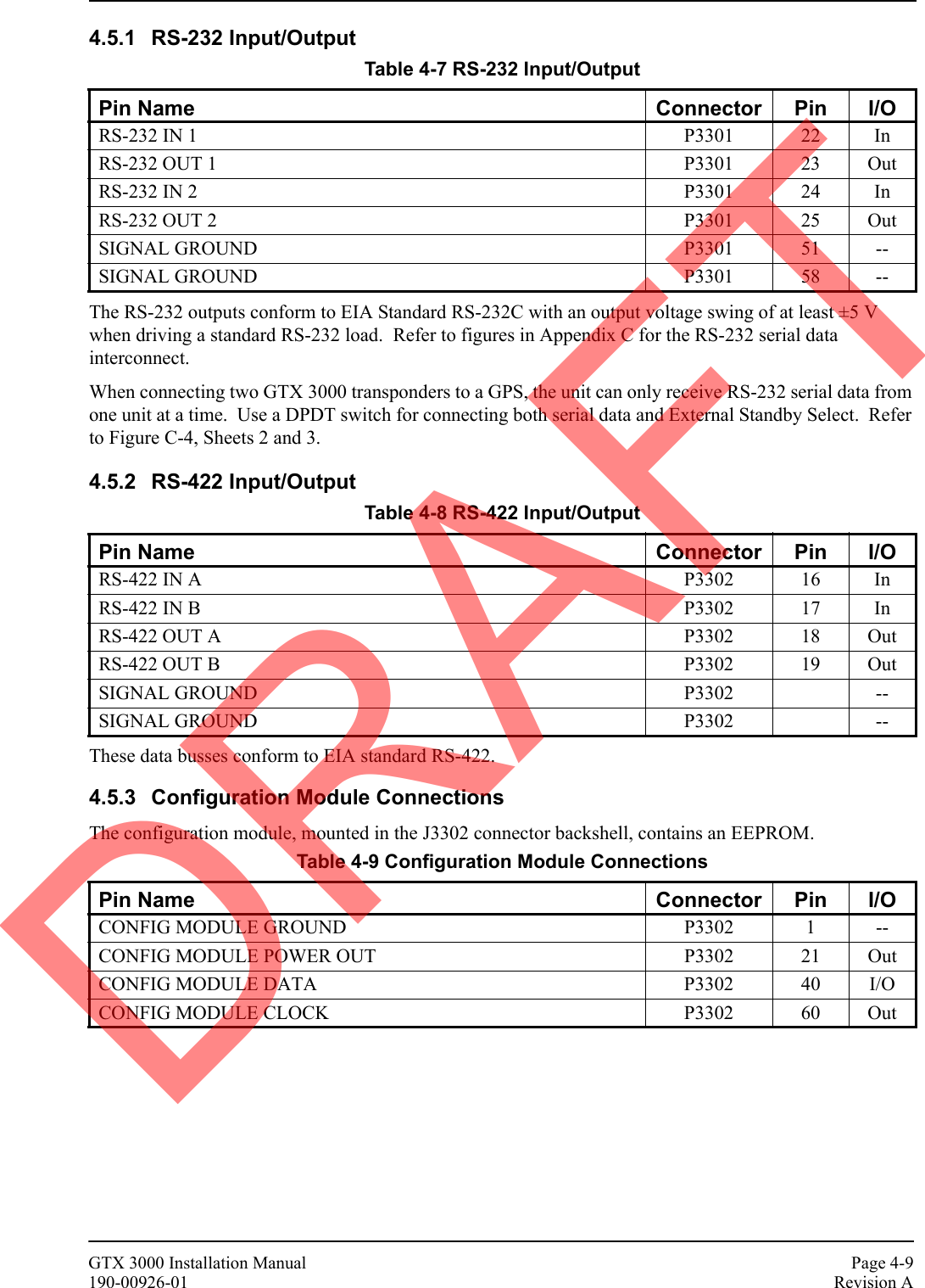
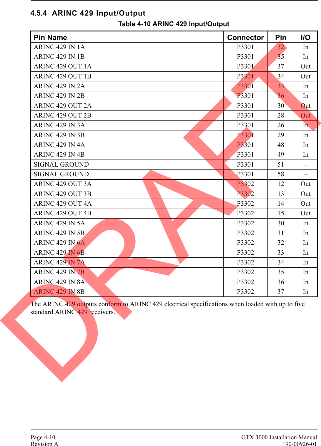
![GTX 3000 Installation Manual Page 4-11190-00926-01 Revision AThe following data is sent out at specified intervals using high speed ARINC 429 (100 kHz). The transmit data labels and their rates are as follows:4.6 RS-232 Input/Output, Software Update ConnectionsWhen the GTX 33 is installed in a system other than a Garmin Integrated Flight Deck an optional RS-232 serial data connector should be installed in the aircraft for future software upgrades, negating the need to remove the transponder from the aircraft. The connector can be mounted anywhere convenient for access, such as under the instrument panel, on a remote avionics shelf next to the unit or in the instrument panel itself. Be sure to label the connector for Software Update. Do not include the Test Mode Select switch in the aircraft. See Figure 4-3 for software update connections.If the GTX 33 installation interfaces with a GNS 480 (CNX80) in the aircraft, the GNS 480 (CNX80) must be turned off during GTX 330 software upload, due to loading of RS-232 port 1.The installation of an optional software upgrade connector is highly recommended. If the connector is wired in the aircraft, transponder removal and reinstallation for software upgrade is not required.If the unit is removed from the aircraft and operated, always connect J3302, (and J3303 for GTX 33D) to an antenna or a 50 Ω, 5-Watt load. The GTX 33 transmits Mode S acquisition squitter replies about once per second whether interrogations are received or not.Beginning with software version 3.06, the GTX 33 software can be updated in the Configuration mode as well as in Test mode. Updating software in Configuration mode does not require the TEST MODE SELECT switch.Table 4-11 Transmit Data LabelsLABEL DATA RATE100 Selected Course (degrees) 200 ms203 Pressure Altitude [in feet set to 29.92” Hg (1013.25 mb)] 100 ms204 Barometric Corrected Altitude (feet) 100 ms206 Indicated Air Speed (knots) 100 ms210 True Air Speed (knots) 100 ms211 Total Air Temperature (degrees) 100 ms213 Static Air Temperature (degrees) 100 ms306 Joystick Lat 500 ms307 Joystick Lon 500 ms314 True Heading 100 ms320 Magnetic Heading (Degrees) 100 ms371 GA Equipment Identifier 500 ms377 Equipment Identifier 500 msNOTECAUTIONDRAFT](https://usermanual.wiki/Garmin/01443/User-Guide-1694649-Page-39.png)

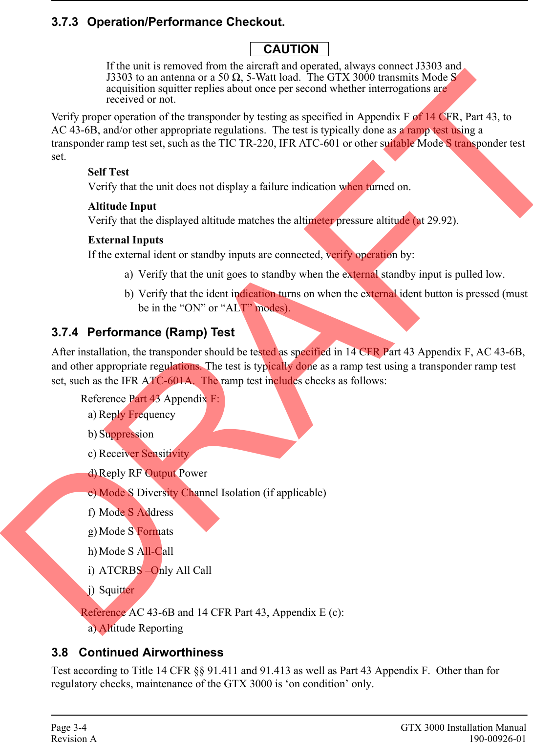
![GTX 3000 Installation Manual Page B-1190-00926-01 Revision AAPPENDIX B Assembly and Installation DrawingsFigure B-1 GTX 3000 Outline Drawing4.1 104CENTER OF GRAVITY3.0 76CENTEROF GRAVITY1.3 33CENTEROF GRAVITYNOTES:DIMENSIONS: INCHES[mm].1.DIMENSIONS ARE SHOWN FOR REFERENCE ONLY.2.MOUNTING HOLES FOR #10 PANHEAD OR HEX HEAD FASTENERS (4 PLACES).3.228.38.9949.71.956.47 164.2(TNC CONNECTOR)P3301P3302BTM(TNC CONNECTOR)TOP2X 1.775 45.09.400 10.162X 7.000 .88 22.4177.802.58 65.42X2X4X .210 5.33SEE NOTE 3DRAFT](https://usermanual.wiki/Garmin/01443/User-Guide-1694649-Page-43.png)