Garmin 01443 LICENSED NON-BROADCAST AERONAUTICAL TRANSMITTER User Manual 190 00926 01 0A
Garmin International Inc LICENSED NON-BROADCAST AERONAUTICAL TRANSMITTER 190 00926 01 0A
Garmin >
Users Manual
190-00926-01 October, 2011 Revision A
GTX 3000
Transponder Installation Manual
DRAFT
Page A GTX 3000 Installation Manual
Revision A 190-00926-01
© Copyright 2011
Garmin Ltd. or its subsidiaries
All Rights Reserved
Except as expressly provided herein, no part of this manual may be reproduced, copied,
transmitted, disseminated, downloaded or stored in any storage medium, for any purpose without
the express prior written consent of Garmin. Garmin hereby grants permission to download a
single copy of this manual and of any revision to this manual onto a hard drive or other electronic
storage medium to be viewed and to print one copy of this manual or of any revision hereto,
provided that such electronic or printed copy of this manual or revision must contain the complete
text of this copyright notice and provided further that any unauthorized commercial distribution of
this manual or any revision hereto is strictly prohibited.
Garmin International, Inc.
1200 E. 151st Street
Olathe, KS 66062 USA
Telephone: 913.397.8200
Aviation Panel-Mount Technical Support Line (Toll Free) 1.888.606.5482
www.garmin.com
Garmin (Europe) Ltd.
Liberty House, Bulls Copse Road
Hounsdown Business Park
Southampton, SO40 9RB U.K.
+44/ (0) 870.8501241
Garmin AT, Inc.
2345 Turner Rd., SE
Salem, OR 97302 USA
Telephone: 503.581.8101
RECORD OF REVISIONS
Revision Revision Date Description
A 10/31/2011 Initial Release
DRAFT
GTX 3000 Installation Manual Page i
190-00926-01 Revision A
INFORMATION SUBJECT TO EXPORT CONTROL LAWS
This document may contain information which is subject to the Export Administration Regulations
("EAR") issued by the United States Department of Commerce (15 CFR, Chapter VII, Subchapter C) and
which may not be exported, released, or disclosed to foreign nationals inside or outside of the United States
without first obtaining an export license. The preceding statement is required to be included on any and all
reproductions in whole or in part of this manual.
This product, its packaging, and its components contain chemicals known to the
State of California to cause cancer, birth defects, or reproductive harm. This
Notice is being provided in accordance with California's Proposition 65. If you
have any questions or would like additional information, please refer to our web
site at www.garmin.com/prop65.
Perchlorate Material – special handling may apply, See www.dtsc.ca.gov./
hazardouswaste/perchlorate.
CURRENT REVISION DESCRIPTION
DOCUMENT PAGINATION
WARNING
WARNING
Revision Page
Number(s)
Section
Number Description of Change
A All All Initial release
Section Page Range
Table of Contents i – vi
Section 1 1-1 – 1-8
Section 2 2-1 – 2-8
Section 3 3-1 – 3-4
Section 4 4-1 – 4-12
Appendix A A-1 – A-2
Appendix B B-1 – B-3
DRAFT

Page ii GTX 3000 Installation Manual
Revision A 190-00926-01
TABLE OF CONTENTS
PARAGRAPH PAGE
Section 1 GENERAL DESCRIPTION............................................................. 1-1
1.1 Introduction ..................................................................................................................... 1-1
1.2 Equipment Description.................................................................................................... 1-1
1.3 Interface Summary ..........................................................................................................1-2
1.4 Technical Specifications ................................................................................................. 1-3
1.4.1 General Specifications ........................................................................................................ 1-3
1.4.2 Transponder Capabilities .................................................................................................... 1-4
1.4.3 ADS-B Capabilities ............................................................................................................ 1-5
1.4.4 Physical Characteristics ...................................................................................................... 1-6
1.4.5 Power Requirements ........................................................................................................... 1-6
1.5 License Requirements ..................................................................................................... 1-6
1.6 Certification..................................................................................................................... 1-6
1.6.1 TSO/ETSO/RTCA/ICAO Compliance............................................................................... 1-7
1.6.2 TSO/ETSO Deviations........................................................................................................ 1-7
1.7 Reference Documents ..................................................................................................... 1-7
1.8 Aviation Limited Warranty ............................................................................................. 1-8
Section 2 INSTALLATION OVERVIEW....................................................... 2-1
2.1 Introduction ..................................................................................................................... 2-1
2.2 Installation Materials....................................................................................................... 2-1
2.2.1 Equipment Available .......................................................................................................... 2-1
2.2.2 Additional Equipment Required ......................................................................................... 2-2
2.3 Installation Considerations.............................................................................................. 2-2
2.3.1 Preservation of Previous Systems....................................................................................... 2-2
2.3.2 Antenna Location Considerations....................................................................................... 2-3
2.4 Cabling and Wiring .........................................................................................................2-4
2.4.1 Cable Routing Considerations ............................................................................................ 2-5
2.5 Installation Approval Considerations for Pressurized Aircraft....................................... 2-6
2.6 Cooling Air...................................................................................................................... 2-6
2.7 GTX 3000 Mounting Requirements................................................................................ 2-6
2.7.1 Remote Mounted Stand-Alone Rack Considerations ......................................................... 2-7
Section 3 INSTALLATION PROCEDURE .................................................... 3-1
3.1 Unpacking Unit ............................................................................................................... 3-1
3.2 Wiring Harness Installation............................................................................................. 3-1
3.3 Backshell Assembly ........................................................................................................3-2
3.4 Weight and Balance ........................................................................................................ 3-2
3.5 Electrical Load Analysis .................................................................................................3-3
3.5.1 Circuit Breaker Placard....................................................................................................... 3-3
3.6 Final Installation.............................................................................................................. 3-3
3.7 Post Installation Configuration and Checkout ................................................................ 3-3
3.7.1 Configuration ...................................................................................................................... 3-3
3.7.2 Interference Check.............................................................................................................. 3-3
DRAFT

GTX 3000 Installation Manual Page iii
190-00926-01 Revision A
TABLE OF CONTENTS
PARAGRAPH PAGE
3.7.3 Operation/Performance Checkout....................................................................................... 3-4
3.7.4 Performance (Ramp) Test................................................................................................... 3-4
3.8 Continued Airworthiness ................................................................................................ 3-4
Section 4 SYSTEM INTERCONNECTS......................................................... 4-1
4.1 Pin Function List ............................................................................................................. 4-1
4.1.1 P3301 .................................................................................................................................. 4-1
4.1.2 P3302 .................................................................................................................................. 4-3
4.2 Power Function ............................................................................................................... 4-5
4.2.1 Aircraft Power..................................................................................................................... 4-5
4.3 Altitude Functions........................................................................................................... 4-6
4.3.1 Altimeter Inputs .................................................................................................................. 4-6
4.3.2 Altimeter Interconnect, Dual GTX 3000 Installation ......................................................... 4-6
4.3.3 Altimeter Selection Priority ................................................................................................ 4-7
4.4 Discrete Functions........................................................................................................... 4-7
4.4.1 Discrete Outputs.................................................................................................................. 4-7
4.4.2 Discrete Inputs .................................................................................................................... 4-8
4.5 Serial Data Electrical Characteristics.............................................................................. 4-8
4.5.1 RS-232 Input/Output........................................................................................................... 4-9
4.5.2 RS-422 Input/Output........................................................................................................... 4-9
4.5.3 Configuration Module Connections.................................................................................... 4-9
4.5.4 ARINC 429 Input/Output ................................................................................................. 4-10
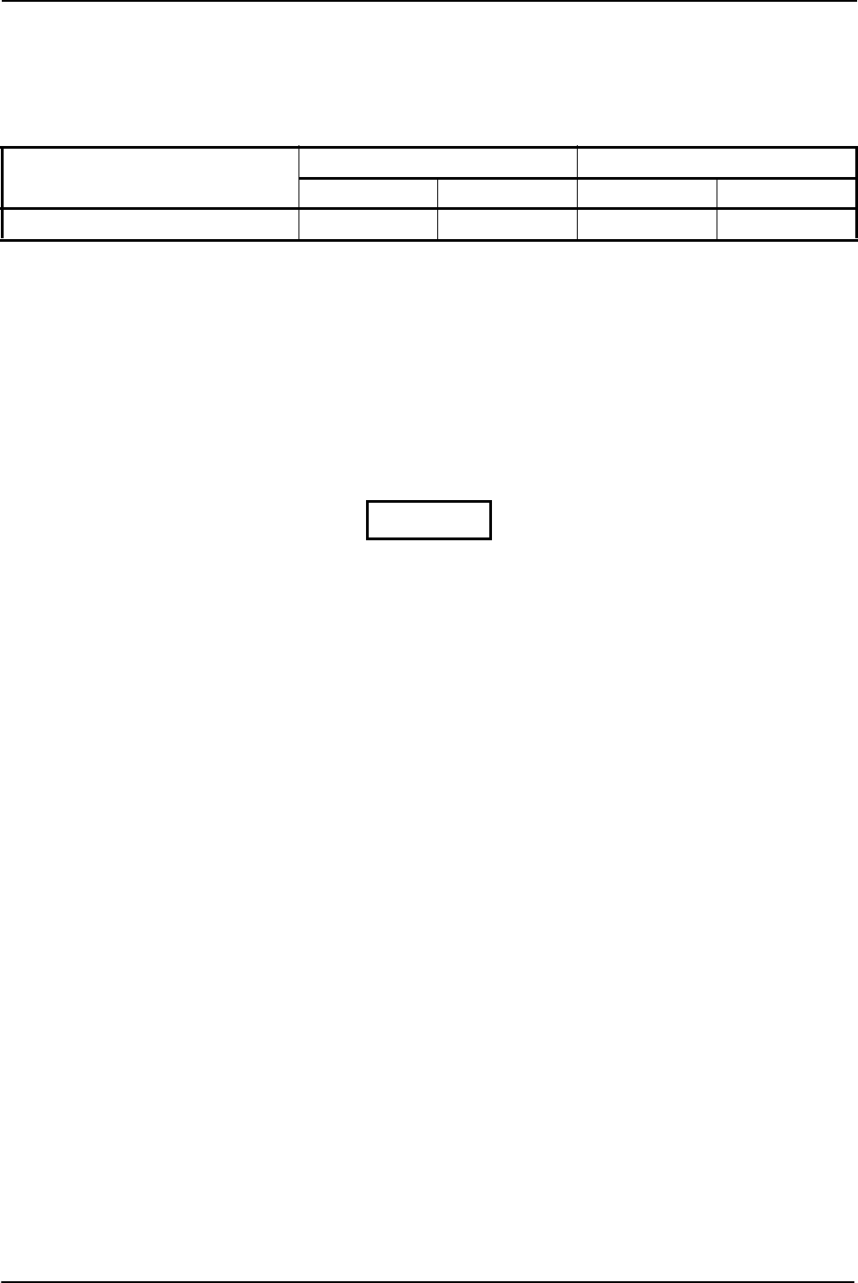
4.6 RS-232 Input/Output, Software Update Connections................................................... 4-11
Appendix A Construction and Validation of Structures............................... A-1
A.1 Static Test Loading....................................................................................................... A-1
A.2 Determining Static Load Capability............................................................................. A-1
Appendix B Assembly and Installation Drawings ..........................................B-1
DRAFT

Page iv GTX 3000 Installation Manual
Revision A 190-00926-01
LIST OF FIGURES
FIGURE PAGE
Section 1 GENERAL DESCRIPTION............................................................. 1-1
Section 2 INSTALLATION OVERVIEW....................................................... 2-1
Figure 2-1 Antenna Installation Considerations ...................................................................2-3
Figure 2-2 GTX 3000 Stand Rack (011-02515-00) .............................................................. 2-7
Figure 2-3 GTX 3000 Rack, Suggested Mounting Locations............................................... 2-8
Section 3 INSTALLATION PROCEDURE .................................................... 3-1
Section 4 SYSTEM INTERCONNECTS......................................................... 4-1
Figure 4-1 View of J3301 connector, looking at unit ........................................................... 4-1
Figure 4-2 View of J3302 connector, looking at unit ........................................................... 4-3
Figure 4-3 GTX 3000 Software Update Connections......................................................... 4-12
Appendix A Construction and Validation of Structures............................... A-1
Figure A-1 Upward static Load Test.................................................................................... A-2
Figure A-2 Forward Static Load Test .................................................................................. A-2
Appendix B Assembly and Installation Drawings..........................................B-1
Figure B-1 GTX 3000 Outline Drawing .............................................................................. B-1
Figure B-2 GTX 3000 Connector/Rack Assembly Drawing ............................................... B-2
Figure B-3 GTX 3000 Minimum Installation/Removal Clearance...................................... B-3
DRAFT

GTX 3000 Installation Manual Page v
190-00926-01 Revision A
LIST OF TABLES
TABLE PAGE
Section 1 GENERAL DESCRIPTION............................................................. 1-1
Table 1-1 General Specifications .......................................................................................... 1-3
Table 1-2 Transponder Capabilities ...................................................................................... 1-4
Table 1-3 GTX 3000 with 011-02515-00 Rack .................................................................... 1-6
Table 1-4 Power Requirements ............................................................................................. 1-6
Table 1-5 TSO/ETSO/RTCA/ICAO Compliance................................................................. 1-7
Table 1-6 TSO/ETSO Deviations ......................................................................................... 1-7
Table 1-7 Reference Documents ........................................................................................... 1-7
Section 2 INSTALLATION OVERVIEW....................................................... 2-1
Table 2-1 Installation Materials ............................................................................................ 2-1
Table 2-2 Available Equipment ............................................................................................ 2-1
Table 2-3 Connector Kit (011-02019-00) ............................................................................. 2-1
Table 2-4 Connector Kit, 90 Degree (011-02019-01)........................................................... 2-2
Table 2-5 Cable Specifications ............................................................................................. 2-4
Table 2-6 Maximum Difference in Cable Lengths ............................................................... 2-5
Section 3 INSTALLATION PROCEDURE .................................................... 3-1
Table 3-1: Pin Contact Part Numbers ................................................................................... 3-1
Table 3-2 Recommended Crimp Tools ................................................................................. 3-2
Table 3-3 Unit Power Loads ................................................................................................. 3-3
Section 4 SYSTEM INTERCONNECTS......................................................... 4-1
Table 4-1 P3301 Pin List.......................................................................................................4-1
Table 4-2 P3302 Pin List.......................................................................................................4-3
Table 4-3 Aircraft Power ...................................................................................................... 4-5
Table 4-4 Altimeter Inputs ....................................................................................................4-6
Table 4-5 Discrete Outputs ................................................................................................... 4-7
Table 4-6 Discrete Inputs ......................................................................................................4-8
Table 4-7 RS-232 Input/Output ............................................................................................ 4-9
Table 4-8 RS-422 Input/Output ............................................................................................ 4-9
Table 4-9 Configuration Module Connections .....................................................................4-9
Table 4-10 ARINC 429 Input/Output ................................................................................. 4-10
Table 4-11 Transmit Data Labels........................................................................................ 4-11
Appendix A Construction and Validation of Structures .............................. A-1
Table A-1 Static Test Load .................................................................................................. A-1
Appendix B Assembly and Installation Drawings..........................................B-1
DRAFT

Page vi GTX 3000 Installation Manual
Revision A 190-00926-01
DRAFT

GTX 3000 Installation Manual Page 1-1
190-00926-01 Revision A
1 GENERAL DESCRIPTION
1.1 Introduction
This manual provides mechanical and electrical information for installing a GTX3000 as part of a Garmin
Integrated Flight Deck.
1.2 Equipment Description
The Garmin GTX 3000 is a remote-mount Mode S and ADS-B compliant transponder suitable for
installation in part 25 jets and any class of part 23 aircraft. It implements ARINC, UF16 and DF16, and
BDS(3,0) support for TCAS II operation. The unit has high transmit power sufficient to accommodate
longer (lossier) antenna cable runs in larger aircraft while still meeting TSO requirements for transmit
power. It is also designed and certified to meet DO-160 categories suitable for installation outside the
pressure vessel and in aircraft where safety expectations high. The GTX 3000 is designed to be controlled
from other Garmin avionics such as a GDU or GTC. These avionics will also typically provide (over the
same connection) fundamental data the transponder needs such as pressure altitude.
The Garmin GTX 3000 is a Mode A, C, and S transponder. It is certified under TSO-C112c and ETSO-
C112c. The Mode S minimum operating performance specifications for these TSOs (“MOPS,” which are
RTCA DO-181D and EUROCAE ED-73C respectively) define a labeling convention that identifies the
primary characteristics of a transponder. The GTX 3000’s label is “level 2adens, Class 2”.
This label identifies that the GTX3000 supports:
• Basic data link support (level 2)
• TCAS compatibility (the “a” in “adens”)
• Antenna diversity operation (the “d” in “adens”)
• Extended squitter (the “e” in “adens”)
• Enhanced surveillance (including elementary surveillance) (the “n” in “adens”)
• Surveillance identifier codes (the “s” in “adens”)
• Higher minimum transmit power and reply rate (Class 1)
Basic data link support: The “level” (e.g. level 2) of the transponder is an indication of what degree of data
link support the transponder has. Level 1 indicates no support. Level 5 indicates support for sending and
receiving extended length messages to multiple interrogators at the same time. The GTX3000 is a level 2
transponder in order to support elementary and enhanced surveillance as well as TCAS-II communication.
It is not a level 3, 4, or 5 transponder because there are not common applications that use the extended
length messaging these levels support.
TCAS compatibility: The GTX 3000’s TCAS compatibility consists of an ARINC 429 interface based on
the ARINC 735B specification. It is designed to be connected to a Garmin TCAS, and its primary purpose
is to provide resolution advisory coordination with other TCAS-II aircraft.
Antenna diversity: The GTX 3000 implements antenna diversity because it improves air-to-air surveillance
and communication, and it is required for TCAS-II operation. The Mode S MOPS also recommends
diversity for aircraft “with gross mass in ecess of 5,700 kg or a maximum cruising true airspeed capability
in excess of 324 km/h (175 kt).”
Extended squitter relates to ADS-B, which is discussed in the following paragraphs.
Elementary and enhanced surveillance use the Mode S data link to provide ATC information regarding
aircraft identification, TCAS information, vertical intention, track and turn, and heading and speed. This
information may be displayed on an air traffic controller’s radar display or it may be used in ground system
processing for functions such as detection of level bust or early recognition of aircraft maneuvers.
Ultimately this information is made available to improve safety and capacity. Flight in Europe has
mandates for elementary surveillance on most aircraft and enhanced surveillance on some aircraft.
DRAFT

Page 1-2 GTX 3000 Installation Manual
Revision A 190-00926-01
Surveillance identifier (SI) codes are a set of 64 IDs that uniquely identify ground radars within a Mode S
coverage area. SI codes were a later expansion upon the original 16 ID “interrogator codes” that allows a
reduction in ground station infrastructure complexity. These 16+64 ID codes allow transponders to
communicate with select ground stations when the transponder is within range of multiple ground stations.
Flight in Europe mandates a transponder support SI codes.
Class 1: The Mode S MOPS defines two classes of Mode S transponders: class1 and class 2. Class 1
equipment has higher minimum transmit power and reply rates than class 2 equipment. The MOPS
explains that class 2 equipment is intended to be restricted to aircraft that operate below 15,000 feet
altitude and have a maximum cruising true airspeed below 175 kt. Class 1 transponders are for aircraft that
operate above those speed and altitude boundaries.
ADS-B transmit is the GTX3000’s other primary function. The unit is certified to TSO-C166b and ETSO-
C166a. It is certified to meet the DO-260B MOPS. The unit is a class B1 device per RTCA DO-260B.
This indicates the GTX3000 is transmit-only device for aircraft (vs ground vehicles or fixed objects) with a
minimum of 125 watts peak pulse power and supporting the following messages:
• Airborne Position
• Surface Position
• A/C Identification & Category
• Airborne Velocity
• A/C Operational Status
• Extended Squitter A/C Status.
1.3 Interface Summary
The GTX 3000 provides the following interface connections via the rear connector. See Section 4 and
Appendix C for connection details.
• Diversity Antenna Ports
• Two bidirectional RS-232 and one bidirectional RS-422 serial connections for data and control
• Eight ARINC 429 inputs and four ARINC 429 outputs supporting various ARINC protocols to
maximize options for connectivity and allow redundancy
• Ten (10) encoding altimeter inputs
• External IDENT input
• External suppression pulse input/output
• Switched power output of up to 1.5 amps (for powering an encoding altimeter)
• Remote power turn on
DRAFT

GTX 3000 Installation Manual Page 1-3
190-00926-01 Revision A
1.4 Technical Specifications
1.4.1 General Specifications
Note:
1. Each unit’s external suppression is tested to the specifications above. The design based on the
specifications in ARINC 718A Attachment 6 and ARINC 735A Attachment 8.
Table 1-1 General Specifications
Characteristic Specification
Environmental Qualification
Form 0050-00503-01
FCC Authorization Emission Designator 12M0M1D
Antenna Compatibility
Compatible with any antenna certified to one of the following TSOs:
TSO-C66() [DME TSO]
TSO-C74() [ATCRBS TSO]
TSO-C112() [Mode S TSO]
Antenna Cable Requirements Cable + bulkhead connector loss @1090 MHz < 3.0 dB
Transmitter Power 250 Watts minimum, 500 Watts nominal
Transmitter Frequency 1090 MHz ±1 MHz
Receiver Frequency 1030 MHz
Receiver Sensitivity -74 dBm nominal for 90% replies
External Suppression Input Low ≤ 1.0 V; High ≥ 9 V
External Suppression Output Minimum is greater than +8V into 350 Ω in parallel w/ 1800 pF
Maximum is less than +36V into any load
DRAFT

Page 1-4 GTX 3000 Installation Manual
Revision A 190-00926-01
1.4.2 Transponder Capabilities
Note 1: The GTX 3000 does not source the data for extended squitter / ADS-B messages. The GTX 3000
must receive this data from other equipment in order to provide extended squitter / ADS-B functionality.
Also, ADS-B must be configured on.
Note 2: Compliance with elementary and enhanced surveillance is shown at the installation-level per AMC
20-18 and AMC20-13. The GTX 3000 implements the technical requirements necessary of a transponder
that AMC 20-18 and AMC 20-13 require, but installation of a GTX 3000 does not constitute compliance
with elementary and enhanced surveillance. Also, in order for the GTX 3000 to meet the technical
requirements of AMC 20-13 for enhanced surveillance, the GTX 3000 must have enhanced surveillance
configured on and it must receive data to populate the relevant BDS registers.
BDS Register Support
The following Binary Data Selector (BDS) registers are supported.
General Mode S Registers:
• BDS (0,0) Air Initiated Comm-B (AICB)
• BDS (1,0) Data Link Capability Report
• BDS (1,7) Common Usage Ground Initiated Comm-B (GICB) Capability Report
• BDS (1,8) Mode S Specific Services GICB Capability Report
• BDS (1,9) Mode S Specific Services GICB Capability Report
• BDS (1,C) Mode S Specific Services Protocols (MSP) Capability Report
Elementary Surveillance Registers
• BDS (2,0) Aircraft Identification
• BDS (2,1) Aircraft and Airline Registration Markings
• BDS (2,5) Aircraft Type
• BDS (3,0) TCAS/ACAS Active Resolution Advisory
Table 1-2 Transponder Capabilities
Characteristic Specification
Mode A Capability 4096 Identification Codes
Mode C Capability
100 Foot Increments from -1000 to 62,700 feet.
25 Foot Increments from -1000 to 50,
175 feet with suitable serial data altitude.
Mode S Uplink Capability UF0, UF4, UF5, UF11, UF16, UF20, UF21
Mode S Downlink Capability DF0, DF4, DF5, DF11, DF16, DF17, DF20, DF21
Data link capability Level 2, Comm-A, Comm-B, Comm-U, Comm-V
TCAS II support Yes
Diversity Yes
Extended squitter Yes, see note 1
Elementary surveillance Yes, see note 2
Enhanced surveillance Yes, see note 2
SI code support Yes
(E)TSO-C112c class Class 1
DRAFT

GTX 3000 Installation Manual Page 1-5
190-00926-01 Revision A
Enhanced Surveillance Registers
• BDS (4,0) Selected Vertical Intention
• BDS (5,0) Track and Turn Report
• BDS (6,0) Heading and Speed Report
Extended Squitter/ADS-B Registers
• BDS (0,5) Airborne Position Message
• BDS (0,6) Surface Position Message
• BDS (0,7) Extended Squitter Status
• BDS (0,8) Aircraft Identification and Category Message
• BDS (0,9) Airborne Velocity Message – Subtypes 1, 2, 3, and 4
• BDS (0,A) Event Driven Data
• BDS (6,1) Aircraft Status Message – Subtypes 1 and 2
• BDS (6,5) Aircraft Operational Status – Subtypes 1 and 2
The GTX3000 sources data for:
• Air-initiated Comm B (BDS(0,0))
• Most bits in the capability reports (BDS(1,x))
• Aircraft identification registers (BDS(2,x))
The GTX3000 does not source data for registers relating to:
• TCAS functionality (BDS(3,0) and capability bits in BDS(1,0))
• Enhanced surveillance (BDS(4,0), BDS(5,0), and BDS(6,0))
• Extended squitter / ADS-B (BDS(0,5) through BDS(0,A) and BDS(6,1) and BDS(6,5))
Data for these registers must be obtained through a RS-232, RS-422, or ARINC interface.
1.4.3 ADS-B Capabilities
The GTX 3000 is certified to meet the version 2 ADS-B requirements of TSO-C166b / ETSO-C166a and
the RTCA DO-260B MOPS. The MOPS classifies it as a class B1 device. The GTX 3000 is capable of
broadcasting the following ADS-B messages:
• BDS (0,5) Airborne Position Message
• BDS (0,6) Surface Position Message
• BDS (0,7) Extended Squitter Status
• BDS (0,8) Aircraft Identification and Category Message
• BDS (0,9) Airborne Velocity Message – Subtypes 1, 2, 3, and 4
• BDS (0,A) Event Driven Data
• BDS (6,1) Aircraft Status Message – Subtypes 1 and 2
• BDS (6,5) Aircraft Operational Status – Subtypes 1 and 2
The GTX 3000 does not source the data for ADS-B messages. It must receive this data from its RS-232,
RS-422, or ARINC inputs. Units in a Garmin Integrated Flight Deck such as the G5000 will typically
provide this data to the GTX 3000.
In order to transmit these messages, the GTX 3000 must have ADS-B enabled in its configuration.
DRAFT
Page 1-6 GTX 3000 Installation Manual
Revision A 190-00926-01
1.4.4 Physical Characteristics
1.4.5 Power Requirements
1.5 License Requirements
The Telecommunications Act of 1996, effective February 8, 1996, provides the FCC discretion to
eliminate radio station license requirements for aircraft and ships. The GTX 3000 installation must
comply with current transmitter licensing requirements. To find out the specific details on whether a
particular installation is exempt from licensing, please visit the FCC web site
http://wireless.fcc.gov/aviation.
If an aircraft license is required, make application for a license on FCC form 404, Application for Aircraft
Radio Station License. The FCC also has a fax-on-demand service to provide forms by fax. The
GTX 3000 owner accepts all responsibility for obtaining the proper licensing before using the GTX 3000.
The UHF transmitter in this equipment is guaranteed to meet federal
communications commission acceptance over the operating temperature range.
Modifications not expressly approved by Garmin could invalidate the license and
make it unlawful to operate the equipment.
1.6 Certification
The conditions and tests required for TSO approval of this article are minimum performance standards. It
is the responsibility of those installing this article either on or within a specific type or class of aircraft to
determine that the aircraft installation conditions are within the TSO standards. TSO articles must have
separate approval for installation in an aircraft. The article may be installed only if performed under
14 CFR Part 43 or the applicable airworthiness requirements.
Table 1-3 GTX 3000 with 011-02515-00 Rack
Characteristic Specification
Width, Unit in Rack 2.58 inches (65.4 mm)
Height, Unit in Rack 6.47 inches (164.2 mm)
Depth (rack w/connectors) 10.94 inches (278 mm)
Weight, Unit only 5.2 lbs (2.36 kg)
Connecter (including backshell) and Rack Weight 0.7 lbs (0.32 kg)
Installed Weight (unit, rack, and connectors) 5.9 lbs (2.68 kg)
Table 1-4 Power Requirements
Characteristic Specification
Input Voltage 14/28 Vdc See the Environmental Qualification Form for details
on surge ratings and minimum/maximum operating voltages.
Power Input 22 Watts Typical, 45 Watts Maximum
Maximum Full TSO Reply Rate;
1200 PRF, Code 7777 1.6 A @ 28 Vdc, 3.6 A @14 Vdc
Maximum Quiescent 0.85 A @ 28 Vdc, 1.7A @ 14 Vdc
CAUTION
DRAFT

GTX 3000 Installation Manual Page 1-7
190-00926-01 Revision A
1.6.1 TSO/ETSO/RTCA/ICAO Compliance
1.6.2 TSO/ETSO Deviations
1.7 Reference Documents
The following publications are sources of additional information for installing the GTX 3000. Before
installing the unit, the technician should read all relevant referenced materials along with this manual.
Table 1-5 TSO/ETSO/RTCA/ICAO Compliance
Function
Performance
Standard
(TSO/ETSO/RTCA/
EUROCAE)
Category
Applicable
LRU SW
Part
Numbers
CLD Part
Numbers
Air Traffic Control Radar
Beacon System/Mode Select
(ATCRBS/MODE S) Airborne
Equipment
TSO-C112c
Level
2adens
Class 2
All
006-B0912-00
All
006-C0129-00
ETSO-2C112c
Extended Squitter Automatic
Dependent Surveillance –
Broadcast (ADS-B) and Traffic
Information Services –
Broadcast (TIS-B) on the
Radio Frequency of 1090 MHz
TSO-C166b
B1
(diversity)
ETSO-C166a
RTCA DO-178B Compliance DO-178B Level B
RTCA DO-254 Compliance DO-254 Level B
Table 1-6 TSO/ETSO Deviations
TSO/ETSO Deviation
TSO-C112c Garmin was granted a deviation from RTCA DO-181D §2.2.22.h to not interface with FAA
TSO-C119a TCAS units.
TSO-C112c Garmin was granted a deviation from RTCA DO-181D §2.2.23.1.3a to use the newer specifi-
cations in RTCA DO-260B §2.2.3.3.2.12.
ETSO-C112c Garmin was granted a deviation from ED-73C section 3.28.3.4 to use the newer specification
in RTCA DO-260B section 2.2.3.3.2.12 instead.
ETSO-C166a Garmin was granted a deviation from to use RTCA DO-260B as the minimum operating per-
formance standard instead of the older RTCA DO-260A.
ETSO-C166a Garmin was granted a deviation from ETSO-C166a section 4.2 to not mark the unit with the
class information.
Table 1-7 Reference Documents
Part Number Document
190-00303-00 G1000 System Installation Manual
190-00303-04 G1000 Line Maintenance and Configuration Manual
DRAFT

Page 1-8 GTX 3000 Installation Manual
Revision A 190-00926-01
1.8 Aviation Limited Warranty
All Garmin avionics products are warranted to be free from defects in materials or workmanship for: one
years from the date of purchase for new Remote-Mount and Panel-Mount products; one year from the date
of purchase for new portable products and any purchased newly-overhauled products; six months for
newly-overhauled products exchanged through a Garmin Authorized Service Center; and 90 days for
factory repaired or newly-overhauled products exchanged at Garmin in lieu of repair. Within the applicable
period, Garmin will, at its sole option, repair or replace any components that fail in normal use. Such
repairs or replacement will be made at no charge to the customer for parts or labor, provided that the
customer shall be responsible for any transportation cost. This warranty does not apply to: (i) cosmetic
damage, such as scratches, nicks and dents; (ii) consumable parts, such as batteries, unless product damage
has occurred due to a defect in materials or workmanship; (iii) damage caused by accident, abuse, misuse,
water, flood, fire, or other acts of nature or external causes; (iv) damage caused by service performed by
anyone who is not an authorized service provider of Garmin; or (v) damage to a product that has been
modified or altered without the written permission of Garmin. In addition, Garmin reserves the right to
refuse warranty claims against products or services that are obtained and/or used in contravention of the
laws of any country.
THE WARRANTIES AND REMEDIES CONTAINED HEREIN ARE EXCLUSIVE AND IN LIEU OF
ALL OTHER WARRANTIES, WHETHER EXPRESS, IMPLIED OR STATUTORY, INCLUDING ANY
LIABILITY ARISING UNDER ANY WARRANTY OF MERCHANTABILITY OR FITNESS FOR A
PARTICULAR PURPOSE, STATUTORY OR OTHERWISE. THIS WARRANTY GIVES YOU
SPECIFIC LEGAL RIGHTS, WHICH MAY VARY FROM STATE TO STATE.
IN NO EVENT SHALL GARMIN BE LIABLE FOR ANY INCIDENTAL, SPECIAL, INDIRECT OR
CONSEQUENTIAL DAMAGES, WHETHER RESULTING FROM THE USE, MISUSE OR
INABILITY TO USE THE PRODUCT OR FROM DEFECTS IN THE PRODUCT. SOME STATES DO
NOT ALLOW THE EXCLUSION OF INCIDENTAL OR CONSEQUENTIAL DAMAGES, SO THE
ABOVE LIMITATIONS MAY NOT APPLY TO YOU.
Garmin retains the exclusive right to repair or replace (with a new or newly-overhauled replacement
product) the product or software or offer a full refund of the purchase price at its sole discretion. SUCH
REMEDY SHALL BE YOUR SOLE AND EXCLUSIVE REMEDY FOR ANY BREACH OF
WARRANTY.
Online Auction Purchases: Products purchased through online auctions are not eligible for warranty
coverage. Online auction confirmations are not accepted for warranty verification. To obtain warranty
service, an original or copy of the sales receipt from the original retailer is required. Garmin will not
replace missing components from any package purchased through an online auction.
International Purchases: A separate warranty may be provided by international distributors for devices
purchased outside the United States depending on the country. If applicable, this warranty is provided by
the local in-country distributor and this distributor provides local service for your device. Distributor
warranties are only valid in the area of intended distribution. Devices purchased in the United States or
Canada must be returned to the Garmin service center in the United Kingdom, the United States, Canada,
or Taiwan for service.
Garmin International, Inc. Garmin (Europe) Ltd.
1200 East 151st Street Liberty House, Bulls Copse Road
Olathe, Kansas 66062, U.S.A. Hounsdown Business Park
Phone:913/397.8200 Romsey, SO40 9RB, U.K.
FAX:913/397.0836 Phone:44/ (0) 870.8501241
FAX:44/ (0) 870.850125
DRAFT

GTX 3000 Installation Manual Page 2-1
190-00926-01 Revision A
2 INSTALLATION OVERVIEW
2.1 Introduction
This section provides hardware equipment information for installing the GTX 3000 Mode S transponder,
related hardware, and optional accessories. Installation of the GTX 3000 should follow the data detailed in
this manual. Cabling is fabricated by the installing agency to fit each particular aircraft. The guidance of
FAA advisory circulars AC 43.13-1B and AC 43.13-2B, where applicable, may be found useful for making
retro-fit installations that comply with FAA regulations.
Refer to the G1000 System Installation Manual, Garmin part number 190-00303-00 for further details on
the mechanical aspects of the G1000 system rack. For installation in an aircraft using the remote mounted
stand-alone rack refer to Appendix B for rack drawings and dimensions.
2.2 Installation Materials
The GTX 3000 is available as a single unit under the following part numbers:
2.2.1 Equipment Available
Each of the following accessories is provided separately for the GTX 3000 unit. Either rack and the
remainder of the accessories are required for installation.
*Note: A transponder antenna approved to TSO C66( ) or C74( ) that has been installed to meet the
requirements of this manual may be used with the GTX 3000.
Table 2-1 Installation Materials
Item Catalog Part Number
GTX 3000 Unit Only (011-01997-00) 010-00736-00
GTX 3000 Standard (011-01997-00), includes connector kit 010-00736-01
Table 2-2 Available Equipment
Item Garmin Number
Configuration Module, w/EEPROM, Jackscrew 011-00979-20
GTX 3000 Rack 011-02515-00
Connector Kit, GTX 3000 011-02019-00
Connector Kit 90 Degree, GTX 3000 011-02019-01
Garmin Transponder Antenna kit* ????????
(two required for diversity) 010-10160-00
Table 2-3 Connector Kit (011-02019-00)
Item Garmin Part Number Quantity
Backshell w/hardware, Jackscrew, 37/62 pin 011-01855-03 1
Backshell w/hardware, Jackscrew, 50/78 pin 011-01855-04 1
Teflon heat shrink tubing, .093 ID 312-00005-05 6 (cm)
High density D-Sub connector, male 62 pin 330-00776-62 1
High density D-Sub connector, male 78 pin 330-00776-78 1
Crimp Contact Pin 22D 336-00021-00 20
Crimp Contact Pin 22D, 18 & 20 AWG 336-00044-00 7
DRAFT

Page 2-2 GTX 3000 Installation Manual
Revision A 190-00926-01
2.2.2 Additional Equipment Required
The following installation accessories are required but not provided:
• Cables – The installer will supply all system cables including circuit breakers. Cable requirements
and fabrication is detailed in Section 3 of this manual.
• Hardware – #6-32 x 100° Flathead SS Screw [(MS24693, AN507R or other approved fastener)
(4 ea.)] for horizontal mounting of the remote stand-alone rack.
• Hardware – #8-32 Panhead Machine Screw [(MS35206, AN526 or other approved fastener) (4 ea.)]
for vertical mounting of the remote stand-alone rack.
• Encoding altitude Digitizer – For GNS 480 (CNX80) and GMX 200 (MX20) installation. Use
encoding altimeter manufacturer’s instructions. The Garmin GAE 43 (Garmin P/N 013-00066-00)
can provide altitude data in either serial or parallel gray code format.
2.3 Installation Considerations
In a Garmin Integrated Flight Deck, the GTX 3000 interfaces with both GIA units. Optional available
discrete line interfaces are shown in Section 4.5 Discrete Functions.
In other system installations, the GTX 3000 can interface with equipment including altimeters and Air
Data Computers (ADC). RS-232, RS-422, and ARINC 429 provide a serial communication path between
interfacing equipment. Fabrication of a wiring harness is required..
2.3.1 Preservation of Previous Systems
It is the installer’s responsibility to preserve the essential characteristic of the aircraft being modified with
this equipment to be in accordance with the aircraft manufacturer’s original design. This includes the
preservation of multiple power buses, which reduces the probability of interrupting power to essential
instruments and avionics.
Table 2-4 Connector Kit, 90 Degree (011-02019-01)
Item Garmin Part Number Quantity
Backshell w/hardware, 90 Degree Jackscrew, 37/62 pin 011-01959-03 1
Backshell w/hardware, 90 Degree Jackscrew, 50/78 pin 011-01959-04 1
Teflon heat shrink tubing, .093 ID 312-00005-05 6 (cm)
High density D-Sub connector, male 62 pin 330-00776-62 1
High density D-Sub connector, male 78 pin 330-00776-78 1
Crimp Contact Pin 22D 336-00021-00 20
Crimp Contact Pin 22D, 18 & 20 AWG 336-00044-00 7
DRAFT
GTX 3000 Installation Manual Page 2-3
190-00926-01 Revision A
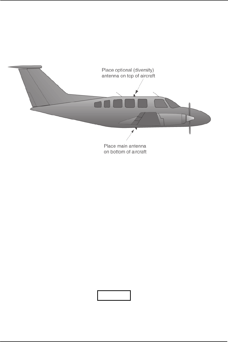
2.3.2 Antenna Location Considerations
Antenna mounting should utilize the aircraft manufacturer’s Type Certificated antenna location and style
of antenna. If a second (diversity) antenna is installed in the aircraft, considerations for its mounting
should be made as outlined in Figure 2-1. The antenna installation should be installed in accordance with
AC 43.12-2A Chapter 3. Note that penetration of the pressure vessel on the pressurized aircraft requires
additional data not contained in this manual. (See Section 2.5)
Figure 2-1 Antenna Installation Considerations
a. The antenna (Garmin P/N 010-10160-00 or equivalent) should be mounted away from major
protrusions, such as engine(s), propeller(s), and antenna masts. It should also be as far as
practical from landing gear doors, access doors, or other openings that could shadow (block)
the signal between the transponder antenna and ATC radar on TCAS.
b. The main antenna should be mounted vertically on the bottom of the aircraft (Figure 2-1).
The optional second (diversity) antenna should be mounted vertically on top of the aircraft.
Horizontal separation must be no more than 7.6 merers (25 feet).
c. Antenna Separation: DME and TCAS receive signals in the same frequency range that
aviation transponders transmit at, so their antennas should be separated from the transponder
antenna by as much as feasible. Six feet of separation is a guideline. Radar altimeters (should
one be installed on an aircraft with a GTX 3000) also have some potential to receive
interference from a transponder (the transponders’ fourth harmaonic), so it is good practice to
separate transponder and radar altimeter antennas by as much as practical also. Avoid
mounting the antenna within three feet of the ADF sense antenna or any other communication
antenna and six feet from the DME antenna.
d. To prevent RF interference, the antenna must be physically mounted a minimum distance of
three feet from the GTX 3000.
If the antenna is being installed on a composite aircraft, sufficient ground plane
material must be added. Conductive wire mesh, radials, or thin aluminum sheets
embedded in the composite material provide the proper ground plane allowing the
antenna gain pattern to be maximized for optimum transponder performance.
NOTE
DRAFT

Page 2-4 GTX 3000 Installation Manual
Revision A 190-00926-01
2.4 Cabling and Wiring
Refer to the interconnect examples in Appendix C for wire gauge guidance.
In some cases, a larger gauge wire such as AWG #18 may be needed for power connections. If using #18
barrel contacts, ensure that no two contacts are mounted directly adjacent to each other. This minimizes
the risk of contacts touching and shorting to adjacent pins or to ground.
Ensure that routing of the wiring does not come in contact with sources of heat, RF or EMI interference.
Check that there is ample space for the cabling and mating connectors. Avoid sharp bends in cabling and
routing near aircraft control cables. It is also good practice to avoid routing cables near sharp edges
because aircraft vibration might wear away the insulation on the wires, which will leave them exposed to
moisture and potentially create arcing or intermittent short circuits.
The maximum attenuation at 1090 MHz between the unit and the antenna must not exceed 3.0 dB. This
loss specification includes connector loss; for example, through a bulkhead connector (0.2 dB is typical
loss for each bulkhead connector). The GTX 3000 back-plate assembly utilizes a BNC-type (bayonet
connection) coaxial connector.
Table 2-5 lists examples of recommended antenna cable. Use the table to determine the length of cable
needed to connect the transponder to the antenna, and to look up a recommended cable manufacturer and
part number that will meet the 3.0 dB loss spec. The table assumes a loss figure of 0.2 dB per connector.
Note that any 50 Ω, double shielded coaxial cable assembly that meets airworthiness requirements and the
3.0 dB maximum loss figure (including connectors) may be used.
Differential cable loss: If the cable loss difference between top and bottom channels is less than 1 dB, the
unit’s default cable loss values are applicable, and the unit does not require cable loss configuration. If that
cable loss difference is more than 1 dB different between antennas, then cable loss configuration is
required..
Table 2-5 Cable Specifications
Max. Length
(feet – [m])
Insertion loss
(dB/100ft) ECS Type MIL-C-17 Type RG Type
17' 5.2" [4.40m] 18.0 M17/128-RG400 RG-400
17' 11.7" [5.48m] 14.45 3C142B
21' 7.8" [6.60m] 12.00 M17/112-RG304 RG-304
29' 6.7" [9.01m] 8.80 311601 M17/127-RG393 RG-393
36' 6.2" [11.13m] 7.12 311501
47' 4.9" [14.25m] 5.56 311201
71' 7.4" [21.83m] 3.63 310801
Supplier
Information
Vendor: Electronic
Cable Specialists
5300 W. Franklin Drive
Franklin, WI 53132
Tel: 800-327-9473
414-421-5300
Fax: 414-421-5301
www.ecsdirect.com
See current issue of
Qualified Products
List QPL-17.
RG types are
obsolete and are
shown for
reference only;
replaced by M17
type numbers.
DRAFT

GTX 3000 Installation Manual Page 2-5
190-00926-01 Revision A
The maximum one-way propagation delay through the cables must not be more than 125 ns. The
maximum difference in the one-way propagation delay between the top and bottom antenna cables must be
less than or equal to 75 ns. Use Table 2-6 to determine the maximum difference in length between the top
and bottom antenna cables.
Absolute cable delay: Each antenna cable must have less than 75 ns of delay. The 75 ns spec is for one-
way cable delay – not delay down the cable and back up it (which one might consider given the receive and
transmit functions). If you meet the 3 dB cable loss requirement, you’ll almost certainly meet the 75 ns
delay requirement.
Differential cable delay: If the cable delay difference between the two cables is less than 25 ns, the unit
does not require cable delay to be configured. The unit’s default values will suffice. Otherwise, we’ll
simply have to configure each channel’s cable delay.
* Maximum difference in cable length is limited by maximum cable length.
2.4.1 Cable Routing Considerations
When routing cables, observe the following precautions:
• All cable routing should be kept as short and as direct as practical.
• Avoid sharp bends to prevent insulation from being breached.
• Avoid routing close to sharp edges to prevent insulation from being breached due to vibration or
handling the cable.
• Avoid routing cables near power sources (e.g., 400 Hz generators, trim motors, etc.) or near power
for fluorescent lighting.
• Avoid routing antenna cables near DME, TCAS, radar altimeter, and ADF antenna cables (allow at
least a 12-inch separation).
Table 2-6 Maximum Difference in Cable Lengths
Max. Difference
in Length
(feet – [m])
Velocity of
Propagation
(ns/ft)
ECS Type MIL-C-17 Type RG Type
14' 5.2" [4.40m]* 1.46 M17/128-RG400 RG-400
17' 11.7" [5.48m]* 1.46 3C142B
21' 7.8" [6.60m]* 1.46 M17/112-RG304 RG-304
29' 6.7" [9.01m]* 1.25 311601 M17/127-RG393 RG-393
36' 6.2" [11.13m]* 1.25 311501
47' 4.9" [14.25m]* 1.25 311201
59' 11.7" [18.28m] 1.25 310801
DRAFT

Page 2-6 GTX 3000 Installation Manual
Revision A 190-00926-01
2.5 Installation Approval Considerations for Pressurized Aircraft
Antenna and cable installations on pressurized cabin aircraft require FAA approved installation design and
engineering substantiation data whenever such installations incorporate alteration (penetration) of the
cabin pressure vessel by connector holes and/or mounting arrangements. Use of existing bulkhead
connectors previously approved by other means is permissible without additional approval.
For needed engineering support pertaining to the design and approval of such pressurized aircraft antenna
installations, it is recommended that the installer proceed according to any of the following listed options:
1. Obtain approved antenna installation design data from the aircraft manufacturer.
2. Obtain an FAA approved Supplemental Type Certificate (STC) pertaining to and valid for
the subject antenna installation.
3. Contact the FAA Aircraft Certification Office in the appropriate Region and request
identification of FAA Designated Engineering Representatives (DERs) who are
authorized to prepare and approve the required antenna installation engineering data.
4. Obtain FAA Advisory Circular AC-183C and select (and contact) a DER from the roster
of individuals identified thereunder.
5. Contact an aviation industry organization such as the Aircraft Electronics Association and
request their assistance.
2.6 Cooling Air
Cooling air is generally not required. However, if the unit is located in a confined space or near a source of
heat, cooling air is recommended for maximizing the life of the GTX 3000. A 5/8 inch air fitting is
provided on the rear of the backplate for the purpose of admitting cooling air. If a form of forced air
cooling is installed, make certain that rainwater or condensation cannot enter and be sprayed on the
equipment.
2.7 GTX 3000 Mounting Requirements
Refer to the G1000 System Installation manual, Garmin part number 190-00303-00, for information on
cooling requirements. For remote mounted units, forced air cooling is not required. However, the
application of forced air cooling is recommended to provide beneficial cooling if the unit is located in a
confined space or near a source of heat.
A 5/8 inch air fitting is provided on the rear of the backplate for the purpose of admitting cooling air under
such conditions. If a form of forced air cooling is installed, make certain that rainwater or condensation
cannot enter and be sprayed on the equipment.
DRAFT
GTX 3000 Installation Manual Page 2-7
190-00926-01 Revision A
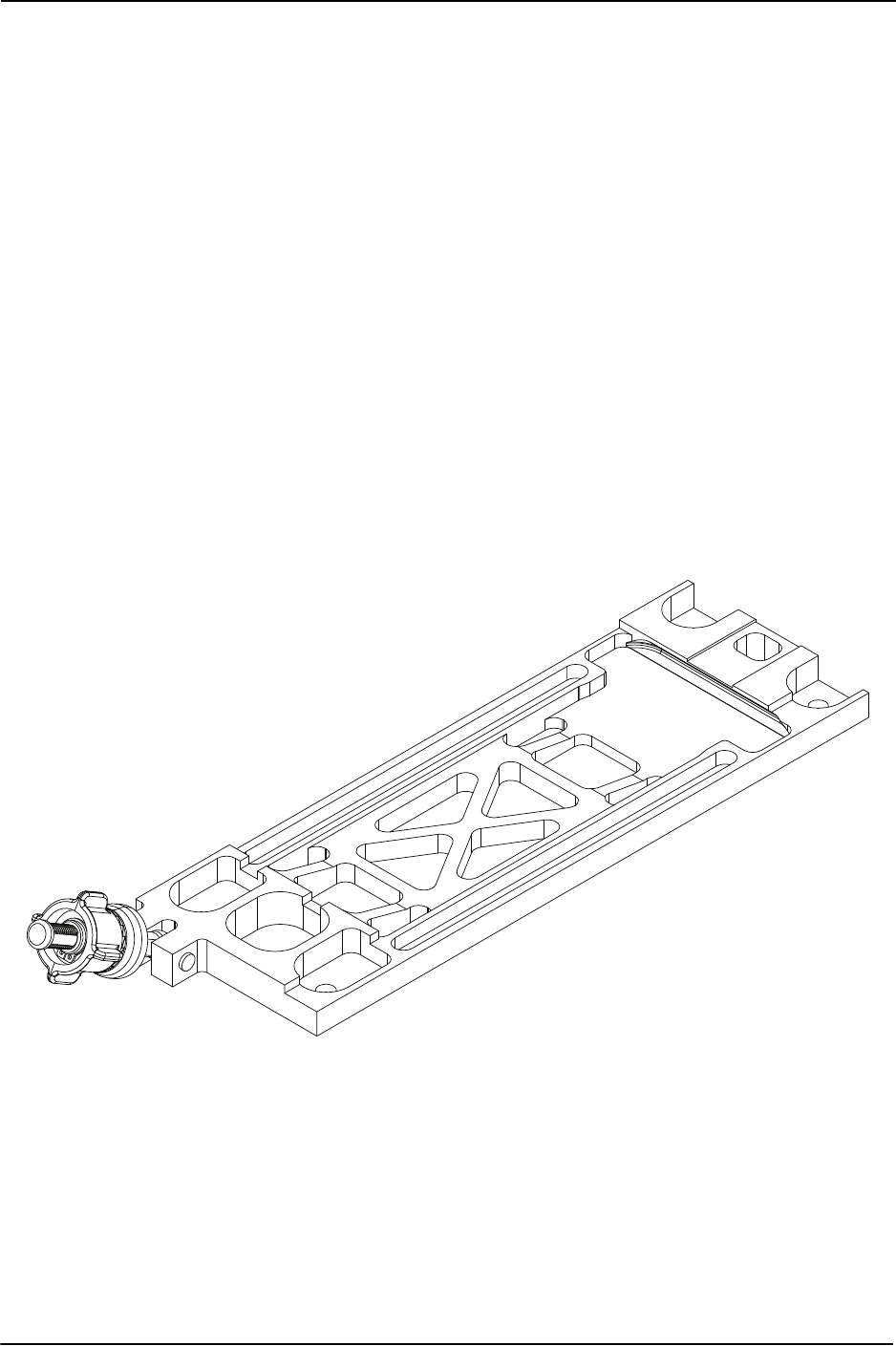
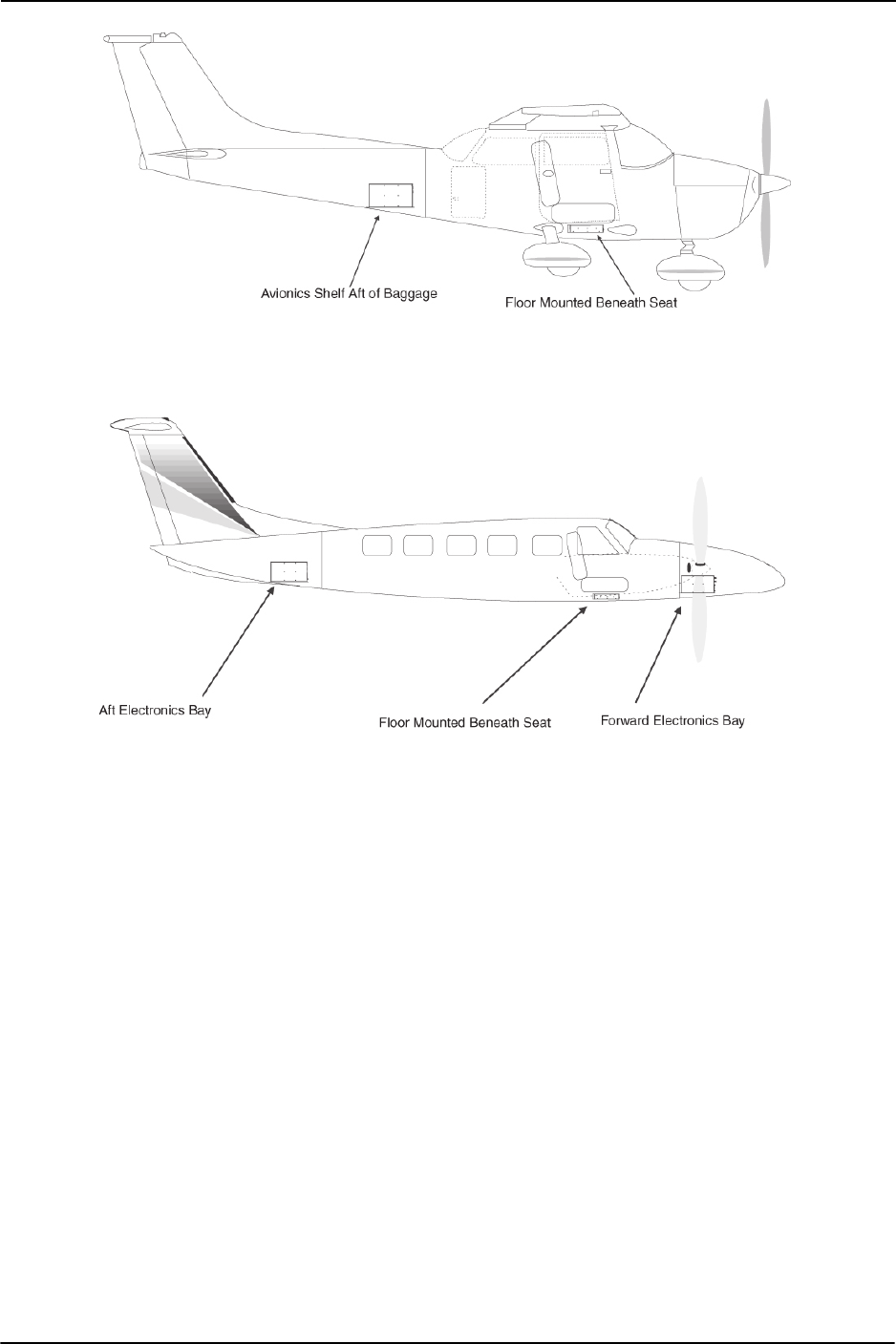
2.7.1 Remote Mounted Stand-Alone Rack Considerations
Figure 2-2 and the drawing in Appendix B show the GTX 3000 remote mounted stand-alone rack. The
remote rack can be installed in a variety of locations, such as the electronics bay, under a seat or on an
avionics shelf behind the rear baggage area. Refer to Figure 2-3 for suggested location. Leave sufficient
clearance between the GTX 3000 and any obstruction. Install the rack in accordance with AC 43.13-2A
Chapter 2 “Radio Installations”. The rack should be mounted to a surface known to have sufficient
structural integrity to withstand additional inertia forces imposed by a 4.3-pound (1.95 kg) unit. If it is
necessary to build a shelf or bracket to mount the GTX 3000 stand-alone rack or it is not certain that the
chosen location is of sufficient structural integrity, refer to Appendix A for validation of rack mounting
structures and determining static load capability.
Figure B-1 gives the GTX 3000 stand-alone rack dimensions. The rack can be mounted vertically using
four 8-32 pan head screws (MS35206, AN526 or other approved fastener). It can also be mounted
horizontally using four 6-32 100° counter-sunk flathead screws (MS24693, AN507R or other approved
fastener). Ensure that the GTX 3000 chassis has a ground path to the airframe by having at least one
mounting screw in contact with the airframe. If more water-resistance is desired, the rack should be
installed in the upright vertical orientation only, otherwise, the rack may be mounted in either vertical or
horizontal orientation.
After the cable assemblies are made and wiring installed to the rack back plate, route wiring bundle as
appropriate. Use cable ties to secure the cable assemblies and coax to provide strain relief for the cable
assemblies.
Figure 2-2 GTX 3000 Stand Rack (011-02515-00)
DRAFT
Page 2-8 GTX 3000 Installation Manual
Revision A 190-00926-01
Figure 2-3 GTX 3000 Rack, Suggested Mounting Locations
DRAFT
GTX 3000 Installation Manual Page 3-1
190-00926-01 Revision A
3 INSTALLATION PROCEDURE
3.1 Unpacking Unit
Carefully unpack the equipment and make a visual inspection of the unit for evidence of damage incurred
during shipment. If the unit is damaged, notify the carrier and file a claim. To justify a claim, save the
original shipping container and all packing materials. Do not return the unit to Garmin until the carrier has
authorized the claim.
Retain the original shipping containers for storage. If the original containers are not available, a separate
cardboard container should be prepared that is large enough to accommodate sufficient packing material to
prevent movement.
3.2 Wiring Harness Installation
Allow adequate space for installation of cables and connectors. The installer shall supply and fabricate all
cables. All electrical connections to the GTX 3000 are made through one 62-pin D-subminiature
connector and one 78-pin D-subminiature connector. Section 4 defines the electrical characteristics of all
input and output signals. Required connectors and associated hardware are supplied with the connector kit.
See Appendix C for examples of interconnect wiring diagrams. Construct the actual harnesses in
accordance with the aircraft manufacturer authorized interconnect standards.
Check wiring connections for errors before inserting the GTX 3000 into the rack.
Incorrect wiring could cause internal component damage.
CAUTION
Table 3-1: Pin Contact Part Numbers
Manufacturer
(Note 1)
62 pin D-Subminiature connector
(P3301)
18-20 AWG 22-28 AWG
Garmin P/N 336-00044-00 336-00021-00
Military P/N N/A M39029/58-360
AMP N/A 204370-2
Positronic N/A MC8522D
ITT Cannon N/A 030-2042-000
DRAFT

Page 3-2 GTX 3000 Installation Manual
Revision A 190-00926-01
1. Non-Garmin part numbers shown are not maintained by Garmin and consequently are subject to
change without notice.
2. Extracting the 18 AWG contacts requires that the expanded wire barrel be cut off from the
contact. It may also be necessary to push the pin out from the face of the connector when using
an extractor due to the absence of the wire. A new contact must be used when reassembling the
connector.
3.3 Backshell Assembly
The GTX 3000 connector kit includes two Garmin backshell assemblies. Garmin’s backshells give the
installer the ability to quickly and easily terminate shield grounds at the backshell housing using the Shield
Block grounding method.
G1000 Installations:
To assemble the backshell and grounding system, refer to the instructions provided in the G1000 System
Installation Manual (190-00303-00), as well as the Shield Block Installation Instructions (190-00313-09).
Non-G1000 Installations:
For GTX 3000 installations mounted as a remote transponder system, refer to the Shield Block Installation
Instructions (190-00313-09) for grounding instructions.
3.4 Weight and Balance
Weight and balance computation is required after the installation of the GTX 3000. Follow the guidelines
as established in AC 43.13-1B, Chapter 10, Section 2. Make appropriate entries in the equipment list
indicating items added, removed, or relocated along with the date accomplished. Include your name and
certificate number in the aircraft records. Section 1.5.1 identifies the weight of the new GTX 3000
equipment and the drawings in Appendix B show the center of gravity.
Table 3-2 Recommended Crimp Tools
Manufacturer
(Note 1)
Hand
Crimping Tool
18-20 AWG 22-28 AWG
Positioner
(Note 3)
Insertion/
Extraction Tool
(Note 2)
Positioner
Insertion/
Extraction
Tool
Military P/N M22520/2-01 N/A M81969/1-04 M22520/2-09 M81969/1-04
Positronic 9507 9502-11 M81969/1-04 9502-3 M81969/1-04
ITT Cannon 995-0001-584 N/A N/A 995-0001-739 N/A
AMP 601966-1 N/A 91067-1 601966-6 91067-1
Daniels AFM8 K774 M81969/1-04 K42 M81969/1-04
Astro 615717 N/A M81969/1-04 615725 M81969/1-04
NOTE
DRAFT
GTX 3000 Installation Manual Page 3-3
190-00926-01 Revision A
3.5 Electrical Load Analysis
An electrical load analysis should be completed on each aircraft prior to installation in accordance with
AC43.13-1B, Chapter 11. Use the following values for computation:
3.5.1 Circuit Breaker Placard
Install a Circuit Breaker Placard labeled Transponder or Transponder 1, Transponder 2 as appropriate as
indicated in AC 43.13-2A, paragraph 27c(4).
3.6 Final Installation
?????????????????????
3.7 Post Installation Configuration and Checkout
The GTX 3000 Mode S Transponder will not provide valid outputs until the
aircraft post installation configuration procedures are completed.
3.7.1 Configuration
When installed as part of the Garmin Integrated Flight Deck, the GTX 3000 transponder must have FAA
approved configuration data. Configuration data is loaded to the GTX 3000 from an aircraft-specific
Software Loader Card. Transponder settings are predetermined for a specific aircraft and are typically
contained within the file named ‘GTX1’. However, the aircraft registration number must be entered
manually.
The PFD serves as the graphics user interface to the installer configuring the system. For basic
configuration information, refer to the G1000 Line Maintenance and Configuration Manual, Garmin part
number 190-00303-04. For actual aircraft installation/checkout, use only aircraft manufacturer approved
checkout procedures.
Verify proper operation of the transponder by testing in accordance with Appendix F to 14 CFR Part 43 –
ATC Transponder Tests and Inspections.
For transponder installations operating with a Garmin GNS 480 (CNX80), refer to GNS 480 (CNX80)
Installation Manual, 560-0982-01 for configuration procedures and operation checks.
3.7.2 Interference Check
Turn on and verify operation of all avionics equipment except GTX 3000. Then power the GTX 3000 on
and verify there is no interference with any other equipment in the aircraft. The operation/performance
checks should be made with all other avionics turned on. Verify that there is no interference during any
mode of transponder operation.
Table 3-3 Unit Power Loads
GTX 3000 Input 14 Vdc 28 Vdc
Typical Max. Typical Max.
GTX 3000 Main Power 1.6 A 3.2 A 0.85 A 1.6 A
NOTE
DRAFT

Page 3-4 GTX 3000 Installation Manual
Revision A 190-00926-01
3.7.3 Operation/Performance Checkout.
If the unit is removed from the aircraft and operated, always connect J3303 and
J3303 to an antenna or a 50 Ω, 5-Watt load. The GTX 3000 transmits Mode S
acquisition squitter replies about once per second whether interrogations are
received or not.
Verify proper operation of the transponder by testing as specified in Appendix F of 14 CFR, Part 43, to
AC 43-6B, and/or other appropriate regulations. The test is typically done as a ramp test using a
transponder ramp test set, such as the TIC TR-220, IFR ATC-601 or other suitable Mode S transponder test
set.
Self Test
Verify that the unit does not display a failure indication when turned on.
Altitude Input
Verify that the displayed altitude matches the altimeter pressure altitude (at 29.92).
External Inputs
If the external ident or standby inputs are connected, verify operation by:
a) Verify that the unit goes to standby when the external standby input is pulled low.
b) Verify that the ident indication turns on when the external ident button is pressed (must
be in the “ON” or “ALT” modes).
3.7.4 Performance (Ramp) Test
After installation, the transponder should be tested as specified in 14 CFR Part 43 Appendix F, AC 43-6B,
and other appropriate regulations. The test is typically done as a ramp test using a transponder ramp test
set, such as the IFR ATC-601A. The ramp test includes checks as follows:
Reference Part 43 Appendix F:
a) Reply Frequency
b) Suppression
c) Receiver Sensitivity
d) Reply RF Output Power
e) Mode S Diversity Channel Isolation (if applicable)
f) Mode S Address
g) Mode S Formats
h) Mode S All-Call
i) ATCRBS –Only All Call
j) Squitter
Reference AC 43-6B and 14 CFR Part 43, Appendix E (c):
a) Altitude Reporting
3.8 Continued Airworthiness
Test according to Title 14 CFR §§ 91.411 and 91.413 as well as Part 43 Appendix F. Other than for
regulatory checks, maintenance of the GTX 3000 is ‘on condition’ only.
CAUTION
DRAFT

GTX 3000 Installation Manual Page 4-1
190-00926-01 Revision A
4 SYSTEM INTERCONNECTS
4.1 Pin Function List
4.1.1 P3301
Figure 4-1 View of J3301 connector, looking at unit
* Denotes Active Low (Ground to activate).
Table 4-1 P3301 Pin List
Pin Pin Name I/O
1 RESERVED [AVIONICS MASTER ON SELECT] --
2 ALTITUDE A1 In
3 ALTITUDE C2 In
4 ALTITUDE A2 In
5 ALTITUDE A4 In
6 ALTITUDE C4 In
7 ALTITUDE B1 In
8 ALTITUDE C1 In
9 ALTITUDE B2 In
10 ALTITUDE B4 In
11 ALTITUDE D4 In
12 EXTERNAL IDENT SELECT* In
13 EXTERNAL STANDBY SELECT* In
14 RESERVED [28V LIGHTING BUS HI] --
15 AUDIO OUT HI Out
16 AUDIO OUT LO Out
17 SQUAT SWITCH IN In
18 RESERVED [BOOT BLOCK SELECT] --
19 ALTITUDE ALERT ANNUNCIATE* Out
20 RESERVED [HIJACK MODE SELECT] --
21 RESERVED [AIRCRAFT POWER 1] --
22 RS-232 IN 1 In
23 RS-232 OUT 1 Out
24 RS-232 IN 2 In
25 RS-232 OUT 2 Out
26 ARINC 429 IN 3 A In
27 RESERVED [POWER GROUND] --
28 ARINC 429 OUT 2 B Out
29 ARINC 429 IN 3 B In
30 ARINC 429 OUT 2 A Out
31 EXTERNAL SUPPRESSION I/O I/O
123456789101112131415
222324252627282930313233343536
44464748495051
525354
5556
161718192021
373839404142
57
5859
6061
62
DRAFT

Page 4-2 GTX 3000 Installation Manual
Revision A 190-00926-01
Denotes Active Low (Ground to activate).
Table 4-1 P3301, Pin List continued
Pin Pin Name I/O
32 ARINC 429 IN 1 A In
33 ARINC 429 IN 2 A In
34 ARINC 429 OUT 1 B Out
35 ARINC 429 IN 1 B In
36 ARINC 429 IN 2 B In
37 ARINC 429 OUT 1 A Out
38 RESERVED [VOLTAGE TEMPERATURE PROBE OUT] --
39 RESERVED [VOLTAGE TEMPERATURE PROBE IN] --
40 GPS PPS IN 1 In
41 CURRENT TEMPERATURE PROBE OUT Out
42 RESERVED [AIRCRAFT POWER 1] --
43 RESERVED [POWER GROUND] --
44 CURRENT TEMPERATURE PROBE IN In
45 RESERVED [14V/5V LIGHTING BUS HI] --
46 TIS CONNECT SELECT* In
47 AUDIO MUTE SELECT* In
48 ARINC 429 IN 4 A In
49 ARINC 429 IN 4 B In
50 ALTITUDE COMMON (GROUND) In
51 RESERVED [SIGNAL GROUND] --
52 GPS PPS IN 2 HI In
53 GPS PPS IN 2 LO In
54 RESERVED [XPDR REMOTE POWER OFF] --
55 SPARE --
56 RESERVED [AIRCRAFT POWER 2] --
57 SPARE --
58 RESERVED [SIGNAL GROUND] --
59 SPARE --
60 RESERVED [AIRCRAFT POWER 2] --
61 XPDR FAIL* OUT 1 Out
62 RESERVED [SWITCHED POWER OUT] --
DRAFT

GTX 3000 Installation Manual Page 4-3
190-00926-01 Revision A
4.1.2 P3302
Figure 4-2 View of J3302 connector, looking at unit
*Denotes Active Low (Ground to activate).
Table 4-2 P3302 Pin List
Pin Pin Name I/O
1 CONFIG MODULE GROUND --
2 RESERVED [SIGNAL GROUND] --
3 AIRCRAFT POWER 1 In
4 RESERVED [SIGNAL GROUND] --
5 AIRCRAFT POWER 1 In
6 RESERVED [SIGNAL GROUND] --
7 AIRCRAFT POWER 2 In
8 RESERVED [SIGNAL GROUND] --
9 AIRCRAFT POWER 2 In
10 RESERVED [POWER GROUND] --
11 SWITCHED POWER OUT Out
12 ARINC 429 OUT 3 A Out
13 ARINC 429 OUT 3 B Out
14 ARINC 429 OUT 4 A Out
15 ARINC 429 OUT 4 B Out
16 RS-422 IN A In
17 RS-422 IN B In
18 RS-422 OUT A Out
19 RS-422 OUT B Out
20 XPDR FAIL* OUT 2 Out
21 CONFIG MODULE POWER OUT Out
22 RESERVED [SIGNAL GROUND] --
23 RESERVED [SIGNAL GROUND] --
24 RESERVED [SIGNAL GROUND] --
25 RESERVED [SIGNAL GROUND] --
26 RESERVED [SIGNAL GROUND] --
27 RESERVED [SIGNAL GROUND] --
28 RESERVED [SIGNAL GROUND] --
29 RESERVED [SIGNAL GROUND] --
30 ARINC 429 IN 5 A In
31 ARINC 429 IN 5 B In
1 2 3 4 5 6 7 8 9 10 11121314151617181920
21 22 23 24 25 26 27 28 29 30 31 32 33 34 35 36 37 38 39
40 41 42 43 44 45 46 47 48 49 50 51 52 53 54 55 56 57 58 59
60 61 62 63 64 65 66 67 68 69 70 71 72 73 74 75 76 77 78
DRAFT

Page 4-4 GTX 3000 Installation Manual
Revision A 190-00926-01
Table 4-2 P3302, Pin List continued
Pin Pin Name I/O
32 ARINC 429 IN 6 A In
33 ARINC 429 IN 6 B In
34 ARINC 429 IN 7 A In
35 ARINC 429 IN 7 B In
36 ARINC 429 IN 8 A In
37 ARINC 429 IN 8 B In
38 XPDR REMOTE POWER OFF In
39 RESERVED [SPARE DISCRETE OUT* 1] --
40 CONFIG MODULE DATA I/O
41 RESERVED [SIGNAL GROUND] --
42 SPARE --
43 SPARE --
44 SPARE --
45 SPARE --
46 SPARE --
47 SPARE --
48 SPARE --
49 SPARE --
50 SPARE --
51 SPARE --
52 SPARE --
53 SPARE --
54 RESERVED [SPARE DISCRETE IN* 1] --
55 RESERVED [SPARE DISCRETE IN* 2] --
56 RESERVED [SPARE DISCRETE IN* 3] --
57 RESERVED [SPARE DISCRETE IN* 4] --
58 XPDR REMOTE POWER ON* In
59 RESERVED [SPARE DISCRETE OUT* 2] --
60 CONFIG MODULE CLOCK Out
61 RESERVED [SIGNAL GROUND] --
62 POWER GROUND --
63 RESERVED [POWER GROUND] --
64 POWER GROUND --
65 RESERVED [POWER GROUND] --
66 RESERVED [SIGNAL GROUND] --
67 RESERVED [SIGNAL GROUND] --
DRAFT

GTX 3000 Installation Manual Page 4-5
190-00926-01 Revision A
*Denotes Active Low (Ground to activate).
4.2 Power Function
Power Input requirements are listed in the following tables. The power-input pins accept 14/28 Vdc.
Switched Power Out is a power source available for devices such as a remote digital altitude encoder.
Refer to Figure C-1 and C-2 for power interconnections.
4.2.1 Aircraft Power
*Denotes Active Low (Ground to activate).
Pin Pin Name I/O
68 RESERVED [SIGNAL GROUND] --
69 RESERVED [SIGNAL GROUND] --
70 RESERVED [SIGNAL GROUND] --
71 RESERVED [SIGNAL GROUND] --
72 RESERVED [SIGNAL GROUND] --
73 RESERVED [SIGNAL GROUND] --
74 RESERVED [SIGNAL GROUND] --
75 RESERVED [SIGNAL GROUND] --
76 RESERVED [SIGNAL GROUND] --
77 RESERVED [SIGNAL GROUND] --
78 RESERVED [SPARE DISCRETE OUT* 3] --
Table 4-3 Aircraft Power
Pin Name Connector Pin I/O
RESERVED [AIRCRAFT POWER 1] P3301 21 In
AIRCRAFT POWER 1 P3301 42 In
AIRCRAFT POWER 2 P3301 56 In
AIRCRAFT POWER 2 P3301 60 In
SWITCHED POWER OUT P3301 62 Out
RESERVED [POWER GROUND] P3301 27 --
POWER GROUND P3301 43 --
SIGNAL GROUND P3301 51 --
SIGNAL GROUND P3301 58 --
AIRCRAFT POWER 1 P3302 3 In
AIRCRAFT POWER 1 P3302 5 In
AIRCRAFT POWER 2 P3302 7 In
AIRCRAFT POWER 2 P3302 9 In
SWITCHED POWER OUT P3302 11 Out
RESERVED [POWER GROUND] P3302 10 --
RESERVED [POWER GROUND] P3302 63 --
RESERVED [POWER GROUND] P3302 65 --
Table 4-2 P3302, Pin List continued
DRAFT

Page 4-6 GTX 3000 Installation Manual
Revision A 190-00926-01
4.3 Altitude Functions
Altitude functions with pin assignments are shown for reference since the altitude function is available in
the GTX 3000. In the Garmin Integrated Flight Deck system, altitude data is received from the GIA 63 in
RS-232 format.
Parallel gray code altitude inputs are considered active if either the voltage to ground is < 1.9 V or the
resistance to ground is < 375 Ω. These inputs are considered inactive if the voltage to ground is 11-33 Vdc.
The GTX 3000 contains internal altitude code line isolation diodes to prevent the
unit from pulling the encoder lines to ground when the transponder is turned off.
If two separate altitude encoders are connected to the GTX 3000, one providing
parallel gray code and the other, serial data, the unit selects only one for use at a
time, with serial data input receiving the highest priority.
For altitude encoders that can be connected in both serial data and parallel gray
code format, such as the Garmin GAE 43 (Garmin P/N 013-00066-00), select one
or the other but not both wiring connections.
When connecting two altitude encoders to the Garmin GNS 480 (CNX80), the
unit can only receive serial data from one unit at a time. Use a DPDT switch to
connect both serial data and External Standby Select. Refer to Figure C-3.
Among the surveillance items the Mode S transponder will transmit to the ground stations and other
aircraft are altitude reporting in 25’ increments with the proper encoder. In order to report altitude in
25-foot increments the GTX 3000 must receive altitude from suitable altitude reporting devices through
serial input connections. Altitude input to the GTX 33 received from parallel wire gray code encoders is
supplied to the unit in 100-foot increments and thus reported in 100-foot increments.
4.3.1 Altimeter Inputs
4.3.2 Altimeter Interconnect, Dual GTX 3000 Installation
For complete dual installation in which digital altitude encoders are connected to the GTX 3000, it is best
to install two digital sources, connecting one encoder to each transponder.
NOTES
Table 4-4 Altimeter Inputs
Pin Name Connector Pin I/O
ALTITUDE A1 P3301 2 In
ALTITUDE A2 P3301 4 In
ALTITUDE A4 P3301 5 In
ALTITUDE B1 P3301 7 In
ALTITUDE B2 P3301 9 In
ALTITUDE B4 P3301 10 In
ALTITUDE C1 P3301 8 In
ALTITUDE C2 P3301 3 In
ALTITUDE C4 P3301 6 In
ALTITUDE D4 P3301 11 In
ALTITUDE COMMON (GROUND) P3301 50 In
DRAFT

GTX 3000 Installation Manual Page 4-7
190-00926-01 Revision A
4.3.3 Altimeter Selection Priority
When connecting the transponder to a GNS 480 (CNX80), the installer must be aware of the GTX 33
priority for selecting encoded altimeter interconnections. The GTX 33 searches in this sequence for
altitude, and stops when it finds a valid pressure altitude input.
Altitude reporting equipment order of precedence:
1) ARINC 429 Air Data Computer (label 203, if configured W/ALT) (25’)
2) ARINC 429 EFIS (label 203, if configured W/ALT) (25’)
3) RS-232 data from GNS 480 (CNX80), or Garmin Integrated Flight Deck (25')
4) RS-232 Fuel/Air Data Computer (if configured W/ALT.) (25’)
5) Shadin Altitude Serializer/Encoder (if configured for 25’)
6) Icarus Altitude Serializer/Encoder (if configured for 25’)
7) Parallel wire Gray Code input (100’)
8) Shadin Altitude Serializer/Encoder (if configured for 100’)
9) Icarus Altitude Serializer/Encoder (if configured for 100’)
Only approved devices may provide altitude to the GTX 33 in accordance with 14 CFR 91.217. In
addition, all altitude reporting devices installed in the aircraft must meet certification requirements of
14 CFR 91.413. The installer must select an altitude reporting device that is a certified altitude source for
the particular aircraft.
It is the installing agency’s responsibility to determine that the installed encoder is compatible with the
selected altitude reporting criteria, either 100’ or 25’. Refer to the GNS 480 (CNX80), installation manual
560-0982-01 for the altitude data reporting configuration.
For additional information, refer to GNS 480 (CNX80) Installation Manual 560-0982-01 for the altitude
data reporting configuration when connecting a GTX 330 to a GNS 480 (CNX80).
4.4 Discrete Functions
Discrete functions with pin assignments are shown for reference since the functions are available in the
GTX 3000. External suppression should be connected if another transponder or DME is installed in the
aircraft avionics system. Depending on system configuration, the Garmin Integrated Flight Deck may not
use these inputs, as many functions are received from the GIA 63 in RS-232 format.
4.4.1 Discrete Outputs
External suppression should be connected if a DME is installed in the aircraft avionics system. The
GTX 3000 suppression I/O pulses may not be compatible with all models of DME. Known incompatible
units include the Bendix/King KN 62, KN 64 and KNS 80. These models have an output-only suppression
port and can be damaged by the GTX 3000 mutual suppression output. In this case, leave the suppression
pin open.
*INACTIVE: 10 ≤ Vin ≤ 33VDC or Rin ≥100kΩ
ACTIVE: Vin ≤ 1.9VDC with ≥ 75 uA sink current, or Rin ≤ 375Ω
Sink current is internally limited to 200 uA max for a grounded input
Table 4-5 Discrete Outputs
Pin Name Connector Pin I/O
ALTITUDE ALERT ANNUNCIATE* P3301 19 Out
EXTERNAL SUPPRESSION I/O (TXP/DME) P3301 31 I/O
RESERVED [SIGNAL GROUND] P3301 51 --
RESERVED [SIGNAL GROUND] P3301 58 --
DRAFT

Page 4-8 GTX 3000 Installation Manual
Revision A 190-00926-01
4.4.2 Discrete Inputs
*INACTIVE: 10 ≤ Vin ≤ 33VDC or Rin ≥100kΩ
ACTIVE: Vin ≤ 1.9VDC with ≥ 75 uA sink current, or Rin ≤ 375Ω
Sink current is internally limited to 200 uA max for a grounded input
EXTERNAL IDENT SELECT (remote IDENT) is a momentary input. Refer to the GNS 480 (CNX80),
installation manual for the squat switch configuration.
EXTERNAL STANDBY SELECT (remote STANDBY) is a momentary input used when two GTX 33
systems are installed in an aircraft. Refer to Figure C-3, for the EXTERNAL STANDBY SELECT
interconnect. When EXTERNAL STANDBY SELECT is grounded, ARINC 429 OUT PORT 1 remains
active, while PORT 2 is inactive.
4.5 Serial Data Electrical Characteristics
The GTX 33 manages support for several equipment interfaces. The GTX 33 can be configured to include
GPS, Airdata, AHRS, EFIS/Airdata, and ADLP 429 inputs, functioning as an ARINC 429 data
concentrator.
The GTX 33 has four ARINC 429 input ports, making it capable of taking altitude, air data, heading, EFIS
selected course and possible future features, and then concentrating it on the ARINC 429 OUT 2 ports for
possible data link applications.
The GTX 33 is designed to feed all outgoing data to the external display via RS-232 data ports.
Table 4-6 Discrete Inputs
Pin Name Connector Pin I/O
EXTERNAL IDENT SELECT* P3301 12 In
EXTERNAL STANDBY SELECT* P3301 13 In
SQUAT SWITCH IN P3301 17 In
AUDIO MUTE SELECT* P3301 47 In
DRAFT

GTX 3000 Installation Manual Page 4-9
190-00926-01 Revision A
4.5.1 RS-232 Input/Output
The RS-232 outputs conform to EIA Standard RS-232C with an output voltage swing of at least ±5 V
when driving a standard RS-232 load. Refer to figures in Appendix C for the RS-232 serial data
interconnect.
When connecting two GTX 3000 transponders to a GPS, the unit can only receive RS-232 serial data from
one unit at a time. Use a DPDT switch for connecting both serial data and External Standby Select. Refer
to Figure C-4, Sheets 2 and 3.
4.5.2 RS-422 Input/Output
These data busses conform to EIA standard RS-422.
4.5.3 Configuration Module Connections
The configuration module, mounted in the J3302 connector backshell, contains an EEPROM.
Table 4-7 RS-232 Input/Output
Pin Name Connector Pin I/O
RS-232 IN 1 P3301 22 In
RS-232 OUT 1 P3301 23 Out
RS-232 IN 2 P3301 24 In
RS-232 OUT 2 P3301 25 Out
SIGNAL GROUND P3301 51 --
SIGNAL GROUND P3301 58 --
Table 4-8 RS-422 Input/Output
Pin Name Connector Pin I/O
RS-422 IN A P3302 16 In
RS-422 IN B P3302 17 In
RS-422 OUT A P3302 18 Out
RS-422 OUT B P3302 19 Out
SIGNAL GROUND P3302 --
SIGNAL GROUND P3302 --
Table 4-9 Configuration Module Connections
Pin Name Connector Pin I/O
CONFIG MODULE GROUND P3302 1 --
CONFIG MODULE POWER OUT P3302 21 Out
CONFIG MODULE DATA P3302 40 I/O
CONFIG MODULE CLOCK P3302 60 Out
DRAFT

Page 4-10 GTX 3000 Installation Manual
Revision A 190-00926-01
4.5.4 ARINC 429 Input/Output
The ARINC 429 outputs conform to ARINC 429 electrical specifications when loaded with up to five
standard ARINC 429 receivers.
Table 4-10 ARINC 429 Input/Output
Pin Name Connector Pin I/O
ARINC 429 IN 1A P3301 32 In
ARINC 429 IN 1B P3301 35 In
ARINC 429 OUT 1A P3301 37 Out
ARINC 429 OUT 1B P3301 34 Out
ARINC 429 IN 2A P3301 33 In
ARINC 429 IN 2B P3301 36 In
ARINC 429 OUT 2A P3301 30 Out
ARINC 429 OUT 2B P3301 28 Out
ARINC 429 IN 3A P3301 26 In
ARINC 429 IN 3B P3301 29 In
ARINC 429 IN 4A P3301 48 In
ARINC 429 IN 4B P3301 49 In
SIGNAL GROUND P3301 51 --
SIGNAL GROUND P3301 58 --
ARINC 429 OUT 3A P3302 12 Out
ARINC 429 OUT 3B P3302 13 Out
ARINC 429 OUT 4A P3302 14 Out
ARINC 429 OUT 4B P3302 15 Out
ARINC 429 IN 5A P3302 30 In
ARINC 429 IN 5B P3302 31 In
ARINC 429 IN 6A P3302 32 In
ARINC 429 IN 6B P3302 33 In
ARINC 429 IN 7A P3302 34 In
ARINC 429 IN 7B P3302 35 In
ARINC 429 IN 8A P3302 36 In
ARINC 429 IN 8B P3302 37 In
DRAFT

GTX 3000 Installation Manual Page 4-11
190-00926-01 Revision A
The following data is sent out at specified intervals using high speed ARINC 429 (100 kHz). The transmit
data labels and their rates are as follows:
4.6 RS-232 Input/Output, Software Update Connections
When the GTX 33 is installed in a system other than a Garmin Integrated Flight Deck an optional RS-232
serial data connector should be installed in the aircraft for future software upgrades, negating the need to
remove the transponder from the aircraft. The connector can be mounted anywhere convenient for access,
such as under the instrument panel, on a remote avionics shelf next to the unit or in the instrument panel
itself. Be sure to label the connector for Software Update. Do not include the Test Mode Select switch in
the aircraft. See Figure 4-3 for software update connections.
If the GTX 33 installation interfaces with a GNS 480 (CNX80) in the aircraft, the GNS 480 (CNX80) must
be turned off during GTX 330 software upload, due to loading of RS-232 port 1.
The installation of an optional software upgrade connector is highly
recommended. If the connector is wired in the aircraft, transponder removal and
reinstallation for software upgrade is not required.
If the unit is removed from the aircraft and operated, always connect J3302, (and
J3303 for GTX 33D) to an antenna or a 50 Ω, 5-Watt load. The GTX 33 transmits
Mode S acquisition squitter replies about once per second whether interrogations
are received or not.
Beginning with software version 3.06, the GTX 33 software can be updated in the Configuration mode as
well as in Test mode. Updating software in Configuration mode does not require the TEST MODE
SELECT switch.
Table 4-11 Transmit Data Labels
LABEL DATA RATE
100 Selected Course (degrees) 200 ms
203 Pressure Altitude [in feet set to 29.92” Hg (1013.25 mb)] 100 ms
204 Barometric Corrected Altitude (feet) 100 ms
206 Indicated Air Speed (knots) 100 ms
210 True Air Speed (knots) 100 ms
211 Total Air Temperature (degrees) 100 ms
213 Static Air Temperature (degrees) 100 ms
306 Joystick Lat 500 ms
307 Joystick Lon 500 ms
314 True Heading 100 ms
320 Magnetic Heading (Degrees) 100 ms
371 GA Equipment Identifier 500 ms
377 Equipment Identifier 500 ms
NOTE
CAUTION
DRAFT
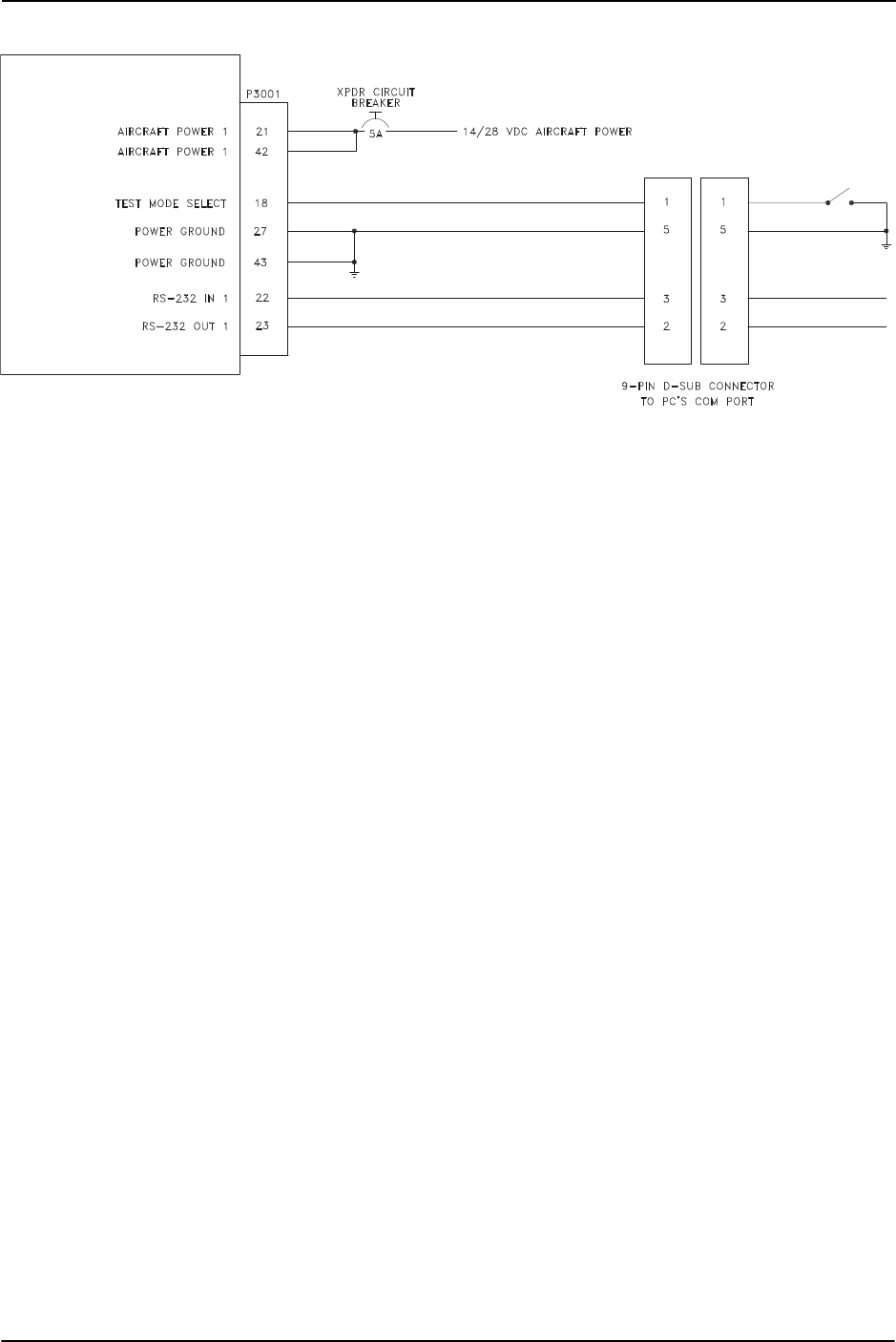
Page 4-12 GTX 3000 Installation Manual
Revision A 190-00926-01
Figure 4-3 GTX 3000 Software Update Connections
GTX 3000
DRAFT

GTX 3000 Installation Manual Page A-1
190-00926-01 Revision A
APPENDIX A Construction and Validation of Structures
A.1 Static Test Loading
This appendix includes information necessary for testing load-carrying capabilities of equipment mounting
structures, such as shelves, mounting plates and mounting brackets, used to mount the GTX 3000 remote
mounting tray.
Baggage compartments and cabins or cockpit floors are good mounting platforms providing the floor
attachments meet the strength requirements. If support racks, brackets or shelves need to be fabricated,
consider fabricating and attaching them to the aircraft structure in accordance with the methods outlined in
AC 43.13-2B Chapter 2. After the structure is installed, consider testing it as outlined in AC 43.13-2B
Chapter 1 to verify that it is capable of supporting the required loads.
The GTX 3000 installation must be capable of withstanding the Ultimate Load Factors listed in Table A-1
for at least 3 seconds in each direction specified without damage or permanent deformation. Note that
these required loads differ somewhat from those normally required for equipment installations.
Since the combined weight of the GTX 3000 and its equipment mounting rack and connector is 4.3 lbs, the
static loads which must be applied (Load Factor x 4.3 lbs.) will be as follows:
Table A-1 Static Test Load
A.2 Determining Static Load Capability
A recommended method of determining the static load capability is as follows:
1. Mark and drill the holes where the GTX 3000 equipment rack will be mounted.
2. Install four 8-32 machine screws (MS35206, AN526 or other approved fastener) in the four holes
which will be used to mount the GTX 3000 equipment rack using washers, nuts and nutplates to
mount the equipment rack to the mounting surface. Note that some means of locking fastener
must be used, e.g. either lock nuts or steel nuts with lock washers.
3. For testing downward loading, place shot bags or other suitable weights totaling 28.4 pounds
within the footprint outlined by the four screw holes (assuming the mounting surface is horizontal)
or use a calibrated force gauge at the location of the center of gravity when the unit is mounted.
4. Verify there is no damage or permanent deformation of the structure after 3 seconds.
5. Fasten a 36 inch loop of suitable material such as fishing line, braided wire, or other similar
material having a breaking strength of at least 100 lbs., diagonally between two of the screws.
Then fasten another loop diagonally between the other two screws, adjusting the length of the loop
so it exactly matches the first.
6. Hook a calibrated force gauge through both loops and apply a sustained pull for at least 3 seconds
in each of the other three directions (upward, sideward and forward) at the above calculated forces
(i.e. 25.8 lb. upward, 19.4 lb. sideward and 77.4 lb. forward).
Direction of Force Load Factor Static Test Load
(Load Factor x GTX 3000 weight)
DOWNWARD 6.6 G (6.6 x 4.3) = 28.4 lbs
UPWARD 6.0 G (6.0 x 4.3) = 25.8 lbs
SIDEWARD 4.5 G (4.5 x 4.3) = 19.4 lbs
FORWARD 18.0 G (18.0 x 4.3) = 77.4 lbs
DRAFT
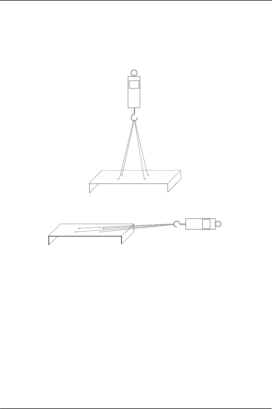
Page A-2 GTX 3000 Installation Manual
Revision A 190-00926-01
7. Examine the support structure carefully. If there has been damage or permanent deformation, the
structure is not suitable and must be replaced with one that is strong enough to withstand the test
loads. Examine all aircraft stringers, bulkheads and skin surfaces, which may have direct or
indirect contact with the fabricated shelf. If it is determined that no damage or permanent
deformation has occurred, the structure is of sufficient strength and the GTX 3000 equipment rack
may be permanently mounted on it.
Figure A-1 Upward static Load Test
Figure A-2 Forward Static Load Test
DRAFT
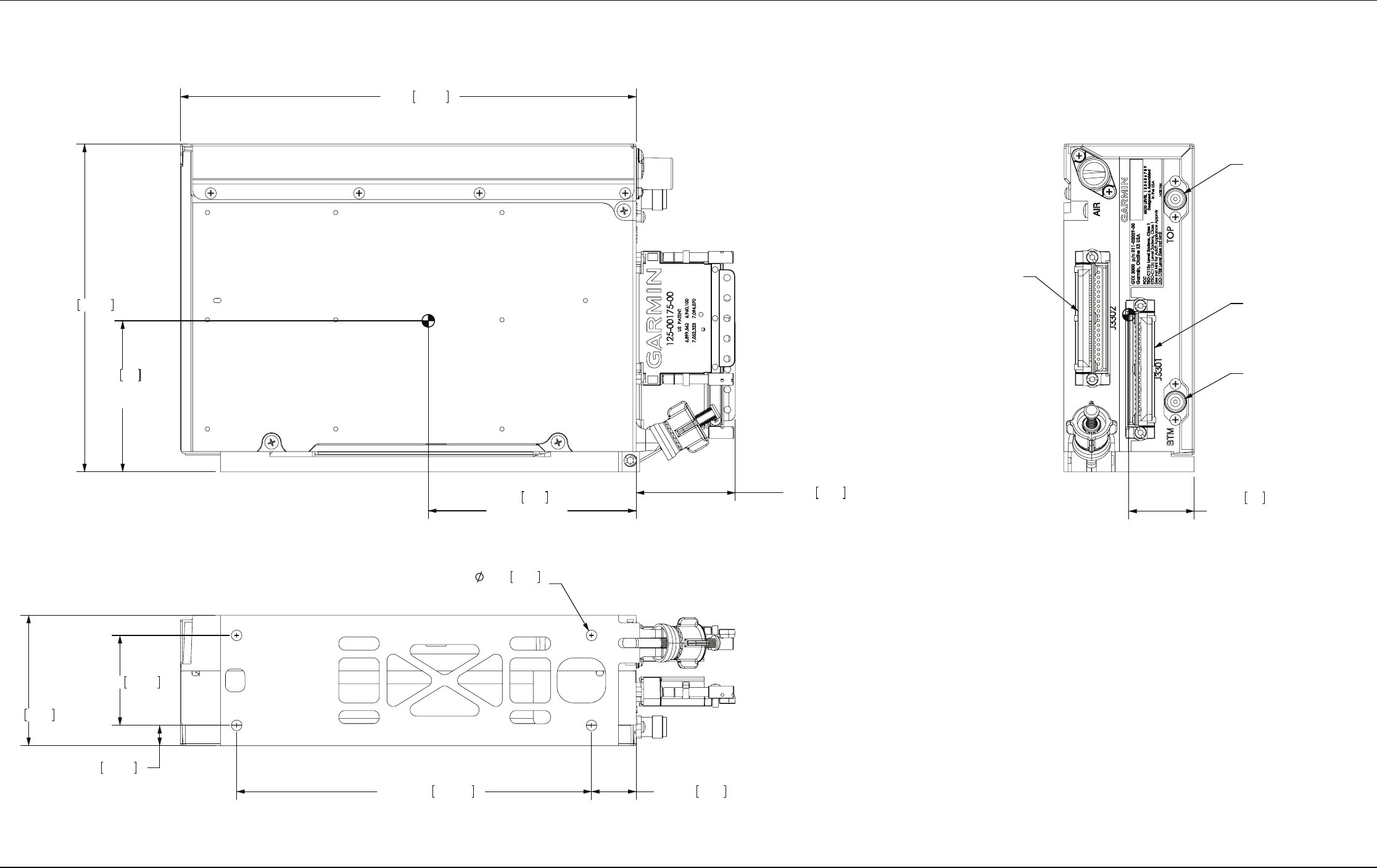
GTX 3000 Installation Manual Page B-1
190-00926-01 Revision A
APPENDIX B Assembly and Installation Drawings
Figure B-1 GTX 3000 Outline Drawing
4.1 104
CENTER
OF GRAVITY
3.0 76
CENTER
OF GRAVITY
1.3 33
CENTER
OF GRAVITY
NOTES:
DIMENSIONS: INCHES[mm].1.
DIMENSIONS ARE SHOWN FOR REFERENCE ONLY.2.
MOUNTING HOLES FOR #10 PANHEAD OR HEX HEAD FASTENERS (4 PLACES).3.
228.38.99
49.71.95
6.47 164.2
(TNC CONNECTOR)
P3301
P3302
BTM
(TNC CONNECTOR)
TOP
2X 1.775 45.09
.400 10.16
2X 7.000 .88 22.4177.80
2.58 65.4
2X
2X
4X .210 5.33
SEE NOTE 3
DRAFT
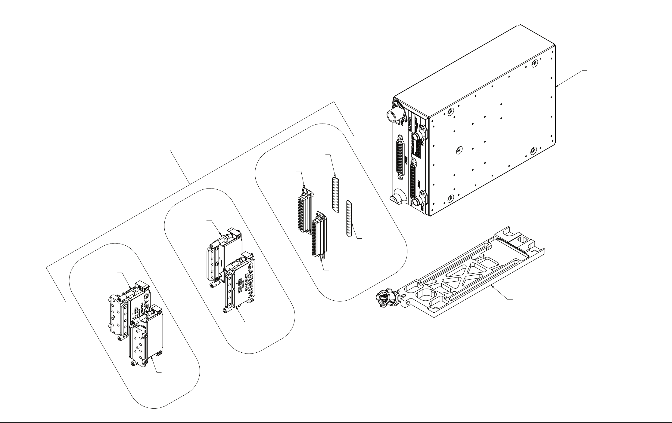
GTX 3000 Installation Manual Page B-2
190-00926-01 Revision A
APPENDIX B Assembly and Installation Drawings
Figure B-2 GTX 3000 Connector/Rack Assembly Drawing
CONNECTOR KIT
011-02019-XX (PARTS VARY DEPENDING ON SPECIFIC KIT)
CONFIGURATION MODULE (NOT SHOWN)
011-00979-20
011-01855-04
GTX 3000 RACK
(011-01997-00)
330-00776-62
GTX 3000 UNIT
(011-02515-00)
330-00776-78
011-01855-03
NOTES:
GASKETS ARE PART OF 330-00776-62 AND 330-00776-78. INSTALL GASKETS OVER PINS.1.
REFER TO 190-00313-11 FOR ADDITIONAL PARTS LISTS.2.
011-01959-03
NOTE 2
011-01959-04
NOTE 2
NOTE 1
NOTE 1
DRAFT
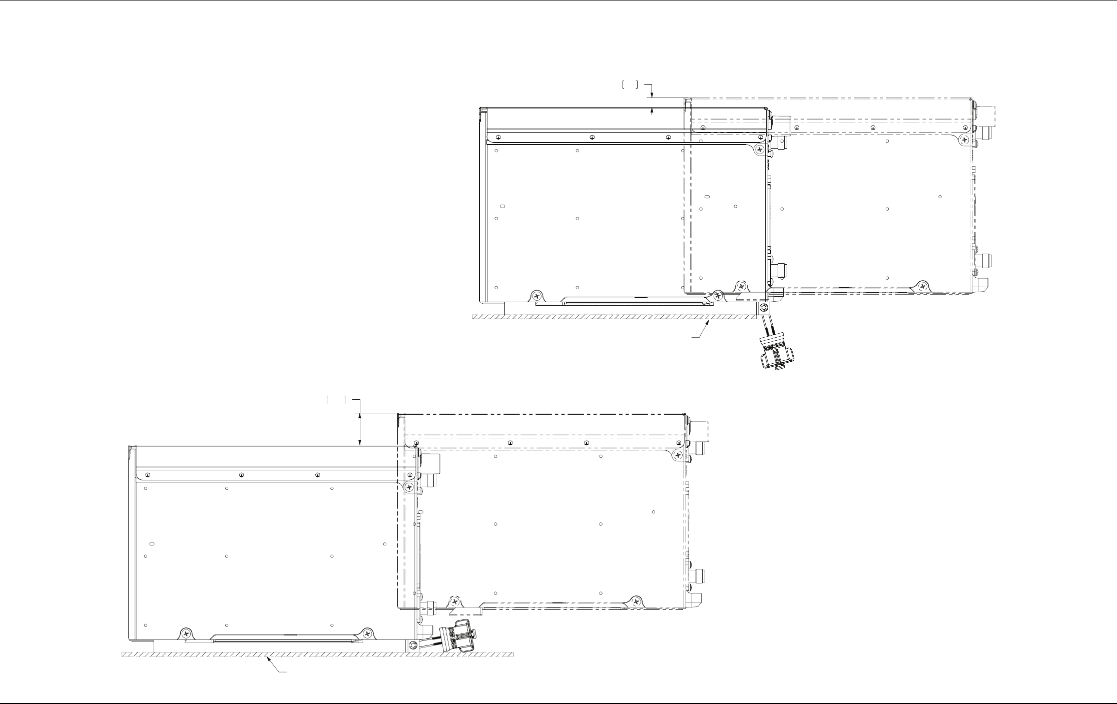
GTX 3000 Installation Manual Page B-3
190-00926-01 Revision A
APPENDIX B Assembly and Installation Drawings
Figure B-3 GTX 3000 Minimum Installation/Removal Clearance
MINIMUM REQUIRED INSTALLATION AND REMOVAL CLEARANCE
WITH LOCKDOWN OVERHANGING MOUNTING SHELF
MINIMUM RECOMMENDED INSTALLATION AND REMOVAL CLEARANCE
WITH LOCKDOWN NOT OVERHANGING MOUNTING SHELF
.30 7.6
MOUNTING SHELF
1.00 25.4
MOUNTING SHELF
DRAFT