Garmin 0163700 Spread Spectrum Digital Transmission 2402-2480 MHz User Manual
Garmin International Inc Spread Spectrum Digital Transmission 2402-2480 MHz
Garmin >
Contents
User Manual 1
Map
Traffic
Terrain
Weather
Procedures
Charts
Waypoint Info
Nearest
System
Services
Utilities
GTN 725/750
Pilot’s Guide
Flight Plan
190-01007-03-Final.indb 1 7/9/2015 2:06:43 PM

© 2015 Garmin Ltd. or its subsidiaries. All rights reserved.
This manual reflects the operation of System Software version , or later. Some differences in operation may
be observed when comparing the information in this manual to later software versions.
Garmin International, Inc., 1200 East 151st Street, Olathe, KS 66062, U.S.A.
Tel: 913/397.8200 Fax: 913/397.8282
Garmin AT, Inc., 2345 Turner Road SE, Salem, OR 97302, U.S.A.
Tel: 503/391.3411 Fax 503/364.2138
Garmin (Europe) Ltd., Liberty House, Bulls Copse Road, Hounsdown Business Park, Southampton,
SO40 9LR, U.K.
Tel. +44 (0) 87 0850 1243 Fax +44 (0) 23 8052 4004
Garmin Singapore Pte. Ltd., 46 East Coast Road, #05-06 Eastgate, Singapore 428766
Tel : (65) 63480378 Fax : ( 65 ) 63480278
At Garmin, we value your opinion. For comments about this guide, please e-mail:
Techpubs.Salem@Garmin.com
www.garmin.com
Except as expressly provided herein, no part of this manual may be reproduced, copied, transmitted, disseminated,
downloaded or stored in any storage medium, for any purpose without the express written permission of Garmin.
Garmin hereby grants permission to download a single copy of this manual and of any revision to this manual onto a
hard drive or other electronic storage medium to be viewed for personal use, provided that such electronic or printed
copy of this manual or revision must contain the complete text of this copyright notice and provided further that any
unauthorized commercial distribution of this manual or any revision hereto is strictly prohibited.
This part shall comply with Garmin Banned and Restricted Substances document, 001-00211-00.
Garmin
®
, FliteCharts
®
, and SafeTaxi
®
are registered trademarks of Garmin Ltd. or its subsidiaries. Garmin SVT™ and
Smart Airspace™ are trademarks of Garmin Ltd. or its subsidiaries. These trademarks may not be used without the
express permission of Garmin.
NavData
®
is a registered trademark of Jeppesen, Inc.; StormScope
®
and SkyWatch
®
are registered trademarks of L-3
Communications; Sirius and XM are trademarks of SiriusXM Radio Inc.; Iridium
®
is a registered trademark of Iridium
Communications Inc.; United States radar data provided by NOAA; European radar data collected and provided by
Meteo France. SD and SDHC Logos are trademarks of SD-3C, LLC; the Bluetooth
®
word mark and logos are registered
trademarks owned by Bluetooth SIG, Inc. and any use of such marks by Garmin is under license.
!UGUST 2015 Printed in the U.S.A.
190-01007-03-Final.indb 2 /2015 2:06:43 PM

i190-01007-03 Rev. J
Garmin GTN 725/750 Pilot’s Guide
Foreword
Getting
Started
Audio &
Xpdr Ctrl
Com/Nav
FPL
Direct-To
Proc
Charts
Wpt Info
Map
Traffic
Terrain
Weather
Nearest
Services/
Music
Utilities
System
Messages
Symbols
Appendix
Index
LIMITED WARRANTY
All Garmin avionics products are warranted to be free from defects in materials or workmanship for:
two years from the date of purchase for new Remote-Mount and Panel-Mount products; one year
from the date of purchase for new portable products and any purchased newly-overhauled products;
six months for newly-overhauled products exchanged through a Garmin Authorized Service Center;
and 90 days for factory repaired or newly-overhauled products exchanged at Garmin in lieu of repair.
Within the applicable period, Garmin will, at its sole option, repair or replace any components that
fail in normal use. Such repairs or replacement will be made at no charge to the customer for parts
or labor, provided that the customer shall be responsible for any transportation cost. This warranty
does not apply to: (i) cosmetic damage, such as scratches, nicks and dents; (ii) consumable parts,
such as batteries, unless product damage has occurred due to a defect in materials or workmanship;
(iii) damage caused by accident, abuse, misuse, water, flood, fire, or other acts of nature or external
causes; (iv) damage caused by service performed by anyone who is not an authorized service
provider of Garmin; or (v) damage to a product that has been modified or altered without the written
permission of Garmin. In addition, Garmin reserves the right to refuse warranty claims against
products or services that are obtained and/or used in contravention of the laws of any country.
THE WARRANTIES AND REMEDIES CONTAINED HEREIN ARE EXCLUSIVE AND IN LIEU OF ALL OTHER
WARRANTIES, WHETHER EXPRESS, IMPLIED OR STATUTORY, INCLUDING ANY LIABILITY ARISING
UNDER ANY WARRANTY OF MERCHANTABILITY OR FITNESS FOR A PARTICULAR PURPOSE,
STATUTORY OR OTHERWISE. THIS WARRANTY GIVES YOU SPECIFIC LEGAL RIGHTS, WHICH MAY
VARY FROM STATE TO STATE.
IN NO EVENT SHALL GARMIN BE LIABLE FOR ANY INCIDENTAL, SPECIAL, INDIRECT OR
CONSEQUENTIAL DAMAGES, WHETHER RESULTING FROM THE USE, MISUSE OR INABILITY TO USE
THE PRODUCT OR FROM DEFECTS IN THE PRODUCT. SOME STATES DO NOT ALLOW THE EXCLUSION
OF INCIDENTAL OR CONSEQUENTIAL DAMAGES, SO THE ABOVE LIMITATIONS MAY NOT APPLY TO
YOU.
Garmin retains the exclusive right to repair or replace (with a new or newly-overhauled replacement
product) the product or software or offer a full refund of the purchase price at its sole discretion.
SUCH REMEDY SHALL BE YOUR SOLE AND EXCLUSIVE REMEDY FOR ANY BREACH OF WARRANTY.
Online Auction Purchases: Products purchased through online auctions are not eligible for
warranty coverage. Online auction confirmations are not accepted for warranty verification. To obtain
warranty service, an original or copy of the sales receipt from the original retailer is required. Garmin
will not replace missing components from any package purchased through an online auction.
International Purchases: A separate warranty may be provided by international distributors for
devices purchased outside the United States depending on the country. If applicable, this warranty is
provided by the local in-country distributor and this distributor provides local service for your device.
Distributor warranties are only valid in the area of intended distribution. Devices purchased in the
United States or Canada must be returned to the Garmin service center in the United Kingdom, the
United States, Canada, or Taiwan for service.
To obtain warranty service, contact your local Garmin Authorized Service Center. For assistance in
locating a Service Center near you, visit the Garmin web site at http://www.garmin.com or contact
Garmin Customer Service at 866-739-5687.
190-01007-03-Final.indb 1 7/9/2015 2:06:43 PM
ii
Garmin GTN 725/750 Pilot’s Guide
190-01007-03 Rev. J
Foreword
Getting
Started
Audio &
Xpdr Ctrl
Com/Nav
FPL
Direct-To
Proc
Charts
Wpt Info
Map
Traffic
Terrain
Weather
Nearest
Services/
Music
Utilities
System
Messages
Symbols
Appendix
Index
WARNING: Navigation and terrain separation must NOT be predicated
upon the use of the terrain function. The GTN 725/750 Terrain Proximity
feature is NOT intended to be used as a primary reference for terrain
avoidance and does not relieve the pilot from the responsibility of being
aware of surroundings during flight. The Terrain Proximity feature is only
to be used as an aid for terrain avoidance and is not certified for use in
applications requiring a certified terrain awareness system. Terrain data
is obtained from third party sources. Garmin is not able to independently
verify the accuracy of the terrain data.
WARNING: The displayed minimum safe altitudes (MSAs) are only advisory
in nature and should not be relied upon as the sole source of obstacle and
terrain avoidance information. Always refer to current aeronautical charts
for appropriate minimum clearance altitudes.
WARNING: The Garmin GTN 725/750 has a very high degree of functional
integrity. However, the pilot must recognize that providing monitoring
and/or self-test capability for all conceivable system failures is not
practical. Although unlikely, it may be possible for erroneous operation
to occur without a fault indication shown by the GTN 725/750. It is thus
the responsibility of the pilot to detect such an occurrence by means of
cross-checking with all redundant or correlated information available in
the cockpit.
WARNING: The altitude calculated by GPS receivers is geometric height
above Mean Sea Level and could vary significantly from the altitude
displayed by pressure altimeters, such as the output from the GDC 74A/B
Air Data Computer, or other altimeters in aircraft. GPS altitude should never
be used for vertical navigation. Always use pressure altitude displayed by
pressure altimeters in the aircraft.
WARNING: Do not use outdated database information. Databases used
in the GTN 725/750 system must be updated regularly in order to ensure
that the information remains current. Pilots using an outdated database
do so entirely at their own risk.
WARNING: Do not use basemap (land and water data) information for
primary navigation. Basemap data is intended only to supplement other
approved navigation data sources and should be considered as an aid to
enhance situational awareness.
190-01007-03-Final.indb 2 7/9/2015 2:06:44 PM
iii190-01007-03 Rev. J
Garmin GTN 725/750 Pilot’s Guide
Foreword
Getting
Started
Audio &
Xpdr Ctrl
Com/Nav
FPL
Direct-To
Proc
Charts
Wpt Info
Map
Traffic
Terrain
Weather
Nearest
Services/
Music
Utilities
System
Messages
Symbols
Appendix
Index
WARNING: Traffic information shown on the GTN 725/750 is provided as
an aid in visually acquiring traffic. Pilots must maneuver the aircraft based
only upon ATC guidance or positive visual acquisition of conflicting traffic.
WARNING: Do not use data link weather information for maneuvering in,
near, or around areas of hazardous weather. Information contained within
data link weather products may not accurately depict current weather
conditions.
WARNING: Do not use the indicated data link weather product age to
determine the age of the weather information shown by the data link
weather product. Due to time delays inherent in gathering and processing
weather data for data link transmission, the weather information shown by
the data link weather product may be significantly older than the indicated
weather product age.
WARNING: For safety reasons, GTN 725/750 operational procedures must
be learned on the ground.
WARNING: To reduce the risk of unsafe operation, carefully review and
understand all aspects of the GTN 725/750 Pilot’s Guide. Thoroughly
practice basic operation prior to actual use. During flight operations,
carefully compare indications from the GTN 725/750 to all available
navigation sources, including the information from other NAVAIDs, visual
sightings, charts, etc. For safety purposes, always resolve any discrepancies
before continuing navigation.
CAUTION: The United States government operates the Global Positioning
System and is solely responsible for its accuracy and maintenance. The
GPS system is subject to changes which could affect the accuracy and
performance of all GPS equipment. Portions of the Garmin GTN 725/750
utilize GPS as a precision electronic NAVigation AID (NAVAID). Therefore,
as with all NAVAIDs, information presented by the GTN 725/750 can be
misused or misinterpreted and, therefore, become unsafe.
190-01007-03-Final.indb 3 7/9/2015 2:06:44 PM
iv
Garmin GTN 725/750 Pilot’s Guide
190-01007-03 Rev. J
Foreword
Getting
Started
Audio &
Xpdr Ctrl
Com/Nav
FPL
Direct-To
Proc
Charts
Wpt Info
Map
Traffic
Terrain
Weather
Nearest
Services/
Music
Utilities
System
Messages
Symbols
Appendix
Index
CAUTION: The Garmin GTN 725/750 does not contain any user-serviceable
parts. Repairs should only be made by an authorized Garmin service center.
Unauthorized repairs or modifications could void both the warranty and
the pilot’s authority to operate this device under FAA/FCC regulations.
CAUTION: The GTN displays use a lens coated with a special anti-reflective
coating that is very sensitive to skin oils, waxes, and abrasive cleaners.
CLEANERS CONTAINING AMMONIA WILL HARM THE ANTI-REFLECTIVE
COATING. It is very important to clean the lens using a clean, lint-free cloth and
an eyeglass lens cleaner that is specified as safe for anti-reflective coatings.
NOTE: Do not rely solely upon data link services to provide Temporary Flight
Restriction (TFR) information. Always confirm TFR information through
official sources such as Flight Service Stations or Air Traffic Control.
NOTE: All visual depictions contained within this document, including
screen images of the GTN bezel and displays, are subject to change and
may not reflect the most current GTN software. Depictions of equipment
may differ slightly from the actual equipment.
NOTE: This device complies with part 15 of the FCC Rules. Operation is
subject to the following two conditions: (1) this device may not cause
harmful interference, and (2) this device must accept any interference
received, including interference that may cause undesired operation.
NOTE: This product, its packaging, and its components contain chemicals
known to the State of California to cause cancer, birth defects, or reproductive
harm. This notice is being provided in accordance with California’s Proposition
65. If you have any questions or would like additional information, please
refer to our web site at www.garmin.com/prop65.
NOTE: Canadian installations: In accordance with Canadian Radio
Specifications Standard 102 (RSS 102), RF field strength exposure to
persons from an antenna connected to this device should be limited to 60
V/m for controlled environment and 28 V/m for uncontrolled environment.
NOTE: Do not use SafeTaxi or Chartview functions as the basis for
ground maneuvering. SafeTaxi and Chartview functions have not been
qualified to be used as an airport moving map display (AMMD). SafeTaxi
and Chartview are intended to improve pilot situational awareness
during ground operations should only be used by the flight crew to
orient themselves on the airport surface.
190-01007-03-Final.indb 4 7/9/2015 2:06:44 PM
v190-01007-03 Rev. J
Garmin GTN 725/750 Pilot’s Guide
Foreword
Getting
Started
Audio &
Xpdr Ctrl
Com/Nav
FPL
Direct-To
Proc
Charts
Wpt Info
Map
Traffic
Terrain
Weather
Nearest
Services/
Music
Utilities
System
Messages
Symbols
Appendix
Index
NOTE: The FAA has asked Garmin to remind pilots who fly with Garmin
database-dependent avionics of the following:
• It is the pilot’s responsibility to remain familiar with all FAA regulatory
and advisory guidance and information related to the use of databases in
the National Airspace System.
• Garmin equipment will only recognize and use databases that are
obtained from Garmin or Jeppesen. Databases obtained from Garmin
or Jeppesen are assured compliance with all data quality requirements
(DQRs) by virtue of a Type 2 Letter of Authorization (LOA) from the FAA. A
copy of the Type 2 LOA is available for each database and can be viewed
at http://fly.garmin.com by selecting "Type 2 LOA Status."
• Use of a current Garmin or Jeppesen database in your Garmin equipment
is required for compliance with established FAA regulatory guidance, but
does not constitute authorization to fly any and all terminal procedures
that may be presented by the system. It is the pilot’s responsibility to
operate in accordance with established AFM(S) and regulatory guidance
or limitations as applicable to the pilot, the aircraft, and installed
equipment.
NOTE: The pilot/operator must review and be familiar with Garmin’s
database exclusion list as discussed in SAIB CE-14-04 to determine what
data may be incomplete. The database exclusion list can be viewed at
www.flygarmin.com by selecting "Database Exclusions List."
NOTE: The pilot/operator must have access to Garmin and Jeppesen
database alerts and consider their impact on the intended aircraft
operation. The database alerts can be viewed at www.flygarmin.com by
selecting "Aviation Database Alerts."
NOTE: If the pilot/operator wants or needs to adjust the database, contact
Garmin Product Support.
NOTE: Garmin requests the flight crew report any observed discrepancies
related to database information. These discrepancies could come in the
form of an incorrect procedure; incorrectly identified terrain, obstacles and
fixes; or any other displayed item used for navigation or communication in
the air or on the ground. Go to FlyGarmin.com and select "Aviation Data
Error Report."
190-01007-03-Final.indb 5 7/9/2015 2:06:44 PM
vi
Garmin GTN 725/750 Pilot’s Guide
190-01007-03 Rev. J
Foreword
Getting
Started
Audio &
Xpdr Ctrl
Com/Nav
FPL
Direct-To
Proc
Charts
Wpt Info
Map
Traffic
Terrain
Weather
Nearest
Services/
Music
Utilities
System
Messages
Symbols
Appendix
Index
NOTE: The GTN touchscreen may not respond to touch commands if
condensation or moisture accumulate on the touchscreen.
NOTE: This device complies with Part 15 of
the FCC limits for Class B digital devices. This
equipment generates, uses, and can radiate
radio frequency energy and, if not installed
and used in accordance with the instructions,
may cause harmful interference to radio
communications. Furthermore, there is no
guarantee that interference will not occur in a
particular installation.
If this equipment does cause harmful
interference, the user is encouraged to try
to correct the interference by relocating the
equipment or connecting the equipment to a
different circuit than the affected equipment.
Consult an authorized dealer or other qualified
avionics technician for additional help if these
remedies do not correct the problem.
Operation of this device is subject to the
following conditions: (1) This device may
not cause harmful interference, and (2) this
device must accept any interference received,
including interference that may cause undesired
operation.
To obtain accessories for your unit, please
contact your Garmin dealer.
Help us better support you by completing our
on-line registration form today! Registration
ensures that you will be notified of product
updates and new products and provides lost
or stolen unit tracking. Please, have the serial
number of your unit handy, connect to our
web site (www.garmin.com) and look for our
Product Registration link on the Home page.
The display surface is coated with a special
anti-reflective coating which is very sensitive to
skin oils, waxes and abrasive cleaners. It is very
important to clean the lens using an eyeglass
lens cleaner which is specified as safe for anti-
reflective coatings and a clean, lint-free cloth.
AC 90-100A Statement of Compliance:
The Garmin navigational unit meets the
performance and functional requirements of
AC 90-100A.
190-01007-03-Final.indb 6 7/9/2015 2:06:44 PM
vii190-01007-03 Rev. J
Garmin GTN 725/750 Pilot’s Guide
Foreword
Getting
Started
Audio &
Xpdr Ctrl
Com/Nav
FPL
Direct-To
Proc
Charts
Wpt Info
Map
Traffic
Terrain
Weather
Nearest
Services/
Music
Utilities
System
Messages
Symbols
Appendix
Index
Product Registration and Support
Help us better support you by completing your online registration today!
Have the serial number of your product handy and connect to the Garmin web
site (www.garmin.com). Look for the Product Registration link on the Home
page. Also, be sure to record your serial number in the space provided.
If you have any questions, the Garmin Product Support department may be
reached Monday through Friday, 7:00 AM to 7:00 PM Central Time.
US: 913-397-8200
US Toll Free: 1-866-739-5687
Canada Toll Free: 1-866-429-9296
Record of Revisions
Part Number Revision Date Description
190-01007-03 1
A
B
C
D
E
F
G
H
J
01/24/11
02/04/11
03/16/11
11/29/12
02/28/13
03/25/13
08/26/13
08/01/14
10/17/14
7/2015
Initial Release
Production Release
Update information
Updates for software version 3.0
Updates for software version 4.0
Updates for software version 4.10
Updates for software version 5.0
Updates for software version 5.11
Updates for software version 5.12
Updates for software version 6.00
190-01007-03-Final.indb 7 7/9/2015 2:06:44 PM

viii
Garmin GTN 725/750 Pilot’s Guide
190-01007-03 Rev. J
Foreword
Getting
Started
Audio &
Xpdr Ctrl
Com/Nav
FPL
Direct-To
Proc
Charts
Wpt Info
Map
Traffic
Terrain
Weather
Nearest
Services/
Music
Utilities
System
Messages
Symbols
Appendix
Index
This page intentionally left blank
190-01007-03-Final.indb 8 7/9/2015 2:06:44 PM

ix190-01007-03 Rev. J
Garmin GTN 725/750 Pilot’s Guide
Foreword
Getting
Started
Audio &
Xpdr Ctrl
Com/Nav
FPL
Direct-To
Proc
Charts
Wpt Info
Map
Traffic
Terrain
Weather
Nearest
Services/
Music
Utilities
System
Messages
Symbols
Appendix
Index
Table of Contents
LIMITED WARRANTY ......................................................................................... i
Product Registration and Support ....................................................................vii
Welcome ..................................................................................................... xxvii
About This Guide ......................................................................................... xxvii
Electronic Document Features ...................................................................... xxvii
Conventions ............................................................................................... xxviii
1 Getting Started ................................................................................... 1-1
1.1 Model Descriptions ..............................................................................1-1
1.1.1 GTN 725 .............................................................................. 1-1
1.1.2 GTN 750 .............................................................................. 1-2
1.2 About This Pilot’s Guide .......................................................................1-2
1.2.1 Conventions ......................................................................... 1-2
1.2.2 Using the Touchscreen .......................................................... 1-2
1.3 Product Description ..............................................................................1-3
1.3.1 Secure Data Card ................................................................. 1-4
1.3.1.1 Inserting an SD Card .........................................................1-4
1.3.2 Pilot Controls ....................................................................... 1-4
1.3.2.1 Volume/Squelch Knob ........................................................... 1-4
1.3.2.2 Large/Small Concentric Knobs ............................................... 1-5
1.3.2.3 HOME Key ............................................................................ 1-5
1.3.2.4 Direct-To Key ........................................................................ 1-5
1.3.2.5 Touchscreen Keys ................................................................. 1-6
1.4 Unit Power Up .....................................................................................1-6
1.4.1 Start-Up Screens ................................................................... 1-6
1.4.2 Database Verification and Fuel Settings ................................. 1-7
1.5 System Operation...............................................................................1-11
1.5.1 Using the Touchscreen Key Controls .................................... 1-11
1.5.2 System Page ....................................................................... 1-11
1.5.2.1 System Setup Values ........................................................... 1-12
1.5.2.2 Units Settings Values .......................................................... 1-13
1.5.2.3 Alerts Settings Values ......................................................... 1-13
1.5.2.4 Audio Values ...................................................................... 1-13
1.5.2.5 Backlight Values ................................................................. 1-13
1.5.2.6 Connext Setup.................................................................... 1-14
190-01007-03-Final.indb 9 7/9/2015 2:06:44 PM

x
Garmin GTN 725/750 Pilot’s Guide
190-01007-03 Rev. J
Foreword
Getting
Started
Audio &
Xpdr Ctrl
Com/Nav
FPL
Direct-To
Proc
Charts
Wpt Info
Map
Traffic
Terrain
Weather
Nearest
Services/
Music
Utilities
System
Messages
Symbols
Appendix
Index
1.5.2.7 Voice Commands................................................................ 1-14
1.5.3 Dual GTN Installations ........................................................ 1-15
1.6 Direct-To Navigation ..........................................................................1-16
1.6.1 Direct-To a Waypoint .......................................................... 1-16
1.6.2 Direct-To a Flight Plan Waypoint ......................................... 1-16
1.6.3 Direct-To a Nearest Airport ................................................. 1-16
1.7 Selecting Com/Nav Frequencies ..........................................................1-17
1.8 Flight Planning ..................................................................................1-19
1.8.1 Creating a Flight Plan ......................................................... 1-19
1.9 IFR Procedures ...................................................................................1-20
1.10 Dead Reckoning .................................................................................1-21
1.11 FastFind Predictive Waypoint Entry .....................................................1-22
1.11.1 FastFind With
Waypoint Info ........................................................1-22
1.11.2 FastFind With A Flight Plan ................................................. 1-23
2 Audio and Transponder Controls (Optional) ...................................... 2-1
2.1 Transponder Operation .........................................................................2-1
2.1.1 Select Transponder ................................................................ 2-2
2.1.2 IDENT .................................................................................. 2-2
2.1.3 Standby ................................................................................ 2-2
2.1.4 Ground ................................................................................ 2-3
2.1.5 On ....................................................................................... 2-3
2.1.6 Altitude Reporting ................................................................ 2-3
2.1.7 VFR ...................................................................................... 2-3
2.1.8 Selecting a Squawk Code ..................................................... 2-4
2.1.9 Flight ID ............................................................................... 2-5
2.1.10 GDL 88 ADS-B Reporting ...................................................... 2-5
2.1.11 Extended Squitter Transmission ............................................. 2-7
2.2 Audio Panel Operation .........................................................................2-8
2.2.1 Mic Selection ...................................................................... 2-10
2.2.1.1 Mic Window Mic Selection .................................................. 2-10
2.2.1.2 Audio Panel Page Mic Selection .......................................... 2-10
2.2.2 Monitor .............................................................................. 2-11
2.2.3 Passenger Address .............................................................. 2-11
2.2.4 3D Audio ............................................................................ 2-11
2.2.5 Cabin Speaker Selection and Volume ................................... 2-12
2.2.6 Marker Audio and Volume .................................................. 2-13
2.2.7 Marker Hi Sense ................................................................. 2-14
190-01007-03-Final.indb 10 7/9/2015 2:06:44 PM

xi190-01007-03 Rev. J
Garmin GTN 725/750 Pilot’s Guide
Foreword
Getting
Started
Audio &
Xpdr Ctrl
Com/Nav
FPL
Direct-To
Proc
Charts
Wpt Info
Map
Traffic
Terrain
Weather
Nearest
Services/
Music
Utilities
System
Messages
Symbols
Appendix
Index
2.2.8 Marker Beacon Annunciations............................................. 2-14
2.2.9 Audio Split Mode ............................................................... 2-15
2.2.10 Playback Controls ............................................................... 2-16
2.3 Intercom Setup ..................................................................................2-17
2.3.1 Set Pilot, Co-Pilot, & Passenger Volume and Squelch ........... 2-20
2.3.2 Co-Pilot is Passenger .......................................................... 2-21
2.3.3 Music 1 and Music 2 Setup ................................................. 2-22
2.3.4 Telephone Setup ................................................................. 2-23
2.3.5 Bluetooth Setup ................................................................. 2-24
2.4 Telligence™ Voice Command .............................................................2-25
3 NAV/COM (GTN 750 NAV/COM) .......................................................... 3-1
3.1 Volume ................................................................................................3-2
3.2 Squelch ...............................................................................................3-2
3.3 Com Window and Tuning .....................................................................3-3
3.3.1 Com Frequency Finding ........................................................ 3-5
3.3.1.1 Find Recent Frequencies ....................................................... 3-6
3.3.1.2 Find Nearest Frequencies ...................................................... 3-6
3.3.1.3 Find Flight Plan Frequencies .................................................. 3-9
3.3.1.4 Find User Frequencies ........................................................... 3-9
3.3.2 Simple Frequency Entry ....................................................... 3-10
3.3.3 Adding a New User Frequency ............................................ 3-11
3.3.4 Emergency Frequency ......................................................... 3-13
3.3.5 Stuck Microphone .............................................................. 3-14
3.3.6 Remote Frequency Selection Control ................................... 3-14
3.3.7 Reverse Frequency Look-Up ................................................ 3-14
3.4 Com Frequency Monitoring ................................................................3-15
3.5 NAV (VOR/Localizer/Glideslope) Receiver Operations ..........................3-16
3.5.1 Ident Audio and Volume ..................................................... 3-16
3.5.2 Nav Tuning Window ............................................................ 3-17
3.5.3 Nav Frequency Finding ....................................................... 3-18
4 Flight Plans ......................................................................................... 4-1
4.1 Creating a New Flight Plan ..................................................................4-2
4.1.1 Creating a New Flight Plan in the Catalog ............................. 4-2
4.1.2 Creating a New Flight Plan from the Active Flight Plan .......... 4-3
4.2 Active Flight Plan Page.........................................................................4-4
4.2.1 Waypoint Options ................................................................. 4-5
4.2.1.1 Activate Leg ......................................................................... 4-6
190-01007-03-Final.indb 11 7/9/2015 2:06:44 PM

xii
Garmin GTN 725/750 Pilot’s Guide
190-01007-03 Rev. J
Foreword
Getting
Started
Audio &
Xpdr Ctrl
Com/Nav
FPL
Direct-To
Proc
Charts
Wpt Info
Map
Traffic
Terrain
Weather
Nearest
Services/
Music
Utilities
System
Messages
Symbols
Appendix
Index
4.2.1.2 Insert Before ........................................................................ 4-7
4.2.1.3 Insert After ........................................................................... 4-9
4.2.1.4 Remove ................................................................................ 4-9
4.2.1.5 Load Procedures ................................................................. 4-10
4.2.1.6 Waypoint Info..................................................................... 4-11
4.2.2 Airways .............................................................................. 4-12
4.2.3 Load Hold at Waypoint ...................................................... 4-16
4.2.3.1 Hold at Waypoint ................................................................ 4-16
4.2.3.2 Removing a Hold ................................................................ 4-17
4.2.4 Load Search and Rescue Patterns (Optional) ........................ 4-18
4.2.4.1 Creating a Parallel Track Pattern .......................................... 4-20
4.2.4.2 Creating a Sector Search Pattern ......................................... 4-22
4.2.4.3 Creating an Expanding Square Pattern ................................ 4-23
4.2.4.4 Creating an Orbit Pattern .................................................... 4-24
4.3 Flight Plan Menu ...............................................................................4-25
4.3.1 Store Flight Plan ................................................................. 4-26
4.3.2 Invert Flight Plan ................................................................ 4-26
4.3.3 Parallel Track ...................................................................... 4-27
4.3.4 Edit Data Fields .................................................................. 4-30
4.3.5 Flight Plan Catalog Route Options ...................................... 4-32
4.3.5.1 Catalog Route Option - Activate.......................................... 4-33
4.3.5.2 Catalog Route Option - Invert & Activate ............................. 4-33
4.3.5.3 Catalog Route Option - Preview .......................................... 4-34
4.3.5.4 Catalog Route Option - Edit ................................................ 4-34
4.3.5.5 Catalog Route Option - Copy .............................................. 4-35
4.3.5.6 Catalog Route Option - Delete ............................................ 4-36
4.3.6 Delete Flight Plan ............................................................... 4-37
4.3.6.1 Delete Flight Plan from Catalog .......................................... 4-37
4.3.6.2 Delete Active Flight Plan ..................................................... 4-38
4.3.7 Preview Flight Plan ............................................................. 4-38
4.3.7.1 Previewing the Active Flight Plan ........................................ 4-38
4.3.7.2 Previewing a Flight Plan in the Catalog ............................... 4-39
4.4 Graphically Editing a Flight Plan .........................................................4-39
4.5 Import Flight Plans with Connext .......................................................4-39
4.5.1 Operation ........................................................................... 4-40
4.5.2 Potential Errors ................................................................... 4-41
4.6 Import Flight Plans with an SD Card ...................................................4-43
4.6.1 Potential Errors ................................................................... 4-45
190-01007-03-Final.indb 12 7/9/2015 2:06:44 PM

xiii190-01007-03 Rev. J
Garmin GTN 725/750 Pilot’s Guide
Foreword
Getting
Started
Audio &
Xpdr Ctrl
Com/Nav
FPL
Direct-To
Proc
Charts
Wpt Info
Map
Traffic
Terrain
Weather
Nearest
Services/
Music
Utilities
System
Messages
Symbols
Appendix
Index
5 Direct-To .............................................................................................. 5-1
5.1 Direct-To Navigation ............................................................................5-1
5.2 Direct-To a Flight Plan Waypoint ...........................................................5-3
5.3 Direct-To a Nearest Airport ...................................................................5-4
5.4 Removing a Direct-To Course ...............................................................5-6
5.5 Direct-To Map Waypoint .......................................................................5-7
5.6 Off-Route Direct-To Course ..................................................................5-8
5.7 Graphically Editing a Direct-To Route....................................................5-8
5.8 Direct-To a User-Defined Hold ..............................................................5-8
5.9 Direct-To a Search and Rescue Pattern................................................5-11
6 Procedures .......................................................................................... 6-1
6.1 Basic Approach Operations ..................................................................6-2
6.2 Selecting a Departure ...........................................................................6-4
6.3 Selecting an Arrival ..............................................................................6-7
6.4 Selecting an Approach .......................................................................6-10
6.5 Approaches with Procedure Turns .......................................................6-14
6.6 Flying the Missed Approach ...............................................................6-14
6.7 Flying an Approach with a Hold ..........................................................6-15
6.8 Flying a DME Arc Approach ................................................................6-16
6.9 Radial-to-Fix (RF) Approaches ............................................................6-16
6.10 Vectors to Final ..................................................................................6-17
6.11 ILS Approaches (GTN 750 Only) .........................................................6-18
6.12 RNAV Approach Procedures ...............................................................6-19
6.12.1 Flying the LPV Approach ..................................................... 6-20
6.12.2 Flying the LP Approach ....................................................... 6-21
6.13 Points to Remember for All Procedures ...............................................6-23
6.14 Points to Remember for Localizer or VOR-based Approaches ...............6-24
6.15 Enabling Autopilot Outputs for the King KAP140/KFC225 ...................6-25
7 Charts .................................................................................................. 7-1
7.1 Chart Page ..........................................................................................7-3
7.1.1 Airport Selection ................................................................... 7-4
7.1.2 Info ...................................................................................... 7-5
7.1.3 Information .......................................................................... 7-5
7.1.4 Approaches .......................................................................... 7-6
7.1.5 Departures ........................................................................... 7-7
7.1.6 Arrivals ................................................................................ 7-8
7.1.7 Airport Info .......................................................................... 7-9
190-01007-03-Final.indb 13 7/9/2015 2:06:45 PM

xiv
Garmin GTN 725/750 Pilot’s Guide
190-01007-03 Rev. J
Foreword
Getting
Started
Audio &
Xpdr Ctrl
Com/Nav
FPL
Direct-To
Proc
Charts
Wpt Info
Map
Traffic
Terrain
Weather
Nearest
Services/
Music
Utilities
System
Messages
Symbols
Appendix
Index
7.1.8 Full/Split Screen .................................................................. 7-10
7.2 Chart Menu Options ..........................................................................7-11
7.2.1 Chart Layers - All ................................................................ 7-12
7.2.2 Chart Layers - Header ......................................................... 7-12
7.2.3 Chart Layers - Plan ............................................................. 7-12
7.2.4 Chart Layers - Profile .......................................................... 7-13
7.2.5 Chart Layers - Minimums .................................................... 7-13
7.2.6 Invert Colors....................................................................... 7-14
7.2.7 Geo-Referenced Aircraft Position ......................................... 7-14
7.3 ChartView Cycle Number and Revision ...............................................7-15
7.4 FliteCharts® ......................................................................................7-16
7.5 SafeTaxi® .........................................................................................7-17
7.5.1 Using SafeTaxi® ................................................................. 7-18
7.5.2 Hot Spot Information .......................................................... 7-18
7.5.3 SafeTaxi® Cycle Number and Revision ................................. 7-19
8 Waypoint Info ..................................................................................... 8-1
8.1 Waypoint Selection ..............................................................................8-3
8.2 Airport .................................................................................................8-4
8.2.1 Info ...................................................................................... 8-4
8.2.2 Preview ................................................................................ 8-5
8.2.3 Procedures ........................................................................... 8-6
8.2.4 Runways .............................................................................. 8-7
8.2.5 Frequencies .......................................................................... 8-8
8.2.6 Weather (WX) Data .............................................................. 8-9
8.2.7 NOTAM Pages .................................................................... 8-10
8.2.8 Helipads ............................................................................. 8-10
8.3 Intersection (INT) ...............................................................................8-11
8.4 VOR ..................................................................................................8-12
8.5 NDB ..................................................................................................8-13
8.6 User Waypoints (User) ........................................................................8-14
8.6.1 Select User Waypoint By Name ........................................... 8-15
8.6.2 Select User Waypoint From A List ........................................ 8-15
8.6.3 Edit User Waypoint ............................................................. 8-15
8.6.4 Delete User Waypoint ......................................................... 8-15
8.7 Create Waypoint ................................................................................8-16
8.7.1 Mark On Target .................................................................. 8-17
8.7.2 Waypoint Location Based on Lat/Lon Coordinates ............... 8-18
190-01007-03-Final.indb 14 7/9/2015 2:06:45 PM

xv190-01007-03 Rev. J
Garmin GTN 725/750 Pilot’s Guide
Foreword
Getting
Started
Audio &
Xpdr Ctrl
Com/Nav
FPL
Direct-To
Proc
Charts
Wpt Info
Map
Traffic
Terrain
Weather
Nearest
Services/
Music
Utilities
System
Messages
Symbols
Appendix
Index
8.7.3
Waypoint Location Based on Two Radials .......................................8-19
8.7.4
Waypoint Location Based on Radial and Distance ...........................8-20
8.8 Import User Waypoints (SD Card) .......................................................8-21
9 Map ..................................................................................................... 9-1
9.1 Map Menu ..........................................................................................9-3
9.1.1 Map Overlays ....................................................................... 9-4
9.1.1.1 Overlay Priority ..................................................................... 9-4
9.1.1.2 Topo .................................................................................... 9-5
9.1.1.3 Airways ................................................................................ 9-5
9.1.1.4 Terrain ................................................................................. 9-7
9.1.1.5 NEXRAD (Optional) .............................................................. 9-8
9.1.1.6 Charts (Optional) .................................................................. 9-9
9.1.1.7 StormScope® (Optional) ...................................................... 9-11
9.1.1.8 Radar (Optional) ................................................................. 9-12
9.1.1.9 Traffic (Optional) ................................................................. 9-12
9.1.2 Map Setup ......................................................................... 9-13
9.1.2.1 Map ................................................................................... 9-15
9.1.2.2 Aviation ............................................................................. 9-23
9.1.2.3 Land .................................................................................. 9-25
9.1.2.4 Airspace ............................................................................. 9-25
9.1.2.5 Traffic (Optional) ................................................................. 9-27
9.1.2.6 Weather (Optional) ............................................................. 9-28
9.1.3 Change User Fields ............................................................. 9-29
9.1.4 Map Detail ......................................................................... 9-32
9.2 Map Panning .....................................................................................9-34
9.3 Map Controls .....................................................................................9-37
9.3.1 Pan Map Mode................................................................... 9-37
9.3.2 Create Waypoint ................................................................. 9-37
9.3.3 Graphically Edit Flight Plan Mode ....................................... 9-38
9.3.3.1 Adding a Waypoint Within an Existing Flight Plan ................ 9-38
9.3.3.2 Adding a Waypoint to the End of an Existing Flight Plan ...... 9-40
9.3.3.3 Removing a Waypoint from an Existing Flight Plan .............. 9-40
9.3.3.4 Creating a Flight Plan Without an Existing Flight Plan .......... 9-40
9.4 CDI (GTN 750 only) ...........................................................................9-42
9.5 OBS ...................................................................................................9-43
9.6 Map Symbols .....................................................................................9-44
10 Traffic ................................................................................................ 10-1
190-01007-03-Final.indb 15 7/9/2015 2:06:45 PM

xvi
Garmin GTN 725/750 Pilot’s Guide
190-01007-03 Rev. J
Foreword
Getting
Started
Audio &
Xpdr Ctrl
Com/Nav
FPL
Direct-To
Proc
Charts
Wpt Info
Map
Traffic
Terrain
Weather
Nearest
Services/
Music
Utilities
System
Messages
Symbols
Appendix
Index
10.1 Traffic Pop-Up ....................................................................................10-1
10.2 Traffic Test .........................................................................................10-2
10.3 Traffic Information Service (TIS) (Optional) ..........................................10-3
10.3.1 TIS Symbology .................................................................... 10-4
10.3.2 Traffic Page ........................................................................ 10-5
10.3.3 Displaying Traffic on the Traffic Page .................................... 10-6
10.3.4 Altitude Display .................................................................. 10-6
10.3.5 TIS Limitations .................................................................... 10-7
10.3.6 TIS Alerts ............................................................................ 10-9
10.3.7 TIS System Status ............................................................. 10-10
10.4 TAS Traffic (Optional)........................................................................10-12
10.4.1 TAS Symbology ................................................................. 10-13
10.4.2
Displaying and Operating Traffic (TAS Systems) ....................10-14
10.4.2.1 Switching from Standby Mode to Operating Mode ............ 10-14
10.4.2.2 Range Ring ...................................................................... 10-15
10.4.3 Altitude Display ................................................................ 10-15
10.4.4 Traffic System Status ......................................................... 10-16
10.5 ADS-B Traffic ....................................................................................10-18
10.5.1 Traffic Applications - SURF, AIRB, etc. ................................. 10-20
10.5.2 ADS-B Traffic Menu........................................................... 10-20
10.5.2.1 ADS-B Status .................................................................... 10-20
10.5.2.2 TCAS Status ..................................................................... 10-21
10.5.2.3 Test .................................................................................. 10-21
10.5.2.4 Motion Vector .................................................................. 10-21
10.5.2.5 Vector Duration ................................................................ 10-24
10.5.2.6 Altitude Filter ................................................................... 10-24
10.5.2.7 On Scene Mode ................................................................ 10-25
10.5.3 Rotorcraft Traffic Page Orientation ..................................... 10-25
10.6 RYAN TCAD 9900BX with the GDL 88 ..............................................10-26
10.6.1 Ryan TCAD Description ..................................................... 10-26
10.6.2 Altitude Mode .................................................................. 10-27
10.6.3 TCAD Control Menu ......................................................... 10-28
10.6.3.1 Traffic Audio ..................................................................... 10-29
10.6.3.2 Field Elevation .................................................................. 10-29
10.6.3.3 Baro ................................................................................. 10-30
10.6.3.4 Operate ............................................................................ 10-30
10.6.3.5 Ground Mode ................................................................... 10-30
10.6.3.6 Approach Mode ............................................................... 10-30
190-01007-03-Final.indb 16 7/9/2015 2:06:45 PM

xvii190-01007-03 Rev. J
Garmin GTN 725/750 Pilot’s Guide
Foreword
Getting
Started
Audio &
Xpdr Ctrl
Com/Nav
FPL
Direct-To
Proc
Charts
Wpt Info
Map
Traffic
Terrain
Weather
Nearest
Services/
Music
Utilities
System
Messages
Symbols
Appendix
Index
10.7 TCAD 9900B Operation ...................................................................10-31
10.7.1 Select Local Barometric Pressure ....................................... 10-31
10.7.2 Select Active Shield ........................................................... 10-32
10.7.3 TCAD 9900B Traffic Menu................................................. 10-32
10.7.3.1 Traffic Audio ..................................................................... 10-32
10.7.3.2 Shield Setup ..................................................................... 10-33
10.7.3.3 Approach Mode ............................................................... 10-34
10.8 TCAD 9900BX Operation .................................................................10-35
10.8.1 Select Local Barometric Pressure ....................................... 10-35
10.8.2 Select Altitude Filter .......................................................... 10-36
10.8.3 TCAD 9900BX Traffic Menu .............................................. 10-36
10.8.3.1 Traffic Audio ..................................................................... 10-37
10.8.3.2 Shield Setup ..................................................................... 10-37
10.8.3.3 Approach Mode ............................................................... 10-38
10.8.3.4 Ground Mode ................................................................... 10-38
11 Terrain ............................................................................................... 11-1
11.1 Terrain Configurations ........................................................................11-1
11.2 General Database Information............................................................11-2
11.2.1 Database Versions .............................................................. 11-2
11.2.2 HTAWS Database Requirements .......................................... 11-2
11.2.3 Database Updates .............................................................. 11-2
11.2.4 Terrain Database Areas of Coverage .................................... 11-3
11.2.5 Obstacle Database Areas of Coverage ................................. 11-4
11.3 Terrain Proximity ................................................................................11-5
11.3.1 Displaying Terrain Proximity ................................................ 11-6
11.3.1.1 Terrain Page 120° Arc or 360° Rings ................................... 11-7
11.3.1.2 Display Flight Plan on Terrain Page ...................................... 11-7
11.3.1.3 Display Terrain and Obstacle Legend ................................... 11-7
11.3.2 Terrain Limitations .............................................................. 11-8
11.4 Terrain Awareness and Warning System (TAWS-B) Optional .................11-9
11.4.1 TAWS-B Requirements ........................................................ 11-9
11.4.2 TAWS-B Limitations ............................................................ 11-9
11.4.3 Computing GPS Altitude for TAWS .................................... 11-10
11.4.4 Baro-Corrected Altitude Versus GSL Altitude ...................... 11-10
11.4.5 Using TAWS-B .................................................................. 11-11
11.4.6 Displaying TAWS-B Data ................................................... 11-11
11.4.7 TAWS-B Page ................................................................... 11-13
190-01007-03-Final.indb 17 7/9/2015 2:06:45 PM

xviii
Garmin GTN 725/750 Pilot’s Guide
190-01007-03 Rev. J
Foreword
Getting
Started
Audio &
Xpdr Ctrl
Com/Nav
FPL
Direct-To
Proc
Charts
Wpt Info
Map
Traffic
Terrain
Weather
Nearest
Services/
Music
Utilities
System
Messages
Symbols
Appendix
Index
11.4.7.1 Terrain Page Layers ........................................................... 11-13
11.4.7.2 Terrain Page View ............................................................. 11-14
11.4.7.3 Terrain Page TAWS-B Selections ........................................ 11-14
11.4.8 TAWS-B Alerts .................................................................. 11-15
11.4.8.1 TAWS-B Alerting Colors and Symbology ............................ 11-16
11.4.8.2 Excessive Descent Rate Alert ............................................. 11-18
11.4.8.3 Forward Looking Terrain Avoidance ................................... 11-18
11.4.8.4 Premature Descent Alerting .............................................. 11-19
11.4.8.5 Inhibiting/Enabling TAWS-B PDA/FLTA Alerting .................. 11-20
11.4.8.6 Negative Climb Rate After Take-Off Alert (NCR) ................. 11-20
11.4.8.7 Altitude Voice Call Out (VCO) ........................................... 11-22
11.4.8.8 TAWS-B Not Available Alert .............................................. 11-22
11.4.8.9 TAWS-B Failure Alert......................................................... 11-22
11.4.9 TAWS-B System Status ...................................................... 11-22
11.5 HTAWS (Optional) ............................................................................11-23
11.5.1 Introduction ..................................................................... 11-23
11.5.1.1 Overview .......................................................................... 11-23
11.5.1.2 Operating Criteria ............................................................. 11-23
11.5.1.3 Limitations ....................................................................... 11-24
11.5.2 HTAWS Operation............................................................. 11-24
11.5.2.1 HTAWS Alerting ................................................................ 11-24
11.5.2.2 Power Up ......................................................................... 11-25
11.5.3 HTAWS Page .................................................................... 11-25
11.5.3.1 View Selection .................................................................. 11-26
11.5.3.2 HTAWS Inhibit .................................................................. 11-27
11.5.3.3 External HTAWS Inhibit Control ......................................... 11-28
11.5.3.4 Reduced Protection Mode ................................................. 11-28
11.5.3.5 HTAWS Manual Test ......................................................... 11-29
11.5.3.6 HTAWS Legend ................................................................. 11-29
11.5.3.7 Flight Plan Overlay ........................................................... 11-31
11.5.4 HTAWS Symbols ............................................................... 11-31
11.5.5 HTAWS Alerts ................................................................... 11-33
11.5.5.1 Forward Looking Terrain Avoidance ................................... 11-33
11.5.5.2 HTAWS Voice Call Out Aural Alert ..................................... 11-34
11.5.5.3 HTAWS Voice Call Out Selection ........................................ 11-35
11.5.5.4 HTAWS Not Available Alert ............................................... 11-37
11.5.5.5 HTAWS Failure Alert.......................................................... 11-37
11.5.5.6 HTAWS Alert Summary...................................................... 11-37
190-01007-03-Final.indb 18 7/9/2015 2:06:45 PM

xix190-01007-03 Rev. J
Garmin GTN 725/750 Pilot’s Guide
Foreword
Getting
Started
Audio &
Xpdr Ctrl
Com/Nav
FPL
Direct-To
Proc
Charts
Wpt Info
Map
Traffic
Terrain
Weather
Nearest
Services/
Music
Utilities
System
Messages
Symbols
Appendix
Index
11.5.6 Pilot Actions ..................................................................... 11-39
11.6 TAWS-A (Optional)...........................................................................11-40
11.6.1 Introduction ..................................................................... 11-40
11.6.1.1 Displaying TAWS-A Data ................................................... 11-42
11.6.2 TAWS-A Display ............................................................... 11-43
11.6.3 TAWS-A Alerts .................................................................. 11-46
11.6.3.1 TAWS-A Alerts Summary ................................................... 11-47
11.6.3.2 Excessive Descent Rate Alert ............................................. 11-51
11.6.3.3 Forward Looking Terrain Avoidance ................................... 11-52
11.6.3.4 Premature Descent Alerting .............................................. 11-52
11.6.3.5 Inhibiting/Enabling TAWS-A PDA/FLTA Alerting .................. 11-53
11.6.3.6 Excessive Closure Rate Alert ............................................. 11-54
11.6.3.7 Flight Into Terrain Alert ..................................................... 11-56
11.6.3.8
Negative Climb Rate After Take-Off Alert (NCR) ....................11-58
11.6.3.9 Excessive Below Glideslope/Glidepath Deviation Alert ....... 11-59
11.6.3.10 Inhibiting GPWS Alerts (EDR, ECR, FIT, and NCR) ............... 11-61
11.6.4 Altitude Voice Call Out (VCO) ........................................... 11-61
11.6.5 TAWS-A System Status ..................................................... 11-62
11.6.6 TAWS-A Abnormal Operations .......................................... 11-62
12 Weather ............................................................................................ 12-1
12.1
SiriusXM Weather Products (Optional) .....................................................................12-2
12.1.1 Displaying SiriusXM Weather .............................................. 12-3
12.1.2 Weather Legend ................................................................. 12-4
12.1.3 Weather Map Orientation ................................................... 12-5
12.1.4 SiriusXM Weather Symbols and Product Age ....................... 12-6
12.1.5 NEXRAD ............................................................................ 12-9
12.1.5.1 Reflectivity ....................................................................... 12-10
12.1.5.2 NEXRAD Limitations ......................................................... 12-11
12.1.5.3 Animating NEXRAD .......................................................... 12-12
12.1.6 Echo Tops ......................................................................... 12-14
12.1.7 Cloud Tops ....................................................................... 12-15
12.1.8 Cell Movement ................................................................. 12-16
12.1.9 SIGMETs and AIRMETs ..................................................... 12-17
12.1.10 County Warnings .............................................................. 12-18
12.1.11 Freezing Level................................................................... 12-19
12.1.12 METARs ........................................................................... 12-20
12.1.13 Cyclone ............................................................................ 12-21
190-01007-03-Final.indb 19 7/9/2015 2:06:45 PM

xx
Garmin GTN 725/750 Pilot’s Guide
190-01007-03 Rev. J
Foreword
Getting
Started
Audio &
Xpdr Ctrl
Com/Nav
FPL
Direct-To
Proc
Charts
Wpt Info
Map
Traffic
Terrain
Weather
Nearest
Services/
Music
Utilities
System
Messages
Symbols
Appendix
Index
12.1.14 Lightning .......................................................................... 12-22
12.1.15 Weather Forecast ............................................................. 12-23
12.1.16 Winds Aloft ...................................................................... 12-25
12.1.17 Icing ................................................................................ 12-26
12.1.18 Turbulence ....................................................................... 12-27
12.1.19 AIREP/PIREP ..................................................................... 12-28
12.2 StormScope® Weather ......................................................................12-29
12.2.1 StormScope® (Optional) .................................................... 12-29
12.2.2 Clearing the StormScope® Page ........................................ 12-31
12.2.3 Changing the StormScope® Display View .......................... 12-31
12.2.4 Changing the Storm Data Display Range ........................... 12-31
12.2.5 Displaying StormScope® Data on the Map Page ................ 12-32
12.3 Weather Radar ................................................................................12-33
12.3.1 Garmin GWX Radar Description ........................................ 12-33
12.3.1.1 Principles of Pulsed Airborne Weather Radar ..................... 12-33
12.3.1.2 Antenna Beam Illumination .............................................. 12-34
12.3.1.3 Radar Signal Attenuation .................................................. 12-35
12.3.2 Radar Signal Reflectivity ................................................... 12-36
12.3.2.1 Precipitation ..................................................................... 12-36
12.3.2.2 Ground Returns ................................................................ 12-37
12.3.2.3 Angle of Incidence ............................................................ 12-37
12.3.3 Operating Distance ........................................................... 12-38
12.3.3.1 Maximum Permissible Exposure Level (MPEL) (GWX 68) .... 12-38
12.3.3.2 Maximum Permissible Exposure Level (MPEL) .......(Other Radars)
........................................................................................ 12-38
12.3.4 Basic Antenna Tilt Setup ................................................... 12-39
12.3.5 Weather Mapping and Interpretation ................................ 12-40
12.3.5.1 Weather display Interpretation .......................................... 12-40
12.3.5.2 Thunderstorms ................................................................. 12-41
12.3.5.3 Tornadoes ........................................................................ 12-43
12.3.5.4 Hail .................................................................................. 12-43
12.4 GWX Radar Operation in Weather Mode ..........................................12-44
12.4.1 Viewing Weather on the Weather Radar Page ................... 12-45
12.4.2 Configuring Weather Radar Page ...................................... 12-46
12.4.3 Vertically Scanning a Storm Cell ........................................ 12-47
12.4.4 Adjusting the Antenna Tilt Angle ....................................... 12-48
12.4.5 Adjusting the Bearing Line ................................................ 12-49
12.4.6 Adjusting Gain ................................................................. 12-50
190-01007-03-Final.indb 20 7/9/2015 2:06:45 PM

xxi190-01007-03 Rev. J
Garmin GTN 725/750 Pilot’s Guide
Foreword
Getting
Started
Audio &
Xpdr Ctrl
Com/Nav
FPL
Direct-To
Proc
Charts
Wpt Info
Map
Traffic
Terrain
Weather
Nearest
Services/
Music
Utilities
System
Messages
Symbols
Appendix
Index
12.4.7 Sector Scan ...................................................................... 12-51
12.4.8 Weather Radar Menu ....................................................... 12-52
12.4.8.1 Weather Attenuated Color Highlight (WATCH™) .............. 12-52
12.4.8.2 Weather Alert ................................................................... 12-53
12.4.8.3 Antenna Stabilization ....................................................... 12-54
12.4.8.4 Altitude Compensated Tilt (ACT) - GWX 70 only ................ 12-54
12.4.8.5 Turbulence Detection - GWX 70 only ................................. 12-54
12.4.8.6 Ground Clutter Suppression (GCS) - GWX 70 only ............. 12-54
12.5 Connext Weather .............................................................................12-55
12.5.1 Using Connext Satellite Weather Products ......................... 12-57
12.5.2 Connext Weather Menu .................................................... 12-57
12.5.3 Connext Settings .............................................................. 12-58
12.5.3.1 Connext Data Request ...................................................... 12-58
12.5.3.2 Connext Data Request Coverage Region ........................... 12-59
12.5.3.3 Connext Weather Map Orientation .................................... 12-60
12.5.4 Register With Connext ...................................................... 12-61
12.5.5 Connext Weather Product Age .......................................... 12-62
12.5.6 TFRs ................................................................................. 12-63
12.5.7 Precipitation (PRECIP) Data .............................................. 12-64
12.5.7.1 Animating Precipitation Data ............................................ 12-64
12.5.8 Lightning .......................................................................... 12-65
12.5.9 Infrared Satellite Data ....................................................... 12-66
12.5.10 METARs ........................................................................... 12-66
12.5.11 PIREPs ............................................................................. 12-68
12.5.12 Winds Aloft ...................................................................... 12-69
12.5.13 SIGMETs and AIRMETs ..................................................... 12-70
12.6 FIS-B Weather ..................................................................................12-71
12.6.1 FIS-B Operation ................................................................ 12-74
12.6.2 FIS-B NEXRAD .................................................................. 12-75
12.6.2.1 NEXRAD Abnormalities ..................................................... 12-75
12.6.2.2 NEXRAD Limitations ......................................................... 12-75
12.6.2.3 NEXRAD Intensity ............................................................. 12-76
12.6.2.4 NEXRAD .......................................................................... 12-76
12.6.3 FIS-B TFRs ........................................................................ 12-80
12.6.4 FIS-B METARs ................................................................... 12-81
12.6.5 FIS-B PIREPs ..................................................................... 12-82
12.6.6 FIS-B Winds and Temperatures Aloft .................................. 12-84
12.6.7 FIS-B SIGMETs and AIRMETs ............................................. 12-85
190-01007-03-Final.indb 21 7/9/2015 2:06:46 PM

xxii
Garmin GTN 725/750 Pilot’s Guide
190-01007-03 Rev. J
Foreword
Getting
Started
Audio &
Xpdr Ctrl
Com/Nav
FPL
Direct-To
Proc
Charts
Wpt Info
Map
Traffic
Terrain
Weather
Nearest
Services/
Music
Utilities
System
Messages
Symbols
Appendix
Index
13 Nearest ............................................................................................. 13-1
13.1 Select a Nearest Page ........................................................................13-2
13.2 Nearest Airport ..................................................................................13-2
13.3 Nearest Intersection (INT) ..................................................................13-4
13.4 Nearest VOR ......................................................................................13-6
13.5 Nearest NDB ......................................................................................13-8
13.6 Nearest User Waypoint .......................................................................13-9
13.7 Nearest Airspace ..............................................................................13-10
13.8 Nearest ARTCC ................................................................................13-13
13.9 Nearest Flight Service Station (FSS) ..................................................13-15
13.10 Nearest Weather Frequency (WX Freq) ..............................................13-17
14 Services/Music .................................................................................. 14-1
14.1 Music ................................................................................................14-2
14.2 Activating SiriusXM Satellite Radio Services ........................................14-3
14.3 Music Operation ................................................................................14-4
14.3.1 Browsing Channels and Categories ..................................... 14-5
14.3.2 Selecting an SiriusXM Satellite Radio Channel by Number ... 14-6
14.3.3 SiriusXM Satellite Radio Volume .......................................... 14-7
14.3.4 SiriusXM Satellite Radio Channel Presets ............................ 14-8
14.3.4.1 Saving a Preset ................................................................... 14-8
14.3.4.2 Recalling a Preset ............................................................... 14-8
14.3.5 GDL 69/69A Data Link Receiver Troubleshooting ................. 14-9
14.4 Iridium Phone Operation (Optional) ..................................................14-11
14.4.1 Status .............................................................................. 14-11
14.4.2 Making a Phone Call ........................................................ 14-12
14.4.3 Answering a Phone Call ................................................... 14-14
14.4.4 Suppress Visuals ............................................................... 14-15
14.4.5 Phone Volume .................................................................. 14-16
14.4.6 SMS Text Operation .......................................................... 14-16
14.4.6.1 SMS Text Messaging Menu ............................................... 14-17
14.4.6.2 Composing a SMS Text Message ....................................... 14-17
14.4.6.3 A Failed SMS Text Message ............................................... 14-18
14.4.7 Position Reporting ............................................................ 14-19
14.4.7.1 Status .............................................................................. 14-20
14.4.7.2 Position Reporting Status .................................................. 14-20
14.4.8 Contacts .......................................................................... 14-21
14.4.8.1 Creating a Contact ........................................................... 14-21
190-01007-03-Final.indb 22 7/9/2015 2:06:46 PM

xxiii190-01007-03 Rev. J
Garmin GTN 725/750 Pilot’s Guide
Foreword
Getting
Started
Audio &
Xpdr Ctrl
Com/Nav
FPL
Direct-To
Proc
Charts
Wpt Info
Map
Traffic
Terrain
Weather
Nearest
Services/
Music
Utilities
System
Messages
Symbols
Appendix
Index
14.4.8.2 Using a Contact ............................................................... 14-22
15 Utilities ............................................................................................. 15-1
15.1 Vertical Calculator (VCALC) ................................................................15-3
15.1.1 Target Altitude .................................................................... 15-5
15.1.2 Altitude Type ...................................................................... 15-5
15.1.3 Vertical Speed (VS) Profile ................................................... 15-6
15.1.4 Target Offset ...................................................................... 15-7
15.1.5 Before/After Target Waypoint .............................................. 15-7
15.1.6 Target Waypoint ................................................................. 15-8
15.1.7 Display VCALC Messages .................................................... 15-9
15.1.8 Restore VCALC Defaults ...................................................... 15-9
15.2 Flight Timers ....................................................................................15-10
15.3 RAIM Prediction ...............................................................................15-11
15.4 Trip Planning ...................................................................................15-12
15.4.1 Point-To-Point Mode ......................................................... 15-14
15.4.2 Flight Plan Mode .............................................................. 15-19
15.5 Fuel Planning ...................................................................................15-22
15.5.1 Point-To-Point Mode ......................................................... 15-23
15.5.2 Flight Plan Mode .............................................................. 15-26
15.6 DALT/TAS/Winds ..............................................................................15-28
15.7 Clean Screen Mode ..........................................................................15-33
15.8 Scheduled Messages ........................................................................15-34
15.9 Checklists ........................................................................................15-36
15.9.1 Checklists Menu ............................................................... 15-36
15.9.2 Viewing Checklists............................................................ 15-37
16 System ............................................................................................. 16-1
16.1 System Status ....................................................................................16-3
16.1.1 Serial Number and System ID .............................................. 16-4
16.1.2 Version Information ............................................................ 16-4
16.1.3 Database Information ......................................................... 16-4
16.1.3.1 Database Info ..................................................................... 16-7
16.1.3.2 Database Sync Operation .................................................... 16-7
16.1.3.3 Database Sync Setup ........................................................ 16-10
16.1.3.4 Standby Databases ........................................................... 16-11
16.1.3.5 Resolving Database Conflicts ............................................ 16-12
16.2 GPS Status .......................................................................................16-13
16.2.1 GPS Status Page ............................................................... 16-13
190-01007-03-Final.indb 23 7/9/2015 2:06:46 PM

xxiv
Garmin GTN 725/750 Pilot’s Guide
190-01007-03 Rev. J
Foreword
Getting
Started
Audio &
Xpdr Ctrl
Com/Nav
FPL
Direct-To
Proc
Charts
Wpt Info
Map
Traffic
Terrain
Weather
Nearest
Services/
Music
Utilities
System
Messages
Symbols
Appendix
Index
16.2.2 Satellite-Based Augmentation System (SBAS) .................... 16-17
16.2.3 Circle of Uncertainty ......................................................... 16-18
16.3 External LRUs ..................................................................................16-19
16.3.1 GDL 69 (and GDL 69A) Status .......................................... 16-19
16.3.2 GDL 88 Status .................................................................. 16-21
16.3.3 GSR 56 Status .................................................................. 16-22
16.4 Setup...............................................................................................16-23
16.4.1 Date/Time ........................................................................ 16-24
16.4.2 Com Channel Spacing ...................................................... 16-25
16.4.3 Reverse Frequency Look-Up .............................................. 16-25
16.4.4 Nearest Airport Criteria ..................................................... 16-26
16.4.5 Crossfill ............................................................................ 16-28
16.4.5.1 GTN-to-GTN Crossfilling ................................................... 16-28
16.4.5.2 GTN-GNS Crossfilling ....................................................... 16-29
16.4.6 CDI Scale Selection ........................................................... 16-30
16.5 Alerts Settings .................................................................................16-32
16.6 Units Settings ..................................................................................16-34
16.6.1 Setup Units ...................................................................... 16-34
16.6.2 Setting a User-Configured (Manual) Nav Angle ................. 16-35
16.6.3 Position Format Selection .................................................. 16-38
16.7 User Fields .......................................................................................16-40
16.8 Audio ..............................................................................................16-43
16.9 Backlight Settings ............................................................................16-45
16.10 Connext Setup - GSR 56 ..................................................................16-46
16.11 Connext Setup - Flight Stream 210 ...................................................16-46
16.11.1 Operation ......................................................................... 16-47
16.11.2 Pairing a Device ................................................................ 16-48
16.12 Connext Setup – GMA 35c ..............................................................16-48
16.13 Voice Command ..............................................................................16-50
17 Messages .......................................................................................... 17-1
18 Symbols ............................................................................................. 18-1
18.1 Map Page Symbols.............................................................................18-1
18.2 SafeTaxi™ Symbols ..........................................................................18-2
18.3 Traffic Symbols ...................................................................................18-3
18.4 Terrain Obstacle Symbols ...................................................................18-5
18.5 HTAWS Obstacle Symbols...................................................................18-5
18.6 Basemap Symbols ..............................................................................18-6
190-01007-03-Final.indb 24 7/9/2015 2:06:46 PM

xxv190-01007-03 Rev. J
Garmin GTN 725/750 Pilot’s Guide
Foreword
Getting
Started
Audio &
Xpdr Ctrl
Com/Nav
FPL
Direct-To
Proc
Charts
Wpt Info
Map
Traffic
Terrain
Weather
Nearest
Services/
Music
Utilities
System
Messages
Symbols
Appendix
Index
18.7 Map Tool Bar Symbols ........................................................................18-7
18.8 Miscellaneous Symbols ......................................................................18-7
18.9 Stormscope Symbols ..........................................................................18-9
19 Appendix ........................................................................................... 19-1
19.1 Glossary ............................................................................................19-1
19.2 SD Card Use and Databases ...............................................................19-9
19.2.1 Jeppesen Databases ......................................................... 19-10
19.2.2 Garmin Databases ............................................................ 19-11
19.3 Demo Mode ....................................................................................19-14
19.4 Glove Qualification Procedure ..........................................................19-17
Index .................................................................................................... Index-1
190-01007-03-Final.indb 25 7/9/2015 2:06:46 PM

xxvi
Garmin GTN 725/750 Pilot’s Guide
190-01007-03 Rev. J
Foreword
Getting
Started
Audio &
Xpdr Ctrl
Com/Nav
FPL
Direct-To
Proc
Charts
Wpt Info
Map
Traffic
Terrain
Weather
Nearest
Services/
Music
Utilities
System
Messages
Symbols
Appendix
Index
This page intentionally left blank
190-01007-03-Final.indb 26 7/9/2015 2:06:46 PM

xxvii190-01007-03 Rev. J
Garmin GTN 725/750 Pilot’s Guide
Foreword
Getting
Started
Audio &
Xpdr Ctrl
Com/Nav
FPL
Direct-To
Proc
Charts
Wpt Info
Map
Traffic
Terrain
Weather
Nearest
Services/
Music
Utilities
System
Messages
Symbols
Appendix
Index
Welcome
Welcome to the GTN era of navigation. The Garmin GTN supports airway
navigation and flexible flight planning, including arrival and departure
procedures and precision approaches. All of these advanced features are easily
accessed with an easy-to-use touchscreen display, another first for general
aviation. You can be confident in knowing that this product has been designed
to meet or exceed industry performance standards and is supported through a
global network of Garmin Aviation Distributors.
About This Guide
Take a little time to review the various sections of this guide to familiarize
yourself with it. First, read this section and the Getting Started section as an
introduction to quickly get you started with the GTN. The other sections are
not meant to necessarily be read in order, but provide detailed information
on the subject they contain as you need them. Do take the time to review the
information before using the product to assist you in getting the most out of
your avionics.
Generally, a feature will be described in a section that provides a brief
description, a graphic functional diagram, and step-by-step procedures. If read
cover-to-cover sequentially, the information may seem repetitive. The guide is
designed as a reference and learning tool where you will generally skip around
the document learning about a particular feature or function after becoming
familiar with the unit.
Electronic Document Features
Versions of this guide are saved in the Adobe Portable Document Format
(pdf) and have features that help the user navigate more easily through the
document. The cover icons, Table of Contents, Index, and side tabs (i.e., FPL,
Map, Traffic, etc.) are hyperlinks that will take you directly to the selected item.
Versions of aviation products in the pdf format are available at www.garmin.
com/manuals.
190-01007-03-Final.indb 27 7/9/2015 2:06:46 PM
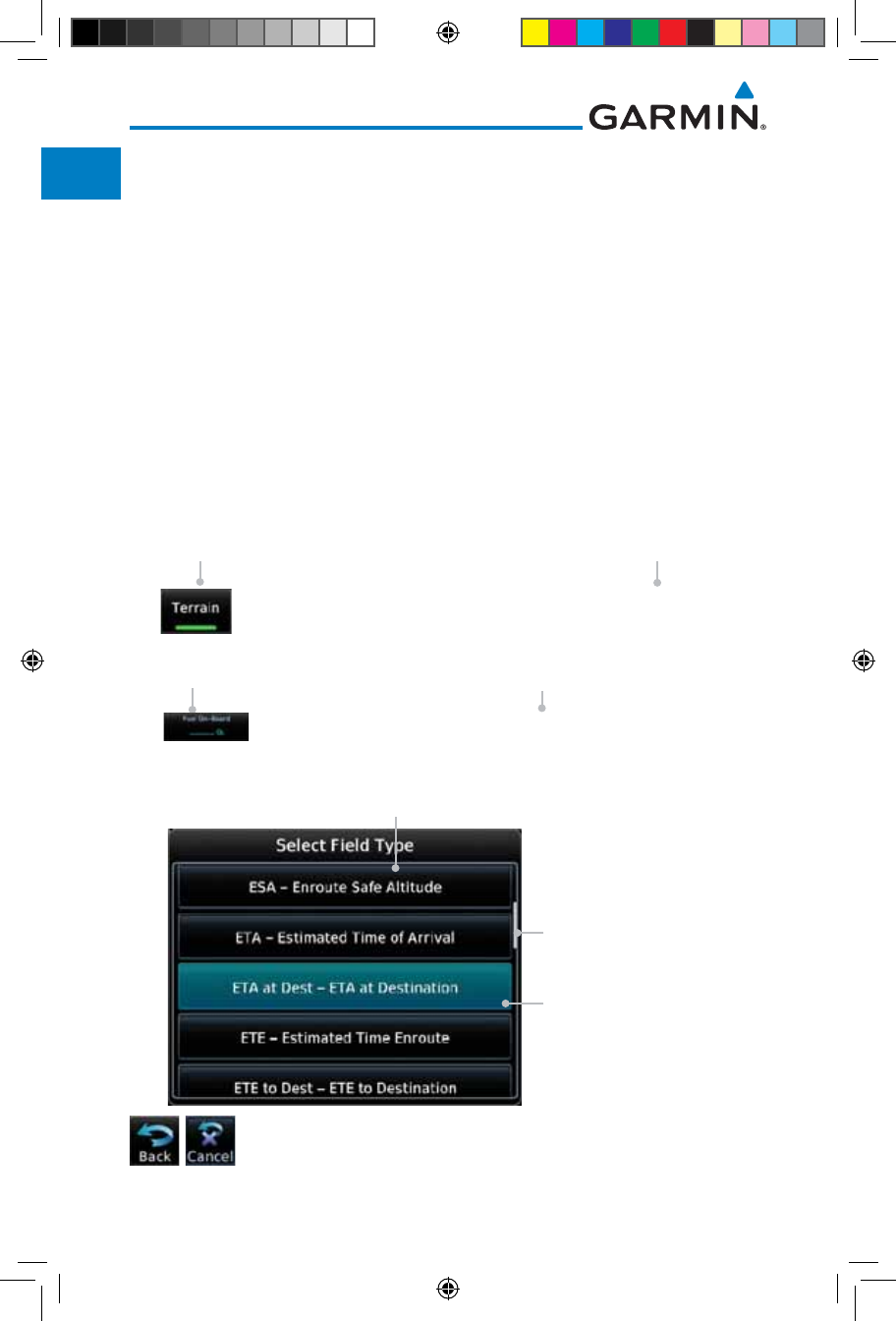
xxviii
Garmin GTN 725/750 Pilot’s Guide
190-01007-03 Rev. J
Foreword
Getting
Started
Audio &
Xpdr Ctrl
Com/Nav
FPL
Direct-To
Proc
Charts
Wpt Info
Map
Traffic
Terrain
Weather
Nearest
Services/
Music
Utilities
System
Messages
Symbols
Appendix
Index
Conventions
The GTN display dynamically tailors the number and position of the controls
for each function and are engaged by merely touching them.
Touch Touch the key with your finger.
Drag Touch the list or location on the map with your finger. Continue
lightly holding your finger to the display surface and drag your
finger in the intended direction to scroll through the list or
move the location on the map.
In this pilot’s guide, keys are noted by bold text. An image of the key used
will be shown to the left of a procedure. Keys are outlined areas on the display.
Figures in the guide will identify the available controls. A key may have a name
of a control, such as Enter, Terrain, or Back. A key may also be an information
field, such as a numeric value that can be changed.
While viewing the Map Menu, touch the Terrain Map
Overlay key to toggle the view of Terrain data.
Graphic Of Key Text Description
Of Key Operation
Graphic Of Key With
Numeric Value
When the Fuel on Board value is selected, touch the Fuel
on Board key to display the Fuel on Board values.
Text Description
Of Key
List “Keys.” Touch To
Select.
Selected Field Type
Scroll Bar Indicates More
Selections Available.
Touch Finger To An Item
In The List And Drag Your
Finger To View More
Selections.
Touching the Back key returns to the previous display. The
Cancel key cancels any information selected or entered and
returns to the previous display.
190-01007-03-Final.indb 28 7/9/2015 2:06:46 PM

1-1190-01007-03 Rev. J
Garmin GTN 725/750 Pilot’s Guide
Foreword
Getting
Started
Audio &
Xpdr Ctrl
Com/Nav
FPL
Direct-To
Proc
Charts
Wpt Info
Map
Traffic
Terrain
Weather
Nearest
Services/
Music
Utilities
System
Messages
Symbols
Appendix
Index
1 GETTING STARTED
1.1 Model Descriptions
This guide covers the operation of the GTN 725 and 750. In general, all
models will be referred to as the GTN 7XX, except where there are physical or
operational differences. The GTN units are 6.25 inches wide and 6 inches high.
The display is a 708 by 600 pixel, 6.9 inch diagonal color LCD with touchscreen
controls. The units include one removable SD data card for the databases and
software upgrades.
The GTN 7XX simplifies your workload with an easy-to-use touch panel that
provides a visual display of both controls and functions. The required controls
are displayed for the selected function. Keys on the display allow you to access
and control their functions by a simple touch on the interactive display.
The GTN 7XX can integrate a variety of avionics that will not only simplify
operation, but also save panel space. The GTN 725 and 750 have their own
GPS/SBAS navigator and flight planning functions. The GTN 750 adds VHF
Com and VHF Nav radios. Selected optional external equipment allows you
to display and control active traffic systems, XM Entertainment Radio, XM
Weather, audio panel, and a Mode S transponder directly from the GTN 7XX
display, and more. When the optional audio panel and/or transponder are not
installed, the area on the upper portion of the display is used for configurable
navigation information.
1.1.1 GTN 725
The GTN 725 has a GPS/SBAS engine and is TSO C146c certified for
primary domestic, oceanic, and remote navigation including en route, terminal,
and non-precision approaches, and approaches with vertical guidance, such
as LPV and LNAV/VNAV. The GTN 725 can simultaneously give aviators vital
approach information and weather and traffic data in relation to their position
on a large, color moving map display. Thanks to a high-contrast color display,
the information can be easily read from wide viewing angles even in direct
sunlight. Its color moving map features a built-in database that shows cities,
highways, railroads, rivers, lakes, coastlines, and a complete Jeppesen database.
The Jeppesen database (that can be updated with a front-loading data card)
contains all airports, VORs, NDBs, Intersections, FSSs, Approaches, DPs/STARs,
and SUA information.
190-01007-03-Final.indb 1 7/9/2015 2:06:47 PM
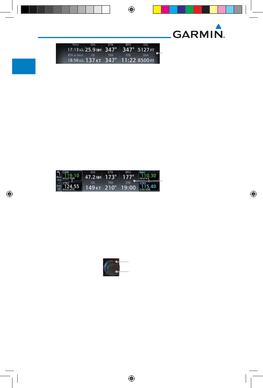
1-2
Garmin GTN 725/750 Pilot’s Guide
190-01007-03 Rev. J
Foreword
Getting
Started
Audio &
Xpdr Ctrl
Com/Nav
FPL
Direct-To
Proc
Charts
Wpt Info
Map
Traffic
Terrain
Weather
Nearest
Services/
Music
Utilities
System
Messages
Symbols
Appendix
Index
Navigation Information
Figure 1-1 GTN 725 Upper Display Without Optional Transponder or Audio Panel
Pilots will enjoy the GTN 725 as a flexible and powerful navigator, especially
when it is coupled with traffic, lightning detection, and weather interfaces. With
the PC-based FDE prediction program, the GTN 725 may be used for oceanic
or remote operations. For the latest in graphic and text weather information,
the GTN 725 can interface to XM Satellite Radio’s XM Weather Service via the
Garmin GDL 69/69A datalink receiver.
1.1.2 GTN 750
The GTN 750 includes all of the features of the GTN 725, and also includes
a TSO’d airborne VHF communications transceiver and TSO’d airborne VOR/
Localizer and Glideslope receivers.
Navigation Information
Figure 1-2 GTN 750 Upper Display Without Optional Transponder or Audio Panel
1.2 About This Pilot’s Guide
1.2.1 Conventions
Bold text indicates a control. The small right knob is the smaller, inner knob
of the two concentric rotary knobs on the lower, right corner of the bezel. The
large right
knob is the larger, outer knob.
Small, Inner Knob
Large, Outer Knob
Figure 1-3 Large/Small Concentric Knobs
A graphic of a control on the side of the page refers to the control you should
use for the associated step as shown below.
1.2.2 Using the Touchscreen
Most of the controls are operated by touching the display. Highlighted icons
and keys may be simply touched to make a selection. A list of menu items may
be scrolled by touching the screen and retaining pressure while sliding your
190-01007-03-Final.indb 2 7/9/2015 2:06:47 PM
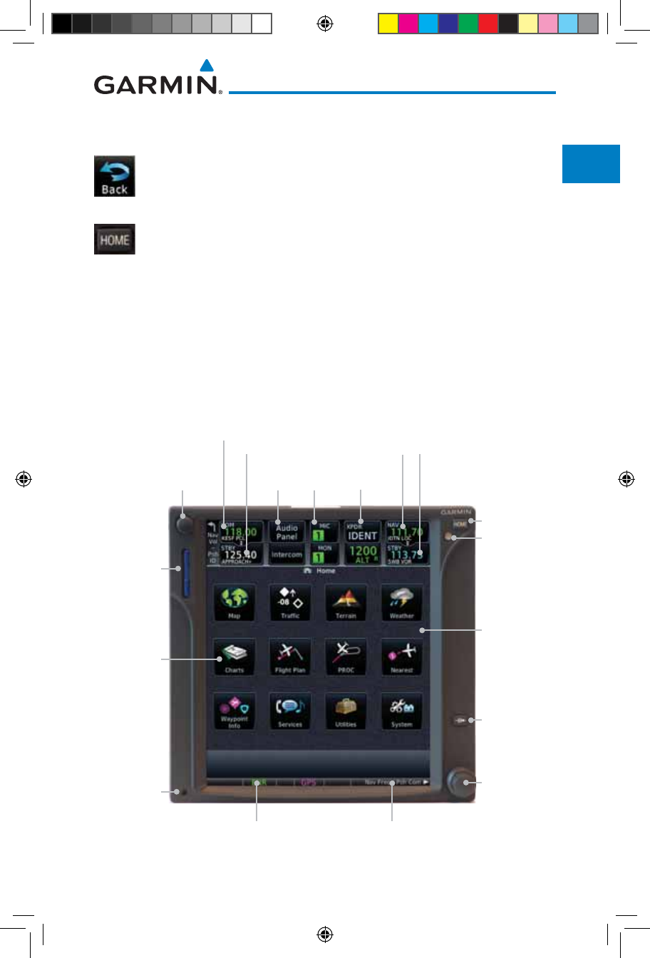
1-3190-01007-03 Rev. J
Garmin GTN 725/750 Pilot’s Guide
Foreword
Getting
Started
Audio &
Xpdr Ctrl
Com/Nav
FPL
Direct-To
Proc
Charts
Wpt Info
Map
Traffic
Terrain
Weather
Nearest
Services/
Music
Utilities
System
Messages
Symbols
Appendix
Index
finger up or down. Map displays may be panned by touching the screen and
retaining pressure while sliding your finger in the desired direction.
You can return to the previous page or exit the current function
by touching the Back key.
Quickly return to the Home page by pressing the HOME key.
Press and hold the HOME key to reach the Map page.
1.3 Product Description
This section provides an overview of the GTN 7XX product and a quick look
at some important features. The GTN 7XX presents a full-color moving map
with navigation information to the pilot through a large-format display. Controls
are a combination of rotary knobs and push-keys on the bezel with the color
display providing information as well as a touchscreen controls. The GTN 7XX
has a 708 x 600 pixel, 6.9 inch LCD display.
Large and
Small Knobs
Volume, Squelch On/
Off, and Nav ID On/Off
Active Com Frequency Standby Com
Frequency
Active Nav
Frequency
Standby Nav
Frequency
Direct-To Key
Photo Sensor
HOME Key
SD Card
Home Page
Annunciations
Function
Keys
Dual Rotary Knob Function Hints
Locking
Screw
Audio Panel
Controls (opt)
Xpdr Panel
Controls (opt)
Figure 1-4 GTN 750 Front Panel
190-01007-03-Final.indb 3 7/9/2015 2:06:48 PM
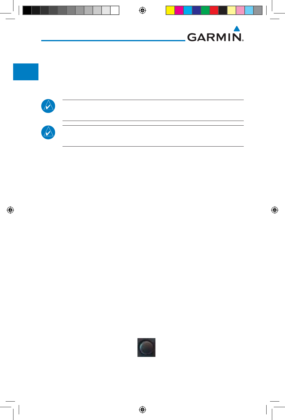
1-4
Garmin GTN 725/750 Pilot’s Guide
190-01007-03 Rev. J
Foreword
Getting
Started
Audio &
Xpdr Ctrl
Com/Nav
FPL
Direct-To
Proc
Charts
Wpt Info
Map
Traffic
Terrain
Weather
Nearest
Services/
Music
Utilities
System
Messages
Symbols
Appendix
Index
1.3.1 Secure Data Card
The GTN 7XX uses a Secure Digital (SD) card to load and store various
types of data. For basic flight operations, the SD card is required for Terrain,
FliteChart, and ChartView database storage. An SD card is used for Obstacle,
Basemap, SafeTaxi, Aviation, and ChartView database updates.
NOTE: Do Not remove or insert the SD card while in flight. Ensure the
GTN 7XX is powered off before inserting or removing an SD card.
NOTE: Refer to SD Card Use and Databases in the Appendix for instructions
on updating databases.
1.3.1.1 Inserting an SD Card
1. Insert the SD card in the SD card slot (the label side of the card
should face the right edge of the display bezel).
2. To eject the card, gently press on the SD card to release the
spring latch.
1.3.2 Pilot Controls
The GTN 7XX controls have been designed to simplify operation of the
system and minimize workload and the time required to access sophisticated
functionality. Controls are located on the bezel and on the touchscreen display.
Controls are comprised of dual concentric knobs, volume/squelch knob, bezel
keys, and active touch areas on the display.
1.3.2.1 Volume/Squelch Knob
The Volume knob located in the top left corner of the bezel controls
audio
volume for the selected Com radio or Nav receiver and external audio input
devices that are controlled via the GTN interface to the optional remote-mounted
audio panel, if installed. When the Com radio is active,
press the Volume knob
momentarily to disable automatic squelch control for the Com radio.
When the
Nav radio is active, press
the Volume knob
momentarily to enable/disable the
ident tone for the Nav radio
.
Figure 1-5 Volume/Squelch Knob
190-01007-03-Final.indb 4 7/9/2015 2:06:48 PM
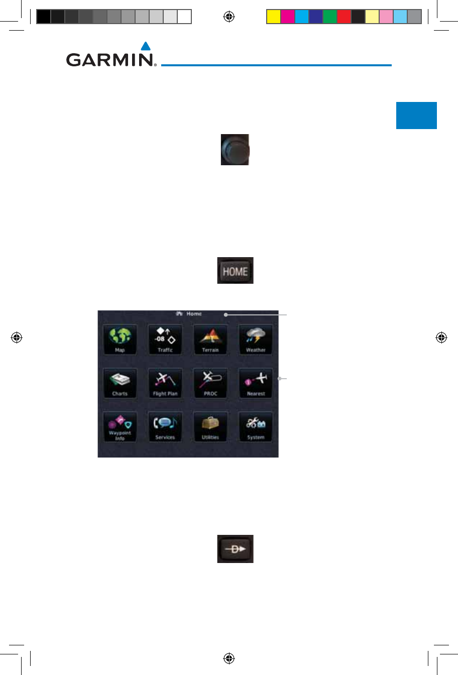
1-5190-01007-03 Rev. J
Garmin GTN 725/750 Pilot’s Guide
Foreword
Getting
Started
Audio &
Xpdr Ctrl
Com/Nav
FPL
Direct-To
Proc
Charts
Wpt Info
Map
Traffic
Terrain
Weather
Nearest
Services/
Music
Utilities
System
Messages
Symbols
Appendix
Index
1.3.2.2 Large/Small Concentric Knobs
The large right and
small right
knobs are used for data entry, such as in the
Waypoint or Direct-To functions, and to set the frequencies for the NAV/COM
radios in units so equipped.
Figure 1-6 Large/Small Concentric Knobs
1.3.2.3 HOME Key
Pressing the HOME key displays the Home page, the main screen for
accessing the GTN features. Pressing and holding the HOME key will open the
Map page from any other page.
Figure 1-7 HOME Key
Touch The Key To
Access The Function
Page Or Function Name
Figure 1-8 Home Page
1.3.2.4 Direct-To Key
The Direct-To key provides access to the direct-to function, which allows you
to enter a waypoint and establishes a direct course to the selected destination.
Figure 1-9 Direct-To Key
190-01007-03-Final.indb 5 7/9/2015 2:06:48 PM
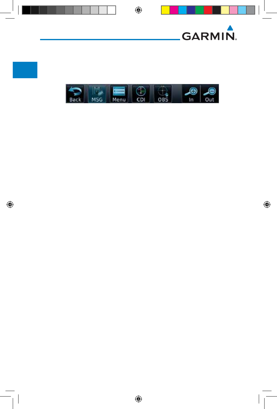
1-6
Garmin GTN 725/750 Pilot’s Guide
190-01007-03 Rev. J
Foreword
Getting
Started
Audio &
Xpdr Ctrl
Com/Nav
FPL
Direct-To
Proc
Charts
Wpt Info
Map
Traffic
Terrain
Weather
Nearest
Services/
Music
Utilities
System
Messages
Symbols
Appendix
Index
1.3.2.5 Touchscreen Keys
Touchscreen keys are placed at the lower portion of the display. The keys vary
depending on the page selected. Touch the key to perform the function or access
the described information.
Figure 1-10 Touchscreen Key Control Example
1.4 Unit Power Up
The GTN 7XX System is integrated with the aircraft electrical system and
receives power directly from electrical busses. The GTN 7XX and supporting
sub-systems include both power-on and continuous built-in test features that
exercise the processor, memory, external inputs, and outputs to ensure safe
operation.
1.4.1 Start-Up Screens
During system initialization, test annunciations are displayed. All system
annunciations should disappear typically within the first 30 seconds after
power-up. Upon power-up, key annunciator lights also become momentarily
illuminated on the GTN 7XX display bezel.
The splash screen displays the following information:
• Copyright
• Database List and System version
• Instrument Panel Self-Test
Current database information includes valid operating dates, cycle number,
and database type. When this information has been reviewed for currency (to
ensure that no databases have expired), the pilot is prompted to continue.
Databases that are not current will be shown in amber.
During the startup process the user may be asked if they would like to update
to newer databases. Additional information on database updates can be found in
section 16.1.3.1, Database Info.
190-01007-03-Final.indb 6 7/9/2015 2:06:48 PM
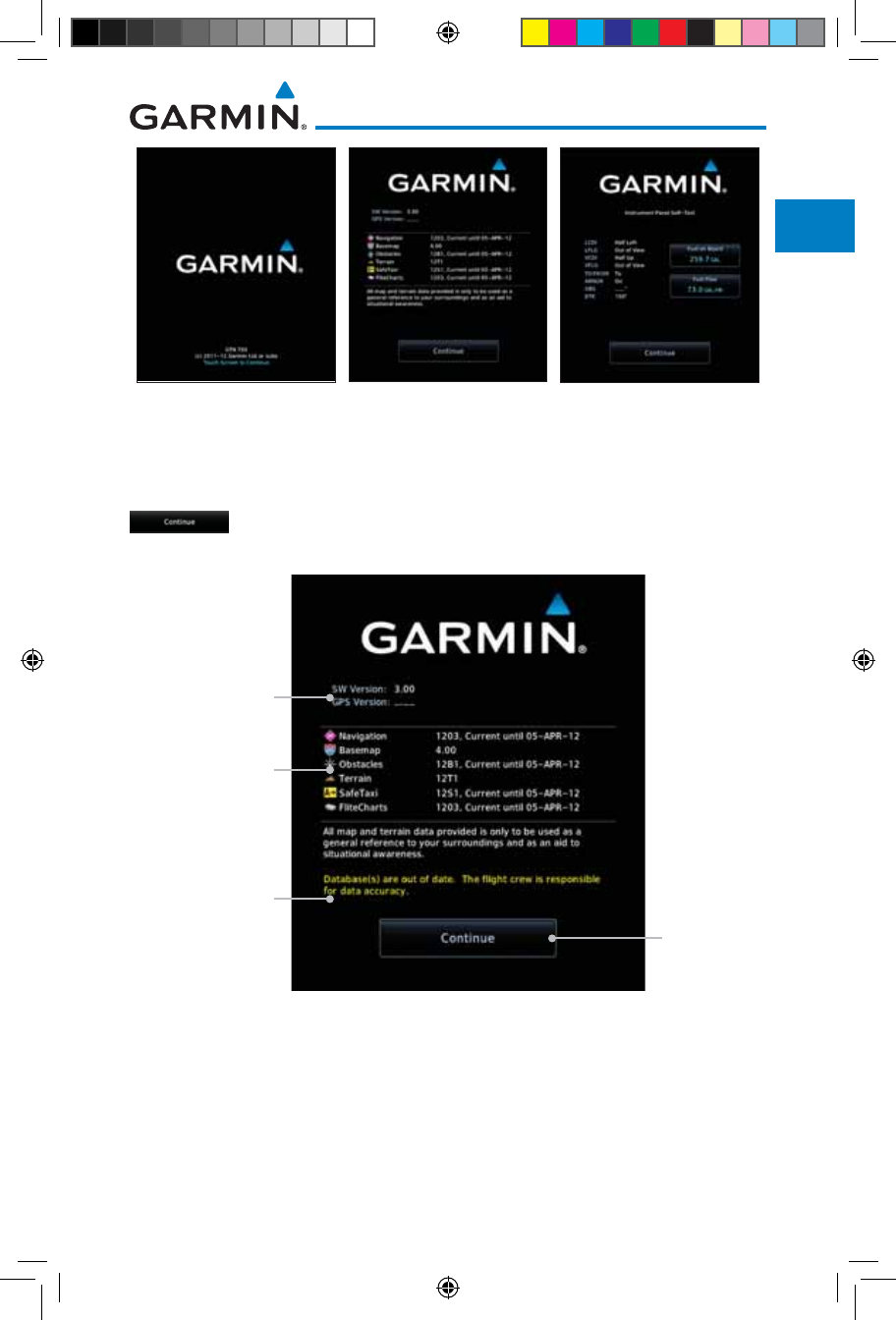
1-7190-01007-03 Rev. J
Garmin GTN 725/750 Pilot’s Guide
Foreword
Getting
Started
Audio &
Xpdr Ctrl
Com/Nav
FPL
Direct-To
Proc
Charts
Wpt Info
Map
Traffic
Terrain
Weather
Nearest
Services/
Music
Utilities
System
Messages
Symbols
Appendix
Index
1 - Copyright 2 - SW & Database
Versions & Dates 3 - Panel Self-Test
Figure 1-11 System Startup Pages
1.4.2 Database Verification and Fuel Settings
1. When the System and Database Version page appears, check
to ensure databases are current. Then, touch Continue.
Check To Ensure
Required Databases
Are Present And
Current
Touch To
Continue To
Home Page
Software and GPS
Engine Versions
Check For Any
Messages
Figure 1-12 System Startup Pages
2. When the Instrument Panel Self-Test and Fuel Setting page
appears, check to ensure that the CDI/HSI outputs and
other displayed data are correct on the external interfaced
equipment.
190-01007-03-Final.indb 7 7/9/2015 2:06:49 PM
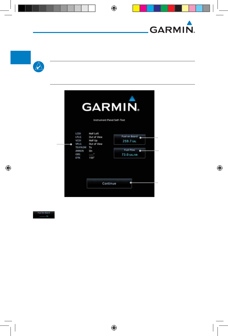
1-8
Garmin GTN 725/750 Pilot’s Guide
190-01007-03 Rev. J
Foreword
Getting
Started
Audio &
Xpdr Ctrl
Com/Nav
FPL
Direct-To
Proc
Charts
Wpt Info
Map
Traffic
Terrain
Weather
Nearest
Services/
Music
Utilities
System
Messages
Symbols
Appendix
Index
3. Touch each of the Fuel value keys and set the appropriate
values as desired. Fuel capacity is shown in either gallons or
pounds as set in the Units feature of System mode.
NOTE: When the GTN is interfaced with a digital fuel computer the pilot
may not be able to manually edit the fuel flow and fuel on board data on
the Self-Test.
Touch To Set
Current Fuel
Quantity
Start-Up
Instrument
Panel Test
Conditions
Touch To Continue
To Home Page
Touch To Set
Fuel Flow
Figure 1-13 Instrument Panel Self-Test & Fuel Settings Page
4. When the Fuel on Board value is selected, touch the Fuel on
Board key to display the Fuel on Board values. Touch the Full
or Tabs keys to display those values after they have been set.
190-01007-03-Final.indb 8 7/9/2015 2:06:49 PM
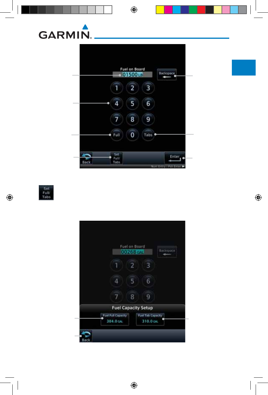
1-9190-01007-03 Rev. J
Garmin GTN 725/750 Pilot’s Guide
Foreword
Getting
Started
Audio &
Xpdr Ctrl
Com/Nav
FPL
Direct-To
Proc
Charts
Wpt Info
Map
Traffic
Terrain
Weather
Nearest
Services/
Music
Utilities
System
Messages
Symbols
Appendix
Index
Touch To
Delete
Characters
Touch To
Display Fuel
Full Capacity
Touch To Set
Fuel Full or Tab
Capacity
Touch To
Accept Fuel on
Board Values
Touch To
Display Fuel
Tabs Capacity
Selected Fuel
on Board
Capacity
Touch Keys
To Select Fuel
Capacity Values
Figure 1-14 Fuel On Board Page
5. Touch the Set Full/Tabs key to set the fuel values for Fuel
Full Capacity and Fuel Tab Capacity. After setting the fuel
values, touch the Back and then the Enter keys to return to
the Instrument Panel Self Test page.
Touch To
Set Fuel Tab
Capacity
Touch To
Set Fuel Full
Capacity
Touch To Return
To Fuel On
Board Display
Figure 1-15 Fuel Capacity Setup Page
190-01007-03-Final.indb 9 7/9/2015 2:06:49 PM
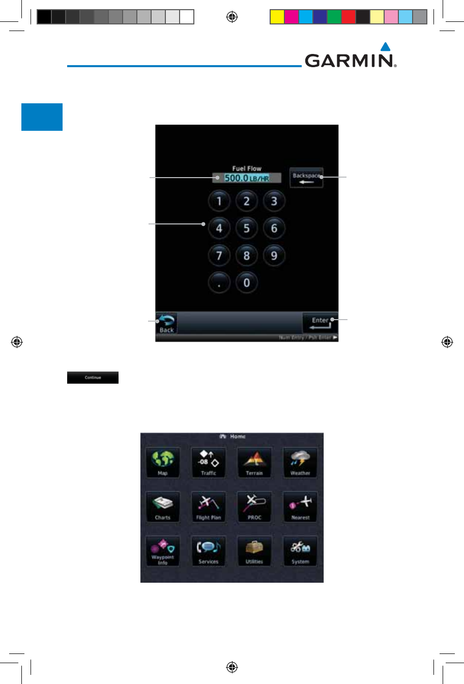
1-10
Garmin GTN 725/750 Pilot’s Guide
190-01007-03 Rev. J
Foreword
Getting
Started
Audio &
Xpdr Ctrl
Com/Nav
FPL
Direct-To
Proc
Charts
Wpt Info
Map
Traffic
Terrain
Weather
Nearest
Services/
Music
Utilities
System
Messages
Symbols
Appendix
Index
6. On
the Instrument Panel Self Test page
, touch the Fuel Flow
key and then use the numeric keypad to set those values. Touch
the Enter key after selecting the Fuel Flow values.
Touch To
Delete
Characters
Touch To
Accept Fuel
Flow Values
Selected Fuel
Flow Value
Touch Keys To Select
Fuel Flow Values
Touch To Cancel
Selection And Return
To Previous Page
Figure 1-16 Fuel Flow Setup Page
7. Touch the Back key to return to the Fuel on Board page.
Touch the Enter key to accept the fuel values and return to
the Instrument Panel Self-Test page. Then, touch the Continue
key to advance to the Home page.
Figure 1-17 Home Page
190-01007-03-Final.indb 10 7/9/2015 2:06:49 PM
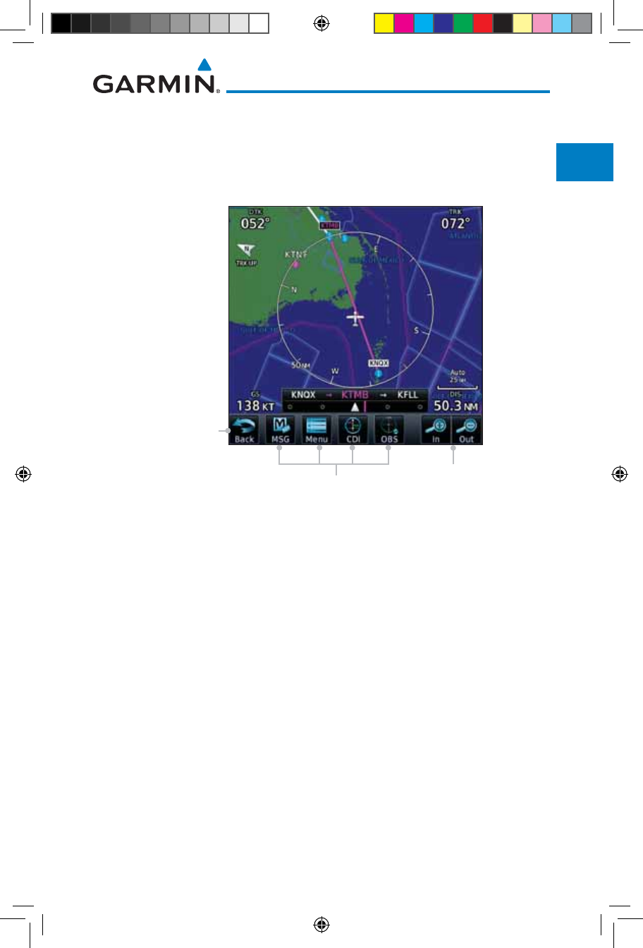
1-11190-01007-03 Rev. J
Garmin GTN 725/750 Pilot’s Guide
Foreword
Getting
Started
Audio &
Xpdr Ctrl
Com/Nav
FPL
Direct-To
Proc
Charts
Wpt Info
Map
Traffic
Terrain
Weather
Nearest
Services/
Music
Utilities
System
Messages
Symbols
Appendix
Index
1.5 System Operation
1.5.1 Using the Touchscreen Key Controls
Except for the knobs, the HOME, and Direct-To keys on the bezel, the
controls for the GTN 7XX are located on the display and activated by touch.
Back to
Previous Page
Touchscreen Keys - Touch to
Toggle Activation
Touch to Zoom
In and Out
Figure 1-18 On-Screen Keys and Active Display Areas
1.5.2 System Page
GTN 7XX system settings are managed on the System page. The
following features are available:
• System Status
• GPS Status
• External LRUs
• Setup
• Alerts Settings
• User Fields
• Units Settings
• Audio
• Backlight
• Connext Setup
• Voice Commands
190-01007-03-Final.indb 11 7/9/2015 2:06:49 PM
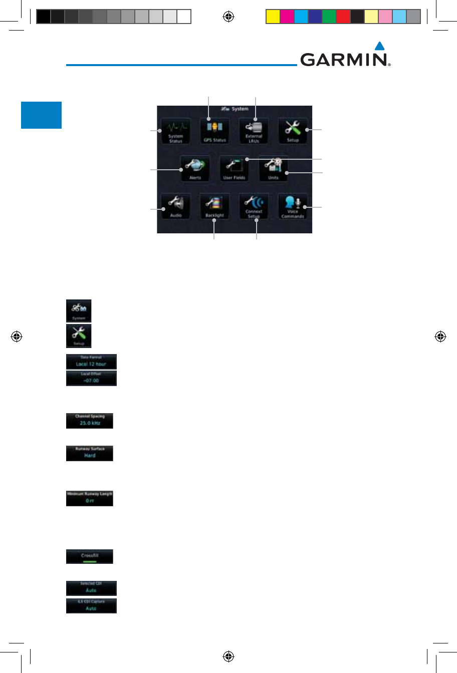
1-12
Garmin GTN 725/750 Pilot’s Guide
190-01007-03 Rev. J
Foreword
Getting
Started
Audio &
Xpdr Ctrl
Com/Nav
FPL
Direct-To
Proc
Charts
Wpt Info
Map
Traffic
Terrain
Weather
Nearest
Services/
Music
Utilities
System
Messages
Symbols
Appendix
Index
Set System Units
Of Measurement
Set Alert Values
Select Audio Settings Select Voice
Command Setup
View System
Status Values
and SW Versions
GPS Status Page &
SBAS Providers
Information on
External LRUs
Select System
Setup Values
Select Backlight
Setting
Select Connext Setup
Select User Fields
Figure 1-19 System Page
1.5.2.1 System Setup Values
1. From the Home page, touch System and then Setup.
2. Select the desired Time Format and Local Offset by touching
the Time Format (12 Hour, 24 Hour, and/or UTC) keys and
selecting the appropriate Local Time Offset after touching the
Local Offset key.
3. Touch the Com Channel Spacing key to toggle between
8.33 and 25.0 kHz channel spacing.
4. For Nearest Airport filtering, touch the Runway Surface key
and select the desired type of surface that will appear in the
Nearest Airport list.
5. Touch the Minimum Runway Length key to select the
minimum runway length allowed for the Nearest Airport.
Selecting 0 feet will show all airports regardless of runway
length.
6. Touch the Crossfill key to enable or disable crossfill with a
second GTN unit.
7. Select the CDI and ILS CDI Capture method with the Selected
CDI and ILS CDI Capture keys.
190-01007-03-Final.indb 12 7/9/2015 2:06:50 PM
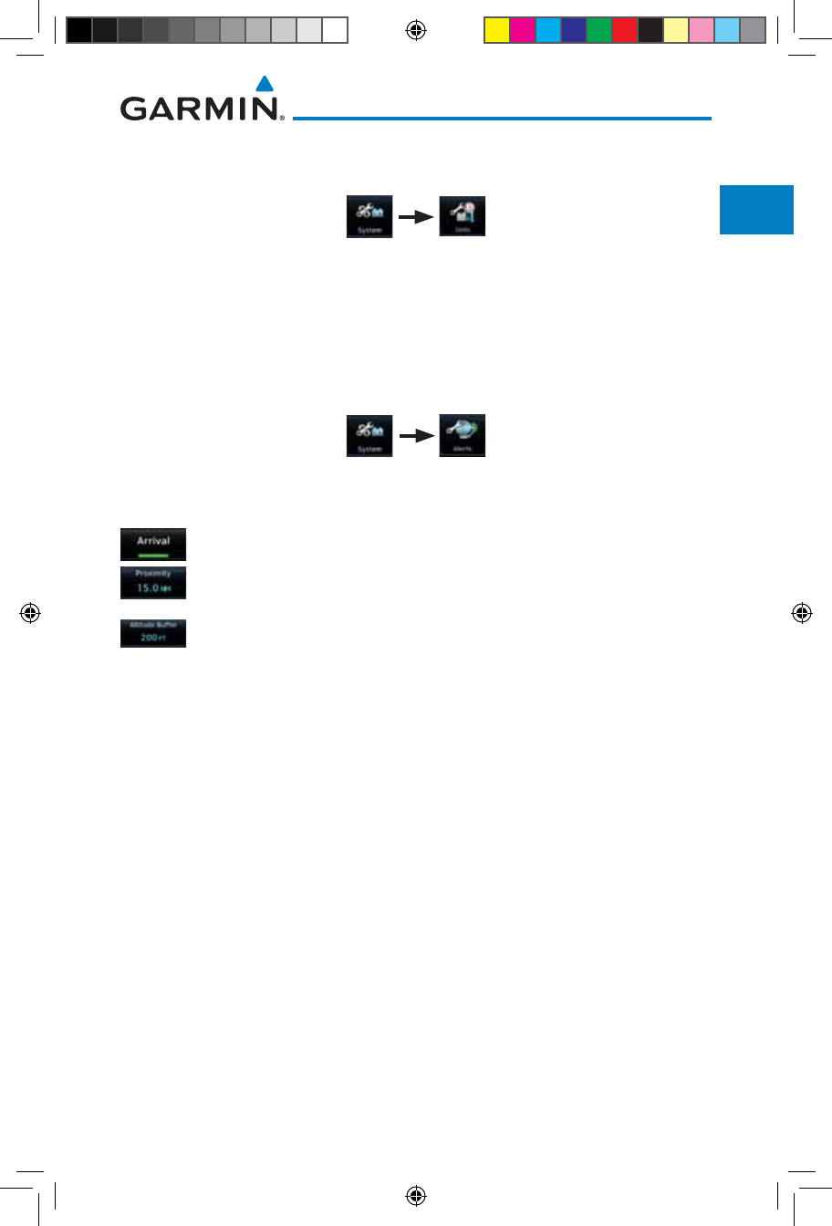
1-13190-01007-03 Rev. J
Garmin GTN 725/750 Pilot’s Guide
Foreword
Getting
Started
Audio &
Xpdr Ctrl
Com/Nav
FPL
Direct-To
Proc
Charts
Wpt Info
Map
Traffic
Terrain
Weather
Nearest
Services/
Music
Utilities
System
Messages
Symbols
Appendix
Index
1.5.2.2 Units Settings Values
1. From the Home page, touch System and then Units.
2. Touch the desired item key and select the desired value.
3. Continue to select the desired Units values and then touch the
Back or HOME key to exit.
1.5.2.3 Alerts Settings Values
1. From the Home page, touch System and then Alerts.
2. Touch the Alert type key to toggle its active status. A lighted
green bar under the label indicates that it is active.
3. Set arrival alerting. Touch the Arrival key. Touch the Proximity
key and select the desired value with the keypad.
4. Touch the Airspace Altitude Buffer key and select the
desired value for airspace alerting.
5. Continue to select the desired Alerts values and then touch
the Back or HOME key to exit.
1.5.2.4 Audio Values
1. From the Home page, touch System and then Audio.
2. Touch the arrow keys to raise or lower the volume of key click
sounds.
1.5.2.5 Backlight Values
1. From the Home page, touch System and then Backlight.
2. Touch the arrow keys to increase or decrease the Manual
Offset of the backlight brightness.
190-01007-03-Final.indb 13 7/9/2015 2:06:50 PM

1-14
Garmin GTN 725/750 Pilot’s Guide
190-01007-03 Rev. J
Foreword
Getting
Started
Audio &
Xpdr Ctrl
Com/Nav
FPL
Direct-To
Proc
Charts
Wpt Info
Map
Traffic
Terrain
Weather
Nearest
Services/
Music
Utilities
System
Messages
Symbols
Appendix
Index
1.5.2.6 Connext Setup
1. From the Home page, touch System and then Connext
Setup.
2. This page is used to setup Connext devices that are connected
to the GTN.
1.5.2.7 Voice Commands
1. From the Home page, touch System and then Voice
Commands.
2. This page is used to turn voice recognition on or off, and to
view voice command history.
190-01007-03-Final.indb 14 7/9/2015 2:06:50 PM
1-15190-01007-03 Rev. J
Garmin GTN 725/750 Pilot’s Guide
Foreword
Getting
Started
Audio &
Xpdr Ctrl
Com/Nav
FPL
Direct-To
Proc
Charts
Wpt Info
Map
Traffic
Terrain
Weather
Nearest
Services/
Music
Utilities
System
Messages
Symbols
Appendix
Index
1.5.3 Dual GTN Installations
Dual GTN units when connected in the aircraft may be set up to communicate
and share information by “Crossfilling” or synchronizing information between
the two units.
The following Crossfill information is always synchronized between both
GTN units:
• User Waypoints
• Flight Plan Catalog
• Alerts (traffic pop-up acknowledgement, missed approach waypoint pop-
up acknowledgement, altitude leg pop-up acknowledgement)
• External sensors (transponder status and commands, synchro heading)
• System setup:
– User-defined NAV frequencies to store favorites
– Date/Time convention
– Nearest airport criteria
– Units (Nav angle, Fuel, and Temperature)
– User-defined COM frequencies to store favorites
– CDI Scale setting
– ILS CDI Capture setting
This data is crossfilled only if crossfill is turned on by the pilot:
• Active navigation (flight plan)
NOTE: In dual GTN installations with crossfill on, the OBS course will only
be updated in real time on the GTN that is receiving the new OBS course.
The course will be transferred to the other GTN when OBS is exited.
NOTE: There is an installer option to turn on a system message that will
be provided anytime crossfill is turned off to alert the pilot that flight plans
are not being crossfilled.
190-01007-03-Final.indb 15 7/9/2015 2:06:50 PM
1-16
Garmin GTN 725/750 Pilot’s Guide
190-01007-03 Rev. J
Foreword
Getting
Started
Audio &
Xpdr Ctrl
Com/Nav
FPL
Direct-To
Proc
Charts
Wpt Info
Map
Traffic
Terrain
Weather
Nearest
Services/
Music
Utilities
System
Messages
Symbols
Appendix
Index
1.6 Direct-To Navigation
Press the Direct-To key to quickly navigate from your present position
directly to a selected waypoint, flight plan waypoint, or nearest airport.
1.6.1 Direct-To a Waypoint
1. Press Direct-To.
2. Touch the Waypoint Identifier field and select the characters for
the desired waypoint with the large and small right knobs
or the touch keypad.
OR
3. Touch Activate or press the small right knob. Text near the
small right knob indicates its current function.
1.6.2 Direct-To a Flight Plan Waypoint
1. Press Direct-To.
2. Touch the FPL tab and then the desired Flight Plan
waypoint.
OR
3. Touch Activate or press the small right knob.
1.6.3 Direct-To a Nearest Airport
1. Press Direct-To.
2. Touch the NRST APT tab and then the desired airport from
the Nearest Airport list. Touch the Up or Down keys as needed
to show more of the list.
OR
3. Touch Activate or press the small right knob.
190-01007-03-Final.indb 16 7/9/2015 2:06:51 PM
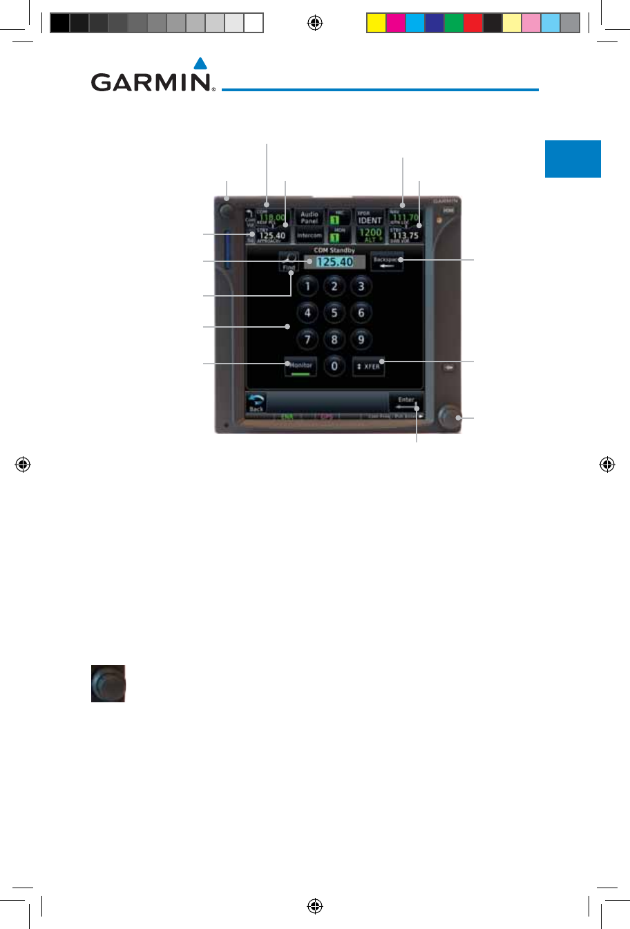
1-17190-01007-03 Rev. J
Garmin GTN 725/750 Pilot’s Guide
Foreword
Getting
Started
Audio &
Xpdr Ctrl
Com/Nav
FPL
Direct-To
Proc
Charts
Wpt Info
Map
Traffic
Terrain
Weather
Nearest
Services/
Music
Utilities
System
Messages
Symbols
Appendix
Index
1.7 Selecting Com/Nav Frequencies
Large and
Small Knobs
(Frequency
Adjust)
Volume and
Squelch
Active Com Frequency
Standby Com
Frequency
Active Nav Frequency
Standby Nav Frequency
Com Standby
Editing Window
Frequency Monitor
Annunciation
Standby
Frequency
Backspace
Key
Standby Frequency
Monitor Key
Frequency
Transfer
(Flip/Flop)
Key
Find Frequency
Key
Enter Key
Numeric Keypad
Figure 1-20 Com Radio Frequency Selection Page
To switch between Com and Nav frequency selection
Tuning control normally remains in the Com window and will return after 30
seconds of inactivity. If you wish to select a Nav frequency, press the small right
knob momentarily to make the Nav window active for editing. The Standby
Nav frequency will be highlighted briefly to indicate that it is active for editing.
The standby frequency in blue is active for editing by the large and small right
knobs.
Method 1: Select a Nav/Com frequency using the small and large right rotary knobs
1. Turn the large right knob to select the desired megahertz
(MHz) value. For example, the “118” portion of the frequency
“118.30”.
2. Turn the small right knob to select the desired kilohertz
(kHz) value. For example, the “.30” portion of the frequency
“118.30”.
3. Touch the Com or Nav window to flip/flop the Active and Standby
frequencies. You can also press and hold the small right knob
to transfer the standby frequency to the active window.
190-01007-03-Final.indb 17 7/9/2015 2:06:51 PM
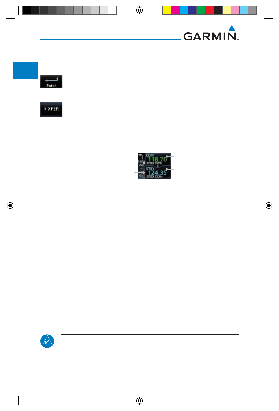
1-18
Garmin GTN 725/750 Pilot’s Guide
190-01007-03 Rev. J
Foreword
Getting
Started
Audio &
Xpdr Ctrl
Com/Nav
FPL
Direct-To
Proc
Charts
Wpt Info
Map
Traffic
Terrain
Weather
Nearest
Services/
Music
Utilities
System
Messages
Symbols
Appendix
Index
Method 2: Select a Nav/Com frequency using the numeric keypad
1. Touch the Standby window. A pull down keypad will appear
with the current Standby frequency highlighted.
2. Touch the numeric keys to add the desired values and touch
Enter to accept the displayed value and place it into the
Standby window.
3. Touching the XFER key will place the selected frequency directly
into the Active window.
To transfer the standby frequency to the active frequency
1. Touch the Active (top) frequency window.
The "+" Sign Indicates More Stations
Associated With This Frequency
Airport Identifier and Type Shown
for the Selected Frequency
Active Com Frequency
(Touch to Flip/Flop)
Standby Com Frequency
Figure 1-21 Com Radio Frequency Windows (Touch Active to Flip/Flop)
2. Each touch of the Active window will flip/flop the Active and
Standby frequencies.
3. The identifier and frequency type will be shown for the selected
Com and Nav frequencies for the nearest stations that are in
the database when the unit is receiving a valid position input.
Remote Frequency Selection Control
On units configured for remote Com frequency Recall, pressing the remote
recall switch will load the next preset Com frequency into the unit’s Standby
frequency window. The remote recall switch can be pressed multiple times to
scroll the entire preset frequency list through the Standby frequency box (the list
will “wrap” from the bottom of the list back up to the top, skipping any empty
preset positions).
The standby frequency isn’t activated until a Com FLIP/FLOP switch (either
bezel-mounted or remote (COM RMT XFR) is pressed. Remote Frequency Selection
only functions on units configured for a remote Com Frequency recall switch.
NOTE: Frequencies must be stored in the User Frequency List prior to
utilizing the remote channel select switch.
190-01007-03-Final.indb 18 7/9/2015 2:06:51 PM
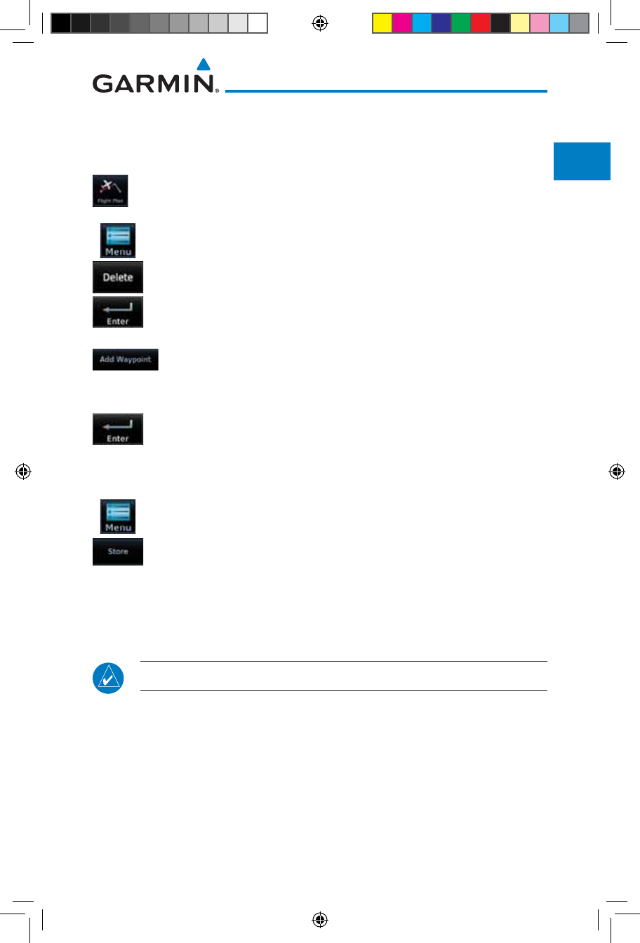
1-19190-01007-03 Rev. J
Garmin GTN 725/750 Pilot’s Guide
Foreword
Getting
Started
Audio &
Xpdr Ctrl
Com/Nav
FPL
Direct-To
Proc
Charts
Wpt Info
Map
Traffic
Terrain
Weather
Nearest
Services/
Music
Utilities
System
Messages
Symbols
Appendix
Index
1.8 Flight Planning
1.8.1 Creating a Flight Plan
1. From the Home page, touch the Flight Plan key. The Active
Flight Plan page will be displayed.
2. If there is already an Active Flight Plan, touch Menu and then
the Delete key to clear the existing flight plan. If there is not
an Active Flight Plan, continue to the next step.
3. Touch Add Waypoint. Use the alphanumeric keypad to select
the Waypoint Identifier for the first leg in your flight plan and
then touch Enter.
4. Touch the next Waypoint Identifier field. Use the alphanumeric
keypad to select the Waypoint Identifier for the first leg in your
flight plan and then touch Enter.
5. Continue entering waypoints to complete the flight plan.
6. Touch the Menu key and then touch Store.
7. The screen will now display the Flight Plan Catalog and show
the new flight plan. Flight plans are listed by the Departure
and Destination waypoints.
NOTE: The destination waypoint is the last airport in the flight plan.
190-01007-03-Final.indb 19 7/9/2015 2:06:51 PM
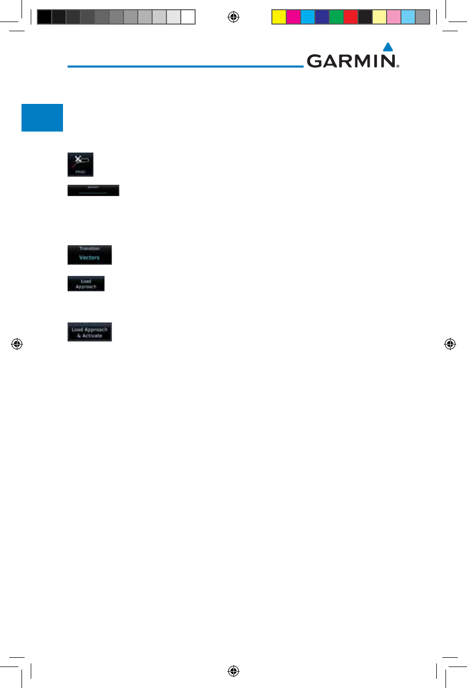
1-20
Garmin GTN 725/750 Pilot’s Guide
190-01007-03 Rev. J
Foreword
Getting
Started
Audio &
Xpdr Ctrl
Com/Nav
FPL
Direct-To
Proc
Charts
Wpt Info
Map
Traffic
Terrain
Weather
Nearest
Services/
Music
Utilities
System
Messages
Symbols
Appendix
Index
1.9 IFR Procedures
Departures (SIDs), arrivals (STARs), non-precision and precision
approaches are available using the PROC (Procedures) key.
Select an Approach
1. Touch the PROC key on the Home page.
2. Touch the Approach key and then touch the Airport key to
select the desired airport if it is not present.
3. Touch the Approach key, if necessary. Select the desired
approach.
4. Touch the Transition key and then touch the key for the
desired transition.
5. Touch the Load Approach key to load the approach at the
end of the active flight plan. The Active Flight Plan page will
be displayed.
6. Or, touch the Load Approach & Activate key for the flight
plan to go Direct-To the selected transition or provide guidance
on the final approach course for vectored approaches.
190-01007-03-Final.indb 20 7/9/2015 2:06:51 PM
1-21190-01007-03 Rev. J
Garmin GTN 725/750 Pilot’s Guide
Foreword
Getting
Started
Audio &
Xpdr Ctrl
Com/Nav
FPL
Direct-To
Proc
Charts
Wpt Info
Map
Traffic
Terrain
Weather
Nearest
Services/
Music
Utilities
System
Messages
Symbols
Appendix
Index
1.10 Dead Reckoning
Dead reckoning is a feature that enables the GTN to provide limited navi-
gation using the last known position and speed after a loss of GPS navigation
while on an active flight plan.
CAUTION: Navigation using dead reckoning is only an estimate and
should not be used as the sole means of navigation. Use other means of
navigation, if possible.
Dead reckoning becomes active after a loss of GPS position while navigating
using an active flight plan and the flight phase is either En Route (ENR) or
Oceanic (OCN).
“DR” will be overlayed on the ownship icon. The To/From flag is removed
from the CDI. The Dead Reckoning annunciator (DR) appears on the lower
left side of the map display and will replace ENR or OCN when a GPS position
is unavailable and the unit is in Dead Reckoning mode. All external outputs
dependent on GPS position are flagged.
Terrain will be noted as not available and new terrain advisory pop-ups will
not occur. Traffic and StormScope information will not be shown on the Map
page, but will continue to be available on their own dedicated pages. XM weather
will still be available on the Map page.
Dead Reckoning mode will continue until GPS position is restored, when GPS
navigation is restored Dead Reckoning mode is exited. The DR annunciations
will be removed and GPS information will be used to compute navigation related
information for the current flight phase.
Dead Reckoning is only allowed in En Route and Oceanic phases of flight.
If the unit is in a Terminal or Approach phase of flight when Dead Reckoning
takes place, “No GPS Position” will be displayed on the map pages and all
navigation data will be dashed. If you are operating in Dead Reckoning mode
and a transition to Terminal or Approach phases of flight would occur from the
projected Dead Reckoning position, Dead Reckoning mode will be discontinued.
“No GPS Position” will be displayed on the map pages and all navigation data
will be dashed.
190-01007-03-Final.indb 21 7/9/2015 2:06:52 PM
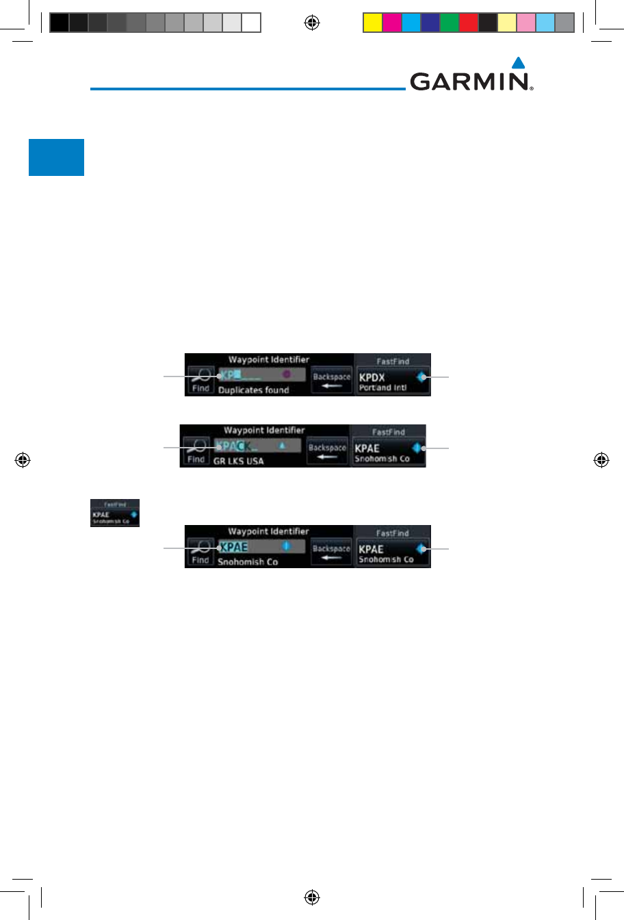
1-22
Garmin GTN 725/750 Pilot’s Guide
190-01007-03 Rev. J
Foreword
Getting
Started
Audio &
Xpdr Ctrl
Com/Nav
FPL
Direct-To
Proc
Charts
Wpt Info
Map
Traffic
Terrain
Weather
Nearest
Services/
Music
Utilities
System
Messages
Symbols
Appendix
Index
1.11 FastFind Predictive Waypoint Entry
FastFind provides the pilot with a shortcut to the nearest waypoint with an
identifier that starts with the typed letters. As a result, the GTN can predict the
pilot's entry within as little as one key press.
FastFind predictions are shown in the top right-hand corner of the keypad
display. Touching the FastFind field will select the predicted waypoint. If the
FastFind prediction is not what the pilot is looking for, keep typing until the
desired waypoint is displayed.
1.11.1 FastFind With
Waypoint Info
1. Use the alphanumeric keypad to begin selecting characters
for the desired waypoint.
Selected Wpt
Characters Predicted Wpt
Figure 1-22 Select Characters for FastFind to Predict a Waypoint - KP Selected
Selected Wpt
Characters Predicted Wpt
Figure 1-23 Select Characters for FastFind to Predict a Waypoint - KPA Selected
2. After selecting the desired waypoint, touch the FastFind key.
Complete
Wpt Selection Touch to Select
Displayed Wpt
Figure 1-24 Select Characters for FastFind to Predict a Waypoint - KPAE Selected
190-01007-03-Final.indb 22 7/9/2015 2:06:52 PM
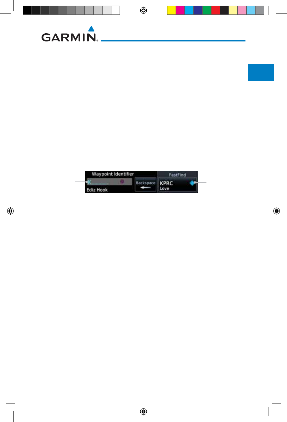
1-23190-01007-03 Rev. J
Garmin GTN 725/750 Pilot’s Guide
Foreword
Getting
Started
Audio &
Xpdr Ctrl
Com/Nav
FPL
Direct-To
Proc
Charts
Wpt Info
Map
Traffic
Terrain
Weather
Nearest
Services/
Music
Utilities
System
Messages
Symbols
Appendix
Index
1.11.2 FastFind With A Flight Plan
When creating a new flight plan or searching for a waypoint, the GTN
will search for waypoints closest to the current GPS position. When adding
waypoints in the middle of the flight plan, the GTN will search halfway between
the previous and next waypoints. When adding waypoints at the end of the
flight plan, the GTN will search for waypoints closest to the last waypoint in the
flightplan.
1. When the aircraft is located in KSLE, and the last waypoint in
the flight plan is "DRK", the GTN will search for waypoints
nearest "DRK".
2. Typing K, will result in "KPRC" being displayed as the FastFind
prediction because it is the nearest waypoint to "DRK" that
starts with "K".
Selected Wpt
Characters Predicted Wpt
Figure 1-25 Using FastFind to Predict a Waypoint in a Flight Plan
190-01007-03-Final.indb 23 7/9/2015 2:06:52 PM

1-24
Garmin GTN 725/750 Pilot’s Guide
190-01007-03 Rev. J
Foreword
Getting
Started
Audio &
Xpdr Ctrl
Com/Nav
FPL
Direct-To
Proc
Charts
Wpt Info
Map
Traffic
Terrain
Weather
Nearest
Services/
Music
Utilities
System
Messages
Symbols
Appendix
Index
This page intentionally left blank
190-01007-03-Final.indb 24 7/9/2015 2:06:52 PM
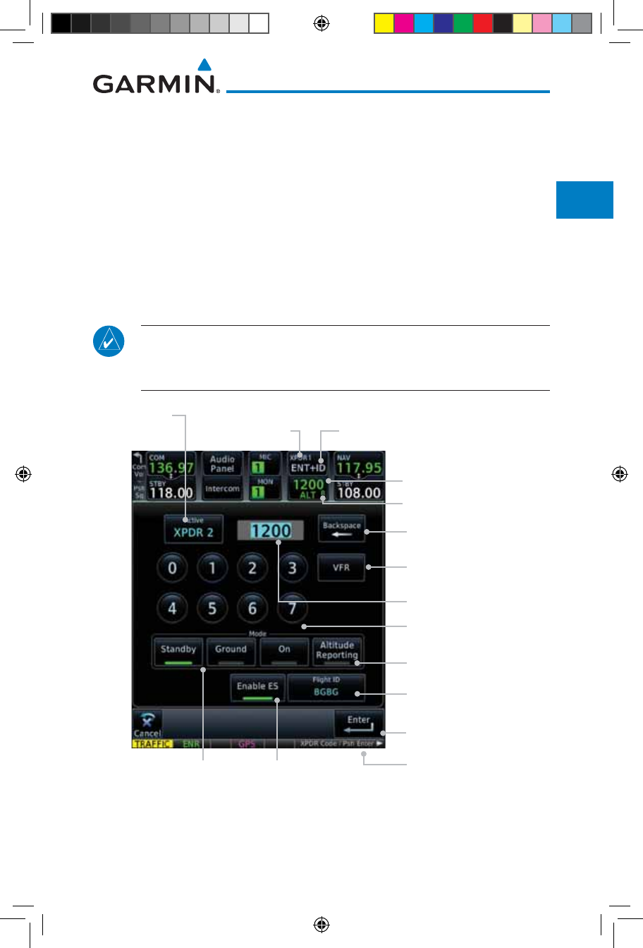
2-1190-01007-03 Rev. J
Garmin GTN 725/750 Pilot’s Guide
Foreword
Getting
Started
Audio &
Xpdr Ctrl
Com/Nav
FPL
Direct-To
Proc
Charts
Wpt Info
Map
Traffic
Terrain
Weather
Nearest
Services/
Music
Utilities
System
Messages
Symbols
Appendix
Index
2 AUDIO AND TRANSPONDER CONTROLS
(OPTIONAL)
The GTN 7XX can perform the control and display for a remotely mounted
audio panel (such as the GMA 35) and a transponder (such as one of the GTX
family of transponders) functions. See your dealer for more information.
2.1 Transponder Operation
The GTN 7XX will operate as a control head for remotely connected optional,
compatible transponders.
NOTE: The transponder control panel on the GTN will not contain the
Ground key when the GTN is interfaced with a GTX 33/330 with software
version 8.00, or later.
Reply Annunciation
VFR Squawk
Code (1200) Key
Squawk Code
Window
Squawk Code
Backspace Key
Enter Key
Numeric Keypad
Context Sensitive
Instructions For Rotary Knob
Transponder Control
Code Key, Code Display,
and Mode
Ident
Key
Active
Transponder
Active
Transponder
Selection
Green Bar Indicates
"Active" Condition
Transponder
Mode Keys
Touch To Enter
Flight ID
Touch To Toggle
Extended Squitter
Figure 2-1 XPDR Control Display
190-01007-03-Final.indb 1 7/9/2015 2:06:52 PM
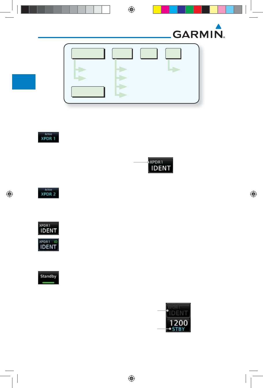
2-2
Garmin GTN 725/750 Pilot’s Guide
190-01007-03 Rev. J
Foreword
Getting
Started
Audio &
Xpdr Ctrl
Com/Nav
FPL
Direct-To
Proc
Charts
Wpt Info
Map
Traffic
Terrain
Weather
Nearest
Services/
Music
Utilities
System
Messages
Symbols
Appendix
Index
Active XPDR
XPDR 1
XPDR 2
Mode
Standby
Ground
On
Altitude Reporting
VFR
1200
Ident
Flight ID
Figure 2-2 XPDR Functional Diagram
2.1.1 Select Transponder
1. Touch the Active XPDR key to activate the desired transponder
by stepping through the available transponders.
Active Transponder
Figure 2-3 Active Transponder Indication
2. The active transponder will be shown on the key.
2.1.2 IDENT
1. Touch the IDENT key once to reply with an identifying squawk
code.
2. The IDENT key will show a green “ID” in the top right corner
of the key to indicate active Ident.
2.1.3 Standby
Touch the Standby key to place the transponder into Standby
mode. The transponder will still be powered, but will not
transmit information. The active transponder indication and
Ident annunciation will be grayed to show they are disabled.
Active XPDR and IDENT Disabled
Transponder Operation "Standby" Mode
Figure 2-4 Transponder Mode "Standby" Indication
190-01007-03-Final.indb 2 7/9/2015 2:06:52 PM
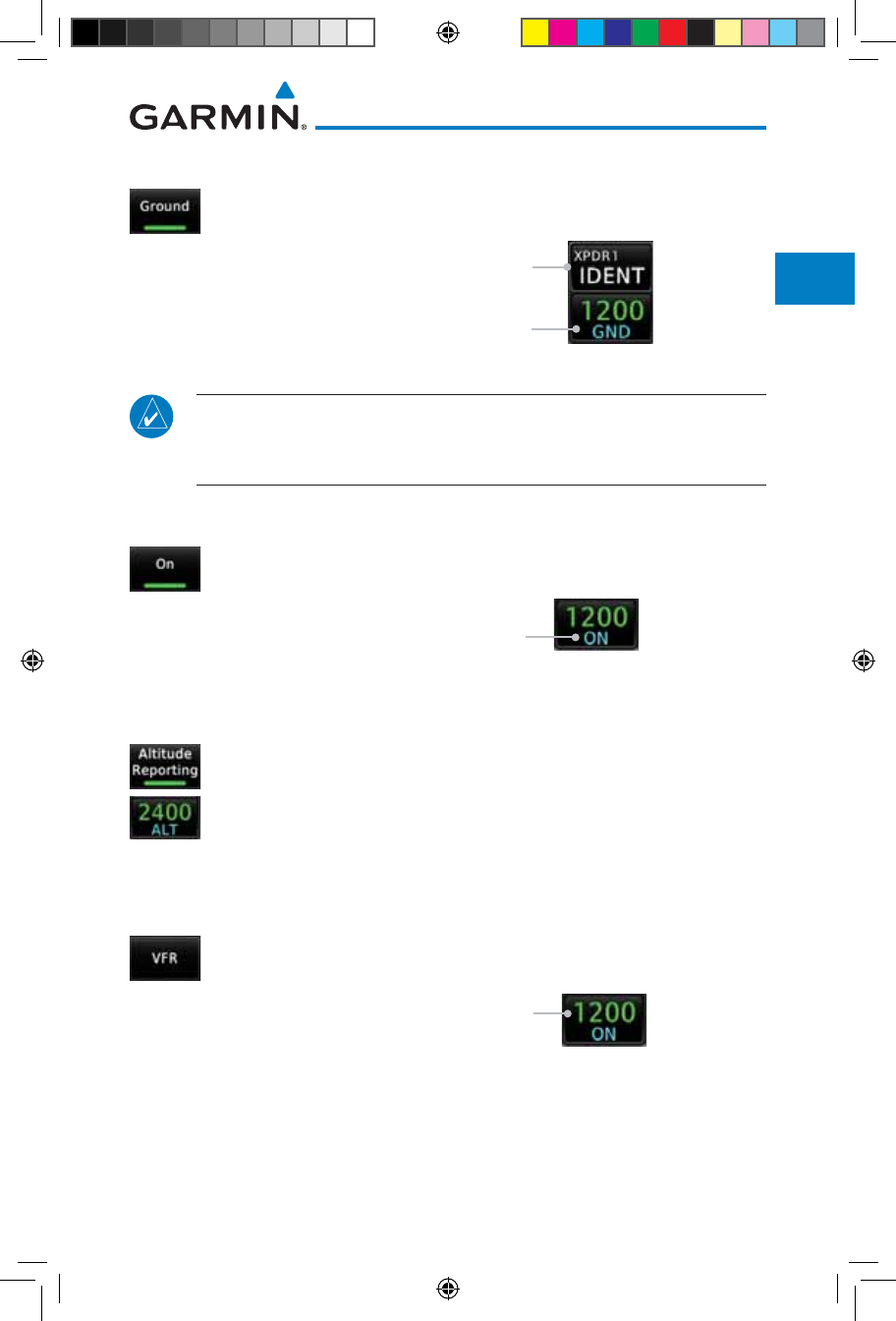
2-3190-01007-03 Rev. J
Garmin GTN 725/750 Pilot’s Guide
Foreword
Getting
Started
Audio &
Xpdr Ctrl
Com/Nav
FPL
Direct-To
Proc
Charts
Wpt Info
Map
Traffic
Terrain
Weather
Nearest
Services/
Music
Utilities
System
Messages
Symbols
Appendix
Index
2.1.4 Ground
Touch the Ground key to place the transponder into Ground
mode. Mode S replies will be allowed in Ground mode.
Active XPDR and IDENT Enabled
Transponder Operation "Ground" Mode
Figure 2-5 Transponder Mode "Ground" Indication
NOTE: Ground mode is not available with GTX 33/330 software version
8.00 or later. The GTN will automatically transition to Ground mode when
the aircraft is on the ground.
2.1.5 On
Touch the On key for Mode A operation. The transponder is
"On" and will transmit its squawk code when interrogated.
Transponder Operation "ON" Mode
Figure 2-6 Transponder Mode "ON" Indication
2.1.6 Altitude Reporting
1. Touch the Altitude Reporting key for Mode C operation.
2. The transponder will be "On" and will transmit its squawk
code and altitude when interrogated. An "ALT" annunciation
will appear when the squawk code is transmitted.
2.1.7 VFR
Touch the VFR key to set the VFR squawk code (1200).
VFR (1200) Transponder Squawk Code
Figure 2-7 Transponder VFR Squawk Code
190-01007-03-Final.indb 3 7/9/2015 2:06:53 PM
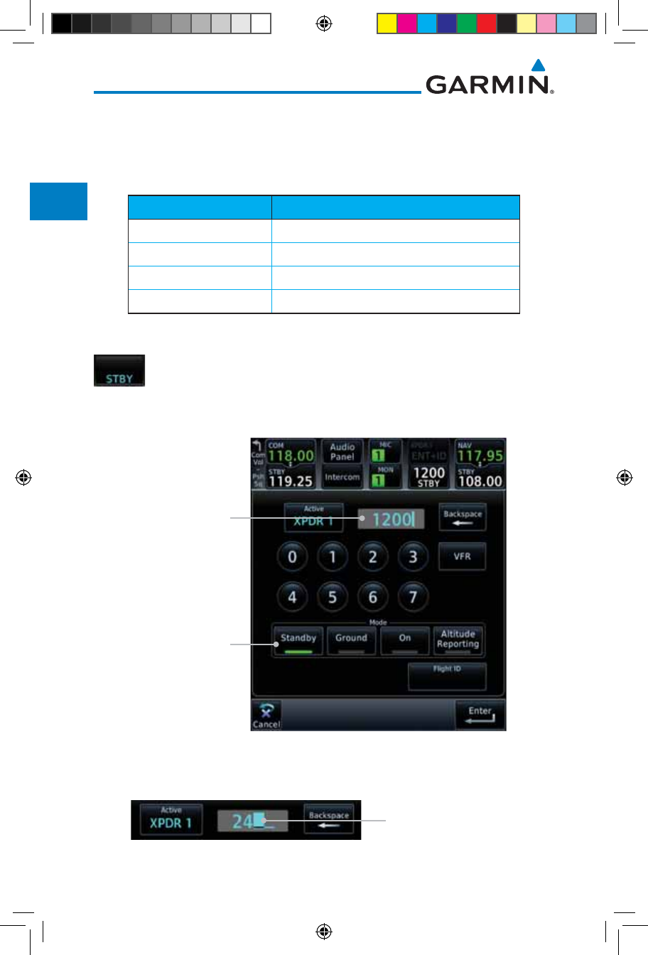
2-4
Garmin GTN 725/750 Pilot’s Guide
190-01007-03 Rev. J
Foreword
Getting
Started
Audio &
Xpdr Ctrl
Com/Nav
FPL
Direct-To
Proc
Charts
Wpt Info
Map
Traffic
Terrain
Weather
Nearest
Services/
Music
Utilities
System
Messages
Symbols
Appendix
Index
2.1.8 Selecting a Squawk Code
The selected squawk code will always be in use. As you change a squawk
code, the original code will be used until you are finished selecting the new
code.
Squawk Code Description
1200 Default VFR code in the USA
7500 Hijacking
7600 Loss of Communications
7700 Emergency
Table 2-1 XPDR Special Squawk Codes
1. Touch the transponder squawk code window at the top of the
display.
2. The XPDR page will be displayed. The Squawk Code value will
be active for selection for use by the active Transponder.
Active Squawk
Code Selection
Transponder Is In
Standby Mode
Figure 2-8 XPDR Squawk Code Selection Display
3. Touch the numeric keypad, or use the rotary knobs, to select
the desired Squawk Code.
Squawk Code Character
Selected For Editing
Figure 2-9 Selected XPDR Squawk Code
190-01007-03-Final.indb 4 7/9/2015 2:06:53 PM
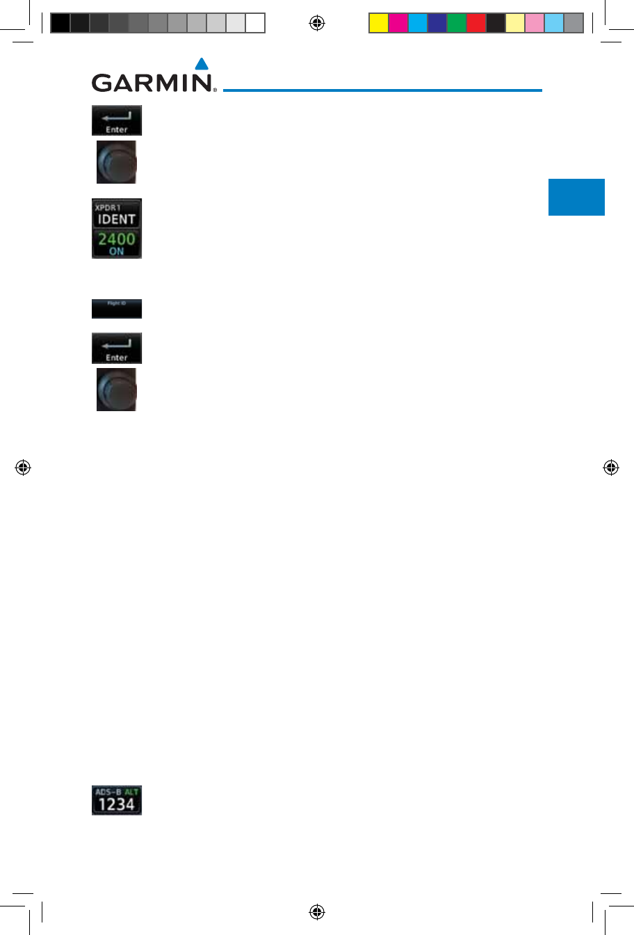
2-5190-01007-03 Rev. J
Garmin GTN 725/750 Pilot’s Guide
Foreword
Getting
Started
Audio &
Xpdr Ctrl
Com/Nav
FPL
Direct-To
Proc
Charts
Wpt Info
Map
Traffic
Terrain
Weather
Nearest
Services/
Music
Utilities
System
Messages
Symbols
Appendix
Index
4. Then, touch Enter or press the small right knob.
5. The selected Squawk Code will be shown in the XPDR window
at the top of the display.
2.1.9 Flight ID
1. While viewing the transponder page, touch the Flight ID key.
2. Touch the numeric keypad, or use the rotary knobs, to select the
desired Flight ID number and then press Enter. The selected
number will be shown in the Flight ID key.
2.1.10 GDL 88 ADS-B Reporting
The GDL 88 is a remote-mount ADS-B transceiver that sends ADS-B out
messages to ATC and other aircraft and communicates ADS-B In data to panel-
mounted avionics for the display of traffic and weather. Reference the GDL
88 Pilot Guide for a full description of GDL 88 functions. When a GTN is
interfaced to a GDL88 transceiver for ADS-B Out functions the GTN can control
some aspects of the ADS-B Out message and the GTN may provide position
information to the GDL88. The display and control of the information sent
depends on the equipment installed and how it is configured. Some installations
allow control by the pilot of the information sent, while others do not.
The Anonymous Mode, when armed, will replace the identifying information
in the ADS-B Out message with a temporary randomized number for privacy
while the position information will still be provided. The call sign will be sent as
"VFR." To enable Anonymous Mode, the Squawk Code must be set to the VFR
code (based on the GDL 88 configuration) and the Anonymous key must be
selected.
Viewing the ADS-B Control Panel Without Integrated Transponder Control
1. Touch the Transponder window to view the ADS-B control
panel.
190-01007-03-Final.indb 5 7/9/2015 2:06:53 PM
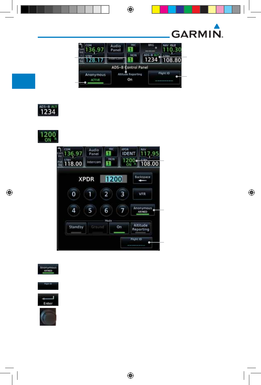
2-6
Garmin GTN 725/750 Pilot’s Guide
190-01007-03 Rev. J
Foreword
Getting
Started
Audio &
Xpdr Ctrl
Com/Nav
FPL
Direct-To
Proc
Charts
Wpt Info
Map
Traffic
Terrain
Weather
Nearest
Services/
Music
Utilities
System
Messages
Symbols
Appendix
Index
Touch To View
ADS-B Control
Panel
Touch To Select
Flight ID
Altitude
Reporting
Status
Touch To Toggle
Anonymous
Mode
Figure 2-10 ADS-B Control Panel
2. Touch the ADS-B window again to return to the previous
display.
Viewing the ADS-B Control Panel With Integrated Transponder Control
1. Touch the Transponder window to view the ADS-B control
panel.
Touch To View
Transponder and
ADS-B Control Panel
Touch To Select
Flight ID
Touch To Toggle
Anonymous Mode
Figure 2-11 ADS-B/Transponder Control Panel
2. Touch the Anonymous Mode key to toggle arming the
Anonymous mode.
3. While viewing the transponder page, touch the Flight ID key.
4. Touch the numeric keypad, or use the rotary knobs, to select
the desired Flight ID number and then press Enter.
190-01007-03-Final.indb 6 7/9/2015 2:06:54 PM
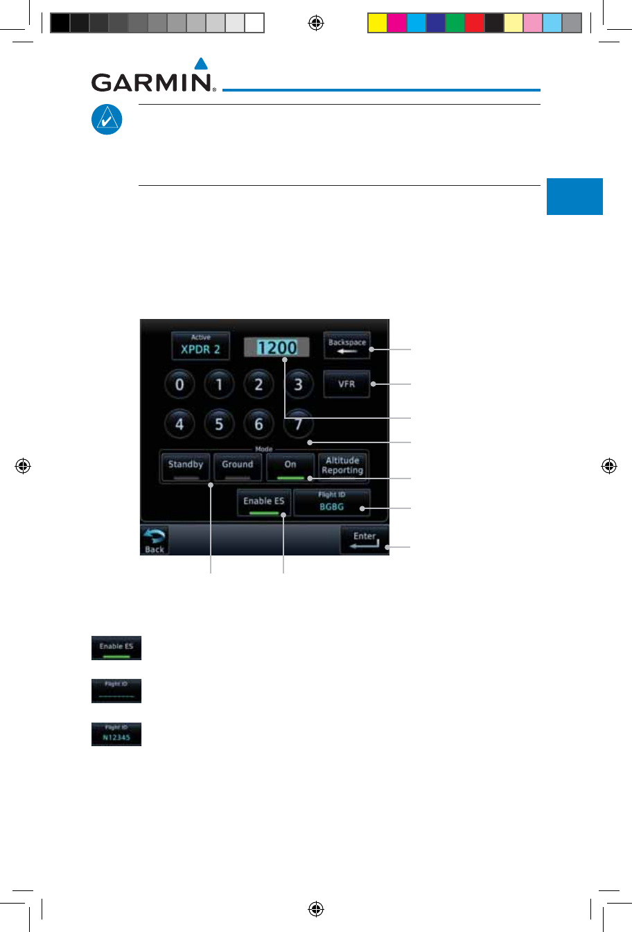
2-7190-01007-03 Rev. J
Garmin GTN 725/750 Pilot’s Guide
Foreword
Getting
Started
Audio &
Xpdr Ctrl
Com/Nav
FPL
Direct-To
Proc
Charts
Wpt Info
Map
Traffic
Terrain
Weather
Nearest
Services/
Music
Utilities
System
Messages
Symbols
Appendix
Index
NOTE: Changing the flight ID while in anonymous mode wouldn't actually
change the flight ID because a randomized ID is being broadcast. If the
ANONYMOUS key is armed, change the squawk code to the VFR code to
activate Anonymous mode.
2.1.11 Extended Squitter Transmission
The GTX 33ES is a remote mount transponder that functions as a transponder
and also sends ADS-B Out message to ATC and other aircraft. The GTN can act
as a control for a GTX 33 transponder including Extended Squitter functions.
When “Enable ES” is selected, the GTX 33/330 turns on Extended Squitter (ES)
transmissions.
VFR Squawk
Code (1200) Key
Squawk Code
Window
Squawk Code
Backspace Key
Enter Key
Numeric Keypad
Green Bar Indicates
"Active" Condition
Transponder
Mode Keys
Touch To Enter
Flight ID
Touch To Toggle
Extended Squitter
Figure 2-12 Transponder Control Panel With Extended Squitter Capability
1. While viewing the Transponder (XPDR) page, touch the Enable
ES key to toggle Extended Squitter Off and On.
2. Touch the Flight ID key and use the keypad to select a Flight
ID and then touch Enter.
3. After selecting a Flight ID, the selected value will be shown in
the Flight ID key.
190-01007-03-Final.indb 7 7/9/2015 2:06:54 PM
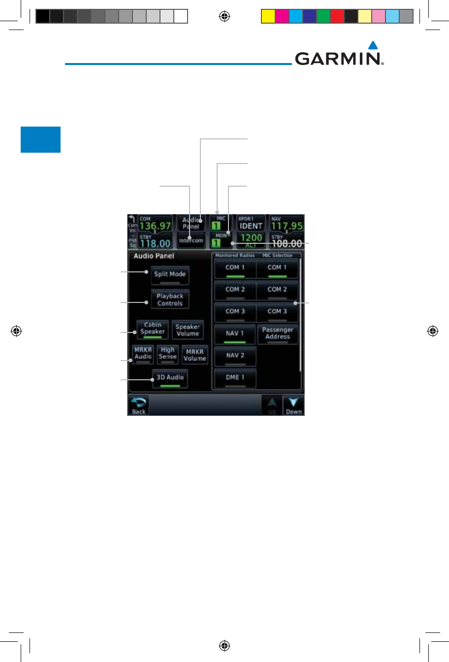
2-8
Garmin GTN 725/750 Pilot’s Guide
190-01007-03 Rev. J
Foreword
Getting
Started
Audio &
Xpdr Ctrl
Com/Nav
FPL
Direct-To
Proc
Charts
Wpt Info
Map
Traffic
Terrain
Weather
Nearest
Services/
Music
Utilities
System
Messages
Symbols
Appendix
Index
2.2 Audio Panel Operation
The GTN 7XX can operate as a control head for remotely connected
compatible audio and intercom equipment (such as the Garmin GMA 35).
Intercom Setup
Monitor and
Mic Selections
Audio Panel Controls
Touch To Display
Mon Selection:
1, 2 or 3
Activates Split
Mode
Cabin Speaker
Select & Vol
Mic Selection: 1, 2 or 3
"+" Indicates Additional Audio Source
Monitoring (Nav, DME, or ADF)
Marker Audio
And Volume
3D Audio
Recorder
Playback
Control
Figure 2-13 Audio Panel Controls
190-01007-03-Final.indb 8 7/9/2015 2:06:54 PM
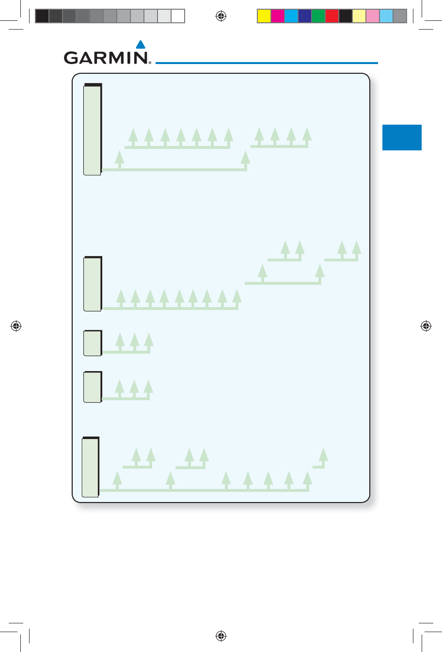
2-9190-01007-03 Rev. J
Garmin GTN 725/750 Pilot’s Guide
Foreword
Getting
Started
Audio &
Xpdr Ctrl
Com/Nav
FPL
Direct-To
Proc
Charts
Wpt Info
Map
Traffic
Terrain
Weather
Nearest
Services/
Music
Utilities
System
Messages
Symbols
Appendix
Index
Radio &Mic Selection
Monitored Radios
Com 1
Com 2
Com 3
Nav 1
Nav 2
DME
ADF
MIC Selection
Com 1
Com 2
Com 3
Passenger
Address
Mic
1
2
3
Mon
1
2
3
Audio Panel
Split Mode
Playback Controls
Cabin Speaker
Speaker Volume
Marker Audio
Marker Volume
Marker Hi Sense
3D Audio
Crew Intercom
Pilot Radios
Com 1
Passenger Address
Co-Pilot Radios
Com 1
Passenger Address
Intercom Setup
Pilot VOL/SQ
Volume
Squelch
Co-Pilot VOL/SQ
Volume
Squelch
Music 1
Telephone
Music 2
Menu
Group Co-Pilot
with Passenger
Bluetooth Audio
Figure 2-14 Audio Panel Functional Diagram
190-01007-03-Final.indb 9 7/9/2015 2:06:54 PM
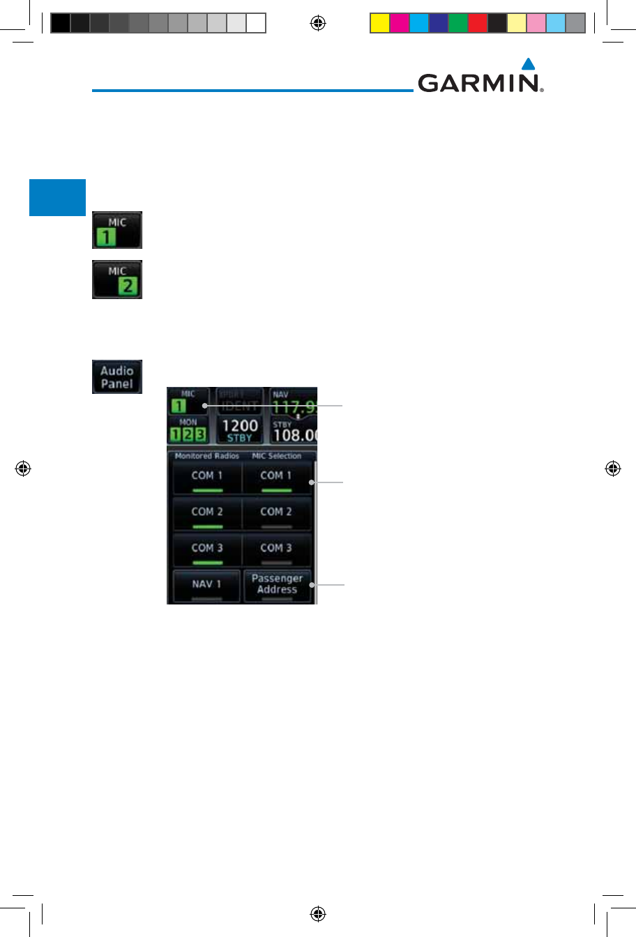
2-10
Garmin GTN 725/750 Pilot’s Guide
190-01007-03 Rev. J
Foreword
Getting
Started
Audio &
Xpdr Ctrl
Com/Nav
FPL
Direct-To
Proc
Charts
Wpt Info
Map
Traffic
Terrain
Weather
Nearest
Services/
Music
Utilities
System
Messages
Symbols
Appendix
Index
2.2.1 Mic Selection
Mic selection can be determined by two methods: the Mic window or by the
Audio Panel page.
2.2.1.1 Mic Window Mic Selection
1. Touch the Mic window to toggle between Mic 1 and Mic 2.
2. Note that the selected Mic is automatically monitored.
3. If Mic 3 or Passenger Address (PA) are selected, touching the
Mic window will revert to toggling between Mic 1 and Mic 2.
2.2.1.2 Audio Panel Page Mic Selection
1. Touch the Audio Panel key at the top of the display.
Selected Mic
Mic Selection: 1, 2 or 3
Passenger Address Mic
Selection
Figure 2-15 Audio Panel MIC Selection
2. Touch the desired Mic (Com 1, Com 2, or Com 3) from the
MIC Selection list on the right side of the display.
3. The selected Mic will be shown in the Mic window.
190-01007-03-Final.indb 10 7/9/2015 2:06:54 PM
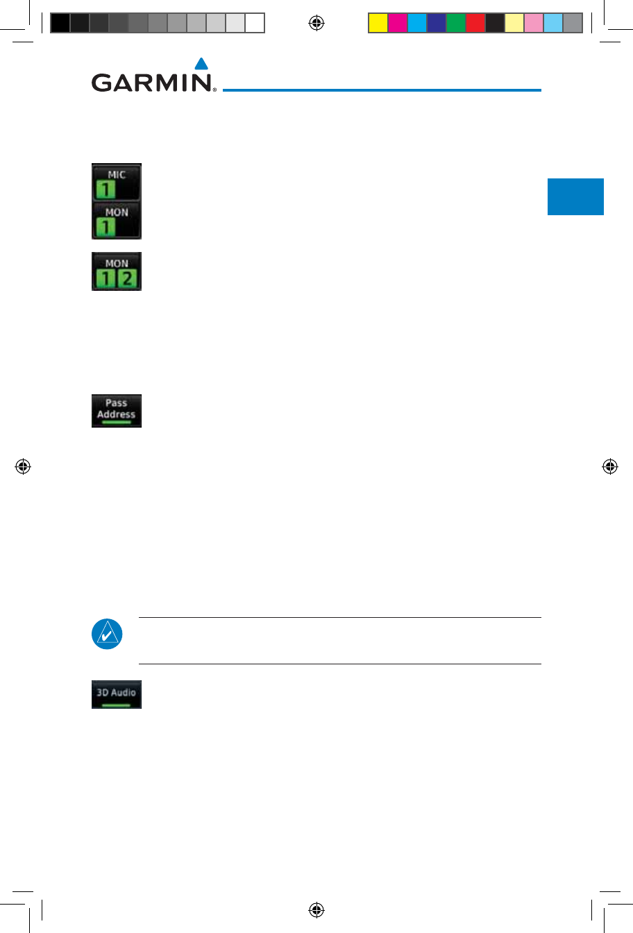
2-11190-01007-03 Rev. J
Garmin GTN 725/750 Pilot’s Guide
Foreword
Getting
Started
Audio &
Xpdr Ctrl
Com/Nav
FPL
Direct-To
Proc
Charts
Wpt Info
Map
Traffic
Terrain
Weather
Nearest
Services/
Music
Utilities
System
Messages
Symbols
Appendix
Index
2.2.2 Monitor
The Monitor function indicates which radios are being listened to.
1. Monitor is automatically selected for the associated Com Mic
Radio (1, 2, or 3). For example, when Com 1 is selected, Mon
1 is automatically active.
2. Touch the Mon key to toggle between the automatically
selected monitored channel (selected Mic) and the other
channels.
2.2.3 Passenger Address
The Passenger Address key toggles the passenger address system on and
off.
Touch the Passenger Address key to toggle the passenger
address system on and off.
2.2.4 3D Audio
Advanced processing adjusts audio in the headset to mimic how the human
ear normally hears and registers sounds in space. This 3-D Audio feature makes
it seem as though different audio sources are coming from different directions
around you. Now it’s much easier to focus on and understand one particular
source from among many. For example, COM 1 will seem to be coming from
the left while COM 2 will seem to be coming from the right. When 3D Audio is
disabled, balance is restored.
NOTE: The stereo/mono headsets must be in the stereo position in order
for 3D audio to function.
Touch the 3D Audio key to toggle the 3D Audio function on
and off.
This is currently done such that audio sources will either be 30 degrees
to your left (330 degrees), 30 degrees to your right, and directly in front (0
degrees). The following table details the left/right balance of the audio level
depending on the selected Com:
190-01007-03-Final.indb 11 7/9/2015 2:06:54 PM
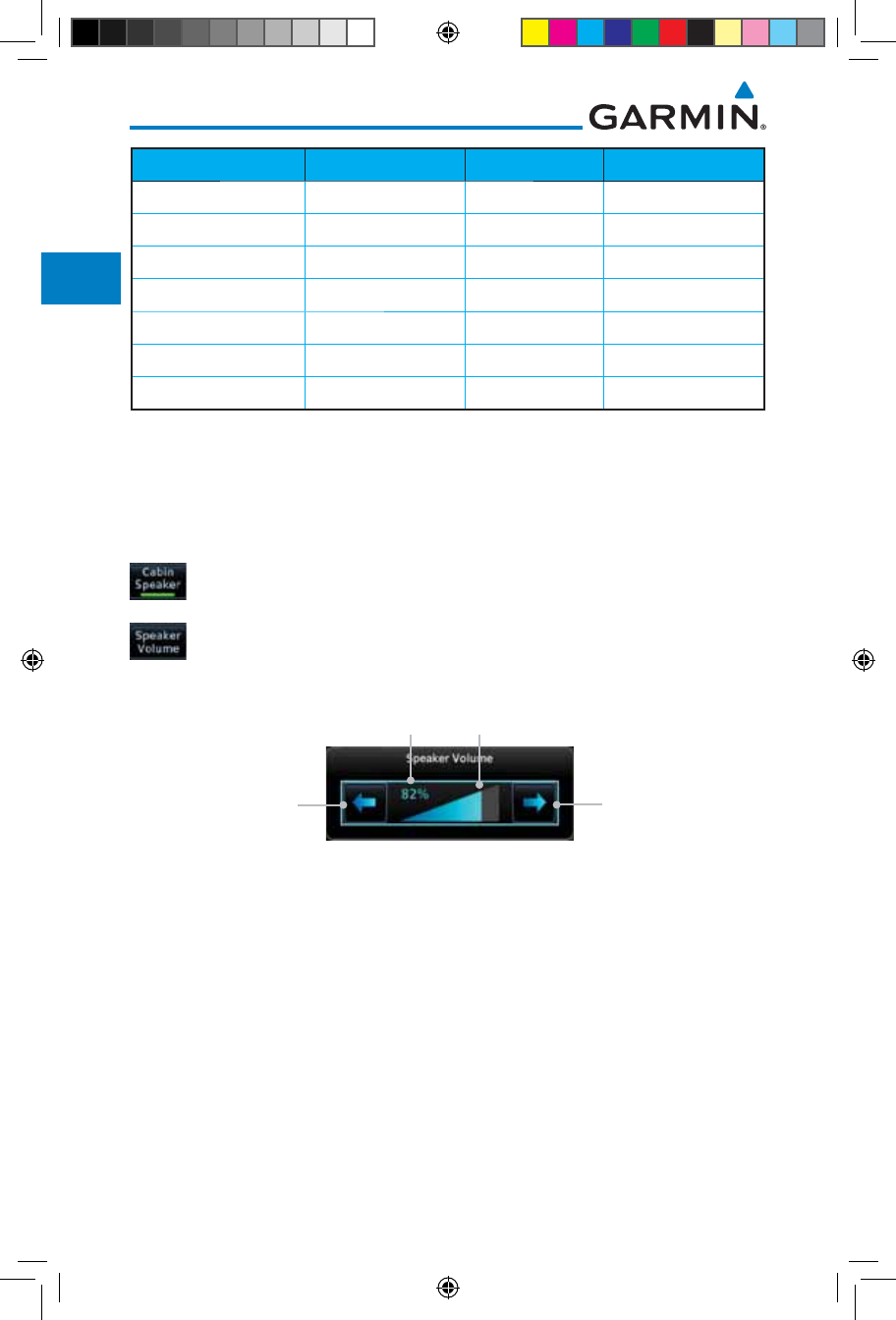
2-12
Garmin GTN 725/750 Pilot’s Guide
190-01007-03 Rev. J
Foreword
Getting
Started
Audio &
Xpdr Ctrl
Com/Nav
FPL
Direct-To
Proc
Charts
Wpt Info
Map
Traffic
Terrain
Weather
Nearest
Services/
Music
Utilities
System
Messages
Symbols
Appendix
Index
Active Com 1 2 3
1,2,3 330 0 30
1,2 330 30 N/A
1,3 330 N/A 30
2,3 N/A 330 30
1 0 N/A N/A
2 N/A 0 N/A
3 N/A N/A 0
Table 2-2 3D Audio Left/Right Balance
2.2.5 Cabin Speaker Selection and Volume
The Cabin Speaker key turns the cabin speaker on and off. The Speaker
Volume key sets the volume level.
1. Touch the Cabin Speaker key to toggle the cabin speaker
on and off.
2. Touch the Speaker Volume key to set the Cabin Speaker
volume. Touch the Speaker Volume arrows to set the
volume.
Touch To
Increase Volume
Touch To
Decrease Volume
Percent Of Maximum Volume Graphic Scale Showing Volume
Figure 2-16 Cabin Speaker Volume Selection
190-01007-03-Final.indb 12 7/9/2015 2:06:55 PM
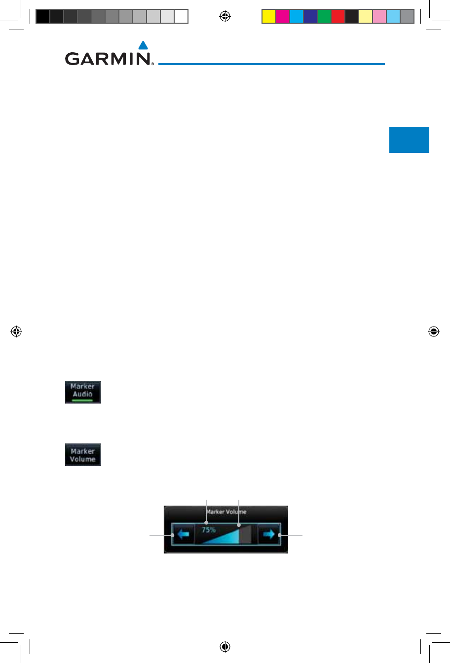
2-13190-01007-03 Rev. J
Garmin GTN 725/750 Pilot’s Guide
Foreword
Getting
Started
Audio &
Xpdr Ctrl
Com/Nav
FPL
Direct-To
Proc
Charts
Wpt Info
Map
Traffic
Terrain
Weather
Nearest
Services/
Music
Utilities
System
Messages
Symbols
Appendix
Index
2.2.6 Marker Audio and Volume
The optional Marker Beacon Receiver uses an audio indicator to alert you
when the aircraft passes over a Marker Beacon transmitter. The audio from the
Marker Beacon Receiver can be heard unless disabled by selecting Marker Audio.
When Marker is selected (green bar shown), the tones for Marker Beacons are
heard. When Marker is not selected (green bar not shown), the tones for Marker
Beacons are not heard.
The GMA 35 marker beacon receiver and indicators are part of the ILS system.
The marker beacon lamps operate independently of any audio selection and
cannot be turned off. The GMA 35 can drive external marker lamps if required
and also provides an autopilot middle marker sense output.
Prior to beginning an ILS approach, select high or low marker sensitivity with
the Marker Hi Sense key. The lighted green bar in the key illuminates for high
sensitivity and remains off for low sensitivity.
Touching the Marker Audio key prior to an approach allows the marker
audio tones to be heard in the headsets. When the green bar in the Marker
Audio key shows, the marker audio will be heard when available. The Audio
Panel key will change to a Mute key. Touching the Mute key while audio is
heard will mute the marker audio until the next beacon is received. The marker
beacon signal sensitivity threshold can be set in Configuration mode. Contact a
Garmin-authorized service center for adjustment.
1. While the Audio Control page is displayed, touch the Marker
Audio key to hear the current Marker Beacon tones.
2. Touch the Marker Audio key again to disable Marker Beacon
tones.
3. Touch the Marker Volume key to set the Marker Beacon
tone volume. Touch the Marker Volume arrows to set the
volume.
Touch To
Increase Volume
Touch To
Decrease Volume
Percent Of Maximum Volume Graphic Scale Showing Volume
Figure 2-17 Audio Panel Marker Beacon Tone Volume Selection
190-01007-03-Final.indb 13 7/9/2015 2:06:55 PM

2-14
Garmin GTN 725/750 Pilot’s Guide
190-01007-03 Rev. J
Foreword
Getting
Started
Audio &
Xpdr Ctrl
Com/Nav
FPL
Direct-To
Proc
Charts
Wpt Info
Map
Traffic
Terrain
Weather
Nearest
Services/
Music
Utilities
System
Messages
Symbols
Appendix
Index
2.2.7 Marker Hi Sense
The Marker Hi Sense setting allows detecting the outer Marker Beacon from
a greater distance.
1. While the Audio Control page is displayed, touch the Marker
Hi Sense key to activate greater Marker Beacon sensitivity.
2. Touch the Marker Hi Sense key again to return to normal
sensitivity.
2.2.8 Marker Beacon Annunciations
A visual annunciation of marker beacons will be shown on the display when
the aircraft flies over a marker beacon. The annunciation will appear in the
lower left of the display.
Current Beacon Icon (Standard) Icon (Blink) Blink Interval
Inner Marker 250 ms
Middle Marker 333 ms
Outer Marker 750 ms
The marker beacon alternates between the standard icon and the blink icon at
the blink interval corresponding to the current beacon.
Table 2-3 Marker Beacons
190-01007-03-Final.indb 14 7/9/2015 2:06:55 PM
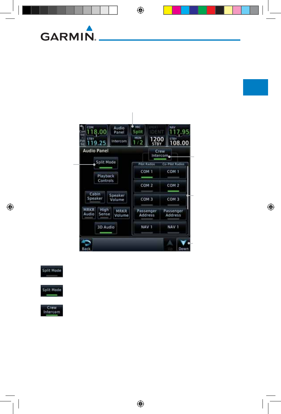
2-15190-01007-03 Rev. J
Garmin GTN 725/750 Pilot’s Guide
Foreword
Getting
Started
Audio &
Xpdr Ctrl
Com/Nav
FPL
Direct-To
Proc
Charts
Wpt Info
Map
Traffic
Terrain
Weather
Nearest
Services/
Music
Utilities
System
Messages
Symbols
Appendix
Index
2.2.9 Audio Split Mode
In Split Mode the pilot uses one radio for MIC audio while the copilot uses a
different radio. The pilot and copilot can transmit simultaneously over separate
radios. The pilot can still listen to their individually selected radios. In the Split
mode, the pilot and co-pilot may talk and listen independently to the radios (or
PA) as selected.
Crew Intercom
Activation
Select Audio
Split Mode
Touch And Drag
Finger To Scroll List
of Radio Selections
Touch To Scroll List
of Radio Selections
Split Mode Annunciation
Figure 2-18 Audio Panel Split Mode Controls
1. While the Audio Control page is displayed, touch the Split
Mode key to display the Crew Intercom selections.
2. Touch the Split Mode key again to toggle the Crew Intercom
selection off.
3. Touch the Crew Intercom key to toggle activation of the
Crew Intercom allowing the Pilot and Co-Pilot to talk to each
other.
4. Touch the desired Pilot and Co-Pilot Radio selections.
190-01007-03-Final.indb 15 7/9/2015 2:06:55 PM
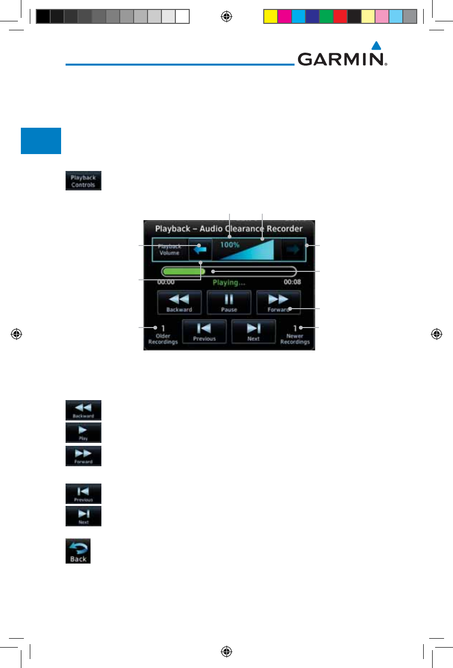
2-16
Garmin GTN 725/750 Pilot’s Guide
190-01007-03 Rev. J
Foreword
Getting
Started
Audio &
Xpdr Ctrl
Com/Nav
FPL
Direct-To
Proc
Charts
Wpt Info
Map
Traffic
Terrain
Weather
Nearest
Services/
Music
Utilities
System
Messages
Symbols
Appendix
Index
2.2.10 Playback Controls
The voice recorder feature records all the audio heard on any selected COM
radio that is selected for transmission (the MIC selected COM) and not others
selected for monitoring only. Playback is heard by anyone listening on the
selected radios. The Clearance Recorder can record up to 2.5 minutes of Com
audio.
1. While the Audio Control page is displayed, touch the Playback
Controls key to display the Playback Control selections.
Recording Time
Line
Playback Controls
Number Of
Recordings Made
After The Current
Selection
Number Of
Recordings
Made Before
The Current
Selection
Touch To
Increase Volume
Touch To
Decrease Volume
Percent Of Maximum Volume Graphic Scale Showing Volume
Heavy Outline
Indicates The Upper
Left Rotary Knob
Controls Volume
Figure 2-19 Audio Panel Playback Controls
2. Touch the Playback Volume arrows to set the volume.
3. Touch the Backward, Play, or Forward keys to control the
playback of the currently selected recording.
4. Touch the Previous or Next keys to select a recording.
5. Touch the Back key to return to the Audio Panel page.
190-01007-03-Final.indb 16 7/9/2015 2:06:55 PM
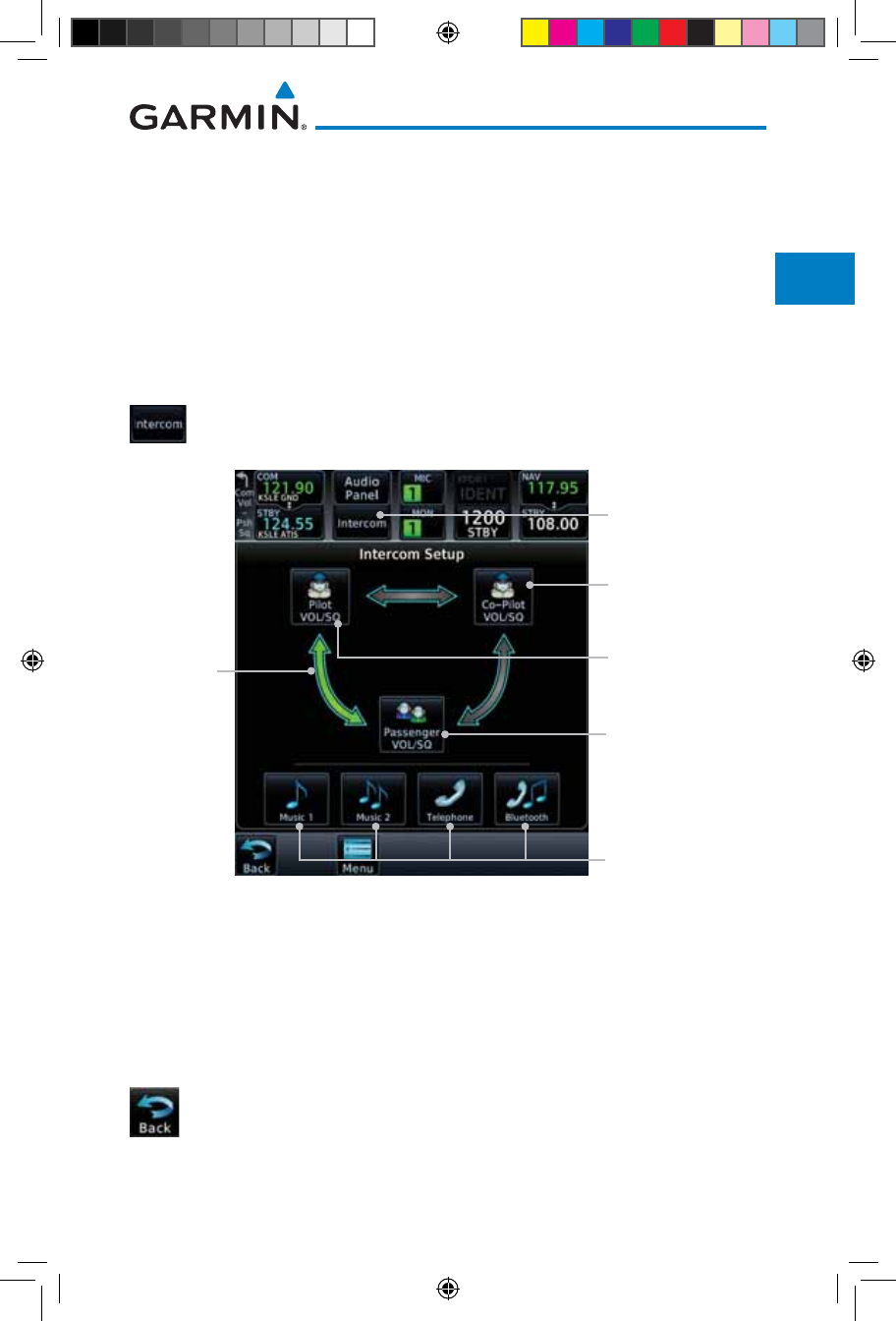
2-17190-01007-03 Rev. J
Garmin GTN 725/750 Pilot’s Guide
Foreword
Getting
Started
Audio &
Xpdr Ctrl
Com/Nav
FPL
Direct-To
Proc
Charts
Wpt Info
Map
Traffic
Terrain
Weather
Nearest
Services/
Music
Utilities
System
Messages
Symbols
Appendix
Index
2.3 Intercom Setup
The GTN 7XX can operate as a control head for remotely connected
compatible intercom equipment. The Internal Communication System (ICS)
has several modes of operation that are selected on the display of the GTN 7XX
to control communication in the aircraft. Passengers cannot transmit over the
active Com radio, even if equipped with a PTT key.
Depending on the installation and aircraft, the pilot and co-pilot positions on
this page may be reversed (such as configured for rotorcraft).
1. Touch the Intercom window at the top of the display to
display the Intercom Setup page.
Touch Source
To Configure
Touch To Display
Intercom Setup
Touch To Configure
Co-Pilot Volume
And Squelch
Touch To Configure
Passenger Volume
And Squelch
Touch To Configure
Pilot Volume And
Squelch
Selected
Intercom
Mode
Figure 2-20 Intercom Setup
2. Touch the arrow between the intercom recipients to activate
communication between those recipients. The arrow will be
green when communication is active. Touch the arrow again
to deactivate communication. Detailed information is shown
in the Intercom Modes table.
3. Touch the key for a function to the make the desired changes to
their setup. Then, touch the Back key to return to the Intercom
Setup page.
190-01007-03-Final.indb 17 7/9/2015 2:06:56 PM
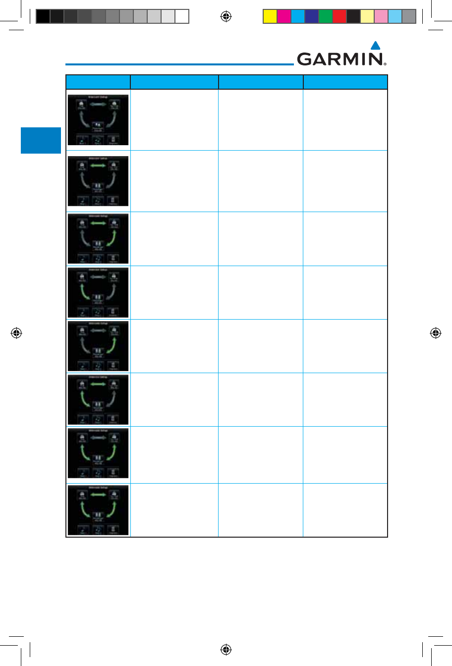
2-18
Garmin GTN 725/750 Pilot’s Guide
190-01007-03 Rev. J
Foreword
Getting
Started
Audio &
Xpdr Ctrl
Com/Nav
FPL
Direct-To
Proc
Charts
Wpt Info
Map
Traffic
Terrain
Weather
Nearest
Services/
Music
Utilities
System
Messages
Symbols
Appendix
Index
Mode Pilot Hears Co-Pilot Hears Passengers Hear
Selected radios, pilot Selected radios,
co-pilot
Passengers
Selected radios, pilot,
co-pilot
Selected radios, pilot,
co-pilot
Passengers
Selected radios, pilot,
co-pilot
Selected radios,
co-pilot, pilot,
passengers
Co-pilot, passengers
Selected radios, pilot,
passengers
Selected radios,
co-pilot
Pilot, passengers
Selected radios, pilot Selected radios,
co-pilot, passengers
Co-pilot, passengers
Selected radios, pilot,
co-pilot, passengers
Selected radios, pilot,
co-pilot
Selected radios, pilot,
passengers
Selected radios, pilot,
passengers
Selected radios,
co-pilot, passengers
Selected radios, pilot,
co-pilot, passengers
Selected radios, pilot,
co-pilot, passengers
Selected radios, pilot,
co-pilot, passengers
Selected radios, pilot,
co-pilot, passengers
Table 2-4 Intercom Modes
190-01007-03-Final.indb 18 7/9/2015 2:06:56 PM
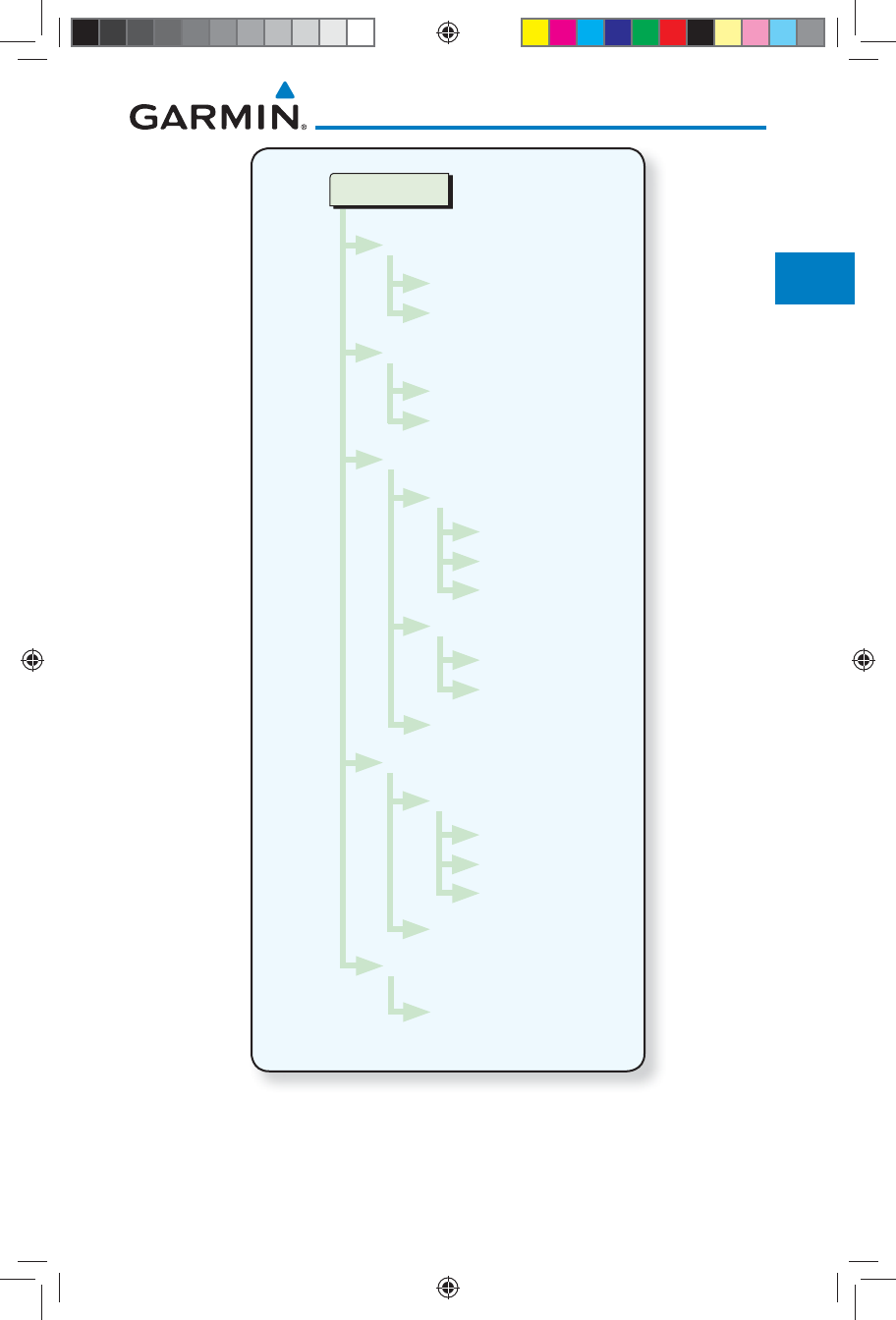
2-19190-01007-03 Rev. J
Garmin GTN 725/750 Pilot’s Guide
Foreword
Getting
Started
Audio &
Xpdr Ctrl
Com/Nav
FPL
Direct-To
Proc
Charts
Wpt Info
Map
Traffic
Terrain
Weather
Nearest
Services/
Music
Utilities
System
Messages
Symbols
Appendix
Index
Intercom Setup
Pilot VOL/SQ
Volume
Squelch
Co-Pilot VOL/SQ
Volume
Squelch
Music 1 & Music 2
Music Setup
Pilot
Co-Pilot
Passenger
Mute Music During...
Radio
Intercom
Music Volume
Telephone
Telephone Setup
Pilot
Co-Pilot
Passenger
Telephone Volume
Menu
Group Co-Pilot
with Passenger
Figure 2-21 Intercom Setup Functional Diagram
190-01007-03-Final.indb 19 7/9/2015 2:06:56 PM
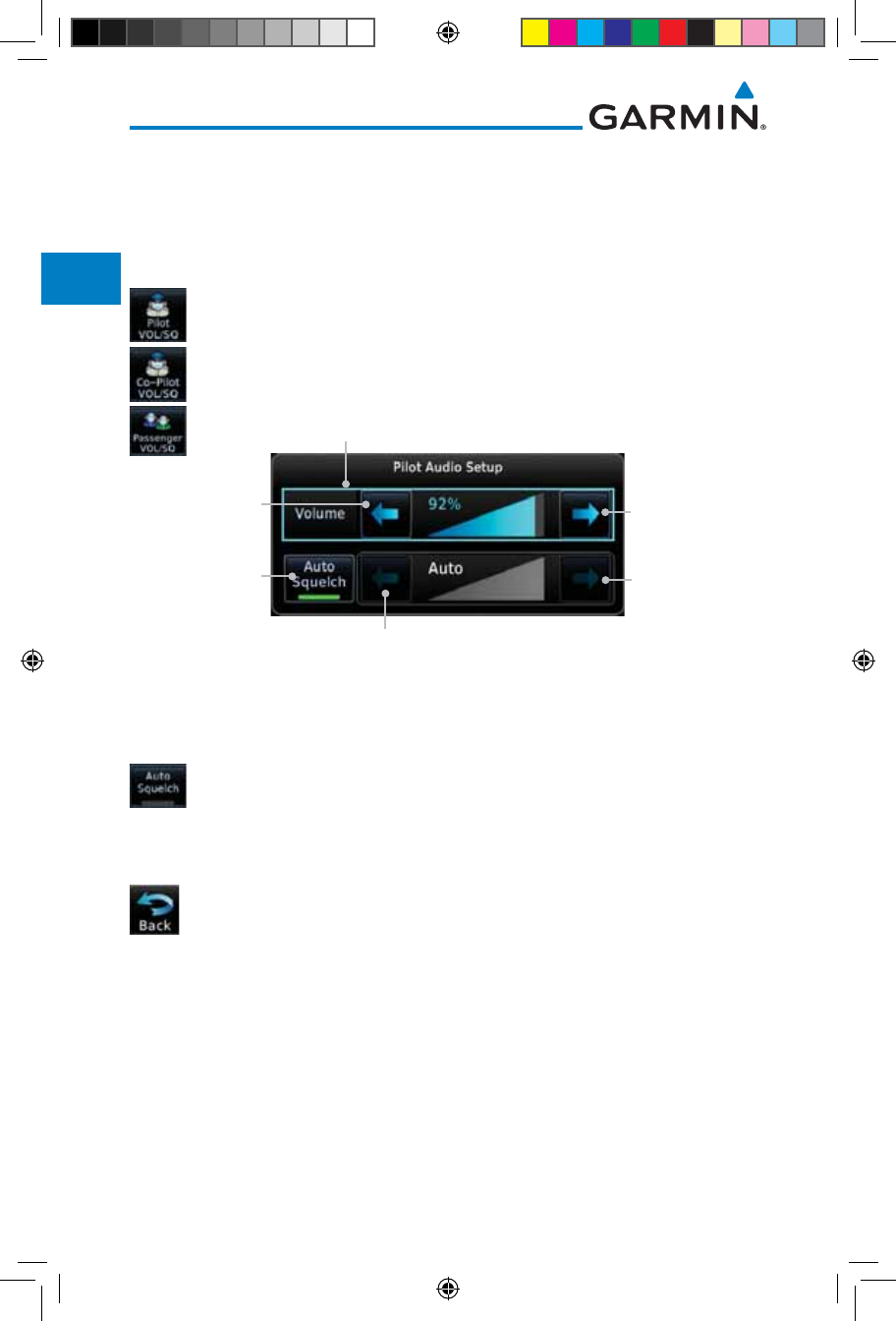
2-20
Garmin GTN 725/750 Pilot’s Guide
190-01007-03 Rev. J
Foreword
Getting
Started
Audio &
Xpdr Ctrl
Com/Nav
FPL
Direct-To
Proc
Charts
Wpt Info
Map
Traffic
Terrain
Weather
Nearest
Services/
Music
Utilities
System
Messages
Symbols
Appendix
Index
2.3.1 Set Pilot, Co-Pilot, & Passenger Volume and
Squelch
In the Intercom Setup function, the Volume and Squelch may be set separately for the
Pilot, Copilot, and Passenger intercoms.
1. While viewing the Intercom Setup page, touch the Pilot,
Co-Pilot, or Passenger VOL/SQ keys to set the Volume and
Squelch for the selected item.
Touch To Select
Manual Or Auto
Squelch
Touch To
Increase Volume
Touch To
Decrease
Volume
Heavy Outline Indicates The Upper Left Rotary
Knob Controls Volume
With Manual
Squelch, Touch To
Increase Squelch
With Manual Squelch,
Touch To Decrease Squelch
Figure 2-22 Pilot Audio Setup
2. Touch the Volume arrows to set the desired Volume level.
3. Touch the Auto Squelch key to allow the unit to set the
Squelch level automatically. When enabled, the Auto Squelch
key will display a green bar.
4. Touch the Squelch arrows to set the desired Squelch level.
5. Touch the Back key to return to the Intercom Setup page.
190-01007-03-Final.indb 20 7/9/2015 2:06:57 PM
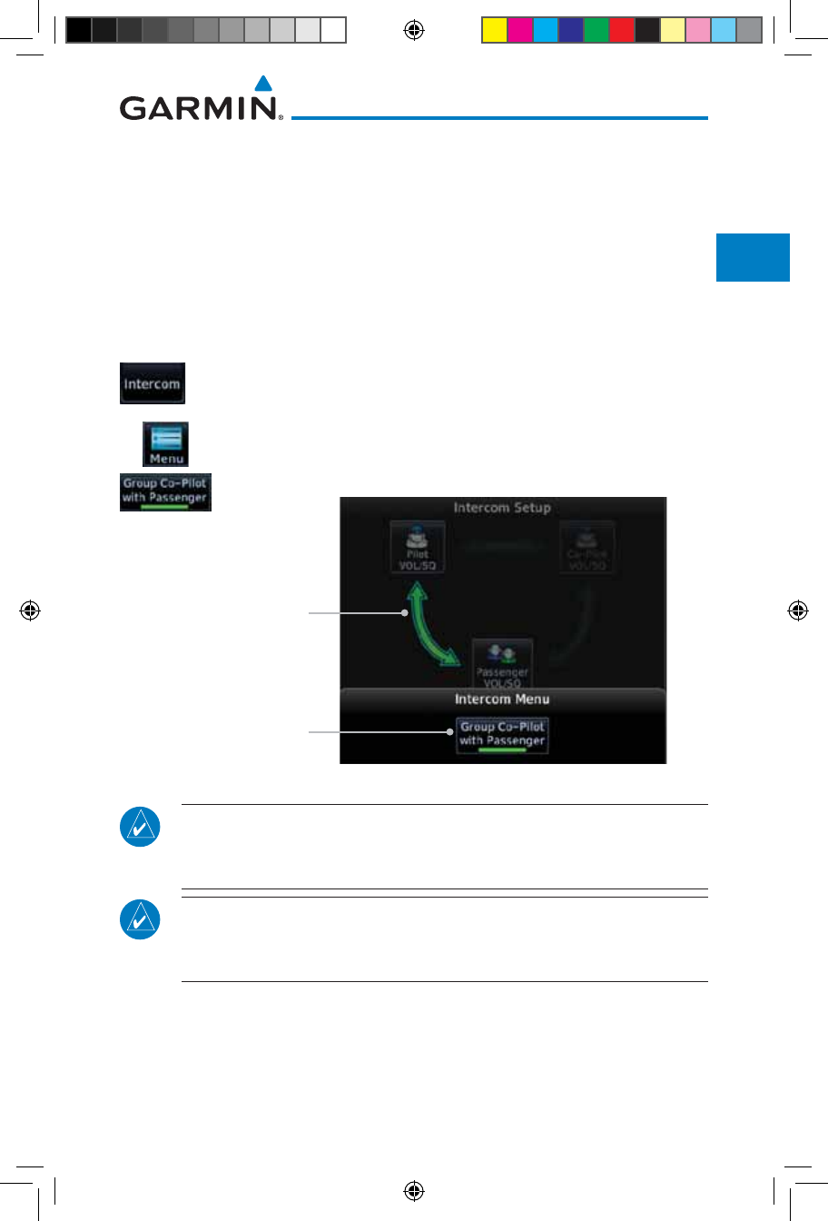
2-21190-01007-03 Rev. J
Garmin GTN 725/750 Pilot’s Guide
Foreword
Getting
Started
Audio &
Xpdr Ctrl
Com/Nav
FPL
Direct-To
Proc
Charts
Wpt Info
Map
Traffic
Terrain
Weather
Nearest
Services/
Music
Utilities
System
Messages
Symbols
Appendix
Index
2.3.2 Co-Pilot is Passenger
When the GTN 7XX is installed with a GMA 35, the GTN can place the GMA
into "Co-Pilot is Passenger" mode. While in this mode, the GMA 35 treats the
copilot headset as a passenger headset and the co-pilot only hears what the other
passengers hear. This applies to intercom audio, alerts (if configured for the
passengers), selected audio (if configured for passengers), and music/telephone
distribution. "Co-Pilot is Passenger" mode allows simpler audio control for the
pilot when the co-pilot is just a passenger and not involved in flying the aircraft.
1. To activate "Co-Pilot is Passenger" mode, open the Intercom
Setup page and touch Intercom.
2. Touch Menu, to display the Intercom Menu, and then touch
Group Co-Pilot with Passenger to enable "Co-Pilot is
Passenger" mode.
Selected Intercom
Configuration
Set Co-Pilot as
Passenger
Figure 2-23 Set Co-Pilot as a Passenger in Intercom
NOTE: This feature should not be used for multi-crew aircraft. When the
co-pilot is treated as a passenger, co-pilot position may not hear audio
alerts or radios.
NOTE: While this mode is active, the co-pilot intercom and audio controls
are unavailable because the co-pilot intercom/audio is controlled by the
passenger controls. Split mode is also unavailable.
190-01007-03-Final.indb 21 7/9/2015 2:06:57 PM
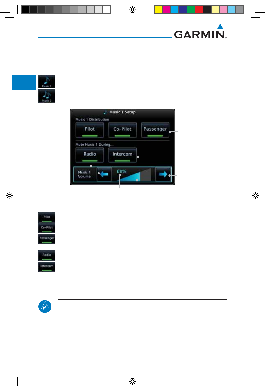
2-22
Garmin GTN 725/750 Pilot’s Guide
190-01007-03 Rev. J
Foreword
Getting
Started
Audio &
Xpdr Ctrl
Com/Nav
FPL
Direct-To
Proc
Charts
Wpt Info
Map
Traffic
Terrain
Weather
Nearest
Services/
Music
Utilities
System
Messages
Symbols
Appendix
Index
2.3.3 Music 1 and Music 2 Setup
The GMA 35 provides two music interfaces. Operation depends on the state of the
music distribution.
1. While viewing the Intercom Setup page, touch the Music 1
or Music 2 keys to set their setup.
Touch To Select
Music Recipients
Touch To Select Source
That Will Mute Music
Percent Of Maximum Volume Graphic Scale Showing Volume
Touch To
Increase Volume
Touch To
Decrease
Volume
Heavy Outline Indicates The Upper Left Rotary
Knob Controls Volume
Figure 2-24 Music 1 Setup
2. Select the recipients for Music Distribution by touching any
combination of the Pilot, Co-Pilot, or Passenger keys.
3. Touch the Radio and/or Intercom keys to select the function
that, when active, Music will be muted.
4. Touch the Volume arrows to set the desired Volume level.
NOTE: At every power cycle, the “mute music during radio” selection will
be active.
190-01007-03-Final.indb 22 7/9/2015 2:06:57 PM
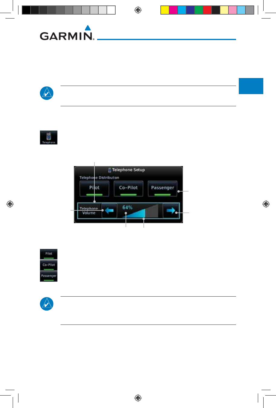
2-23190-01007-03 Rev. J
Garmin GTN 725/750 Pilot’s Guide
Foreword
Getting
Started
Audio &
Xpdr Ctrl
Com/Nav
FPL
Direct-To
Proc
Charts
Wpt Info
Map
Traffic
Terrain
Weather
Nearest
Services/
Music
Utilities
System
Messages
Symbols
Appendix
Index
2.3.4 Telephone Setup
The GMA 35 provides a 2-way telephone interface. Operation depends on
the state of the telephone distribution. Telephone communication is much like
using the intercom, allowing both parties to talk at once.
NOTE: Garmin recommends when using the GSR 56 Iridium phone system
that the audio only be activated when on a phone call.
The telephone channel may be disabled in Configuration mode. Contact a
Garmin-authorized service center for details.
1. While viewing the Intercom Setup page, touch the Telephone
key to set its setup.
Percent Of Maximum Volume Graphic Scale Showing Volume
Touch To Select
Telephone Recipients
Touch To
Increase Volume
Touch To
Decrease
Volume
Heavy Outline Indicates The Upper Left Rotary
Knob Controls Volume
Figure 2-25 Telephone Setup
2. Select the recipients for Telephone Distribution by touching
any combination of the Pilot, Co-Pilot, or Passenger keys.
3. Touch the Volume arrows to set the desired Telephone Volume
level.
NOTE: Telephone audio distribution is retained across power cycles for the
passengers, however, pilot and co-pilot telephone distribution will default
to OFF over power cycles.
190-01007-03-Final.indb 23 7/9/2015 2:06:58 PM
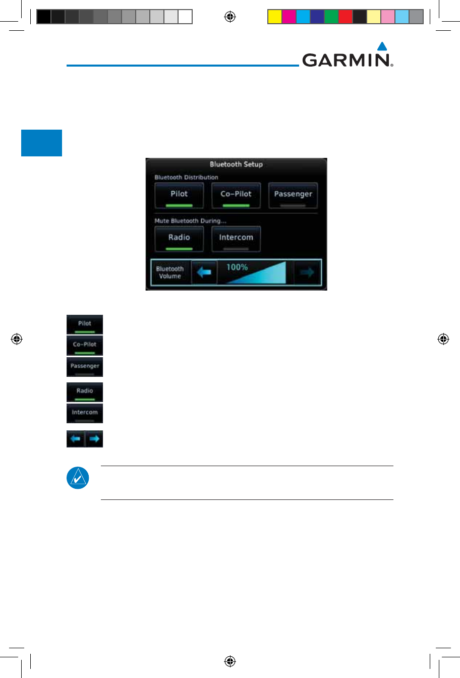
2-24
Garmin GTN 725/750 Pilot’s Guide
190-01007-03 Rev. J
Foreword
Getting
Started
Audio &
Xpdr Ctrl
Com/Nav
FPL
Direct-To
Proc
Charts
Wpt Info
Map
Traffic
Terrain
Weather
Nearest
Services/
Music
Utilities
System
Messages
Symbols
Appendix
Index
2.3.5 Bluetooth Setup
The GMA 35c provides a Bluetooth audio connection to a portable device.
Operation depends on the state of the Bluetooth Audio Distribution.
1. While viewing the Intercom Setup page, touch the Bluetooth
key to access its setup.
Figure 2-26 Audio Bluetooth Setup
2. Select the recipients for Bluetooth Distribution by touching
any combination of the Pilot, Co-Pilot, or Passenger keys.
3. Touch the Radio and/or Intercom keys to select the function
that, when active, will mute the Bluetooth audio.
4. Touch the Volume arrows to set the desired Volume level.
NOTE: At every power cycle, the “mute Bluetooth during radio” selection
will be active.
190-01007-03-Final.indb 24 7/9/2015 2:06:58 PM
2-25190-01007-03 Rev. J
Garmin GTN 725/750 Pilot’s Guide
Foreword
Getting
Started
Audio &
Xpdr Ctrl
Com/Nav
FPL
Direct-To
Proc
Charts
Wpt Info
Map
Traffic
Terrain
Weather
Nearest
Services/
Music
Utilities
System
Messages
Symbols
Appendix
Index
2.4 Telligence™ Voice Command
Garmin's Telligence Voice Command voice recognition feature allows
the pilot (and optionally copilot) to control the GTN 7XX connected
to a GMA 35 using spoken commands. To activate Voice Recognition,
push and hold the Push-to-Command (PTC) button while speaking a
command. When the Push-to-Command button is released, the GTN
7XX and/or the audio panel will respond.
If a command is understood by the GMA, a positive acknowledgement
chime will be played, and the relevant information will be displayed to
reflect the change (if applicable). The pilot should verify that the correct
response has occurred.
If a command is not understood by the GMA or the GTN is unable
to complete the requested action, a negative acknowledgement tone will
be played. The pilot should repeat the command by using the Push-to-
Command button, or by manually using the GTN 7XX touch screen. In
the event of any abnormal Voice Recognition operation, the front panel
controls and touch screen may be used to override Voice Recognition and
manually control the GTN 7XX.
NOTE 1: If Telligence Voice Command malfunctions and needs to be
disabled, remove power to the GMA 35 audio panel. This will force the
audio panel into the fail-safe mode. The pilot will be able to communicate
using the COM 2 radio only.
The following table lists the available Voice Recognition commands, the
associated actions, and the voice response if applicable:
190-01007-03-Final.indb 25 7/9/2015 2:06:58 PM
2-26
Garmin GTN 725/750 Pilot’s Guide
190-01007-03 Rev. J
Foreword
Getting
Started
Audio &
Xpdr Ctrl
Com/Nav
FPL
Direct-To
Proc
Charts
Wpt Info
Map
Traffic
Terrain
Weather
Nearest
Services/
Music
Utilities
System
Messages
Symbols
Appendix
Index
Control Example Phrase Action
COM
(see Note 4)
“COM one” Toggles COM1 audio
“MIC one” Selects MIC1/COM1 audio
“COM one MIC” Selects MIC1/COM1 audio
“COM two” Toggles COM2 audio
“MIC two” Selects MIC2/COM2 audio
“COM two MIC” Selects MIC2/COM2 audio
“COM three” Toggles COM3 audio
“MIC three” Selects MIC3/COM3 audio
“COM three MIC” Selects MIC3/COM3 audio
“Split COM” OR "Split Mode" Toggles split COM mode
NAV
(see Note 4)
“NAV one” Toggles NAV1 audio.
“NAV two” Toggles NAV2 audio.
MUSIC
“MUSIC one mute”
OR
“Mute MUSIC one”
Mutes Music 1 on radio
reception.
“Disable MUSIC one mute”
“MUSIC one mute disable”
“Disable mute MUSIC one”
OR
“Mute MUSIC one disable”
Disables Music 1 mute on
radio reception.
“MUSIC two mute” OR
“Mute MUSIC two”
Mutes Music 2 on radio
reception.
“Disable MUSIC two mute”
“MUSIC two mute disable”
“Disable mute MUSIC two”
OR
“Mute MUSIC two disable”
Disables Music 2 mute on
radio reception.
Speaker “Speaker” OR "Cabin Speaker" Toggles Cabin Speaker on/off.
190-01007-03-Final.indb 26 7/9/2015 2:06:58 PM
2-27190-01007-03 Rev. J
Garmin GTN 725/750 Pilot’s Guide
Foreword
Getting
Started
Audio &
Xpdr Ctrl
Com/Nav
FPL
Direct-To
Proc
Charts
Wpt Info
Map
Traffic
Terrain
Weather
Nearest
Services/
Music
Utilities
System
Messages
Symbols
Appendix
Index
Control Example Phrase Action
COM
Clearance
Recorder
(see Note 4)
“Play”
“Read back” OR
“Say again”
Opens Audio Clearance
Recorder and plays the last
received radio transmission.
If the Say Again command
is repeated while a prior
recording is being played then
the clearance recorder will
play the next prior recording.
The Say Again command can
thus be used in a repeated
manner to back up through
the recordings.
PA “P - A” OR "Passenger Address" Toggles PA on/off.
Marker
Beacon “Marker” OR "Marker Beacon" Same action as pressing
Marker Audio.
Volume
Adjustments
(see Note 4)
“(Desired selection*) volume
up”
Increases volume of desired
selection.
“(Desired selection*) volume
down”
Decreases volume of desired
selection.
“(Desired selection*) volume Displays the current volume
but does not change it.
* Desired selection: "Speaker", “pilot”, “copilot”, “passenger”, “pass”, "phone",
“marker”, “telephone”, “music one”, or “music two”.
NOTE 2: Finer volume adjustment may be made using the Volume knob on the GTN
7XX. The voice command “Up” or “Down” is equivalent to five clicks of the Volume
knob.
190-01007-03-Final.indb 27 7/9/2015 2:06:58 PM
2-28
Garmin GTN 725/750 Pilot’s Guide
190-01007-03 Rev. J
Foreword
Getting
Started
Audio &
Xpdr Ctrl
Com/Nav
FPL
Direct-To
Proc
Charts
Wpt Info
Map
Traffic
Terrain
Weather
Nearest
Services/
Music
Utilities
System
Messages
Symbols
Appendix
Index
Control Example Phrase Action
Distribution
“Distribute telephone to (desired
position(s) **)”
OR
“Distribute phone to (desired
position(s) **)”
Distributes Telephone to
desired positions.
“Distribute music one to
(desired position(s) **)”
Distributes MUS1 to desired
position(s).
“Distribute music two to
(desired position(s)**)”
Distributes MUS2 to desired
position(s).
** Desired position(s): “All”, “none”, “pilot”, “copilot”, “passenger”, “pass”, or
any combination of pilot, copilot, passenger, or pass.
NOTE 3:
The word “to” may be omitted from distribution phrases.
3D Audio
“Three-D audio”
Enables 3D audio
Voice Response: “Three-D
audio left, three-D audio
right”.
“Standard audio”
Enables standard audio
(disables 3D audio)
Voice Response: “Standard
Audio”.
Table 2-5 Voice Recognition Commands
NOTE 4: Some installations may use an alternate set of command
categories. This set of categories includes: COM, NAV, COM Clearance
Recorder, and Volume Adjustments. In the Volume Adjustments category,
the commands are: "Speaker", "pilot", "co-pilot", "passenger", and
"pass".
NOTE 5: All of the listed commands may not be available in all installations,
including some rotorcraft.
190-01007-03-Final.indb 28 7/9/2015 2:06:58 PM
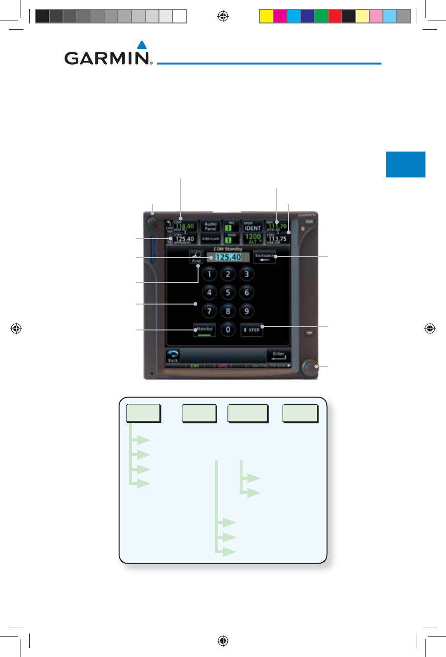
3-1190-01007-03 Rev. J
Garmin GTN 725/750 Pilot’s Guide
Foreword
Getting
Started
Audio &
Xpdr Ctrl
Com/Nav
FPL
Direct-To
Proc
Charts
Wpt Info
Map
Traffic
Terrain
Weather
Nearest
Services/
Music
Utilities
System
Messages
Symbols
Appendix
Index
3 NAV/COM (GTN 750 NAV/COM)
The GTN 750 features a digitally-tuned VHF Com radio and digitally-tuned
Nav/localizer and glideslope receivers. The GTN 750’s Com radio operates in the
aviation voice band, from 118.000 to 136.975 MHz, in 25 kHz steps (default).
For European operations, a Com radio configuration of 8.33 kHz steps is also
available.
Large and
Small Knobs
(Frequency
Adjust)
Volume and
Squelch
On/Off Knob
Active Com Frequency
Standby Com
Frequency
Active Nav Frequency
Standby Nav Frequency
Com Standby
Editing Window
Backspace
Key
Frequency
Monitor Key
Frequency
Transfer
(Flip/Flop)
Key
Find Frequency
Key
Numeric Keypad
Figure 3-1 Nav/Com Controls
Xfer
Recent
Nearest - Filter - Com - Nav
Flight Plan
User
Monitor Keypad
Find
Airport
VOR
Airport
FSS
ARTCC
Figure 3-2 Nav/Com Functional Diagram
190-01007-03-Final.indb 1 7/9/2015 2:06:58 PM
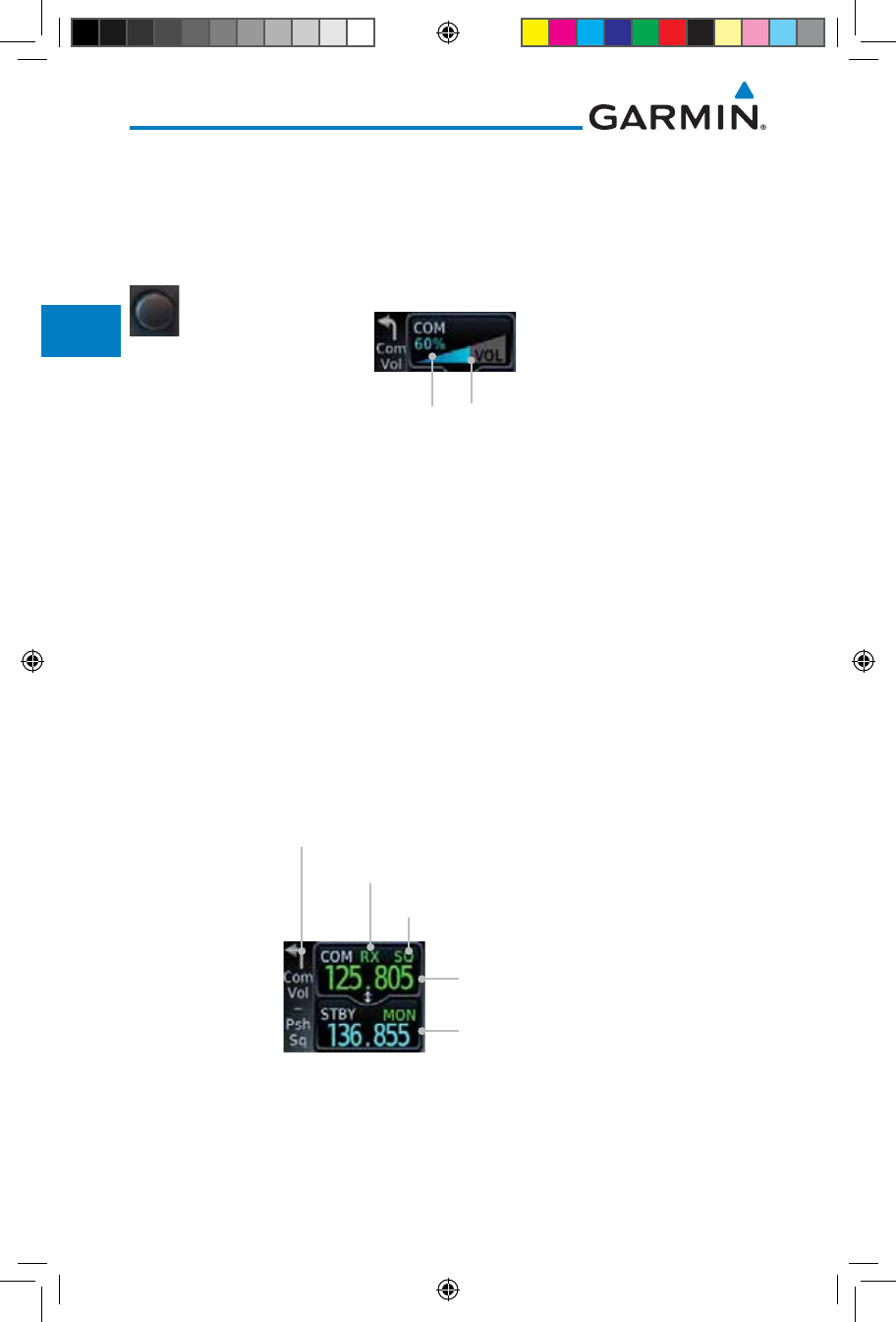
3-2
Garmin GTN 725/750 Pilot’s Guide
190-01007-03 Rev. J
Foreword
Getting
Started
Audio &
Xpdr Ctrl
Com/Nav
FPL
Direct-To
Proc
Charts
Wpt Info
Map
Traffic
Terrain
Weather
Nearest
Services/
Music
Utilities
System
Messages
Symbols
Appendix
Index
3.1 Volume
Com radio volume is adjusted using the Volume knob. Turn the Volume
knob clockwise to increase volume, or counterclockwise to decrease volume.
The level will be maintained until changed.
1. Turn the Volume knob to set the Com volume.
Percent Of Maximum Volume Graphic Scale Showing Volume
Figure 3-3 Com Volume Setting
2. A bar graph showing the relative volume level will indicate the
selected level and will disappear a few seconds after releasing
the Volume knob.
3.2 Squelch
The Com radio features an automatic squelch to reject many localized noise
sources. You may override the squelch function by pressing the Volume knob.
This facilitates listening to a distant station or setting the desired volume level.
To override the automatic squelch, press the Volume knob momentarily.
Press the Volume knob again to return to automatic squelch operation. A “SQ”
indication appears above the active Com frequency window in the upper left
corner of the display when automatic squelch is overridden.
Active Com Frequency
(Touch to Flip/Flop)
Standby Com Frequency
Squelch Annunciation
Com Control Text
Receive Annunciation
Figure 3-4 Com Controls
While receiving a transmission, an “RX” indication appears in the
Com
frequency
window to the immediate right of “
Com.
” A “TX” indication appears
at this location while you are transmitting.
190-01007-03-Final.indb 2 7/9/2015 2:06:59 PM
3-3190-01007-03 Rev. J
Garmin GTN 725/750 Pilot’s Guide
Foreword
Getting
Started
Audio &
Xpdr Ctrl
Com/Nav
FPL
Direct-To
Proc
Charts
Wpt Info
Map
Traffic
Terrain
Weather
Nearest
Services/
Music
Utilities
System
Messages
Symbols
Appendix
Index
3.3 Com Window and Tuning
Communication frequencies are selected by using the large and small right
knobs or by touching the value in the standby
Com
frequency field and using
the displayed keypad. The standby frequency always appears below the active
frequency. The active frequency is the frequency currently in use for transmit
and receive operations.
Once a frequency is selected in the standby field, it may be transferred to the
active frequency by touching the active frequency field.
NOTE: The Com window is normally active for adjustment, unless the NAV
window is made active by pressing the small right knob. The active state
automatically returns to the Com window after 30 seconds of inactivity.
To select a Com frequency using the small and large right knobs:
1. If the tuning cursor is not currently in the Com window,
press the small right knob momentarily. The Standby Com
frequency will be highlighted to indicate that it is active for
editing.
2. Turn the large right knob to select the desired megahertz
(MHz) value. For example, the “118” portion of the frequency
“118.30”.
3. Turn the small right knob to select the desired kilohertz
(kHz) value. For example, the “.30” portion of the frequency
“118.30”.
190-01007-03-Final.indb 3 7/9/2015 2:06:59 PM
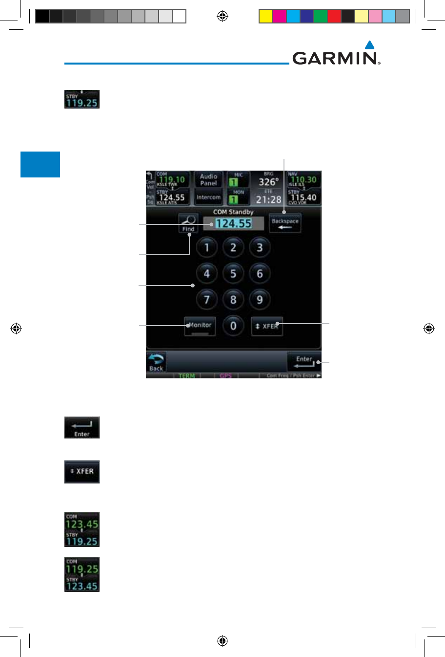
3-4
Garmin GTN 725/750 Pilot’s Guide
190-01007-03 Rev. J
Foreword
Getting
Started
Audio &
Xpdr Ctrl
Com/Nav
FPL
Direct-To
Proc
Charts
Wpt Info
Map
Traffic
Terrain
Weather
Nearest
Services/
Music
Utilities
System
Messages
Symbols
Appendix
Index
To select a Com frequency using the numeric keypad:
1. Touch the Standby window.
2. A pull down keypad will appear with the current Standby
frequency highlighted.
Com Standby
Editing Window
Backspace - Frequency
Clear Key
Frequency
Monitor Key
Frequency
Transfer
(Flip/Flop)
Key
Find Frequency
Key
Enter Key
Numeric Keypad
Figure 3-5 Com Standby Frequency Numeric Keypad
3. Touch the numeric keys to add the desired values and touch
Enter to accept the displayed value and place it into the
Standby Com window.
4. Touching the Xfer key will place the selected frequency directly
into the Active window.
To make the standby frequency the active frequency:
1. Touch the Com active frequency (top) window.
2. The Active (top) and Standby frequencies will flip/flop.
190-01007-03-Final.indb 4 7/9/2015 2:06:59 PM
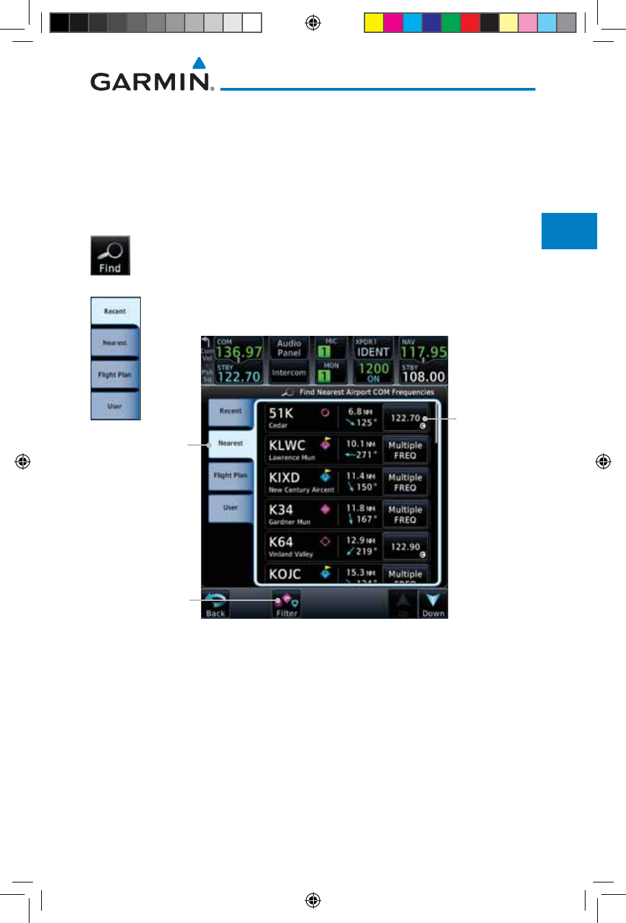
3-5190-01007-03 Rev. J
Garmin GTN 725/750 Pilot’s Guide
Foreword
Getting
Started
Audio &
Xpdr Ctrl
Com/Nav
FPL
Direct-To
Proc
Charts
Wpt Info
Map
Traffic
Terrain
Weather
Nearest
Services/
Music
Utilities
System
Messages
Symbols
Appendix
Index
3.3.1 Com Frequency Finding
The GTN 750’s frequency finding feature allows you to quickly select any
displayed database
Com
frequency as your standby frequency. The following are
some examples of selecting
Com
frequencies from some of the main GPS pages.
To select a Com frequency for a User created frequency, Recent selected
frequency, Nearest airport, or from your Flight Plan:
1. While viewing the numeric keypad touch the Find key.
Categories for User, Recent, Nearest, and Flight Plan are
available.
2. Touch Recent, Nearest, Flight Plan, or User.
Selected
Frequency
for Nearest
Airport
Selected
Frequency
Category
Touch to Select
Nearest List
Figure 3-6 Com Nearest Airport Frequency
3. Touch the desired Com frequency to select it and place it into
the Com Standby window.
190-01007-03-Final.indb 5 7/9/2015 2:06:59 PM
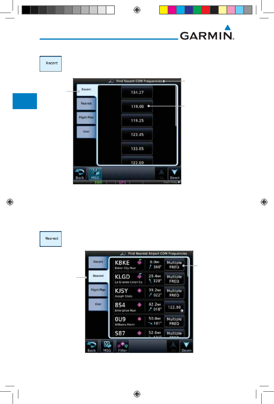
3-6
Garmin GTN 725/750 Pilot’s Guide
190-01007-03 Rev. J
Foreword
Getting
Started
Audio &
Xpdr Ctrl
Com/Nav
FPL
Direct-To
Proc
Charts
Wpt Info
Map
Traffic
Terrain
Weather
Nearest
Services/
Music
Utilities
System
Messages
Symbols
Appendix
Index
3.3.1.1 Find Recent Frequencies
1. While viewing the Find results, touch the Recent tab. A list
of the recently selected frequencies will be displayed.
Selected Frequency
Category
Touch Frequency From
Recent List To Select
Standby Frequency
Recent
Frequency
Category
Figure 3-7 Recent Com Frequency List
2. Touch the desired frequency to select it and place it into the
Standby window.
3.3.1.2 Find Nearest Frequencies
1. While viewing the Find results, touch the Nearest key. A list
of the nearest airport Com frequencies will be displayed.
Selected
Frequencies
For Nearest
Airport
Selected
Frequency
Category
Figure 3-8 Com Nearest Airport Frequency
190-01007-03-Final.indb 6 7/9/2015 2:06:59 PM
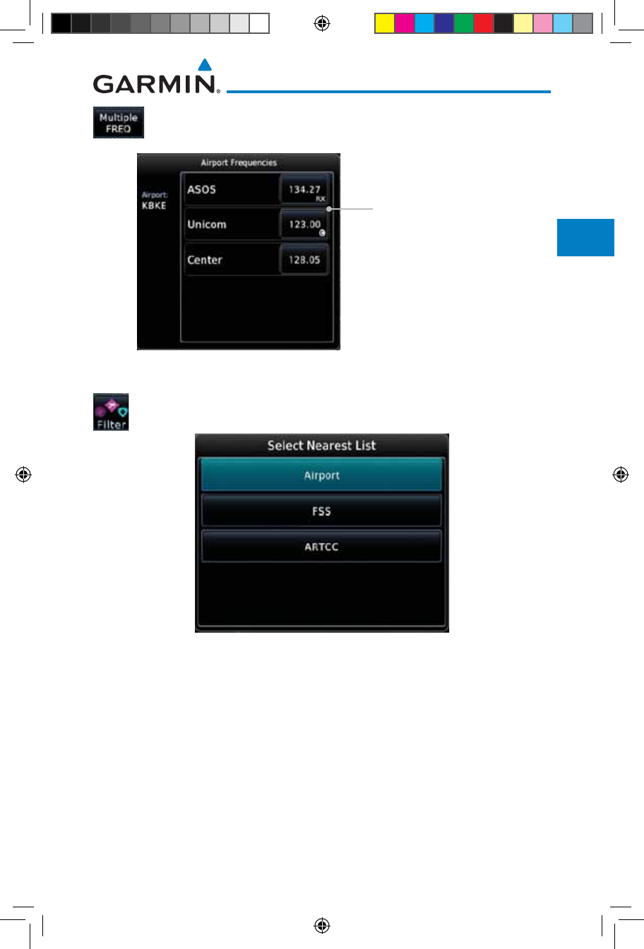
3-7190-01007-03 Rev. J
Garmin GTN 725/750 Pilot’s Guide
Foreword
Getting
Started
Audio &
Xpdr Ctrl
Com/Nav
FPL
Direct-To
Proc
Charts
Wpt Info
Map
Traffic
Terrain
Weather
Nearest
Services/
Music
Utilities
System
Messages
Symbols
Appendix
Index
2. Touch the Multiple FREQ key to show the available
frequencies.
Touch A Frequency Key
To Place It In The Standby
Window
Figure 3-9 Nearest Airport Multiple Frequency List
3. Touch the Filter key to filter the Nearest List by Airports, FSS,
or ARTCC.
Figure 3-10 Nearest Com Frequency List
4. Touch the desired Frequency List. Then, touch the desired
frequency to load it into the Standby window.
190-01007-03-Final.indb 7 7/9/2015 2:07:00 PM
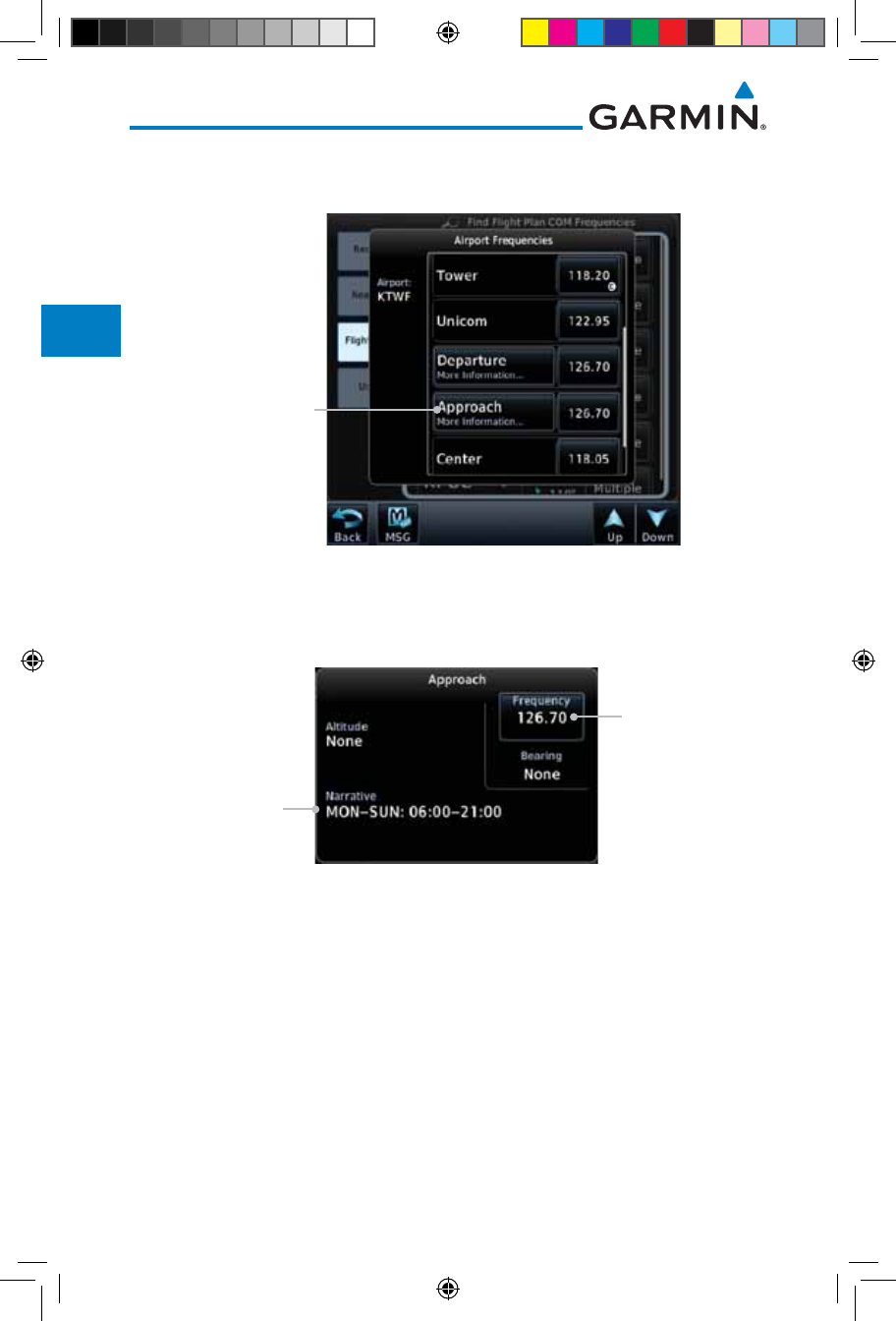
3-8
Garmin GTN 725/750 Pilot’s Guide
190-01007-03 Rev. J
Foreword
Getting
Started
Audio &
Xpdr Ctrl
Com/Nav
FPL
Direct-To
Proc
Charts
Wpt Info
Map
Traffic
Terrain
Weather
Nearest
Services/
Music
Utilities
System
Messages
Symbols
Appendix
Index
5. Some frequencies will have more information detail available.
Touch the key that shows "More Information."
Touch
For More
Information
Figure 3-11 More Information Is Available For Some Frequencies
6. More detailed information is shown on the display. Touch the
frequency key to load it into the Standby window.
Touch To Insert
Into Standby
Window
Additional
Information
Narrative
Figure 3-12 More Frequency Detail
190-01007-03-Final.indb 8 7/9/2015 2:07:00 PM
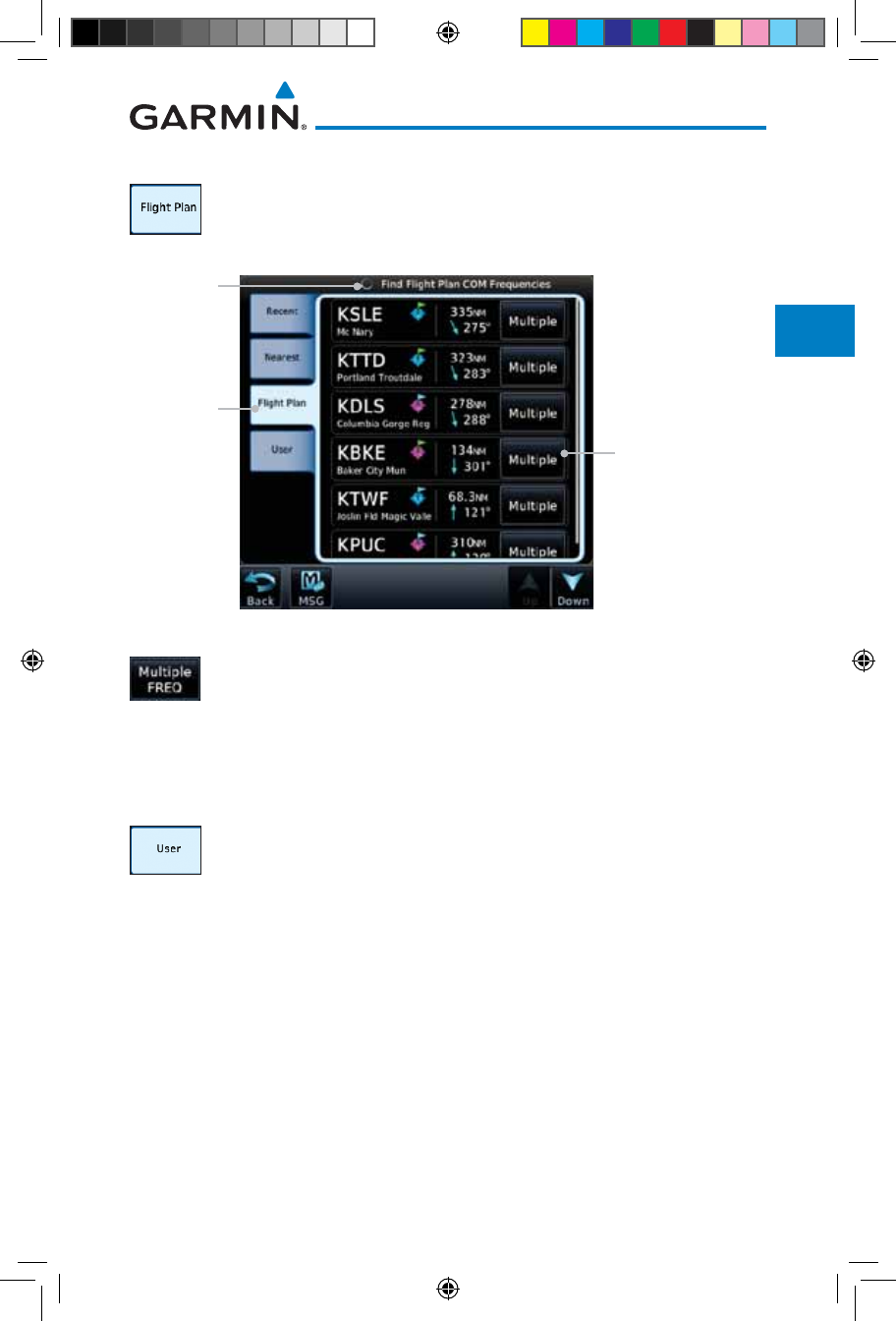
3-9190-01007-03 Rev. J
Garmin GTN 725/750 Pilot’s Guide
Foreword
Getting
Started
Audio &
Xpdr Ctrl
Com/Nav
FPL
Direct-To
Proc
Charts
Wpt Info
Map
Traffic
Terrain
Weather
Nearest
Services/
Music
Utilities
System
Messages
Symbols
Appendix
Index
3.3.1.3 Find Flight Plan Frequencies
1. While viewing the Find results, touch the Flight Plan tab.
A list of Com or Nav frequencies associated with the active
flight plan will be displayed.
Touch To Select
Frequency From List
For Nearest Airport
Selected
Frequency
Category
Selected
Frequency
Category
Figure 3-13 Flight Plan Frequency List
2. Touch the Multiple FREQ key to show the available
frequencies, if present.
3. Touch the desired frequency to select it and place it into the
Standby window.
3.3.1.4 Find User Frequencies
1. While viewing the Find results, touch the User tab. A list of
User-created frequencies will be displayed.
2. Touch the desired frequency to load it into the Standby window.
190-01007-03-Final.indb 9 7/9/2015 2:07:00 PM
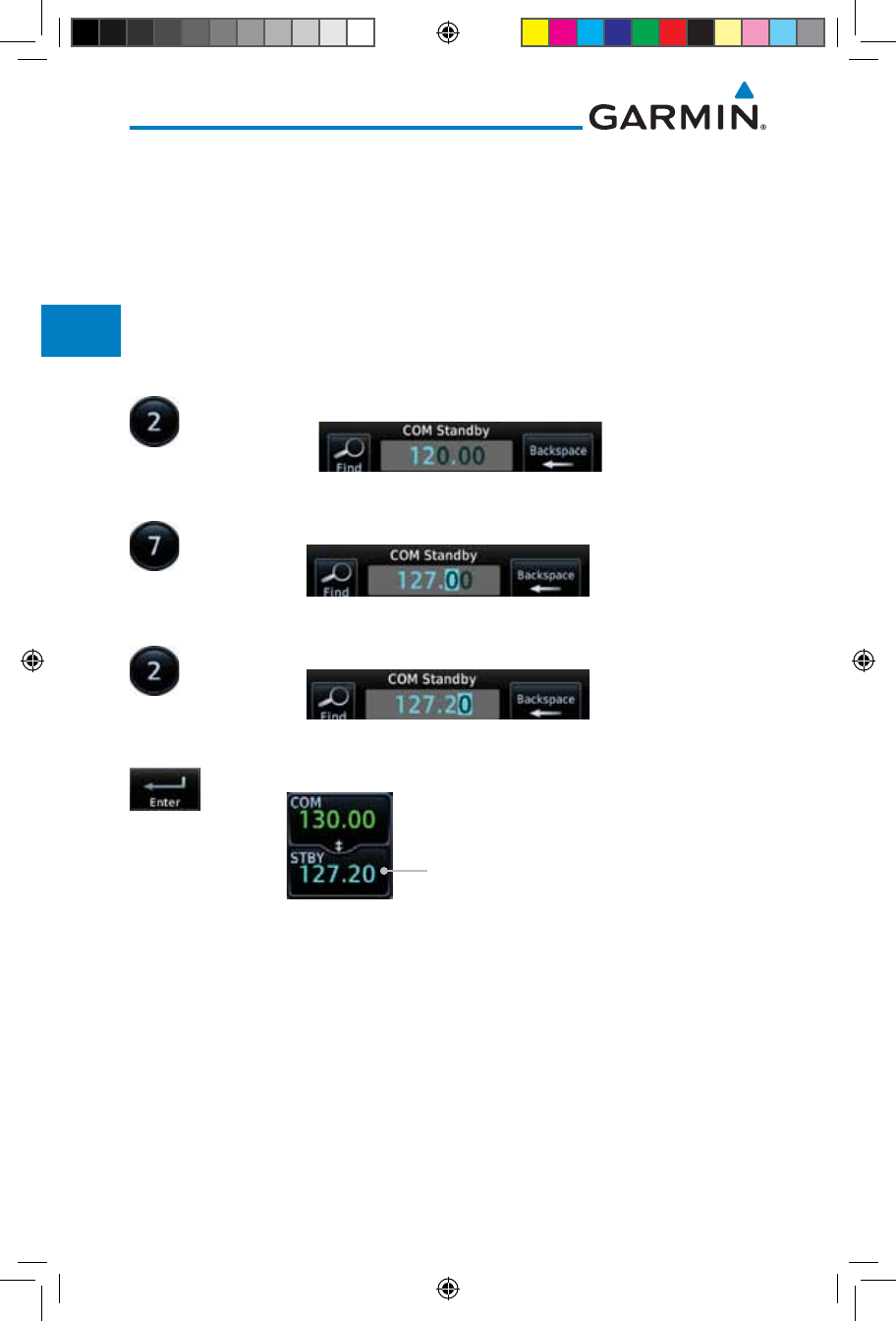
3-10
Garmin GTN 725/750 Pilot’s Guide
190-01007-03 Rev. J
Foreword
Getting
Started
Audio &
Xpdr Ctrl
Com/Nav
FPL
Direct-To
Proc
Charts
Wpt Info
Map
Traffic
Terrain
Weather
Nearest
Services/
Music
Utilities
System
Messages
Symbols
Appendix
Index
3.3.2 Simple Frequency Entry
Frequencies can be entered on the GTN without the leading one and/or
trailing zero(s). As a result, the pilot can touch “2”, “1”, and “5” for 121.50. If a
number is pressed that is not valid for the cursor location, the pilot is presented
with a confirmation pop-up upon selecting the typed frequency. Frequency
entry can be accomplished by typing every digit in the frequency or by leaving
off the leading one and/or trailing zero(s). The frequency that will be entered is
always displayed in the cursor window.
1. Touch the Standby frequency field and then touch the 2 key.
Figure 3-14 Simplified Frequency Entry Without Leading Number
2. Touch the 7 key.
Figure 3-15 Second Frequency Number
3. Touch the 2 key.
Figure 3-16 Final Frequency Without Trailing Number
4. Touch Enter.
Entered Frequency Value
Figure 3-17 Completed Frequency Entry
190-01007-03-Final.indb 10 7/9/2015 2:07:00 PM
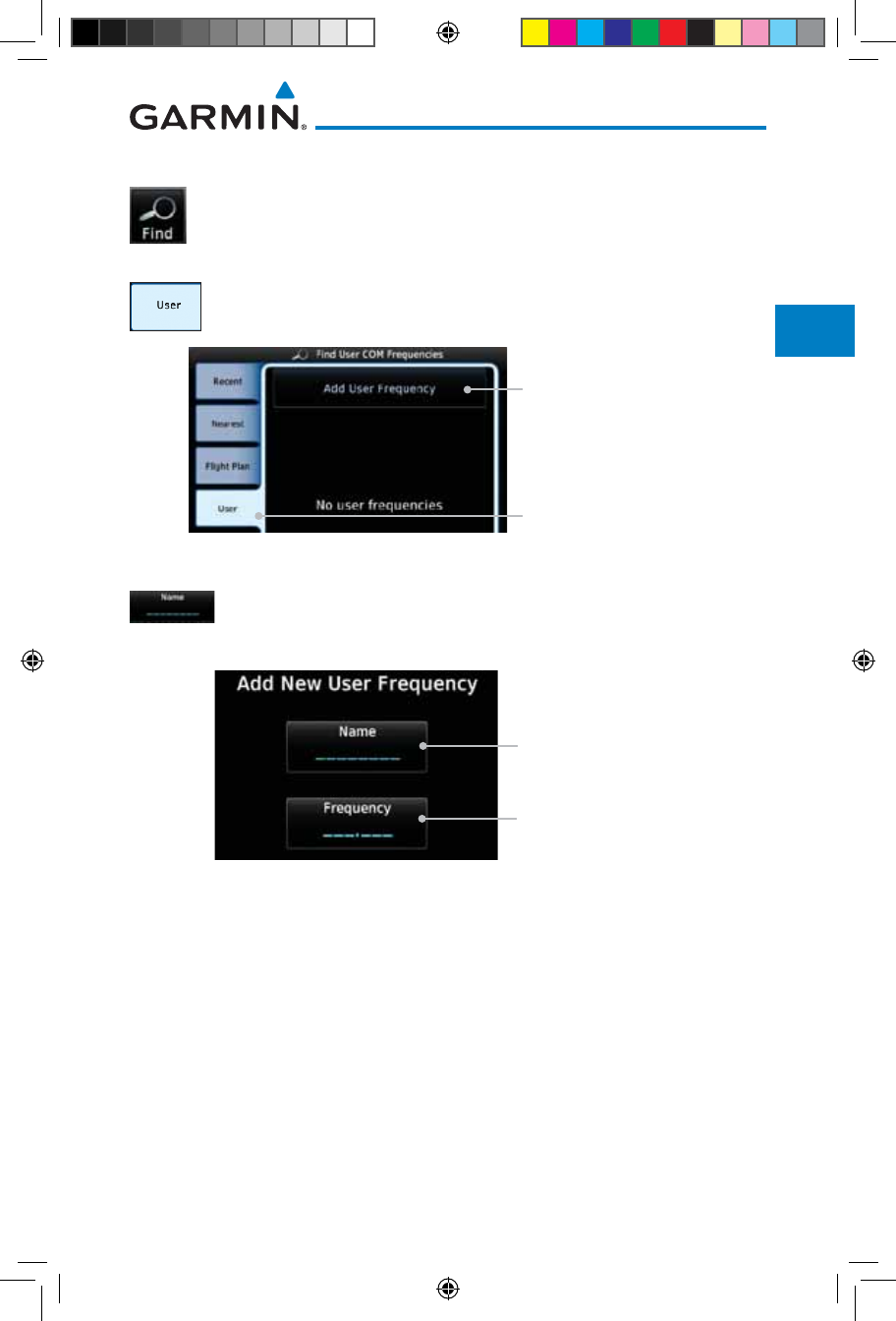
3-11190-01007-03 Rev. J
Garmin GTN 725/750 Pilot’s Guide
Foreword
Getting
Started
Audio &
Xpdr Ctrl
Com/Nav
FPL
Direct-To
Proc
Charts
Wpt Info
Map
Traffic
Terrain
Weather
Nearest
Services/
Music
Utilities
System
Messages
Symbols
Appendix
Index
3.3.3 Adding a New User Frequency
1. While viewing the numeric keypad touch the Find key at the
bottom of the display.
2. Touch the User tab and then touch the Add User Frequency
key.
Add User Frequency
User Frequency Selection
Figure 3-18 Add New User Frequency
3. The Add New User Frequency information window will now
be displayed. Touch the Name key to select a name for the
User frequency.
User Frequency Name
User Frequency Value
Figure 3-19 Add New User Frequency Detail Window
190-01007-03-Final.indb 11 7/9/2015 2:07:01 PM
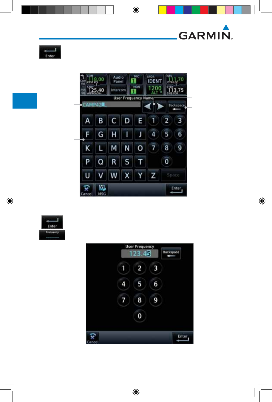
3-12
Garmin GTN 725/750 Pilot’s Guide
190-01007-03 Rev. J
Foreword
Getting
Started
Audio &
Xpdr Ctrl
Com/Nav
FPL
Direct-To
Proc
Charts
Wpt Info
Map
Traffic
Terrain
Weather
Nearest
Services/
Music
Utilities
System
Messages
Symbols
Appendix
Index
4. Select the characters from the alphanumeric keypad for the
desired name. Touch the Enter key to accept the displayed
Name.
User Frequency
Name
Alphanumeric
Keypad
Backspace
Cursor Movement
Figure 3-20 Select a Name for the New User Frequency
5. Touch the Frequency key and select the characters from
the keypad for the desired frequency. Touch the Enter key to
accept the displayed frequency.
Figure 3-21 Select a Frequency Value for the New User Frequency
190-01007-03-Final.indb 12 7/9/2015 2:07:01 PM
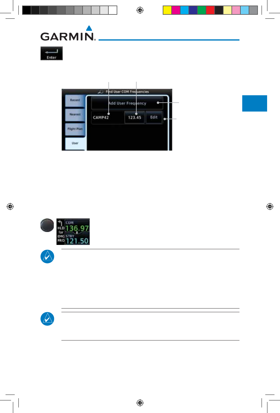
3-13190-01007-03 Rev. J
Garmin GTN 725/750 Pilot’s Guide
Foreword
Getting
Started
Audio &
Xpdr Ctrl
Com/Nav
FPL
Direct-To
Proc
Charts
Wpt Info
Map
Traffic
Terrain
Weather
Nearest
Services/
Music
Utilities
System
Messages
Symbols
Appendix
Index
6. Touch the Enter key to accept the displayed name and
frequency. The new User Frequency will be added to the list.
The list can store up to 15 user frequencies.
User Frequency Name User Frequency Value
Touch to Add Another
User Frequency
Touch to Edit/Remove
the User Frequency
Figure 3-22 Completed New User Frequency
3.3.4 Emergency Frequency
The GTN 750’s emergency frequency select provides a quick method
of selecting 121.50 MHz as the active frequency in the event of an in-flight
emergency. The emergency frequency select is available whenever the unit is on,
regardless of GPS or cursor status, or loss of the display.
To quickly tune and activate 121.50, press and hold volume
knob or the remote Com flip-flop key for approximately
two seconds.
NOTE: Pressing and holding the remote Com FLIP/FLOP key for
approximately two seconds, on units so configured, will lock the COM
board, preventing further changes in Com frequency until the Com board is
unlocked, by pressing the remote Com FLIP/FLOP key again for two seconds.
The following message will notify the pilot that the Com board has been
locked: “COM LOCKED TO 121.5 MHZ. HOLD REMOTE COM TRANSFER
KEY TO EXIT.”
NOTE: Under some circumstances if the Com system loses communication
with the main system, the radio will automatically tune to 121.50 MHz for
transmit and receive regardless of the displayed frequency.
190-01007-03-Final.indb 13 7/9/2015 2:07:01 PM
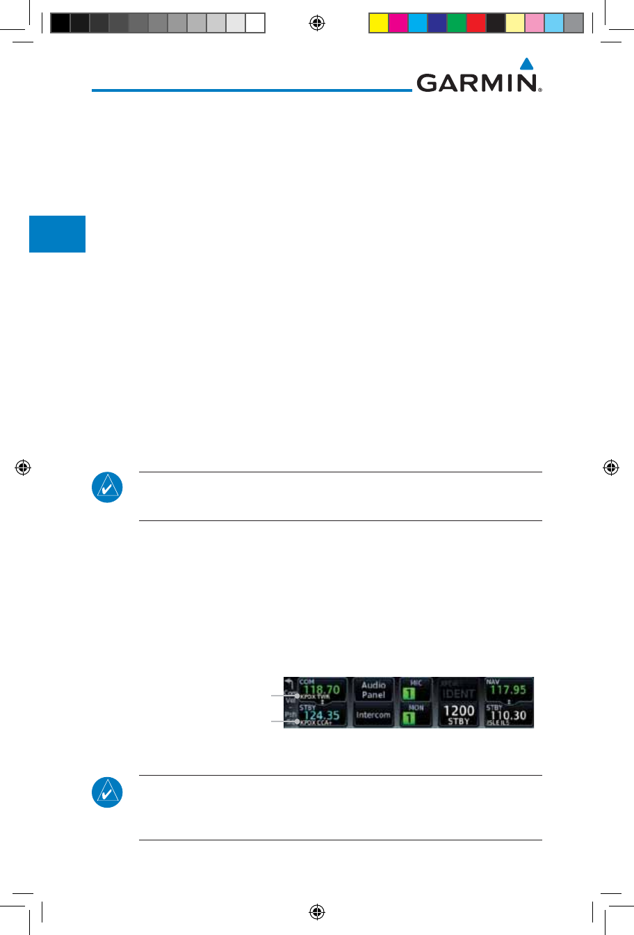
3-14
Garmin GTN 725/750 Pilot’s Guide
190-01007-03 Rev. J
Foreword
Getting
Started
Audio &
Xpdr Ctrl
Com/Nav
FPL
Direct-To
Proc
Charts
Wpt Info
Map
Traffic
Terrain
Weather
Nearest
Services/
Music
Utilities
System
Messages
Symbols
Appendix
Index
3.3.5 Stuck Microphone
Whenever the GTN 750 is transmitting, a “TX” indication appears in the
Com
window. If the push-to-talk key on the microphone is stuck or accidentally
left in the keyed position, or continues to transmit after the key is released,
the
Com
transmitter automatically times out (or ceases to transmit) after 30
seconds of continuous broadcasting. You will also receive a “
Com
push-to-talk
key stuck” message as long as the stuck condition exists.
3.3.6 Remote Frequency Selection Control
On units configured for remote Com frequency Recall, pressing the remote
recall switch will load the next preset Com frequency into the unit’s Standby
frequency box. The remote recall switch can be pressed multiple times to scroll
the entire preset frequency list through the Standby frequency box (the list will
“wrap” from the bottom of the list back up to the top, skipping any empty preset
positions).
The standby frequency isn’t activated until a Com FLIP/FLOP switch (either
bezel-mounted or remote (COM RMT XFR) is pressed. Remote Frequency Selection
only functions on units configured for a remote Com Frequency recall switch.
NOTE: For software prior to version 5.00, frequencies must be stored in
the User Frequency List prior to utilizing the remote channel select switch.
3.3.7 Reverse Frequency Look-Up
When the Reverse Frequency Look-Up feature is enabled in System-Setup,
the identifier and frequency type will be shown for the selected Com and Nav
frequencies for the nearest stations that are in the aviation database when the
unit is receiving a valid position input. Station Identifiers with a “+” sign will
have more stations associated with this frequency than just the type displayed.
The “+” Sign Indicates More
Stations Associated With This
Frequency
Identifier and Type Shown
for the Selected Frequency
Figure 3-23 Reverse Frequency Look-Up
NOTE: It can take up to 2 minutes for the RFL frequency to change after
crossing the half way point when flying from one airport to another that
both use the same frequency.
190-01007-03-Final.indb 14 7/9/2015 2:07:01 PM
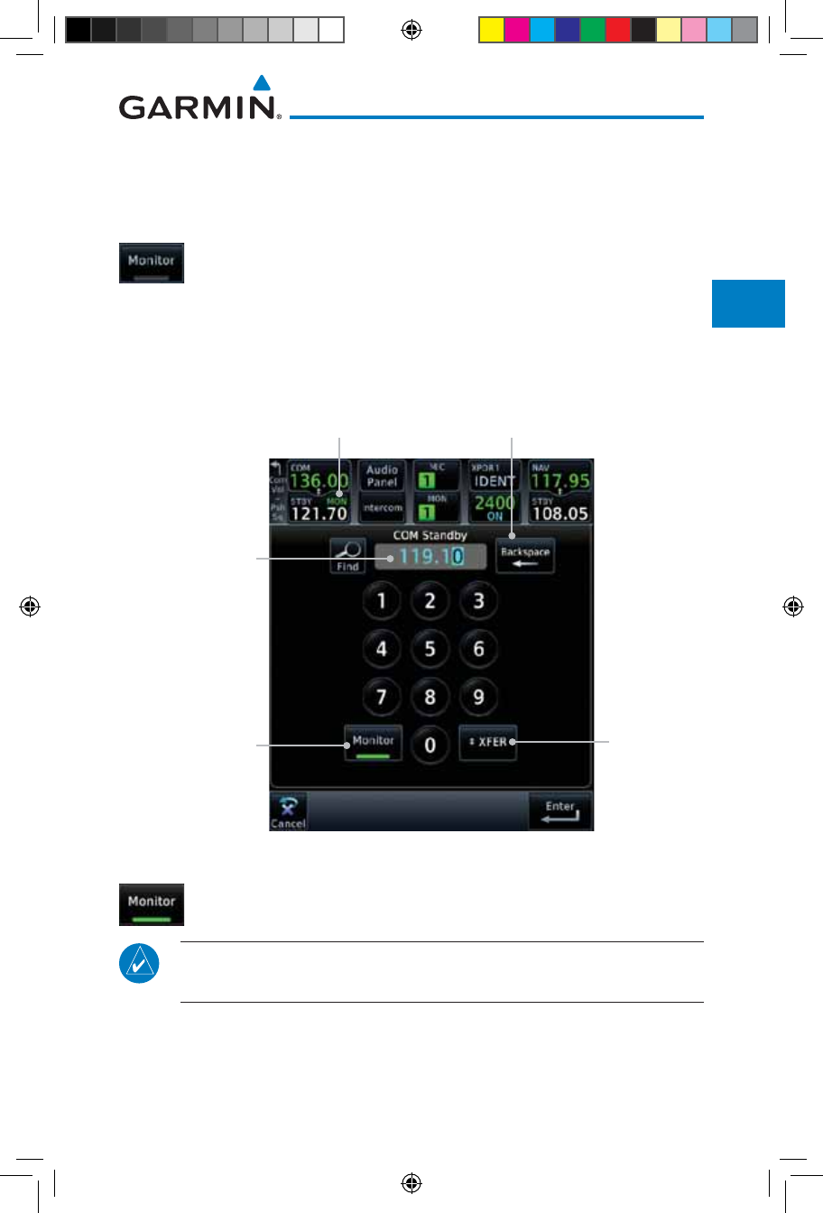
3-15190-01007-03 Rev. J
Garmin GTN 725/750 Pilot’s Guide
Foreword
Getting
Started
Audio &
Xpdr Ctrl
Com/Nav
FPL
Direct-To
Proc
Charts
Wpt Info
Map
Traffic
Terrain
Weather
Nearest
Services/
Music
Utilities
System
Messages
Symbols
Appendix
Index
3.4 Com Frequency Monitoring
The Frequency Monitoring function allows you to listen to the Standby
frequency in the Com radio, while monitoring the Active frequency for activity.
1. Touch the Monitor key to listen to the standby frequency.
A small “MON” annunciation is displayed to the right of the
Standby frequency. A green bar will show on the Monitor
key. When the Active frequency receives a signal, the unit will
switch automatically to the Active frequency and then switch
back to the standby frequency when activity ceases.
Com Standby
Editing Window
Frequency Monitor
Annunciation
Standby Frequency
Clear Key
Frequency
Monitor Key
Frequency
Transfer
(Flip-Flop)
Key
Figure 3-24 Com Frequency Monitoring
2. The Monitor function is deactivated when you touch the
Monitor key again and the green bar is extinguished.
NOTE: The Com radio Monitoring function is different than the Monitor
function of the Audio Panel.
190-01007-03-Final.indb 15 7/9/2015 2:07:01 PM
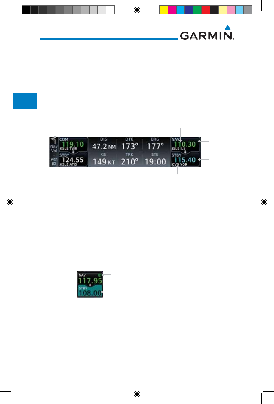
3-16
Garmin GTN 725/750 Pilot’s Guide
190-01007-03 Rev. J
Foreword
Getting
Started
Audio &
Xpdr Ctrl
Com/Nav
FPL
Direct-To
Proc
Charts
Wpt Info
Map
Traffic
Terrain
Weather
Nearest
Services/
Music
Utilities
System
Messages
Symbols
Appendix
Index
3.5 NAV (VOR/Localizer/Glideslope) Receiver
Operations
The GTN 750 includes digitally-tuned Nav/localizer and glideslope receivers
with the desired frequency selected on the Nav window, along the top right-hand
side of the display. Frequency selection is performed by pressing the small right
knob to activate Nav Standby frequency editing and then turning the small and
large right knobs or keypad to select the desired frequency.
Nav Control Text Active Nav
Frequency
Standby Nav
Frequency
Touch To
Flip/Flop
NAV / STBY
Touch To
Edit STBY
Figure 3-25 Nav Frequency Window
3.5.1 Ident Audio and Volume
Nav ident is enabled by pressing the Volume knob when the Nav window is
active. When Nav ident is enabled, the ID annunciation will appear in the active
Nav window and Morse code tones will be heard. When the Nav function is
enabled, the Nav Standby channel window will highlight briefly and then turn
to blue text. The Nav Standby frequency will be active for editing for about 30
seconds before the Com Standby frequency becomes active for editing.
Nav Standby Frequency Highlighted To
Indicate It Is Active for Frequency Selection
Nav Ident Is Active
Figure 3-26 Nav Standby Frequency Window and Ident is Active
Nav audio volume is adjusted using the Volume knob. Turn the Volume
knob clockwise to increase volume, or counterclockwise to decrease volume.
190-01007-03-Final.indb 16 7/9/2015 2:07:02 PM
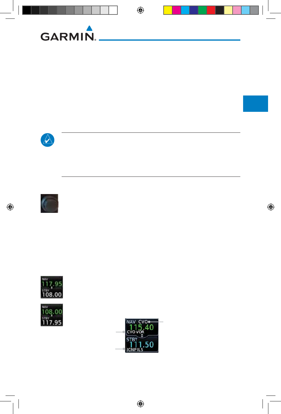
3-17190-01007-03 Rev. J
Garmin GTN 725/750 Pilot’s Guide
Foreword
Getting
Started
Audio &
Xpdr Ctrl
Com/Nav
FPL
Direct-To
Proc
Charts
Wpt Info
Map
Traffic
Terrain
Weather
Nearest
Services/
Music
Utilities
System
Messages
Symbols
Appendix
Index
3.5.2 Nav Tuning Window
Nav frequencies are selected with the tuning cursor in the standby Nav
frequency field, and using the small and large right knobs to dial in the desired
frequency. The keypad may also be used for frequency entry after touching
the Standby window. The standby frequency always appears below the active
frequency. The active frequency is the frequency currently in use. The GTN will
automatically decode Morse code and display the Ident for the active frequency
above it. The RFL (reverse frequency lookup) Identifier is displayed below the
frequency and is only dependent on GPS position and database information.
NOTE: Tuning is normally active in the Com window, unless placed in the
Nav window by pressing the small right knob. When the tuning cursor is
in the Nav window, it automatically returns to the Com window after 30
seconds of inactivity. The active frequency in either window cannot be
accessed directly — only the standby frequency is active for editing.
To select a VOR/localizer/ILS frequency:
1. Touch the small right knob momentarily to make the Nav
Standby frequency value active for editing. The window will
be highlighted momentarily.
2. Turn the large right knob to select the desired megaHertz
(MHz) value. For example, the “117” portion of the frequency
“117.80”.
3. Turn the small right knob to select the desired kiloHertz
(kHz) value. For example, the “.80” portion of the frequency
“117.80”.
4. Touch the Nav active (top) frequency to make the standby
frequency.
5. The Active (top) and Standby frequencies will switch.
Nav Frequencies In The Database
Will Display The Ident Based on
GPS Position
Nav Frequencies Will
Automatically Decode Morse
Code And Display The Ident
Figure 3-27 Automatic Nav Frequency Ident Decoding
190-01007-03-Final.indb 17 7/9/2015 2:07:02 PM
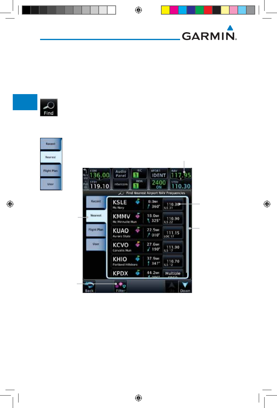
3-18
Garmin GTN 725/750 Pilot’s Guide
190-01007-03 Rev. J
Foreword
Getting
Started
Audio &
Xpdr Ctrl
Com/Nav
FPL
Direct-To
Proc
Charts
Wpt Info
Map
Traffic
Terrain
Weather
Nearest
Services/
Music
Utilities
System
Messages
Symbols
Appendix
Index
3.5.3 Nav Frequency Finding
The GTN 750’s frequency finding feature allows you to quickly select any
displayed database Nav frequency as your standby frequency.
To select a Nav frequency for a User created frequency, Recent selected
frequency, Nearest airport, or from your Flight Plan:
1. While viewing the numeric keypad touch the Find key at the
bottom of the display. Categories for User, Recent, Nearest,
and Flight Plan are available.
2. Touch the User, Recent, Nearest, or Flight Plan key.
Active Nav
Frequency Key
Nearest Nav
Frequency List
Touch To
Select For
Standby Nav
Frequency
Nearest Nav
Frequency List Is
Selected
Touch to Filter
Nearest List
Figure 3-28 Nearest Airport Nav Frequency
190-01007-03-Final.indb 18 7/9/2015 2:07:02 PM
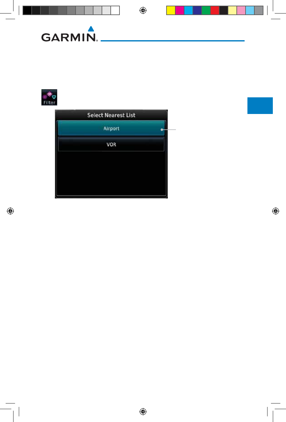
3-19190-01007-03 Rev. J
Garmin GTN 725/750 Pilot’s Guide
Foreword
Getting
Started
Audio &
Xpdr Ctrl
Com/Nav
FPL
Direct-To
Proc
Charts
Wpt Info
Map
Traffic
Terrain
Weather
Nearest
Services/
Music
Utilities
System
Messages
Symbols
Appendix
Index
3. Touch the desired Nav frequency to select it and place it into
the Nav Standby window.
OR
4. Touch the Filter key to narrow the list by category, such as
Airport and VOR, and then select a given frequency.
Touch To Select Nearest
Frequency List Type
Figure 3-29 Nearest Nav Frequency List
190-01007-03-Final.indb 19 7/9/2015 2:07:02 PM

3-20
Garmin GTN 725/750 Pilot’s Guide
190-01007-03 Rev. J
Foreword
Getting
Started
Audio &
Xpdr Ctrl
Com/Nav
FPL
Direct-To
Proc
Charts
Wpt Info
Map
Traffic
Terrain
Weather
Nearest
Services/
Music
Utilities
System
Messages
Symbols
Appendix
Index
This page intentionally left blank
190-01007-03-Final.indb 20 7/9/2015 2:07:02 PM
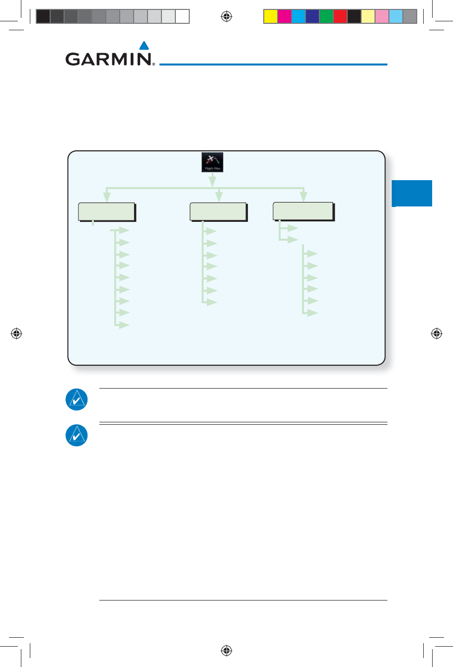
4-1190-01007-03 Rev. J
Garmin GTN 725/750 Pilot’s Guide
Foreword
Getting
Started
Audio &
Xpdr Ctrl
Com/Nav
FPL
Direct-To
Proc
Charts
Wpt Info
Map
Traffic
Terrain
Weather
Nearest
Services/
Music
Utilities
System
Messages
Symbols
Appendix
Index
4 FLIGHT PLANS
The GTN 7XX lets you create up to 99 different flight plans, with up to 100
waypoints in each flight plan. The Flight Plan function is accessed by touching
the Flight Plan key on the Home page. The Flight Plan function allows you to
create, store, edit, and copy flight plans.
Menu
Catalog
Store
Delete
Preview
Parallel Track
Invert
Edit Data Fields
* "Load SAR" is only shown when the Search and Rescue feature is enabled by the installer
** "Load Procedures" is shown for airports
***"Load Airway" is shown for waypoints on a published airway
Active FPL
Activate Leg
Insert Before
Insert After
Load SAR*
Hold at Waypoint
Load Procedures**
Load Airway***
Waypoint Info
Remove
Waypoint
Options
Add Waypoint
Recent
Nearest
Flight Plan
User
Search by Name
Search by City
Select Waypoint
Find
Figure 4-1 Flight Plan Functional Diagram
NOTE: Navigation is provided for fixed wing aircraft above 30 kts and for
rotorcraft above 10 kts.
NOTE: The Chart feature provides a digital representation of a paper
chart and provides no vertical or lateral course guidance. Flight Plan and
Procedures are separate from Charts, and do provide vertical and lateral
course guidance for the loaded route or procedure shown on the Flight
Plan page. The term “Chart Unavailable” means that the chart cannot be
viewed on the Charts due to either a chart not being published, or an error
in the Chart database, but does not preclude its availability or inclusion of
the procedure in the Flight Plan or Procedures portion of the system. The
absence of a chart for a particular Departure, Arrival, or Approach does
not preclude its availability or inclusion in the Flight Plan or Procedures
portion of the system. The absence of a particular Departure, Arrival, or
Approach under the Flight Plan or Procedures portion of the system does
not preclude the ability to view the Chart for that procedure under the
Chart feature.
190-01007-03-Final.indb 1 7/9/2015 2:07:02 PM
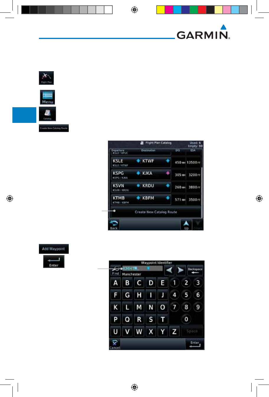
4-2
Garmin GTN 725/750 Pilot’s Guide
190-01007-03 Rev. J
Foreword
Getting
Started
Audio &
Xpdr Ctrl
Com/Nav
FPL
Direct-To
Proc
Charts
Wpt Info
Map
Traffic
Terrain
Weather
Nearest
Services/
Music
Utilities
System
Messages
Symbols
Appendix
Index
4.1 Creating a New Flight Plan
4.1.1 Creating a New Flight Plan in the Catalog
1. From the Home page, touch Flight Plan.
2. Touch Menu and then the Catalog key.
3. Touch the Create New Catalog Route key at the end of
the flight plan list in the Catalog.
Touch To Create
New Flight Plan
Figure 4-2 Create a New Catalog Route (Flight Plan)
4. Touch the Add Waypoint key and select a waypoint identifier
with the alphanumeric keypad. Then, touch Enter.
Selected Flight
Plan Waypoint
Figure 4-3 Select a Waypoint for the New Flight Plan
190-01007-03-Final.indb 2 7/9/2015 2:07:03 PM
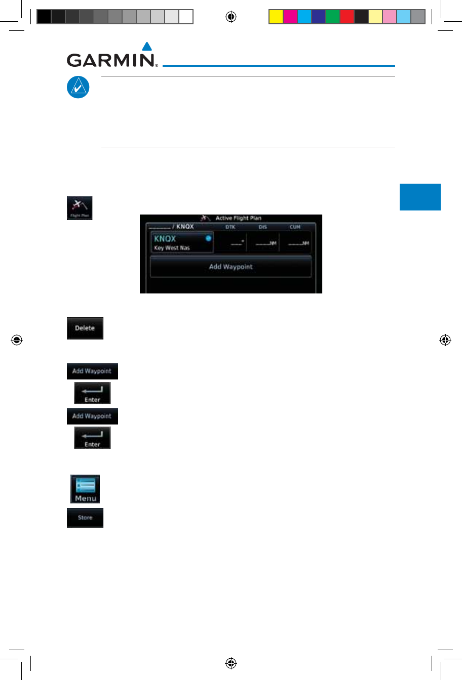
4-3190-01007-03 Rev. J
Garmin GTN 725/750 Pilot’s Guide
Foreword
Getting
Started
Audio &
Xpdr Ctrl
Com/Nav
FPL
Direct-To
Proc
Charts
Wpt Info
Map
Traffic
Terrain
Weather
Nearest
Services/
Music
Utilities
System
Messages
Symbols
Appendix
Index
NOTE: If a flight plan that includes a procedure that has been modified
by the pilot is saved into the flight plan catalog, the GTN cannot check the
accuracy of that procedure when that flight plan is used on a later flight. It
is recommended that flight plans with modified procedures not be saved
in the flight plan catalog.
4.1.2 Creating a New Flight Plan from the Active
Flight Plan
1. From the Home page, touch Flight Plan.
Figure 4-4 Create New Flight Plan by Clearing Active Flight Plan
2. If there is already an Active Flight Plan, touch Menu and then
the Delete and OK keys to delete the existing active flight
plan. The stored flight plan in the Catalog will not be deleted.
3. Touch the Add Waypoint key and select a waypoint identifier
with the alphanumeric keypad. Then, touch Enter.
4. Touch the Add Waypoint key and select the waypoint identifier
with the keypad for the next waypoint. Touch Enter.
5. Continue adding waypoints as needed.
6. Touch Menu and then touch Store to store the flight plan
in the Catalog. The screen will now display the Flight Plan
Catalog and show the new flight plan. Flight plans are listed
by the Departure and Destination waypoints.
190-01007-03-Final.indb 3 7/9/2015 2:07:03 PM
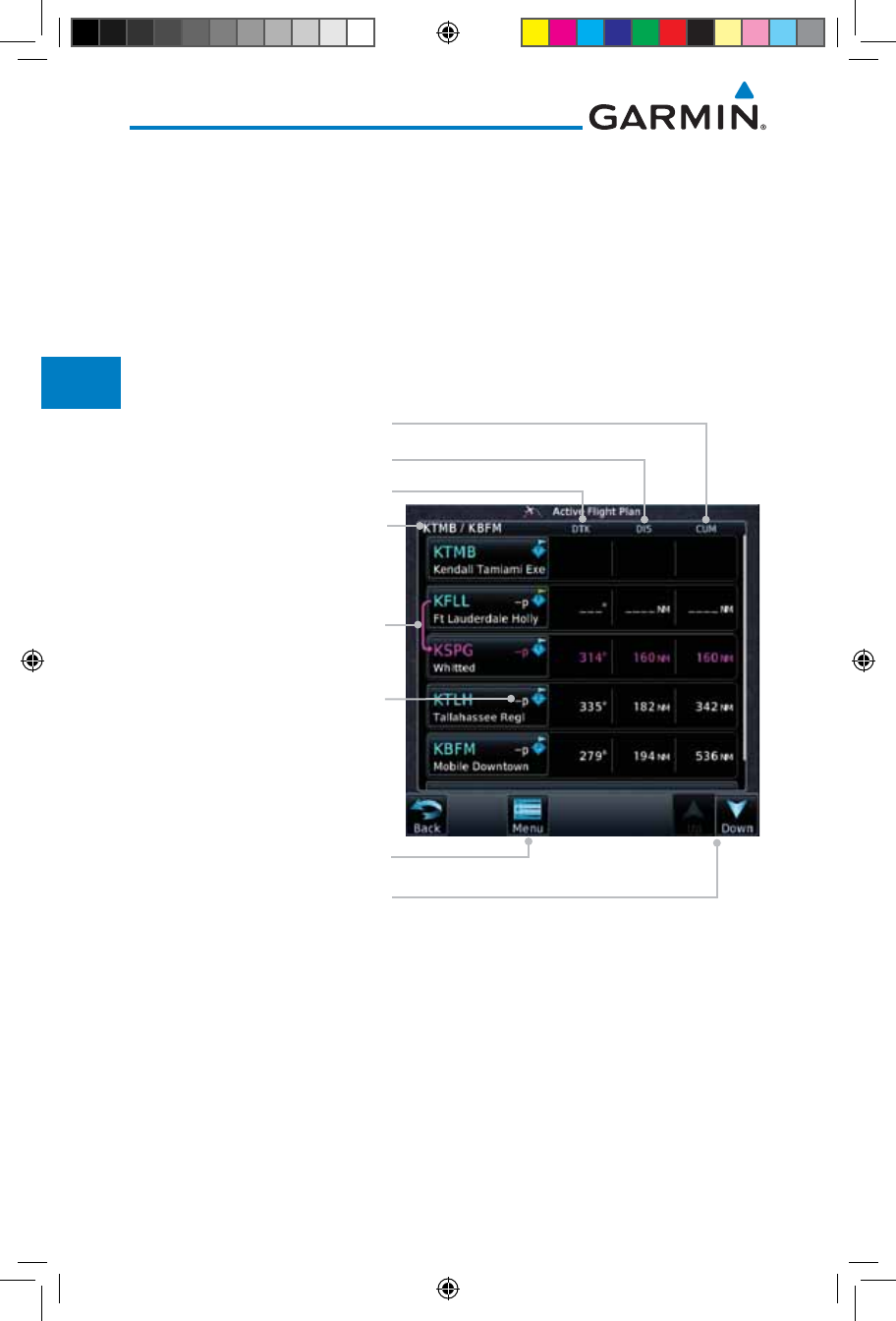
4-4
Garmin GTN 725/750 Pilot’s Guide
190-01007-03 Rev. J
Foreword
Getting
Started
Audio &
Xpdr Ctrl
Com/Nav
FPL
Direct-To
Proc
Charts
Wpt Info
Map
Traffic
Terrain
Weather
Nearest
Services/
Music
Utilities
System
Messages
Symbols
Appendix
Index
4.2 Active Flight Plan Page
The Active Flight Plan Page provides information and editing functions for
the flight plan currently in use for navigation. Once you have activated a flight
plan, the Active Flight Plan Page shows each waypoint for the flight plan, along
with the Desired Track (DTK), Distance (DIST) for each leg and Cumulative
Distance (CUM). The data fields are user-selectable and may be changed to
display Cumulative Distance (CUM), Distance (DIST), Desired Track (DTK), En
Route Safe Altitude (ESA), or Estimated Time of Arrival (ETA).
Origin and Destination Waypoints
Active Leg Navigation
Flight Plan Menu Options
Up/Down Keys to Scroll FPL
Parallel Track Active
DTK Between Legs *
DIST Between Legs *
Cumulative Dist Between
Current Position and Next Wpt *
Figure 4-5 Active Flight Plan Page
* The field types may be changed using the Edit Fields function in the Flight
Plan page Menu.
190-01007-03-Final.indb 4 7/9/2015 2:07:03 PM
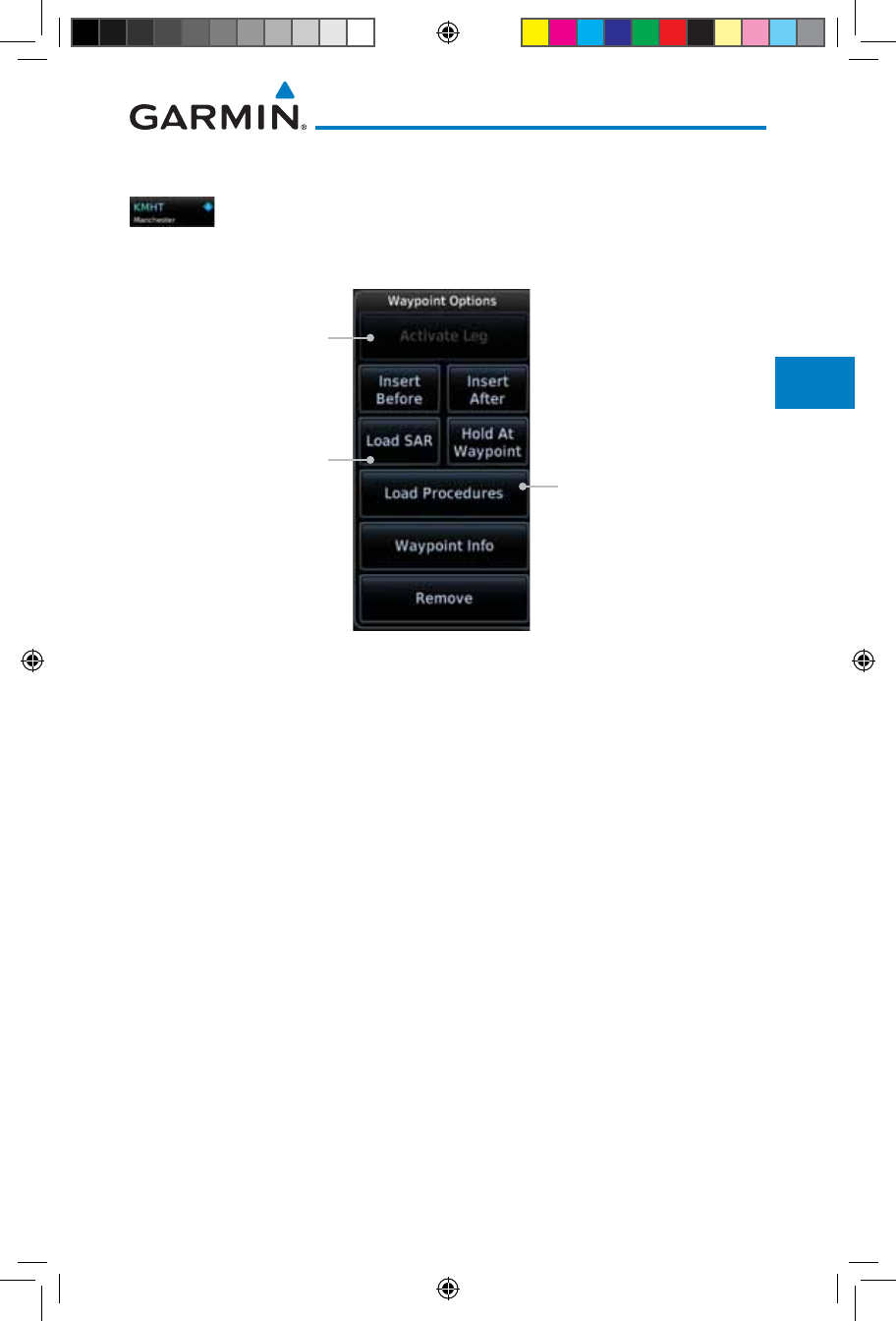
4-5190-01007-03 Rev. J
Garmin GTN 725/750 Pilot’s Guide
Foreword
Getting
Started
Audio &
Xpdr Ctrl
Com/Nav
FPL
Direct-To
Proc
Charts
Wpt Info
Map
Traffic
Terrain
Weather
Nearest
Services/
Music
Utilities
System
Messages
Symbols
Appendix
Index
4.2.1 Waypoint Options
1. While viewing the Active Flight Plan page, touch the desired
flight plan waypoint. The Waypoint Options window will be
shown.
Touch Key To
Select Option Waypoint Options List
Greyed Options
Are Not Available
Figure 4-6 Active Flight Plan Wpt Options with SAR Available
2. Touch one of the options to perform the selected action. Cancel
the option selection by touching the Back key.
190-01007-03-Final.indb 5 7/9/2015 2:07:03 PM
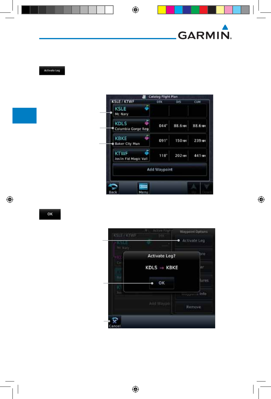
4-6
Garmin GTN 725/750 Pilot’s Guide
190-01007-03 Rev. J
Foreword
Getting
Started
Audio &
Xpdr Ctrl
Com/Nav
FPL
Direct-To
Proc
Charts
Wpt Info
Map
Traffic
Terrain
Weather
Nearest
Services/
Music
Utilities
System
Messages
Symbols
Appendix
Index
4.2.1.1 Activate Leg
The Activate Leg option allows you to change the active leg of a flight plan.
1. On the Waypoint Options menu, touch the desired TO waypoint
and then the Activate Leg key to select the TO waypoint as
the active leg for navigation.
Touch to Select As
New TO Wpt and
To Activate Leg
Current Leg
Current TO Wpt
Figure 4-7 Active Flight Plan Activate Leg Option
2. Touch the OK key to set the selected leg as the Active Leg, or
Cancel to not select it.
Touch OK To
Activate Leg
Activate Leg Option
Was Selected
Touch Cancel To
Cancel The Operation
And Return To the
Flight Plan View
Figure 4-8 Active Flight Plan Activate Leg Option
190-01007-03-Final.indb 6 7/9/2015 2:07:03 PM
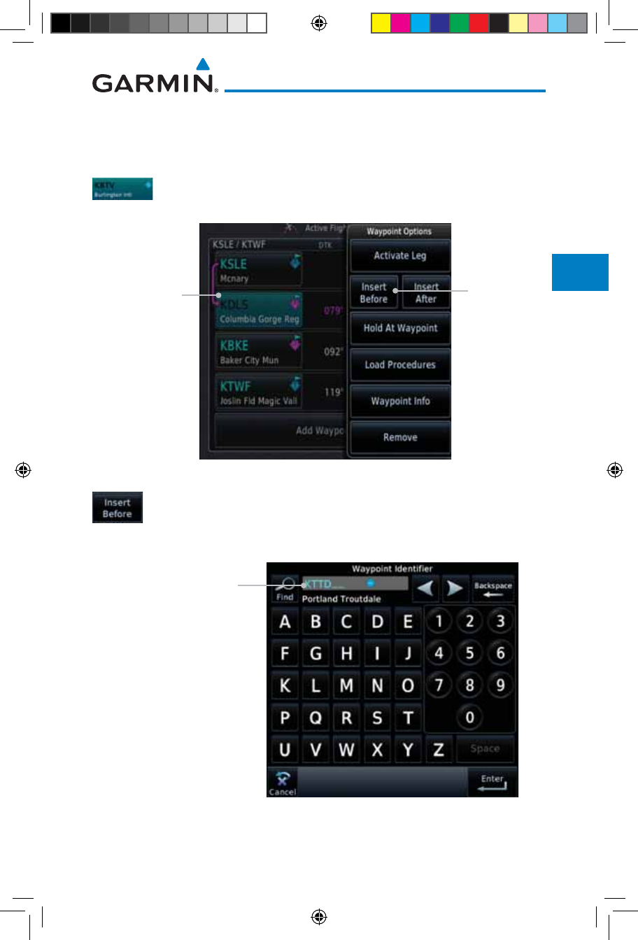
4-7190-01007-03 Rev. J
Garmin GTN 725/750 Pilot’s Guide
Foreword
Getting
Started
Audio &
Xpdr Ctrl
Com/Nav
FPL
Direct-To
Proc
Charts
Wpt Info
Map
Traffic
Terrain
Weather
Nearest
Services/
Music
Utilities
System
Messages
Symbols
Appendix
Index
4.2.1.2 Insert Before
The Insert Before option allows you to insert a new waypoint into the active
flight plan before the selected waypoint.
1. On the Active Flight Plan page, touch the desired waypoint in
the flight plan. The Waypoint Options list will be displayed.
Insert Before
Option Was
Selected
Option Will
Insert New
Waypoint
Before This
Selected Flight
Plan Waypoint
Figure 4-9 Active Flight Plan Insert Waypoint Before Option
2. Touch the Insert Before key to select a new waypoint before
the selected waypoint.
3. Select a waypoint identifier with the alphanumeric keypad.
Choose New Waypoint
To "Insert Before" The
Selected Flight Plan
Waypoint
Figure 4-10 Use the Alphanumeric Keypad to Select Waypoint to Insert Before
190-01007-03-Final.indb 7 7/9/2015 2:07:04 PM
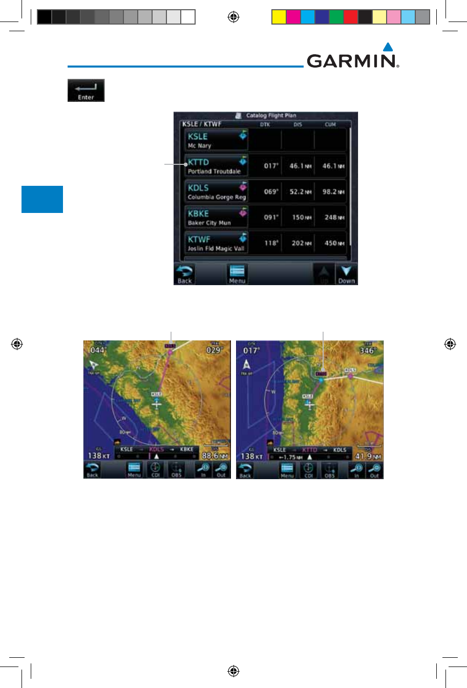
4-8
Garmin GTN 725/750 Pilot’s Guide
190-01007-03 Rev. J
Foreword
Getting
Started
Audio &
Xpdr Ctrl
Com/Nav
FPL
Direct-To
Proc
Charts
Wpt Info
Map
Traffic
Terrain
Weather
Nearest
Services/
Music
Utilities
System
Messages
Symbols
Appendix
Index
4. Then, touch Enter to confirm the selection, or touch Cancel
to cancel any changes. The new flight plan will be shown.
New
Waypoint
Inserted
Before The
Selected Flight
Plan Waypoint
Figure 4-11 New Waypoint Is Inserted Before the Selected Waypoint
Selected Flight
Plan Waypoint
New Flight
Plan Waypoint
Figure 4-12 Flight Plan Before and After New Waypoint Inserted
190-01007-03-Final.indb 8 7/9/2015 2:07:04 PM
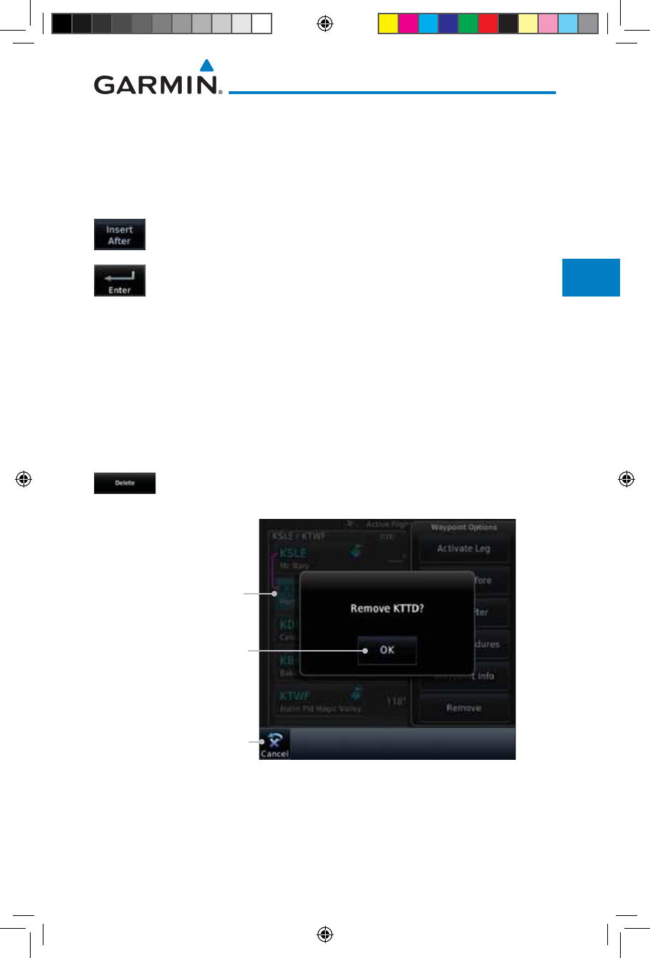
4-9190-01007-03 Rev. J
Garmin GTN 725/750 Pilot’s Guide
Foreword
Getting
Started
Audio &
Xpdr Ctrl
Com/Nav
FPL
Direct-To
Proc
Charts
Wpt Info
Map
Traffic
Terrain
Weather
Nearest
Services/
Music
Utilities
System
Messages
Symbols
Appendix
Index
4.2.1.3 Insert After
The Insert After option allows you to insert a new waypoint into the active
flight plan after the selected waypoint.
1. On the Active Flight Plan page, touch the desired waypoint in
the flight plan. The Waypoint Options list will be displayed.
2. Touch the Insert After key to select a new waypoint after the
selected waypoint.
3. Select a waypoint identifier with the alphanumeric keypad.
Then, touch Enter to confirm the selection, or touch the
Cancel key to cancel the operation and return to the Waypoint
Options window.
4.2.1.4 Remove
The Remove option allows you to remove the selected waypoint from the
active flight plan.
1. On the Active Flight Plan page, touch the desired waypoint in
the flight plan. The Waypoint Options list will be displayed.
2. On the Waypoint Options menu, touch the Remove key to
delete the selected waypoint from the active flight plan.
Touch OK
To Remove
Waypoint
Touch Cancel To
Cancel The Operation
And Return To the
Flight Plan View
Waypoint Selected
To Be Removed
Figure 4-13 Active Flight Plan Remove Waypoint Option
190-01007-03-Final.indb 9 7/9/2015 2:07:04 PM
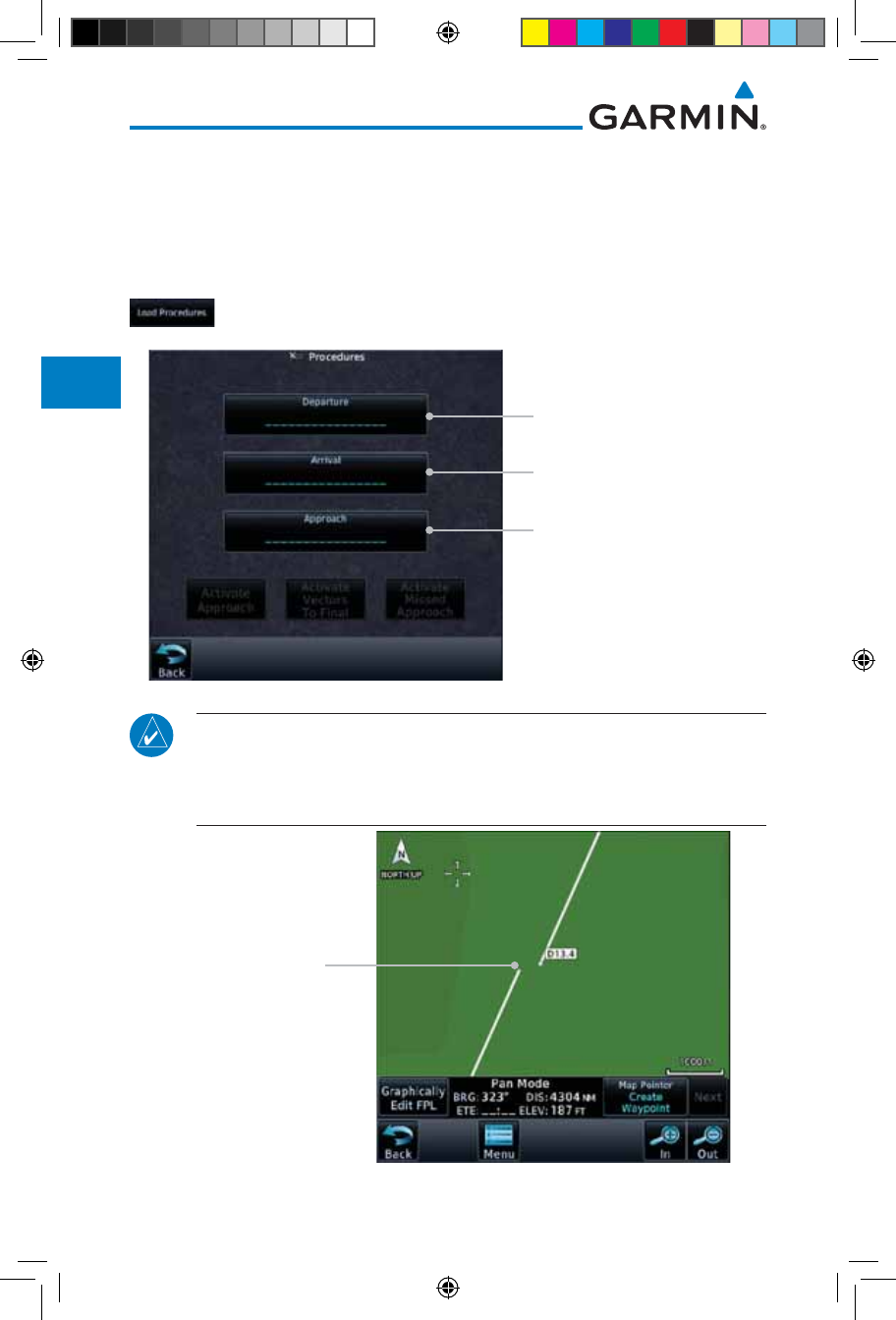
4-10
Garmin GTN 725/750 Pilot’s Guide
190-01007-03 Rev. J
Foreword
Getting
Started
Audio &
Xpdr Ctrl
Com/Nav
FPL
Direct-To
Proc
Charts
Wpt Info
Map
Traffic
Terrain
Weather
Nearest
Services/
Music
Utilities
System
Messages
Symbols
Appendix
Index
4.2.1.5 Load Procedures
The Load Procedure selection from the Waypoint Options will start the
Procedures function. See the Procedures section for complete information.
1. On the Active Flight Plan page, touch the desired waypoint in
the flight plan. The Waypoint Options list will be displayed.
2. Touch the Load Procedures key to go to the Procedure
function for adding procedures to the selected flight plan.
Touch to Select an Approach
Touch to Select an Arrival
Touch to Select a Departure
Figure 4-14 Load Procedures Wpt Option
NOTE: In software version 5.13 and earlier, for some procedures, due to
very small position differences in the database, consecutive flight plan legs
do not match up. The total effect on navigational guidance is negligible.
The LOC BC 13 at KSLE via UBG shown below is an example of this.
Procedure Flight Plan
Leg Discrepancy
Figure 4-15 Procedure Flight Plan Leg Position Difference
190-01007-03-Final.indb 10 7/9/2015 2:07:05 PM
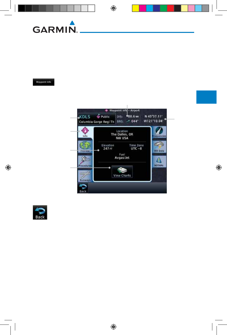
4-11190-01007-03 Rev. J
Garmin GTN 725/750 Pilot’s Guide
Foreword
Getting
Started
Audio &
Xpdr Ctrl
Com/Nav
FPL
Direct-To
Proc
Charts
Wpt Info
Map
Traffic
Terrain
Weather
Nearest
Services/
Music
Utilities
System
Messages
Symbols
Appendix
Index
4.2.1.6 Waypoint Info
The Waypoint Info option allows you to view information about the selected
waypoint. See the Waypoint Info section for complete information.
1. On the Active Flight Plan page, touch the desired waypoint in
the flight plan. The Waypoint Options list will be displayed.
2. One Waypoint Options menu, touch the Waypoint Info key
to view information about the selected waypoint.
Distance & Bearing To Airport
From Current Position
Waypoint Info
Page Tab
Airport
Identifier, City,
& Type
Airport
Information
Touch To
View Airport
Charts
Airport
Lat/Lon
Figure 4-16 Active Flight Plan Wpt Info
3. Touch the Back key to return to the Active Flight Plan page.
190-01007-03-Final.indb 11 7/9/2015 2:07:05 PM
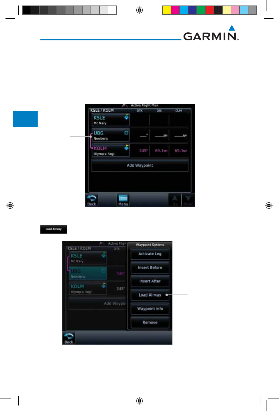
4-12
Garmin GTN 725/750 Pilot’s Guide
190-01007-03 Rev. J
Foreword
Getting
Started
Audio &
Xpdr Ctrl
Com/Nav
FPL
Direct-To
Proc
Charts
Wpt Info
Map
Traffic
Terrain
Weather
Nearest
Services/
Music
Utilities
System
Messages
Symbols
Appendix
Index
4.2.2 Airways
Airways may be added as legs in flight plans with any waypoint that is part
of an airway, such as a VOR.
1. On the Active Flight Plan page, touch the desired airway entry
waypoint in the flight plan. The Waypoint Options list will then
be displayed.
Touch VOR
Entry Wpt To
Insert Airway
Figure 4-17 Active Flight Plan with VOR Entry Wpt
2. Touch the Load Airway key to select an airway for the selected
entry waypoint.
Touch To
Insert Airway
Figure 4-18 Select Load Airway from the Waypoint Options
190-01007-03-Final.indb 12 7/9/2015 2:07:05 PM
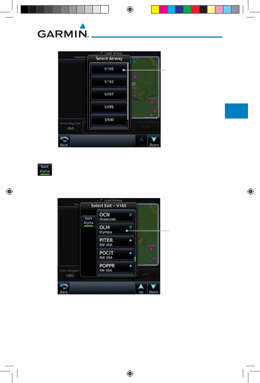
4-13190-01007-03 Rev. J
Garmin GTN 725/750 Pilot’s Guide
Foreword
Getting
Started
Audio &
Xpdr Ctrl
Com/Nav
FPL
Direct-To
Proc
Charts
Wpt Info
Map
Traffic
Terrain
Weather
Nearest
Services/
Music
Utilities
System
Messages
Symbols
Appendix
Index
3. Touch the desired airway to select it.
Touch To Insert
Selected Airway
Figure 4-19 Select an Airway from the List
4. Scroll through the list and touch the desired exit point from
the airway. The Airway list can be sorted by distance or
alphabetically. Touch the Sort Alpha key to toggle the sort
setting.
Touch To Select
Exit Waypoint
Figure 4-20 Select an Exit Waypoint for the Airway
190-01007-03-Final.indb 13 7/9/2015 2:07:05 PM
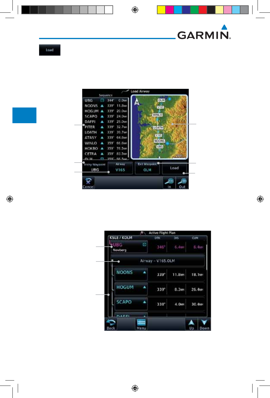
4-14
Garmin GTN 725/750 Pilot’s Guide
190-01007-03 Rev. J
Foreword
Getting
Started
Audio &
Xpdr Ctrl
Com/Nav
FPL
Direct-To
Proc
Charts
Wpt Info
Map
Traffic
Terrain
Weather
Nearest
Services/
Music
Utilities
System
Messages
Symbols
Appendix
Index
5. Confirm the airway information and then touch Load to insert
the selected airway into the flight plan. Use the In and Out
keys, and drag the map with your finger to view the airway
detail. If changes are desired, touch the Airway or Exit
Waypoint keys to select alternate choices.
Touch To Select
Exit Waypoint
Touch To Load
Airway Into FPL
Airway
Waypoint List
Entry Waypoint
Selected Airway
Map Preview
Of Airway
Waypoints
Figure 4-21 Airway Information
6. After loading the airway, it is inserted into the flight plan. The
airway waypoints are shown below the Airway key on the
display. Touch the airway to make any changes.
Entry Waypoint
Selected Airway.
Touch To Edit.
Selected Airway
Waypoints
Figure 4-22 Airway Waypoints in the Flight Plan
190-01007-03-Final.indb 14 7/9/2015 2:07:05 PM
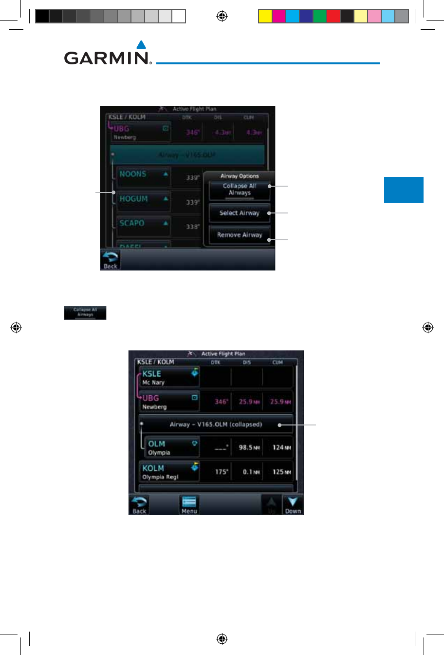
4-15190-01007-03 Rev. J
Garmin GTN 725/750 Pilot’s Guide
Foreword
Getting
Started
Audio &
Xpdr Ctrl
Com/Nav
FPL
Direct-To
Proc
Charts
Wpt Info
Map
Traffic
Terrain
Weather
Nearest
Services/
Music
Utilities
System
Messages
Symbols
Appendix
Index
7. Touch the Airway key to display the Airway Options. Make
the desired choice or touch Back.
Touch To Collapse
Airway Waypoints
Touch To Select New or
Change Current Airway
Touch To Remove
Airway From Flight Plan
Airway
Detail
Shown
Figure 4-23 Airway Options
8. Touch the Collapse All Airways key to collapse the list of
points along the airway. Touch the Collapse All Airways key
again to toggle the display of airway detail back on.
Touch To Expand
Airway Waypoints
Figure 4-24 Airways Collapsed In Flight Plan
190-01007-03-Final.indb 15 7/9/2015 2:07:06 PM
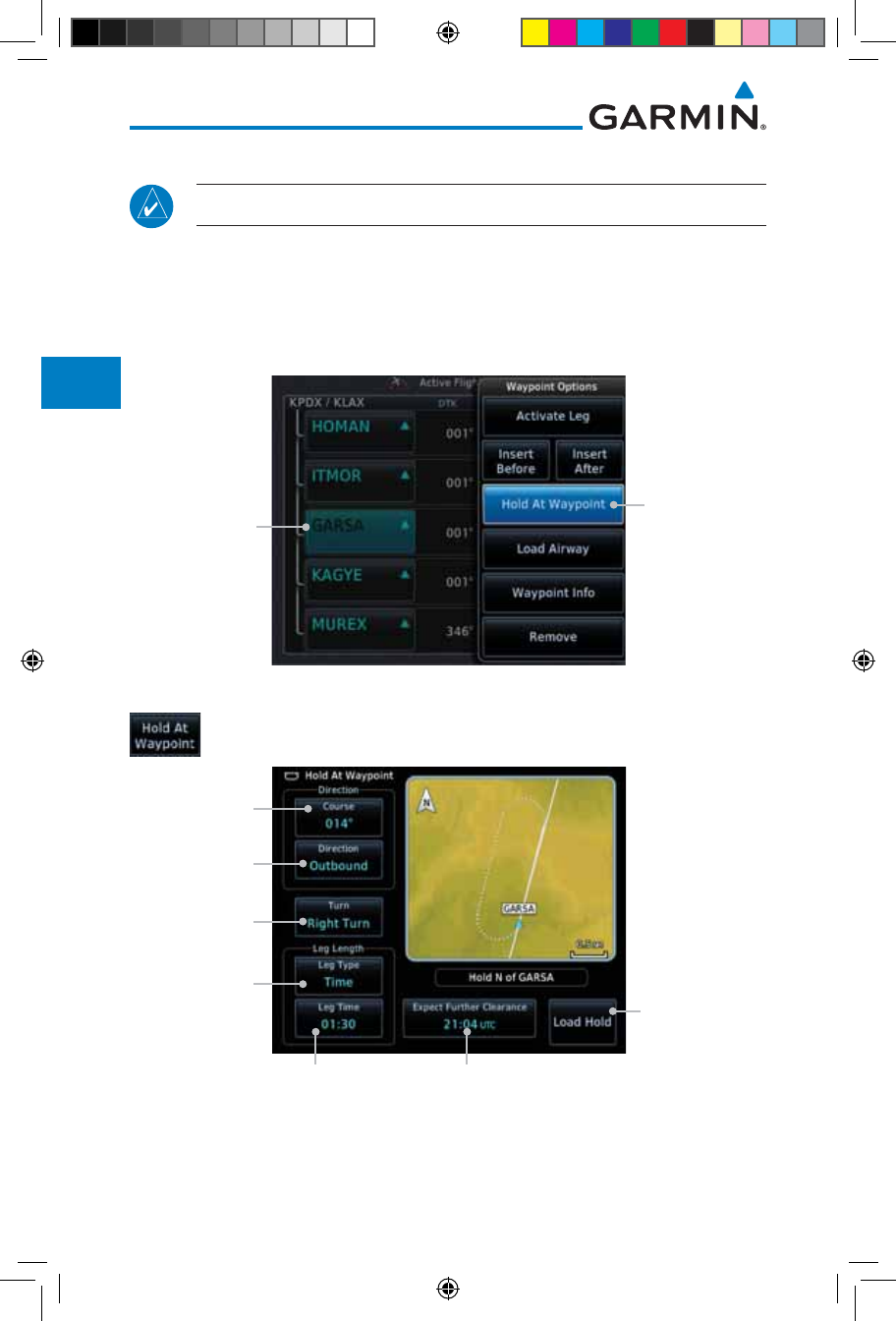
4-16
Garmin GTN 725/750 Pilot’s Guide
190-01007-03 Rev. J
Foreword
Getting
Started
Audio &
Xpdr Ctrl
Com/Nav
FPL
Direct-To
Proc
Charts
Wpt Info
Map
Traffic
Terrain
Weather
Nearest
Services/
Music
Utilities
System
Messages
Symbols
Appendix
Index
4.2.3 Load Hold at Waypoint
NOTE: This feature is available in software version 6.00 and later.
4.2.3.1 Hold at Waypoint
Holding patterns may be added to existing waypoints within the flight plan.
1. On the Active Flight Plan page, touch the desired waypoint in
the flight plan. The Waypoint Options list will then be displayed.
Hold At
Waypoint
Option Selected
Option Will Hold
At This Waypoint
Figure 4-25 Active Flight Plan with Hold At Waypoint Option
2. Touch the Hold At Waypoint key to open the Hold at
Waypoint dialog window.
Touch To Select
Hold Course
Touch To
Select Course
Direction
Touch To Select
Turn Direction
Touch To Select
Leg Length
Type
Touch To Enter
Leg Length
Touch To Select
EFC Time
Touch To Use
Selections To
Create A Hold
At The Selected
Waypoint
Figure 4-26 Creating a User-Defined Hold
190-01007-03-Final.indb 16 7/9/2015 2:07:06 PM
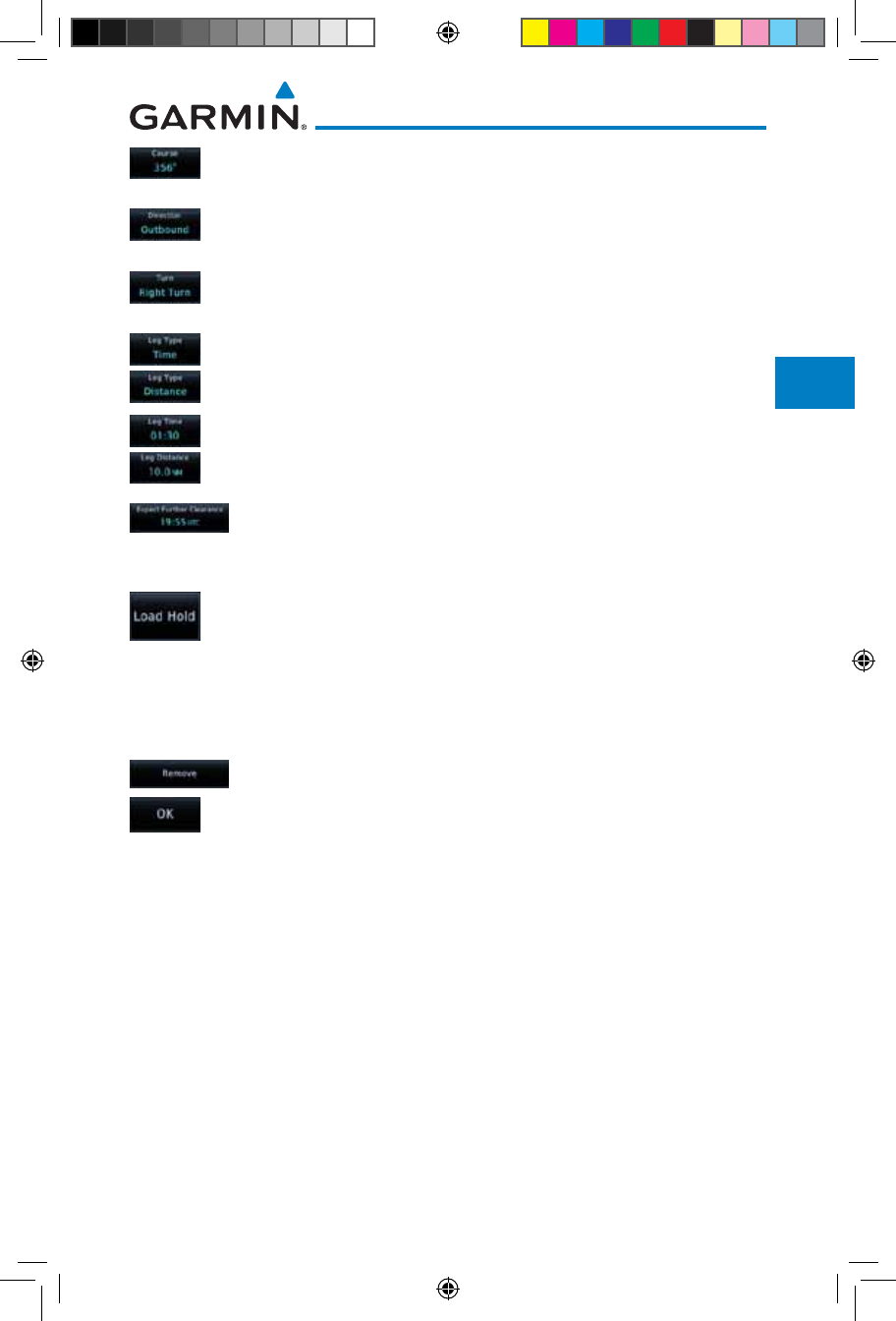
4-17190-01007-03 Rev. J
Garmin GTN 725/750 Pilot’s Guide
Foreword
Getting
Started
Audio &
Xpdr Ctrl
Com/Nav
FPL
Direct-To
Proc
Charts
Wpt Info
Map
Traffic
Terrain
Weather
Nearest
Services/
Music
Utilities
System
Messages
Symbols
Appendix
Index
3. Touch the Course key to open the keypad. Use the keypad
and Enter to select the inbound or outbound course.
4. Touch the Direction key to select between Inbound or
Outbound for the course direction.
5. Touch the Turn key to select between Left or Right for the turn
direction.
6. Touch the Leg Type key to select between Time or Distance
for the leg type.
7. Touch the Leg Time or Leg Distance key to display the
keypad. Use the keypad and the Enter key to select the length
of the leg.
8. Touch the Expect Further Clearance key to display the
keypad. Use the keypad and the Enter key to select the time
for a reminder.
9. Touch the Load Hold key to add the hold into the flight plan.
4.2.3.2 Removing a Hold
1. On the Active Flight Plan page, touch the hold to be removed.
The Hold Options window is displayed.
2. Touch the Remove key.
3. Touch the OK key in response to “Remove Holding Pattern?”
The holding pattern is removed. To cancel the request, touch
the Cancel key.
190-01007-03-Final.indb 17 7/9/2015 2:07:06 PM
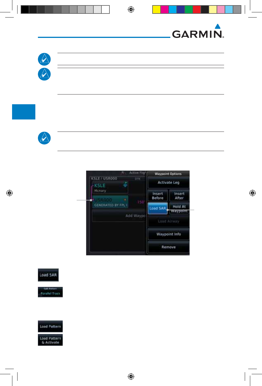
4-18
Garmin GTN 725/750 Pilot’s Guide
190-01007-03 Rev. J
Foreword
Getting
Started
Audio &
Xpdr Ctrl
Com/Nav
FPL
Direct-To
Proc
Charts
Wpt Info
Map
Traffic
Terrain
Weather
Nearest
Services/
Music
Utilities
System
Messages
Symbols
Appendix
Index
4.2.4 Load Search and Rescue Patterns (Optional)
NOTE: This feature is available in software version 6.00 and later.
NOTE: Turn smoothing may result in SAR coverage being different than
intended. The flight crew should always verify that the SAR pattern created
conforms to the specific mission requirements.
Search and Rescue Patterns may be added to existing waypoints within
the active flight plan. Only one SAR pattern can exist in the active flight plan.
Loading another SAR pattern into the active flight plan when one already exists
will remove the first SAR pattern.
NOTE: Flight plans cannot be stored in the catalog if they contain a SAR
pattern.
1. On the Active Flight Plan page, touch the desired waypoint in
the flight plan. The Waypoint Options list will then be displayed.
Load SAR
Option Was
Selected
Option will
initiate SAR
pattern from this
waypoint
Figure 4-27 Active Flight Plan with Load SAR Option
2. Touch the Load SAR key to open the Search and Rescue
Patterns page.
3. Touch the SAR Pattern key to select between Parallel Track,
Sector Search, Expanding Square, or Orbit for the SAR pattern
type. The available patterns can be configured by the installer
and all of the listed pattern types may not be available.
4. Confirm the SAR pattern information and then touch the Load
Pattern key to load selected pattern to the active flight plan
or touch the Load Pattern & Activate key to load selected
190-01007-03-Final.indb 18 7/9/2015 2:07:06 PM

4-19190-01007-03 Rev. J
Garmin GTN 725/750 Pilot’s Guide
Foreword
Getting
Started
Audio &
Xpdr Ctrl
Com/Nav
FPL
Direct-To
Proc
Charts
Wpt Info
Map
Traffic
Terrain
Weather
Nearest
Services/
Music
Utilities
System
Messages
Symbols
Appendix
Index
pattern to the active flight plan and go direct-to the initial
waypoint.
5. The SAR pattern waypoints are shown below the SAR key on
the display. Touch the SAR pattern to make any changes.
Initial Waypoint
SAR Key.
Selected Pattern.
Touch To Edit.
Selected
SAR Pattern
Waypoints
Figure 4-28 SAR Pattern Waypoints in the Flight Plan
6. Touch the SAR key to display the Search & Rescue Options.
Make the desired choice or touch the Back key.
Touch To Collapse
SAR Pattern
SAR Pattern
Detail Shown
Touch To Insert Wpt
Before SAR Wpts
Touch To Edit SAR
Pattern Parameters
Touch To Remove
SAR Pattern
SAR Key
Figure 4-29 Search & Rescue Options
190-01007-03-Final.indb 19 7/9/2015 2:07:07 PM
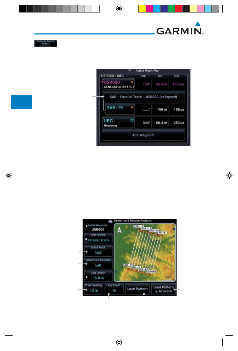
4-20
Garmin GTN 725/750 Pilot’s Guide
190-01007-03 Rev. J
Foreword
Getting
Started
Audio &
Xpdr Ctrl
Com/Nav
FPL
Direct-To
Proc
Charts
Wpt Info
Map
Traffic
Terrain
Weather
Nearest
Services/
Music
Utilities
System
Messages
Symbols
Appendix
Index
7. Touch the Collapse Search Pattern key to collapse the list of
the points along the SAR pattern. Touch the Collapse Search
Pattern key again to toggle the display of SAR pattern detail
back on.
SAR Pattern Collapsed
Figure 4-30 SAR Pattern Collapsed in Flight Plan
4.2.4.1 Creating a Parallel Track Pattern
The Parallel Track SAR pattern starts at the initial waypoint and follows the
initial track for the length of the first parallel track leg. A 90° turn in the initial
turn direction leads to the spacing leg with a length equal to the track spacing.
Another 90° turn leads to the second parallel track leg. The turns at the end
of the second parallel track leg are in the opposite direction as the previous
parallel track leg. The parallel track pattern terminates once the desired number
of parallel track legs have been flown.
Selected Initial
Waypoint
Touch To Select
SAR Pattern
Touch To Select
Initial Track
Touch To Select Initial
Turn Direction
Touch To Select Leg
Length
Touch To Select Track
Spacing Distance
Touch To Select
Number of Legs
Touch
To Load
Selected
Pattern To
The Active
FPL And
Go Direct-
To The First
Wpt In The
Pattern
Touch To Load Selected
Pattern To Active FPL
Figure 4-31 Search and Rescue Parallel Track Pattern Page
190-01007-03-Final.indb 20 7/9/2015 2:07:07 PM
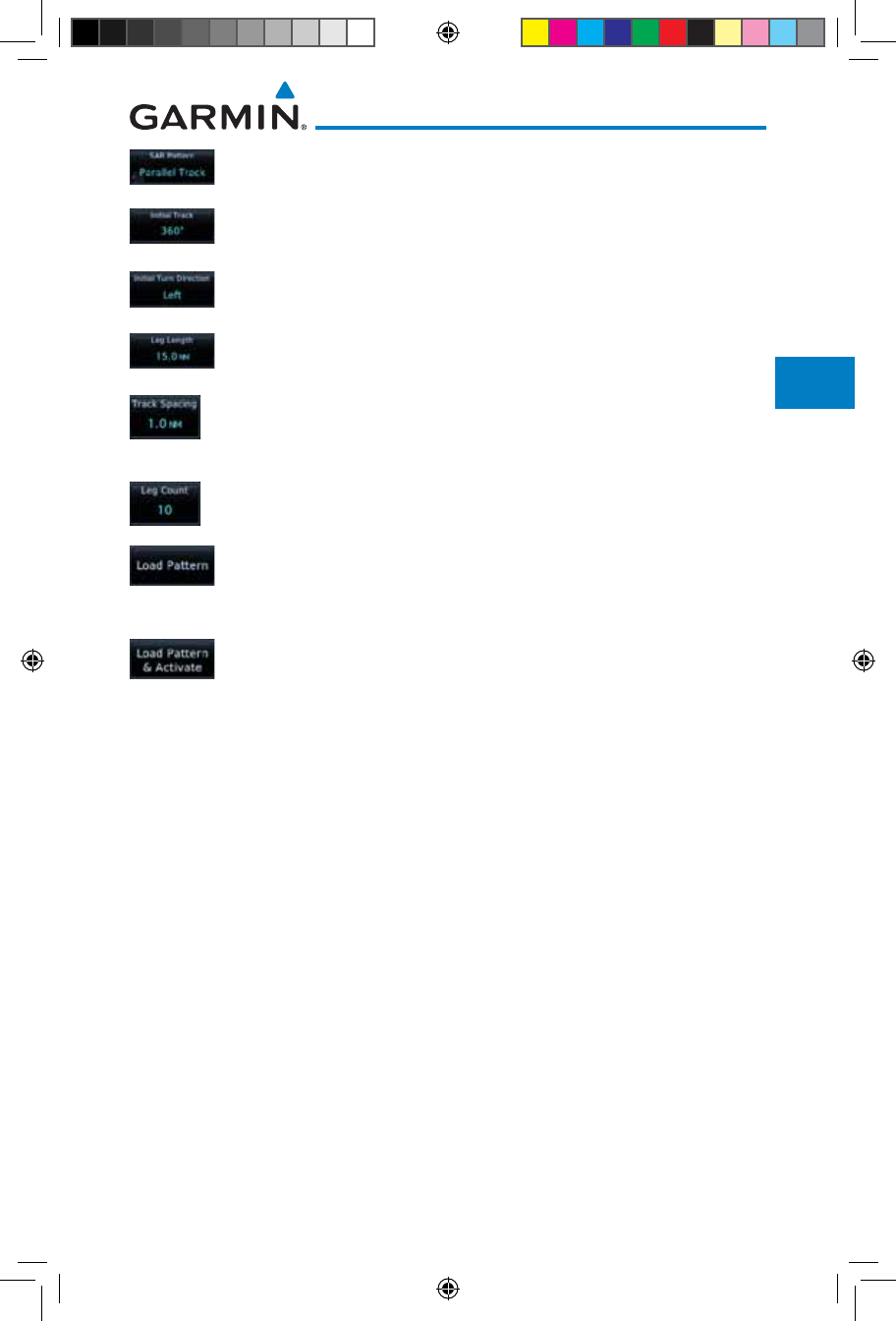
4-21190-01007-03 Rev. J
Garmin GTN 725/750 Pilot’s Guide
Foreword
Getting
Started
Audio &
Xpdr Ctrl
Com/Nav
FPL
Direct-To
Proc
Charts
Wpt Info
Map
Traffic
Terrain
Weather
Nearest
Services/
Music
Utilities
System
Messages
Symbols
Appendix
Index
1. Touch the SAR Pattern key and select Parallel Track as the
pattern type.
2. Touch the Initial Track key to open the keypad. Use the keypad
and Enter to select the initial course.
3. Touch the Initial Turn Direction key to select between Left
or Right as the initial turn direction.
4. Touch the Leg Length key to open the keypad. Use the keypad
and Enter to select the length of the parallel track legs.
5. Touch the Track Spacing key to open the keypad. Use the
keypad and Enter to select the desired spacing between the
parallel track legs.
6. Touch the Leg Count key to open the keypad. Use the keypad
and Enter to select the desired number of parallel track legs.
7. Touch the Load Pattern key to load selected pattern to the
active flight plan.
Or
8. Touch the Load Pattern & Activate key to load selected
pattern to the active flight plan and go direct-to the initial
waypoint.
190-01007-03-Final.indb 21 7/9/2015 2:07:07 PM
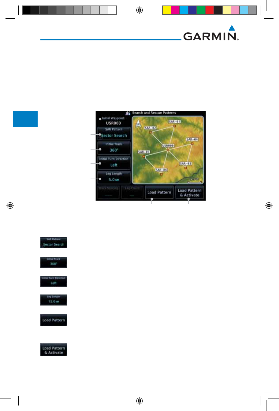
4-22
Garmin GTN 725/750 Pilot’s Guide
190-01007-03 Rev. J
Foreword
Getting
Started
Audio &
Xpdr Ctrl
Com/Nav
FPL
Direct-To
Proc
Charts
Wpt Info
Map
Traffic
Terrain
Weather
Nearest
Services/
Music
Utilities
System
Messages
Symbols
Appendix
Index
4.2.4.2 Creating a Sector Search Pattern
The Sector Search SAR pattern starts at the initial waypoint and follows the
initial track for the desired leg length. A 60° turn in the initial turn direction is
followed by another leg with the desired leg length, another 60° turn, and then
a leg back to the initiating waypoint. The next sector starts with a leg continuing
on the same course outbound from the initiating waypoint and is followed by
the same sequence of legs and turns. The third sector follows the same pattern.
Selected Initial
Waypoint
Sector Search
Pattern Selected
Touch To Select
Initial Track
Touch To Select Initial
Turn Direction
Touch To Select Leg
Length
Touch To Load Selected
Pattern To Active FPL
Touch To Load Selected Pattern
To Active FPL & Go Direct-To
Initial Wpt
Figure 4-32 Search and Rescue Sector Search Pattern Page
1. Touch the SAR Pattern key and select Sector Search as the
pattern type.
2. Touch the Initial Track key to open the keypad. Use the keypad
and Enter to select the initial course.
3. Touch the Initial Turn Direction key to select between Left
or Right as the initial turn direction.
4. Touch the Leg Length key to open the keypad. Use the keypad
and Enter to select the length of the parallel track legs.
5. Touch the Load Pattern key to load selected pattern to the
active flight plan.
Or
6. Touch the Load Pattern & Activate key to load selected
pattern to the active flight plan and go direct-to the initial
waypoint.
190-01007-03-Final.indb 22 7/9/2015 2:07:07 PM
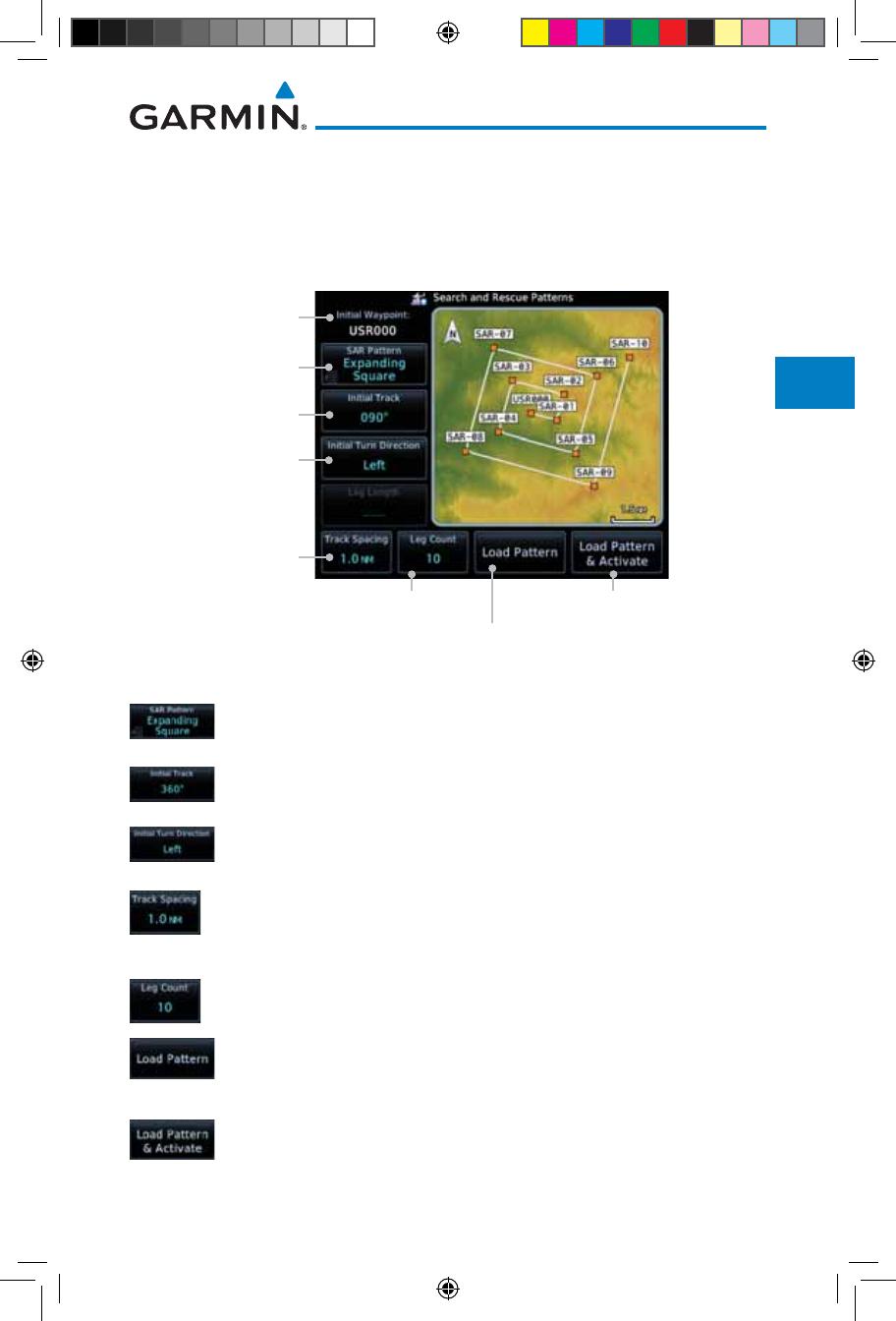
4-23190-01007-03 Rev. J
Garmin GTN 725/750 Pilot’s Guide
Foreword
Getting
Started
Audio &
Xpdr Ctrl
Com/Nav
FPL
Direct-To
Proc
Charts
Wpt Info
Map
Traffic
Terrain
Weather
Nearest
Services/
Music
Utilities
System
Messages
Symbols
Appendix
Index
4.2.4.3 Creating an Expanding Square Pattern
The Expanding Square SAR pattern starts at the initial waypoint and
follows the initial track for a distance equal to the track spacing. All turns in
the expanding square pattern are in the initial turn direction. All legs in the
expanding square pattern are separated by the track spacing distance.
Selected Initial
Waypoint
Expanding Square
Pattern Selected
Touch To Select
Initial Track
Touch To Select Initial
Turn Direction
Touch To Select Track
Spacing Distance
Touch To Select Number of Legs Touch To Load Selected Pattern
To Active FPL & Go Direct-To
Initial Wpt
Touch To Load Selected
Pattern To Active FPL
Figure 4-33 Search and Rescue Expanding Square Pattern Page
1. Touch the SAR Pattern key and select Expanding Square as
the pattern type.
2. Touch the Initial Track key to open the keypad. Use the keypad
and Enter to select the initial course.
3. Touch the Initial Turn Direction key to select between Left
or Right as the initial turn direction.
4. Touch the Track Spacing key to open the keypad. Use the
keypad and Enter to select the desired spacing between the
parallel track legs.
5. Touch the Leg Count key to open the keypad. Use the keypad
and Enter to select the desired number of legs.
6. Touch the Load Pattern key to load selected pattern to the
active flight plan.
OR
7. Touch the Load Pattern & Activate key to load selected
pattern to the active flight plan and go direct-to the initial
waypoint.
190-01007-03-Final.indb 23 7/9/2015 2:07:07 PM
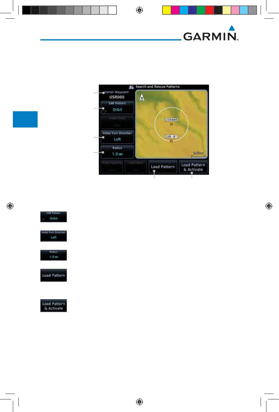
4-24
Garmin GTN 725/750 Pilot’s Guide
190-01007-03 Rev. J
Foreword
Getting
Started
Audio &
Xpdr Ctrl
Com/Nav
FPL
Direct-To
Proc
Charts
Wpt Info
Map
Traffic
Terrain
Weather
Nearest
Services/
Music
Utilities
System
Messages
Symbols
Appendix
Index
4.2.4.4 Creating an Orbit Pattern
The Orbit SAR pattern is a fixed radius turn around the specified center
waypoint. Automatic waypoint sequencing will be suspended while flying the
orbit pattern.
Selected Initial
Waypoint
Orbit Search
Pattern Selected
Touch To Select Initial
Turn Direction
Touch To Load Selected Pattern
To Active FPL & Go Direct-To
Initial Wpt
Touch To Load Selected
Pattern To Active FPL
Touch To Select Radius
Figure 4-34 Search and Rescue Orbit Pattern Page
1. Touch the SAR Pattern key and select Orbit as the pattern
type.
2. Touch the Initial Turn Direction key to select between Left
or Right as the turn direction.
3. Touch the Radius key to open the keypad. Use the keypad
and Enter to select the radius of the orbit pattern.
4. Touch the Load Pattern key to load selected pattern to the
active flight plan.
OR
5. Touch the Load Pattern & Activate key to load selected
pattern to the active flight plan and go direct-to the first
waypoint in the pattern.
190-01007-03-Final.indb 24 7/9/2015 2:07:08 PM
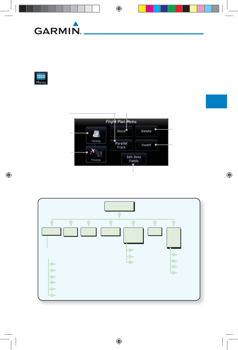
4-25190-01007-03 Rev. J
Garmin GTN 725/750 Pilot’s Guide
Foreword
Getting
Started
Audio &
Xpdr Ctrl
Com/Nav
FPL
Direct-To
Proc
Charts
Wpt Info
Map
Traffic
Terrain
Weather
Nearest
Services/
Music
Utilities
System
Messages
Symbols
Appendix
Index
4.3 Flight Plan Menu
The Flight Plan Menu provides access to functions to manage your flight
plans. The functions included are: View Catalog, Store Flight Plan, Delete Flight
Plan, Preview Flight Plan, Parallel Track, Invert Flight Plan, and Edit Data Fields.
Touch the Menu key to access the Flight Plan Menu options:
View Catalog, Store Flight Plan, Delete Flight Plan, Preview
Flight Plan, Parallel Track, Invert Flight Plan, and Edit Data
Fields.
Touch To Invert
The Active
Flight Plan
Touch To Store
The Active
Flight Plan
Touch To View
List Of Stored
Flight Plans
Touch To Add
Parallel Track
Course Offsets
Touch To Edit The
Active Flight Plan
Information Fields
Touch To View A
Map And A List Of
Waypoints For The
Active Flight Plan
Touch To Delete
The Active
Flight Plan
Figure 4-35 Flight Plan Menu
Menu
InvertStore
Activate
Invert & Activate
Preview
Edit
Copy
Delete
Route
Options
Catalog Delete Preview Parallel
Track
Direction
Offset
Activate
Edit
Data
Fields
Column 1
Column 2
Column 3
Restore
Defaults
Figure 4-36 Flight Plan Menu Functional Diagram
190-01007-03-Final.indb 25 7/9/2015 2:07:08 PM
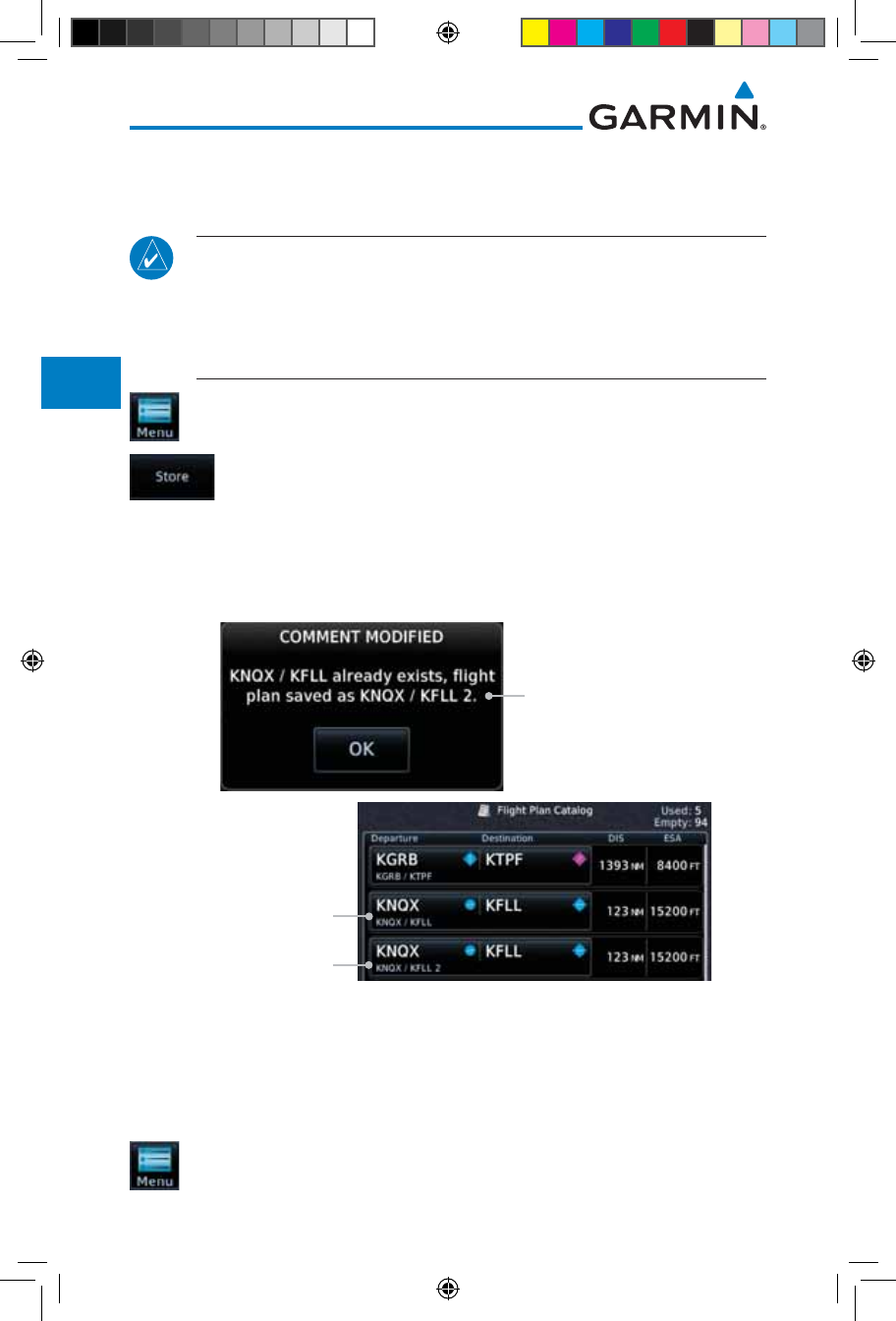
4-26
Garmin GTN 725/750 Pilot’s Guide
190-01007-03 Rev. J
Foreword
Getting
Started
Audio &
Xpdr Ctrl
Com/Nav
FPL
Direct-To
Proc
Charts
Wpt Info
Map
Traffic
Terrain
Weather
Nearest
Services/
Music
Utilities
System
Messages
Symbols
Appendix
Index
4.3.1 Store Flight Plan
A flight plan must be saved to the Catalog to be used in future flights. The
Store Flight Plan function will save the Active Flight Plan to the Catalog.
NOTE: If a flight plan that includes a procedure that has been modified
by the pilot is saved into the flight plan catalog, the GTN cannot check the
accuracy of that procedure when that flight plan is used on a later flight. It
is recommended that flight plans with modified procedures not be saved
in the flight plan catalog.
1. While viewing the Active Flight Plan page, touch the Menu
key. The Flight Plan Menu will be displayed.
2. Touch the Store key to store the current Active Flight Plan into
the Catalog. The flight plan will be named by the beginning
and ending waypoints.
3. When a duplicate flight plan is created, a warning dialog will
appear and the flight plan will be saved with a numeral at the
end of the destination waypoint.
Duplicate Flight Plan
Original Flight Plan
Duplicate Flight Plan
Figure 4-37 Duplicate Flight Plan Naming
4.3.2 Invert Flight Plan
The Invert Flight Plan option allows you to reverse the Active flight plan and
use it for navigation guidance back to your original departure point. The original
flight plan stored in the catalog is not affected.
1. While viewing the Active Flight Plan page, touch the Menu
key. The Flight Plan Menu will be displayed.
190-01007-03-Final.indb 26 7/9/2015 2:07:08 PM
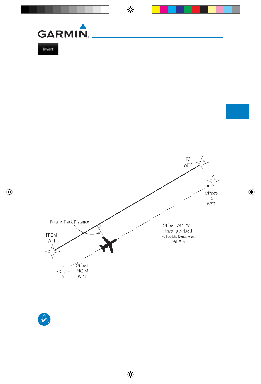
4-27190-01007-03 Rev. J
Garmin GTN 725/750 Pilot’s Guide
Foreword
Getting
Started
Audio &
Xpdr Ctrl
Com/Nav
FPL
Direct-To
Proc
Charts
Wpt Info
Map
Traffic
Terrain
Weather
Nearest
Services/
Music
Utilities
System
Messages
Symbols
Appendix
Index
2. Touch the Invert key to invert the current Active Flight Plan.
4.3.3 Parallel Track
Parallel Track allows you to create a parallel course offset of 1 to 99 NM to
the left or right of your current flight plan. After setting a parallel track to your
current flight plan, a magenta parallel track line will be drawn offset from the
original by the selected distance. The original course line will be drawn in grey.
The aircraft will navigate to the parallel track course line and external CDI/HSI
guidance will be driven from the parallel track.
When you reach the end of the flight plan, a message will state, “Parallel
offset terminating in X seconds.” The message will be given when the aircraft
reaches the offset distance from the end of the parallel track. This will give the
pilot sufficient time to intercept the original course.
Figure 4-38 Parallel Track Description
NOTE: Parallel track will be cancelled when graphically editing a flight
plan.
190-01007-03-Final.indb 27 7/9/2015 2:07:08 PM
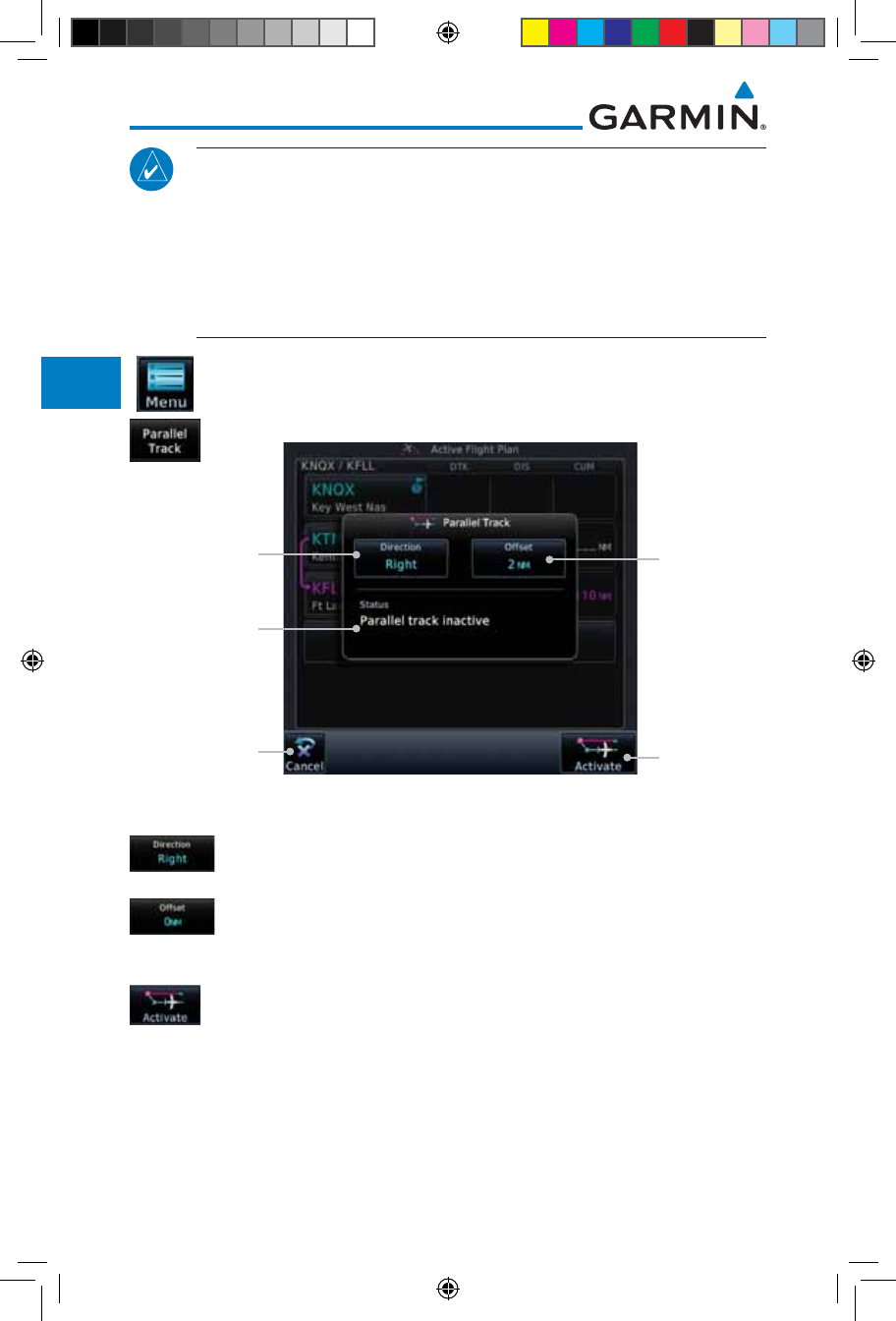
4-28
Garmin GTN 725/750 Pilot’s Guide
190-01007-03 Rev. J
Foreword
Getting
Started
Audio &
Xpdr Ctrl
Com/Nav
FPL
Direct-To
Proc
Charts
Wpt Info
Map
Traffic
Terrain
Weather
Nearest
Services/
Music
Utilities
System
Messages
Symbols
Appendix
Index
NOTE: Certain leg types (such as approach) or leg geometries (changes in
desire track greater than 120 degrees), combined with large offset values
do not support parallel track. Default direction and offset values may result
in the status indicating that parallel track is not supported. The user must
enter the desired parallel track offset and distance to determine whether
that flight plan, combined with the offset and distance, support parallel
track.
1. While viewing the Flight Plan page, touch the Menu key, and
then the Parallel Track key.
Touch To
Set PTK
Direction
PTK Status
Touch To
Set PTK
Distance
Touch To
Activate PTK
Settings
Touch To
Cancel Settings
Figure 4-39 Parallel Track Selection
2. Touch the Direction key to toggle the Parallel Track to be Left
or Right of the current Flight Plan.
3. Touch the Offset key to select the Parallel Offset from the
current Flight Plan. Select the desired distance on the numeric
keypad. Touch Enter when finished.
4. Touch the Activate key. A magenta "-P" indication will appear
to the right of the waypoint name on the Active Flight Plan
page.
190-01007-03-Final.indb 28 7/9/2015 2:07:09 PM
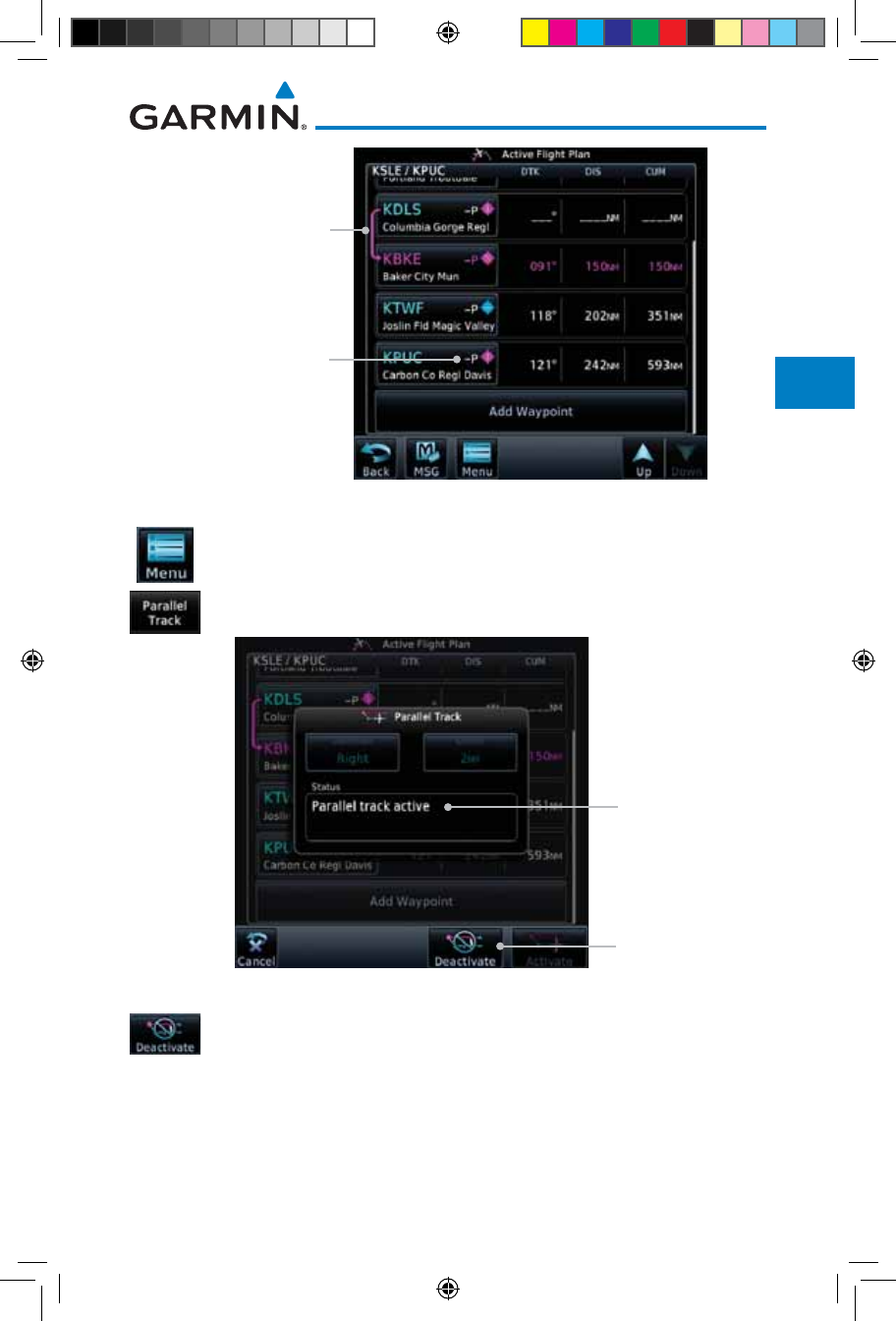
4-29190-01007-03 Rev. J
Garmin GTN 725/750 Pilot’s Guide
Foreword
Getting
Started
Audio &
Xpdr Ctrl
Com/Nav
FPL
Direct-To
Proc
Charts
Wpt Info
Map
Traffic
Terrain
Weather
Nearest
Services/
Music
Utilities
System
Messages
Symbols
Appendix
Index
PTK Active Symbol
Active FPL Leg
Figure 4-40 Parallel Track Shown in the Active Flight Plan Page
5. To deactivate Parallel Track, while viewing the Active Flight
Plan touch the Menu key. With the Flight Plan Menu displayed,
touch the Parallel Track key.
PTK Status
Touch To Deactivate
PTK Settings
Figure 4-41 Deactivating Parallel Track
6. Touch the Deactivate key to cancel Parallel Tracking.
190-01007-03-Final.indb 29 7/9/2015 2:07:09 PM
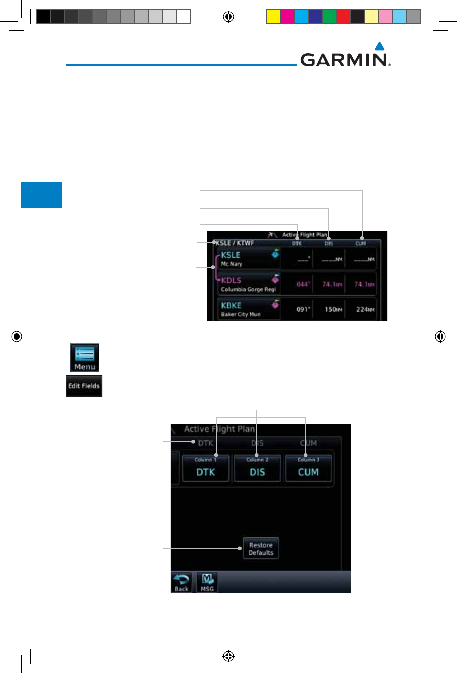
4-30
Garmin GTN 725/750 Pilot’s Guide
190-01007-03 Rev. J
Foreword
Getting
Started
Audio &
Xpdr Ctrl
Com/Nav
FPL
Direct-To
Proc
Charts
Wpt Info
Map
Traffic
Terrain
Weather
Nearest
Services/
Music
Utilities
System
Messages
Symbols
Appendix
Index
4.3.4 Edit Data Fields
The Active Flight Plan Page shows each waypoint for the flight plan, along
with the Desired Track (DTK), Distance (DIS) for each leg and Cumulative
Distance (CUM). The data fields are user-selectable and may be changed to
display Cumulative Distance (CUM), Distance (DIS), Desired Track (DTK), En
Route Safe Altitude (ESA), Estimated Time of Arrival (ETA), or Estimated Time
En route (ETE).
Origin and Destination Waypoints
Current Flight Plan Leg
DTK Between Legs
DIST Between Legs
Cumulative Dist Between
Current Position and Next Wpt
Figure 4-42 Flight Plan Data Fields
1. While viewing the Flight Plan page, touch the Menu key, and
then the Edit Data Fields key.
Touch To
Restore Original
Default Types
Current Field
Types
Touch To Select
Field Types
Figure 4-43 Flight Plan Edit Data Fields Page
190-01007-03-Final.indb 30 7/9/2015 2:07:09 PM
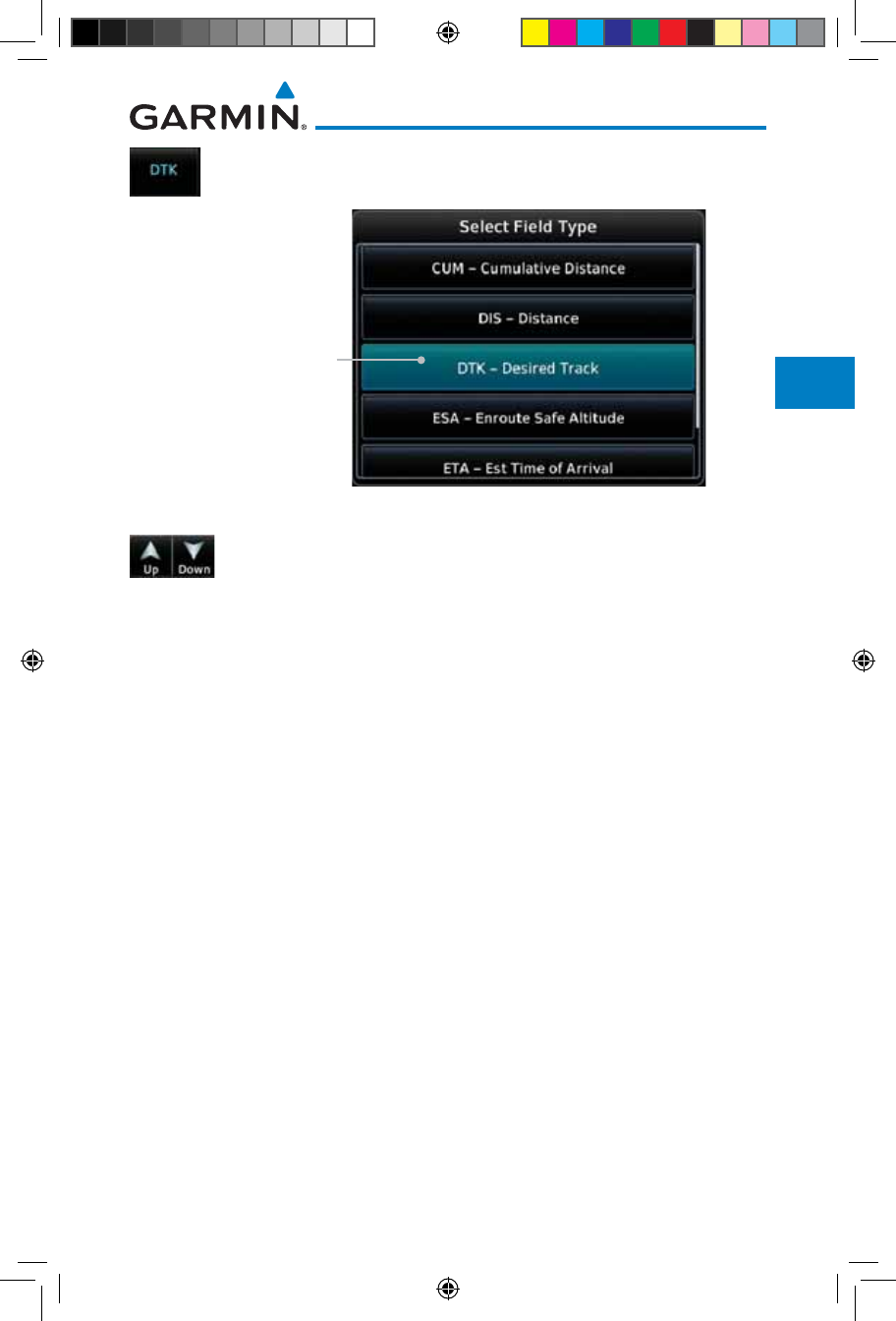
4-31190-01007-03 Rev. J
Garmin GTN 725/750 Pilot’s Guide
Foreword
Getting
Started
Audio &
Xpdr Ctrl
Com/Nav
FPL
Direct-To
Proc
Charts
Wpt Info
Map
Traffic
Terrain
Weather
Nearest
Services/
Music
Utilities
System
Messages
Symbols
Appendix
Index
2. Touch one of the field keys to select from the list.
Selected Field Type
Figure 4-44 Flight Plan Data Fields List
3. Touch the Up or Down keys as needed, or touch and drag
the list, to scroll through the list. Touch the desired Field Type
to set it for the selected field.
4. Continue as desired for the other fields.
190-01007-03-Final.indb 31 7/9/2015 2:07:09 PM
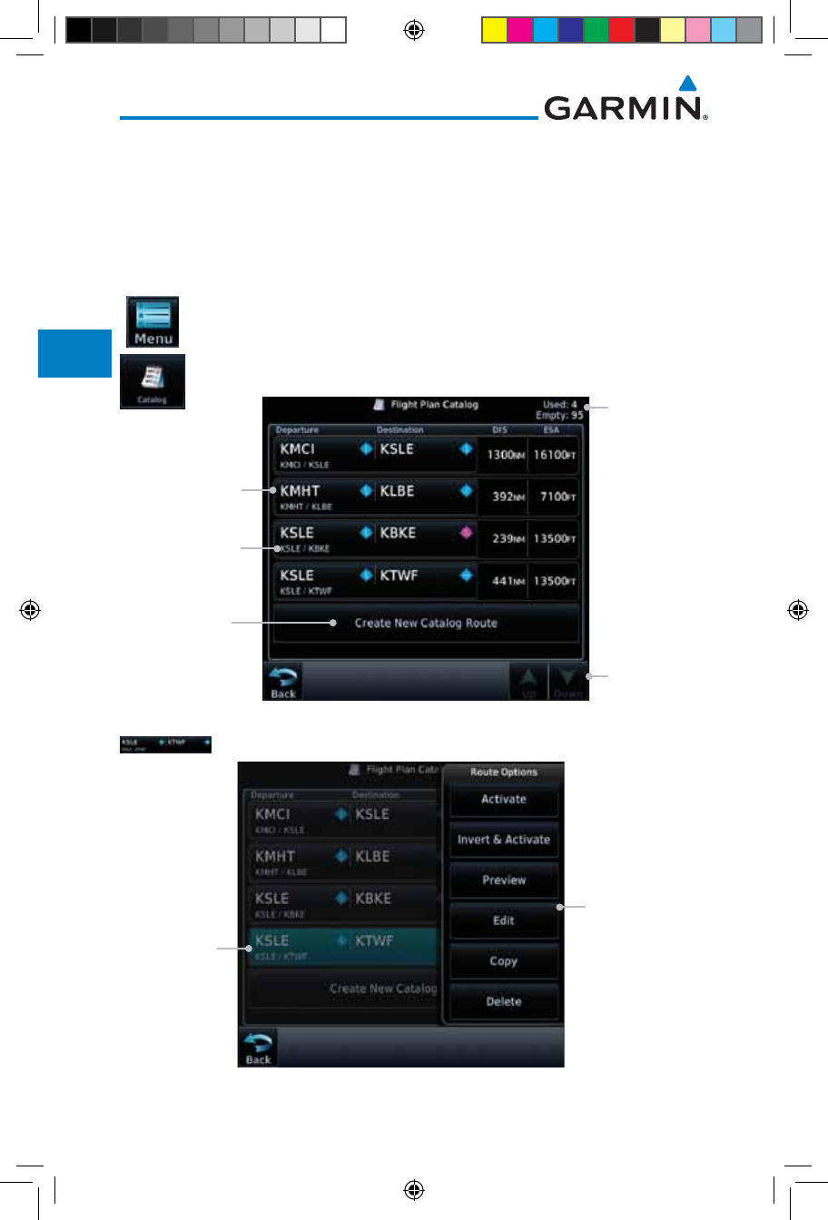
4-32
Garmin GTN 725/750 Pilot’s Guide
190-01007-03 Rev. J
Foreword
Getting
Started
Audio &
Xpdr Ctrl
Com/Nav
FPL
Direct-To
Proc
Charts
Wpt Info
Map
Traffic
Terrain
Weather
Nearest
Services/
Music
Utilities
System
Messages
Symbols
Appendix
Index
4.3.5 Flight Plan Catalog Route Options
The Flight Plan Catalog allows you to create, edit, activate, delete and copy
flight plans. The catalog can hold up to 99 flight plans of up to 100 waypoints
each. Flight plans are named by the Departure and Destination waypoint. Any
time you activate a flight plan, a copy of the flight plan is automatically transferred
to Active Flight Plan page and overwrites any previously active flight plan.
1. While viewing the Flight Plan page, touch the Menu key, and
then the Catalog key. The list of currently stored flight plans
will be displayed.
Flight Plan
Catalog Total
Flight Plan Name
Touch Up/
Down Keys To
Scroll List
Touch To Create
New Catalog
Route
(Flight Plan)
Flight Plan
Comment
Figure 4-45 Flight Plan Catalog
2. Touch a flight plan to display the Route Options.
Flight Plan
Route Options
Selected
Flight Plan
Figure 4-46 Flight Plan Catalog Route Options
190-01007-03-Final.indb 32 7/9/2015 2:07:09 PM
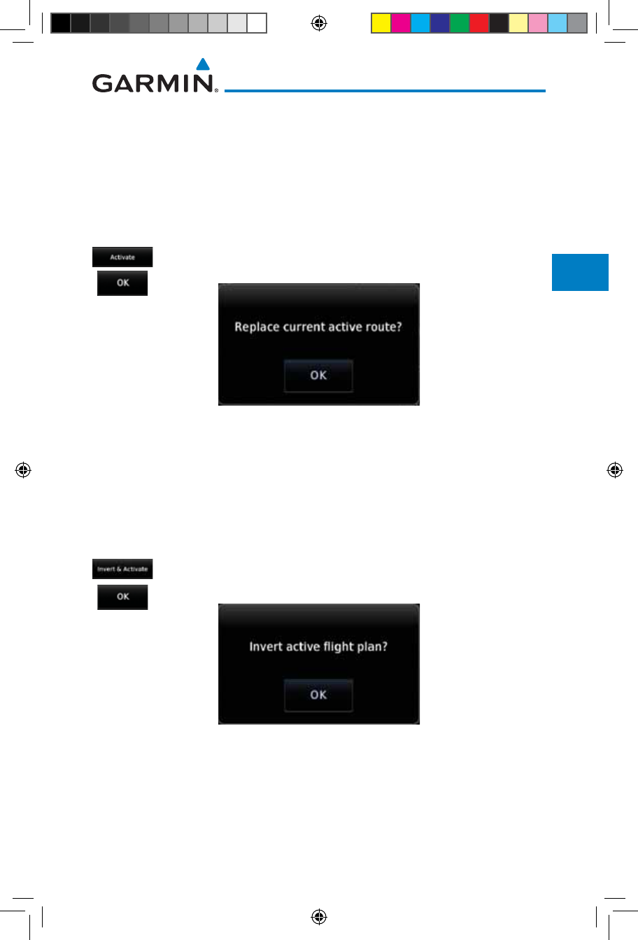
4-33190-01007-03 Rev. J
Garmin GTN 725/750 Pilot’s Guide
Foreword
Getting
Started
Audio &
Xpdr Ctrl
Com/Nav
FPL
Direct-To
Proc
Charts
Wpt Info
Map
Traffic
Terrain
Weather
Nearest
Services/
Music
Utilities
System
Messages
Symbols
Appendix
Index
3. Touch the Route Option key for the desired option to act on
the selected flight plan.
4.3.5.1 Catalog Route Option - Activate
1. While viewing the Flight Plan Catalog page, touch the desired
flight plan to select it. The Route Options menu will be
displayed.
2. Touch the Activate key and then touch OK. The selected flight
plan will be activated.
Figure 4-47 Touch OK to Replace the Existing Active Flight Plan
3. The Active Flight Plan page will now be displayed.
4.3.5.2 Catalog Route Option - Invert & Activate
1. While viewing the Flight Plan Catalog page, touch the desired
flight plan to select it. The Route Options menu will be
displayed.
2. Touch the Invert & Activate key and then touch OK. The
selected flight plan will be inverted and activated.
Figure 4-48 Touch OK to Invert and Activate the Selected Flight Plan
190-01007-03-Final.indb 33 7/9/2015 2:07:10 PM
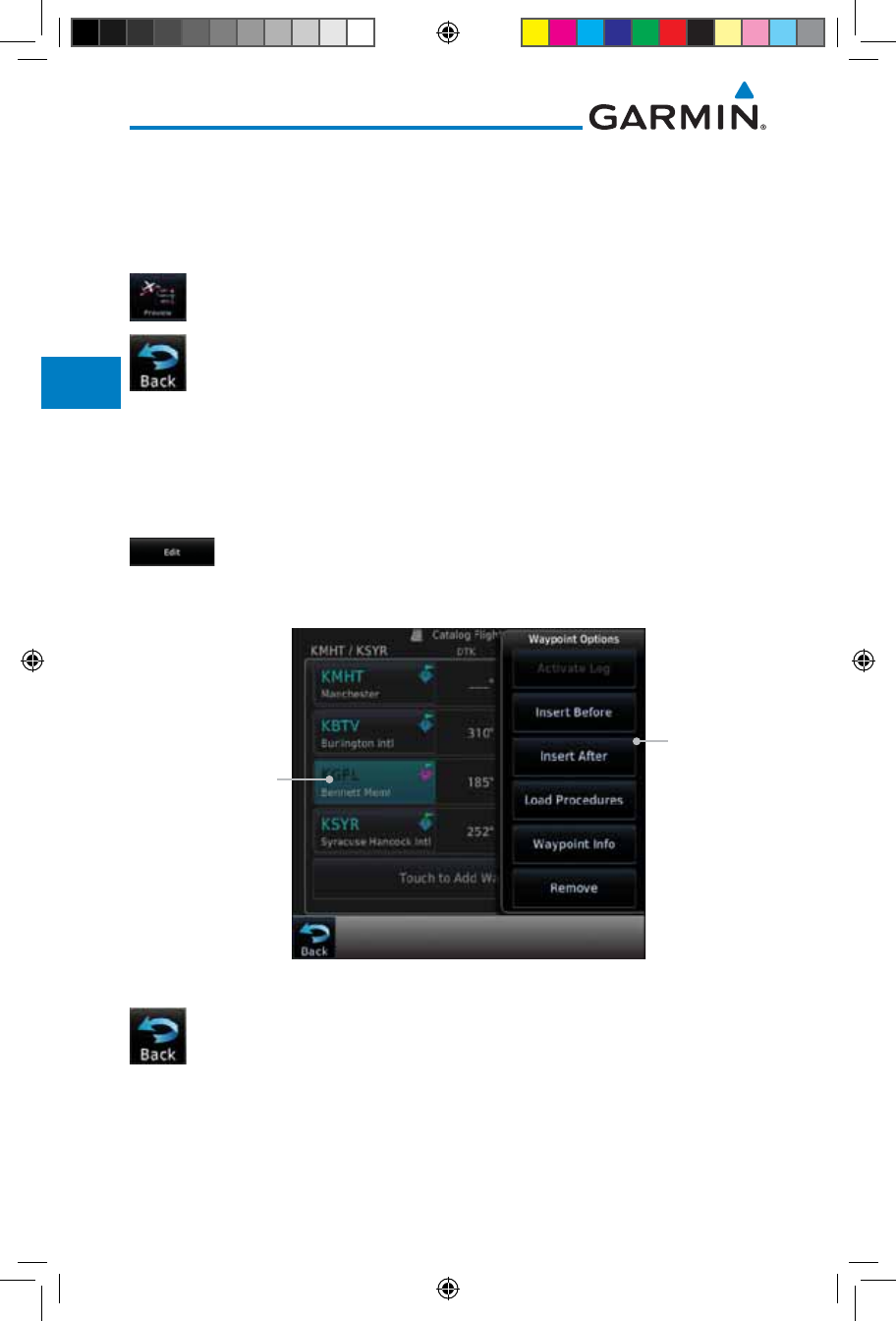
4-34
Garmin GTN 725/750 Pilot’s Guide
190-01007-03 Rev. J
Foreword
Getting
Started
Audio &
Xpdr Ctrl
Com/Nav
FPL
Direct-To
Proc
Charts
Wpt Info
Map
Traffic
Terrain
Weather
Nearest
Services/
Music
Utilities
System
Messages
Symbols
Appendix
Index
4.3.5.3 Catalog Route Option - Preview
1. While viewing the Flight Plan Catalog page, touch the desired
flight plan to select it. The Route Options menu will be
displayed.
2. Touch the Preview key. A map view of the flight plan and
list of the waypoints will be displayed.
3. Touch the Back key to return to the Flight Plan Catalog.
4.3.5.4 Catalog Route Option - Edit
1. While viewing the Flight Plan Catalog page, touch the desired
flight plan to select it. The Route Options menu will be
displayed.
2. Touch the Edit key. The flight plan will be displayed. Make
any changes necessary by touching the desired waypoint and
using the Waypoint Options.
Selected Waypoint
Waypoint
Options List
Figure 4-49 Use Waypoint Options to Edit the Selected Flight Plan
3. Touch the Back key to return to the Flight Plan Catalog.
190-01007-03-Final.indb 34 7/9/2015 2:07:10 PM
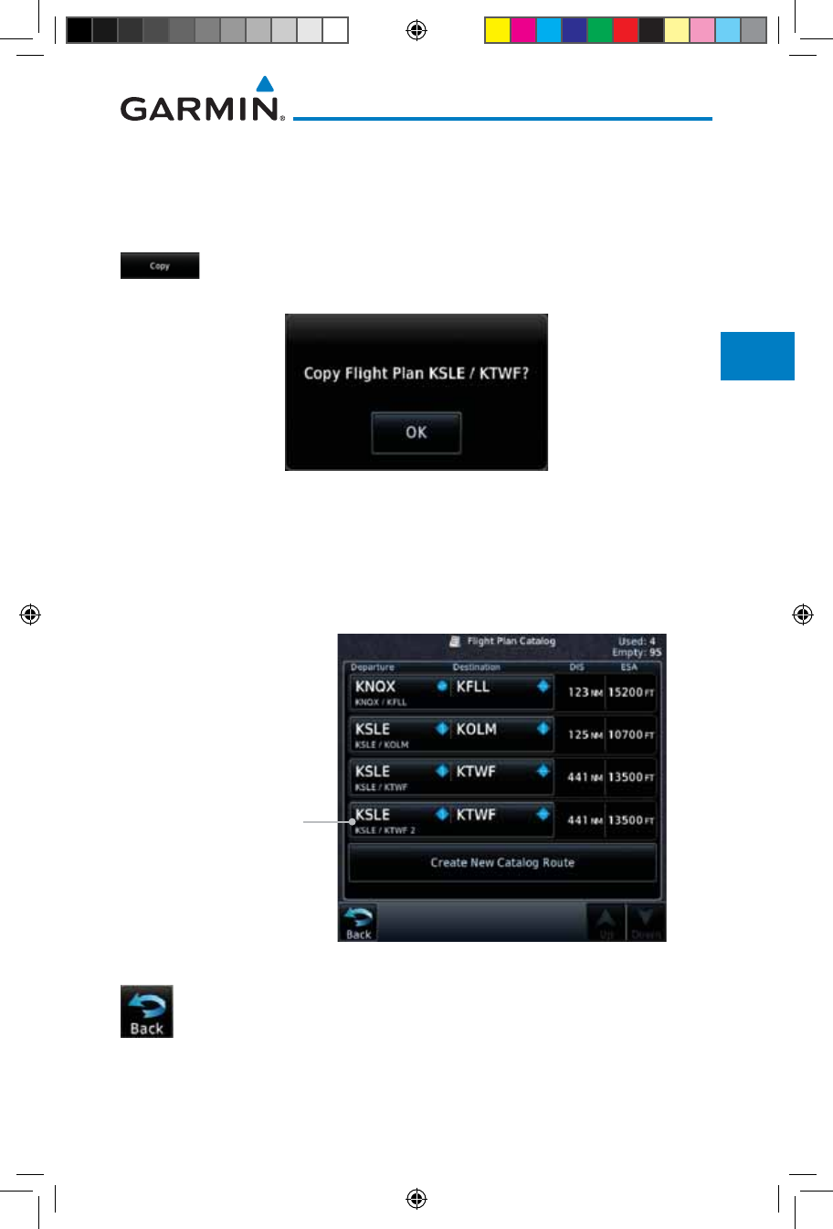
4-35190-01007-03 Rev. J
Garmin GTN 725/750 Pilot’s Guide
Foreword
Getting
Started
Audio &
Xpdr Ctrl
Com/Nav
FPL
Direct-To
Proc
Charts
Wpt Info
Map
Traffic
Terrain
Weather
Nearest
Services/
Music
Utilities
System
Messages
Symbols
Appendix
Index
4.3.5.5 Catalog Route Option - Copy
1. While viewing the Flight Plan Catalog page, touch the desired
flight plan to select it. The Route Options menu will be
displayed.
2. Touch the Copy key. You will be prompted to copy the selected
flight plan.
Figure 4-50 Flight Plan Catalog Route Copy Option
3. A copy of the selected flight plan will now be listed. If any
changes are required for the copy, it can be used as a starting
point for a similar flight plan. Use the Edit Route option to
make the desired changes.
Duplicate Copy Of
Selected Flight Plan
Figure 4-51 Copied Flight Plan
4. Touch the Back key to return to the Active Flight Plan.
190-01007-03-Final.indb 35 7/9/2015 2:07:10 PM
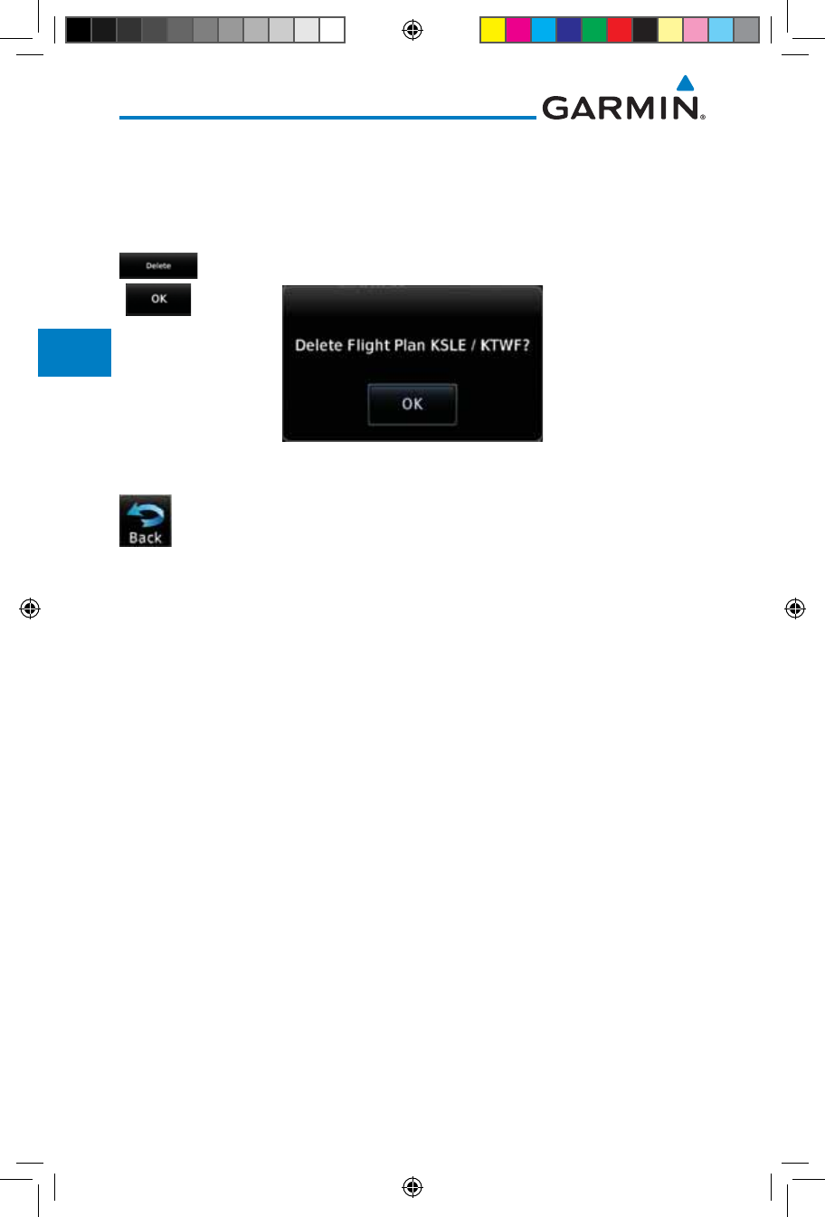
4-36
Garmin GTN 725/750 Pilot’s Guide
190-01007-03 Rev. J
Foreword
Getting
Started
Audio &
Xpdr Ctrl
Com/Nav
FPL
Direct-To
Proc
Charts
Wpt Info
Map
Traffic
Terrain
Weather
Nearest
Services/
Music
Utilities
System
Messages
Symbols
Appendix
Index
4.3.5.6 Catalog Route Option - Delete
1. While viewing the Flight Plan Catalog page, touch the desired
flight plan to select it. The Route Options menu will be
displayed.
2. Touch the Delete key and then touch OK.
Figure 4-52 Delete the Selected Flight Plan from the Catalog
3. Touch the Back key to return to the Active Flight Plan.
190-01007-03-Final.indb 36 7/9/2015 2:07:10 PM
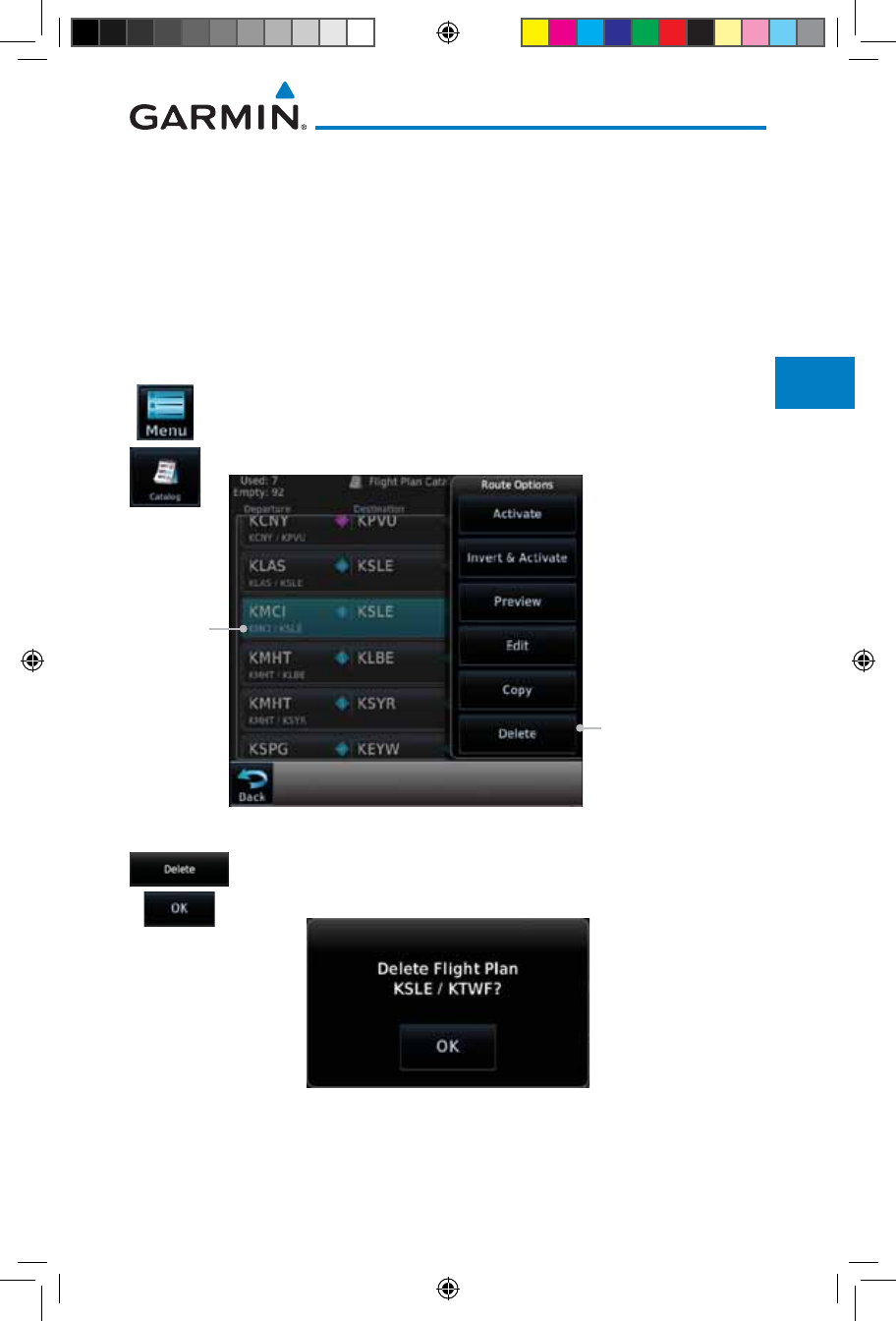
4-37190-01007-03 Rev. J
Garmin GTN 725/750 Pilot’s Guide
Foreword
Getting
Started
Audio &
Xpdr Ctrl
Com/Nav
FPL
Direct-To
Proc
Charts
Wpt Info
Map
Traffic
Terrain
Weather
Nearest
Services/
Music
Utilities
System
Messages
Symbols
Appendix
Index
4.3.6 Delete Flight Plan
There are two methods for deleting a flight plan. Deleting the selected flight
plan from the Catalog using the Route Options completely removes the flight
plan. Deleting the Active Flight Plan using the Delete Flight Plan key on the
Flight Plan menu clears the waypoints from the Active Flight Plan, but does not
remove the flight plan from the Catalog.
4.3.6.1 Delete Flight Plan from Catalog
1. While viewing the Flight Plan page, touch the Menu key, and
then the View Catalog key. The list of currently stored flight
plans will be displayed.
Touch Delete To
Remove The Waypoint
From The Catalog
Selected
Flight Plan
Figure 4-53 Select a Flight Plan from the Catalog
2. Touch the Delete and then the OK key. The selected flight
plan will be removed from the Catalog.
Figure 4-54 Delete a Flight Plan from the Catalog
190-01007-03-Final.indb 37 7/9/2015 2:07:10 PM
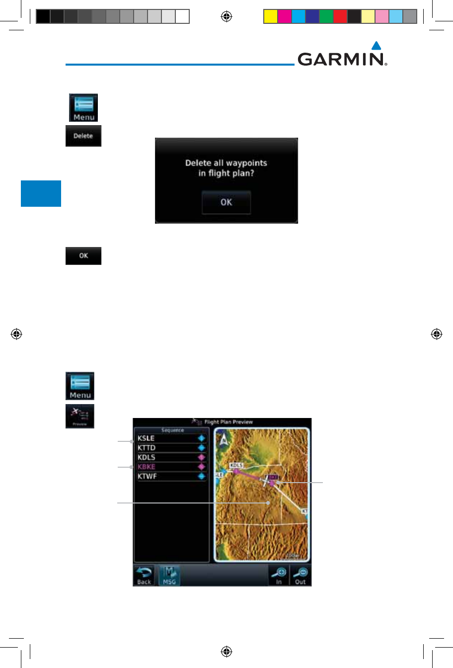
4-38
Garmin GTN 725/750 Pilot’s Guide
190-01007-03 Rev. J
Foreword
Getting
Started
Audio &
Xpdr Ctrl
Com/Nav
FPL
Direct-To
Proc
Charts
Wpt Info
Map
Traffic
Terrain
Weather
Nearest
Services/
Music
Utilities
System
Messages
Symbols
Appendix
Index
4.3.6.2 Delete Active Flight Plan
1. While viewing the Active Flight Plan page, touch the Menu
key, and then the Delete Flight Plan key.
Figure 4-55 Delete a Flight Plan from the Active Flight Plan
2. Touch OK to clear the waypoints from the Active Flight Plan.
The flight plan will not be removed from the Catalog.
4.3.7 Preview Flight Plan
The Preview Flight Plan function provides a summary of a flight plan. A
preview of the Active Flight Plan can be selected from the Flight Plan Menu's
Preview Flight Plan key or selecting a flight plan from the catalog and choosing
Preview from the Route Options menu.
4.3.7.1 Previewing the Active Flight Plan
1. While viewing the Flight Plan page, touch the Menu key, and
then the Preview key. A preview of the Active Flight Plan
will be shown.
Map View
of Flight
Plan Legs
Flight Plan
Waypoint List
Current Aircraft
Position On
Current Leg of
Active Flight Plan
Current Dest
Waypoint
Figure 4-56 Active Flight Plan Preview
190-01007-03-Final.indb 38 7/9/2015 2:07:11 PM
4-39190-01007-03 Rev. J
Garmin GTN 725/750 Pilot’s Guide
Foreword
Getting
Started
Audio &
Xpdr Ctrl
Com/Nav
FPL
Direct-To
Proc
Charts
Wpt Info
Map
Traffic
Terrain
Weather
Nearest
Services/
Music
Utilities
System
Messages
Symbols
Appendix
Index
2. Touch the Back key to return to the Active Flight Plan page.
4.3.7.2 Previewing a Flight Plan in the Catalog
1. While viewing the Flight Plan page, touch the Menu key, and
then the Catalog key. The list of currently stored flight plans
will be displayed.
2. Touch the desired flight plan. The Route Options will now be
displayed.
3. Touch the Preview key to display a preview of the selected
flight plan.
4. Touch the Back key to return to the Flight Plan Catalog.
4.4 Graphically Editing a Flight Plan
The Active Flight Plan may be edited graphically on the Map page. See
Section 9.3.3 for details.
4.5 Import Flight Plans with Connext
When the GTN is interfaced with a compatible Flight Stream device, flight
plans can be wirelessly imported into the GTN from supported Apps (i.e.
Garmin Pilot). The imported flight plans can then be activated or stored to the
flight plan catalog once they are previewed by the pilot.
NOTE: Flight plans over 99 waypoints long are truncated at 99 waypoints
and the last waypoint in the imported/uploaded flight plan may not be the
destination airport.
NOTE:
Flight plan information and user waypoints included as part of a
flight plan will not necessarily retain their names when the flight plan is
transferred from the portable device to the GTN via a Flight Stream device.
Whenever a User Waypoint is imported, it is compared to the existing User
Waypoint catalog. If it matches locations with an existing User Waypoint, the
waypoint will utilize the name saved in the GTN for that waypoint. If there is
not a location match, the waypoint is imported but without the name label
that the import software may have used. Therefore all new User Waypoints
will come in as USR### where the number is the lowest open User Waypoint
slot in the catalog.
190-01007-03-Final.indb 39 7/9/2015 2:07:11 PM
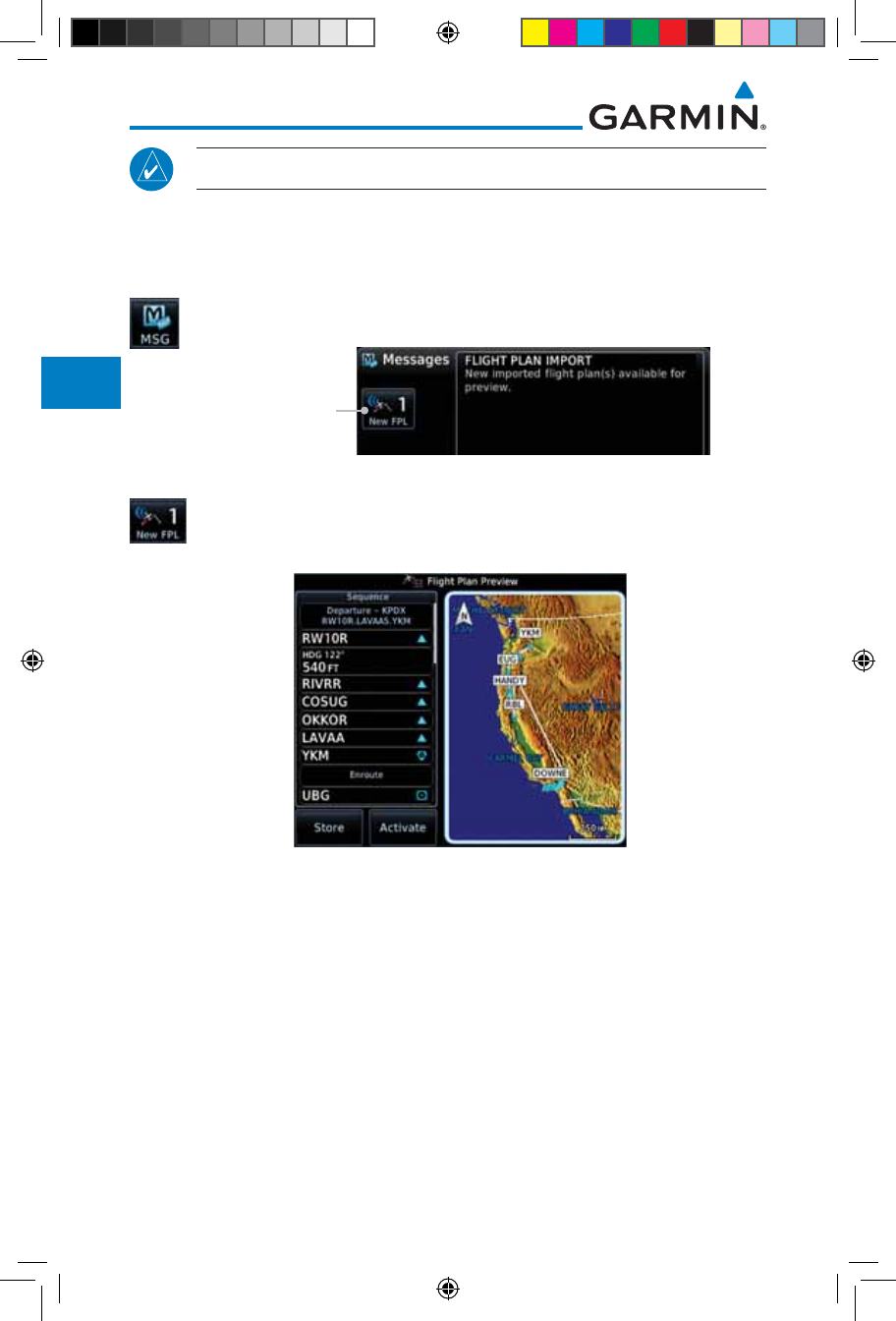
4-40
Garmin GTN 725/750 Pilot’s Guide
190-01007-03 Rev. J
Foreword
Getting
Started
Audio &
Xpdr Ctrl
Com/Nav
FPL
Direct-To
Proc
Charts
Wpt Info
Map
Traffic
Terrain
Weather
Nearest
Services/
Music
Utilities
System
Messages
Symbols
Appendix
Index
NOTE:
This feature is available in software version 5.10 and later.
4.5.1 Operation
On the portable device, select the option to send a flight plan to the GTN.
The GTN MSG key will appear and begin to flash.
1. Pressing the MSG key will open the message page with a
message showing how many flight plans are ready to preview.
Touch To Preview
Flight Plan
Figure 4-57 Flight Plan Import Message
2. Touch the New FPL key to open the flight plan preview page
when only one flight plan is imported, or the flight plan catalog
when more than one flight plan is imported.
Figure 4-58 Preview for Single Flight Plan Import
190-01007-03-Final.indb 40 7/9/2015 2:07:11 PM
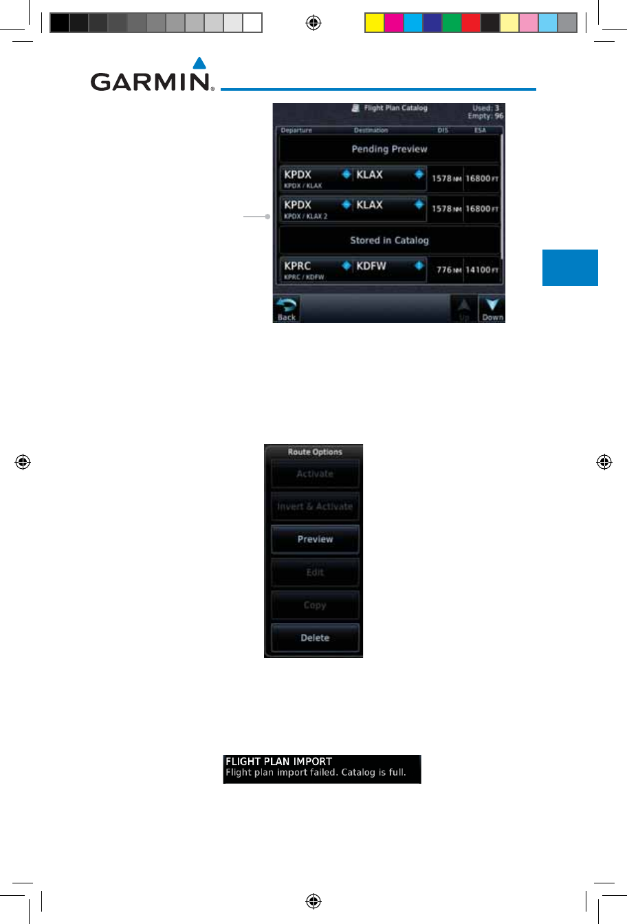
4-41190-01007-03 Rev. J
Garmin GTN 725/750 Pilot’s Guide
Foreword
Getting
Started
Audio &
Xpdr Ctrl
Com/Nav
FPL
Direct-To
Proc
Charts
Wpt Info
Map
Traffic
Terrain
Weather
Nearest
Services/
Music
Utilities
System
Messages
Symbols
Appendix
Index
Touch To Select The
Desired Catalog
Figure 4-59 Catalog for Multiple Flight Plan Import
3. Selecting a flight plan in the catalog that is "Pending Preview"
will slide out a menu to preview or delete the flight plan.
Once the flight plan has been previewed and then stored
or activated, the other Route Options in the menu will be
available.
Figure 4-60 Route Options by Selecting Flight Plan with Pending Review
4.5.2 Potential Errors
If the GTN is unable to import a flight plan due to errors in the flight plan or
a full catalog, the pilot will be alerted with a system message.
Figure 4-61 Flight Plan Import Error Messages
190-01007-03-Final.indb 41 7/9/2015 2:07:11 PM
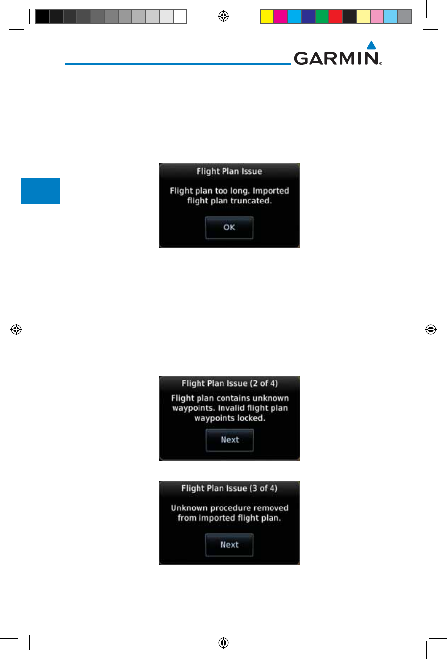
4-42
Garmin GTN 725/750 Pilot’s Guide
190-01007-03 Rev. J
Foreword
Getting
Started
Audio &
Xpdr Ctrl
Com/Nav
FPL
Direct-To
Proc
Charts
Wpt Info
Map
Traffic
Terrain
Weather
Nearest
Services/
Music
Utilities
System
Messages
Symbols
Appendix
Index
If an imported flight plan contains any errors, pop-up messages will be
displayed alerting the pilot of the issues and the resulting changes to the flight
plan.
When the imported flight plan is too long, the GTN will truncate the flight
plan to the correct length. The pilot should be aware that waypoints are missing
from the end of the flight plan, including the destination waypoint.
Figure 4-62 Pop-Up Message Reporting Flight Plan Errors
When the imported flight plan contains waypoints (non-user waypoints),
procedures, or airways that are not found in navigation database, the GTN will
replace those waypoints with locked (lockd) waypoints. These locked waypoints
must be resolved prior to activating the flight plan to provide navigation along
the flight plan.
When more than one error occurs during the flight plan import, the pilot
will need to cycle through the errors by touching the Next key on the pop-up.
Figure 4-63 Pop-Up Message Reporting Unknown Waypoints
Figure 4-64 Pop-Up Message Reporting Unknown Procedure
190-01007-03-Final.indb 42 7/9/2015 2:07:11 PM
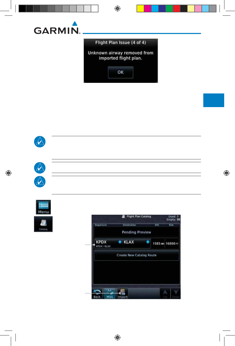
4-43190-01007-03 Rev. J
Garmin GTN 725/750 Pilot’s Guide
Foreword
Getting
Started
Audio &
Xpdr Ctrl
Com/Nav
FPL
Direct-To
Proc
Charts
Wpt Info
Map
Traffic
Terrain
Weather
Nearest
Services/
Music
Utilities
System
Messages
Symbols
Appendix
Index
Figure 4-65 Pop-Up Message Reporting Unknown Airway
4.6 Import Flight Plans with an SD Card
Flight plans can be created on a computer using compatible flight planning
software and saved to the SD card to be imported into the GTN. The imported
flight plans can then be activated or stored to the flight plan catalog once they
are previewed by the pilot.
NOTE: Flight plans over 99 waypoints long are truncated at 99 waypoints
and the last waypoint in the imported/uploaded flight plan may not be the
destination airport.
NOTE:
This feature is available in software version 5.10 and later.
NOTE:
The flight plan file format used by the GTN is different than the file
format used by the GNS 400W/500W Series navigators.
1. While viewing the Flight Plan page, touch the Menu key and
then the Catalog key to display the Flight Plan Catalog.
Flight Plan
On SD Card
Touch To Import
Flight Plan
Figure 4-66 Catalog for SD Card Flight Plan Import
190-01007-03-Final.indb 43 7/9/2015 2:07:12 PM
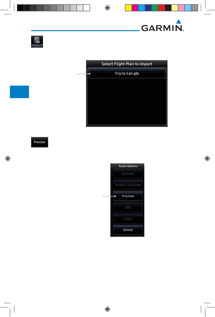
4-44
Garmin GTN 725/750 Pilot’s Guide
190-01007-03 Rev. J
Foreword
Getting
Started
Audio &
Xpdr Ctrl
Com/Nav
FPL
Direct-To
Proc
Charts
Wpt Info
Map
Traffic
Terrain
Weather
Nearest
Services/
Music
Utilities
System
Messages
Symbols
Appendix
Index
2. An Import key will be present in the menu bar when flight
plans are present on the SD card. Touch the Import key to
open a pop-up with a list of the file names of the flight plans
on the SD card.
Touch To Import
Flight Plan From
SD Card
Figure 4-67 Flight Plan To Import From SD Card
3. After selecting the desired flight plan to import, the GTN will
attempt to import the flight plan and open the Route Options
slide out menu. The imported flight plan must be previewed
before being activated. Touch Preview to view the flight plan.
Touch To Preview
Flight Plan From
SD Card
Figure 4-68 Route Options For SD Card Flight Plan Import
190-01007-03-Final.indb 44 7/9/2015 2:07:12 PM
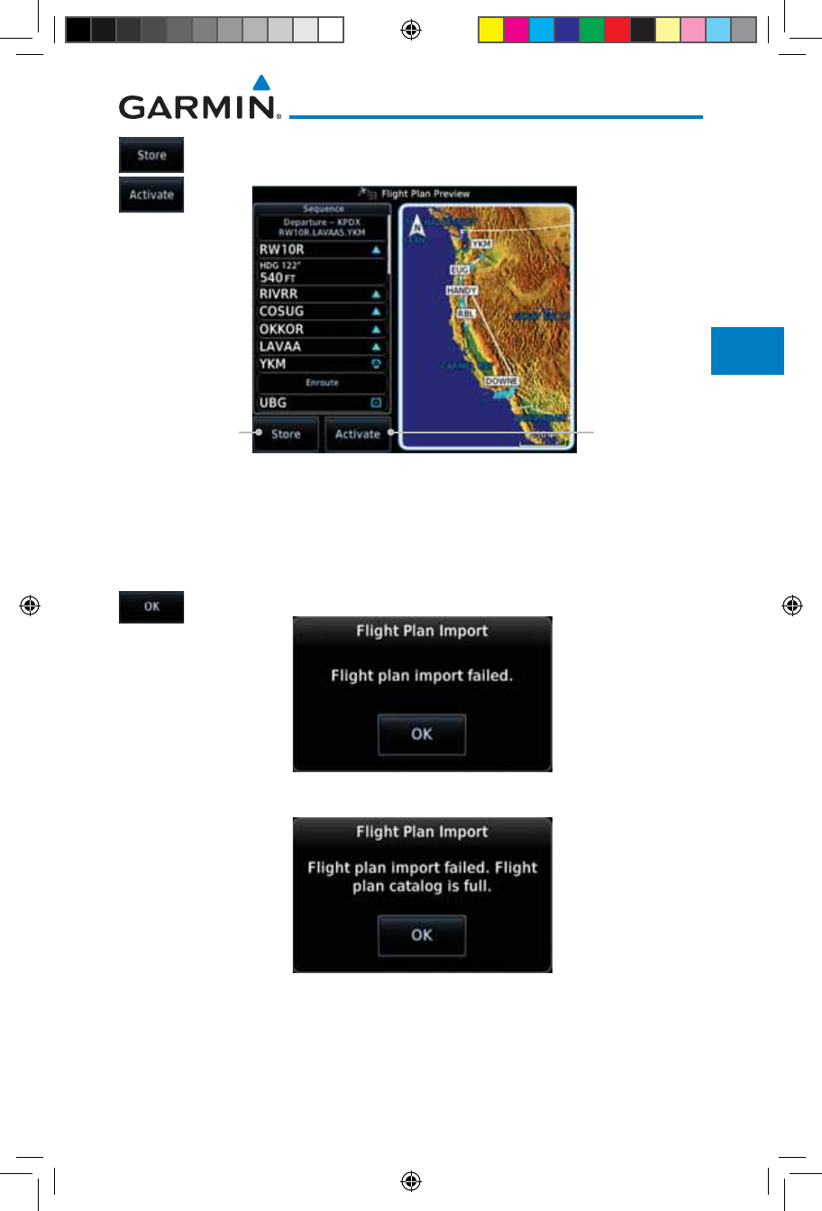
4-45190-01007-03 Rev. J
Garmin GTN 725/750 Pilot’s Guide
Foreword
Getting
Started
Audio &
Xpdr Ctrl
Com/Nav
FPL
Direct-To
Proc
Charts
Wpt Info
Map
Traffic
Terrain
Weather
Nearest
Services/
Music
Utilities
System
Messages
Symbols
Appendix
Index
4. Press Store to save the flight plan to the catalog. Press
Activate to make the imported flight plan the active route.
Touch To Store To
Save Flight Plan
To The Catalog
Touch To Make
The Imported
Flight Plan The
Active Route
Figure 4-69 Route Options For SD Card Flight Plan Import
4.6.1 Potential Errors
If the GTN is unable to import a flight plan due to errors in the flight plan or
a full catalog, the pilot will immediately be alerted with a pop-up.
1. Touch OK at the prompt to continue.
Figure 4-70 Flight Plan Import Fault
Figure 4-71 Flight Plan Import Fault - Catalog Full
190-01007-03-Final.indb 45 7/9/2015 2:07:12 PM
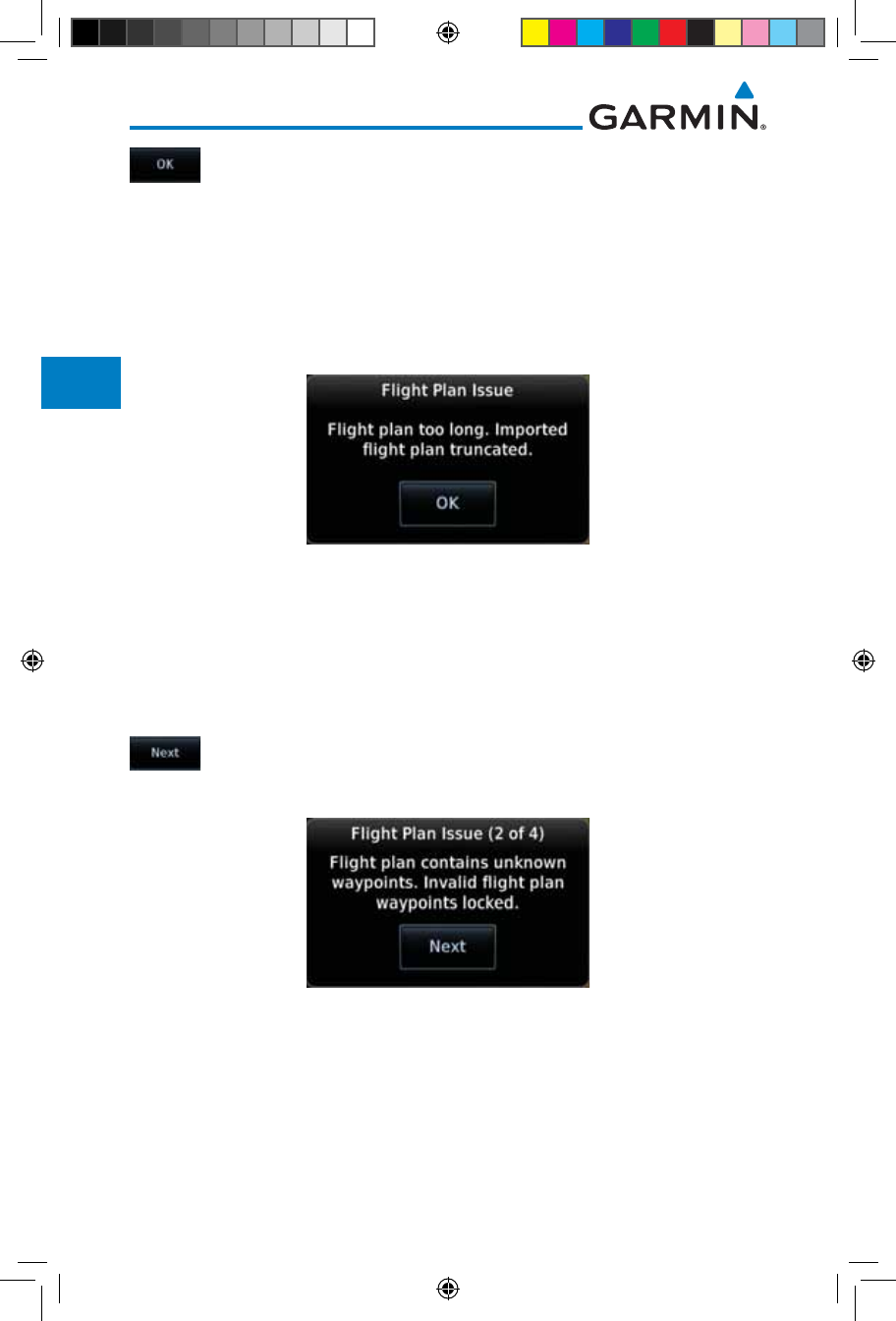
4-46
Garmin GTN 725/750 Pilot’s Guide
190-01007-03 Rev. J
Foreword
Getting
Started
Audio &
Xpdr Ctrl
Com/Nav
FPL
Direct-To
Proc
Charts
Wpt Info
Map
Traffic
Terrain
Weather
Nearest
Services/
Music
Utilities
System
Messages
Symbols
Appendix
Index
2. If an imported flight plan contains any errors, pop-up
messages will be displayed alerting the pilot of the issues
and the resulting changes to the flight plan. These pop-ups
are presented the first time that the flight plan is viewed on
the Flight Plan Preview page.
When the imported flight plan is too long, the GTN will truncate
the flight plan to the correct length. The pilot should be aware
that waypoints are missing from the end of the flight plan.
Figure 4-72 Flight Plan Import Issue - Flight Plan Too Long
3. When the imported flight plan contains waypoints (non-user
waypoints), procedures, or airways that are not found in
navigation database, the GTN will replace those waypoints
with locked waypoints. These locked waypoints must be
resolved prior to activating the flight plan.
When more than one error occurs during the flight plan import,
the pilot will need to cycle through the errors by touching the
Next key on the pop-up.
Figure 4-73 Flight Plan Import Issue - Flight Plan Contains Unknown Waypoints
190-01007-03-Final.indb 46 7/9/2015 2:07:12 PM
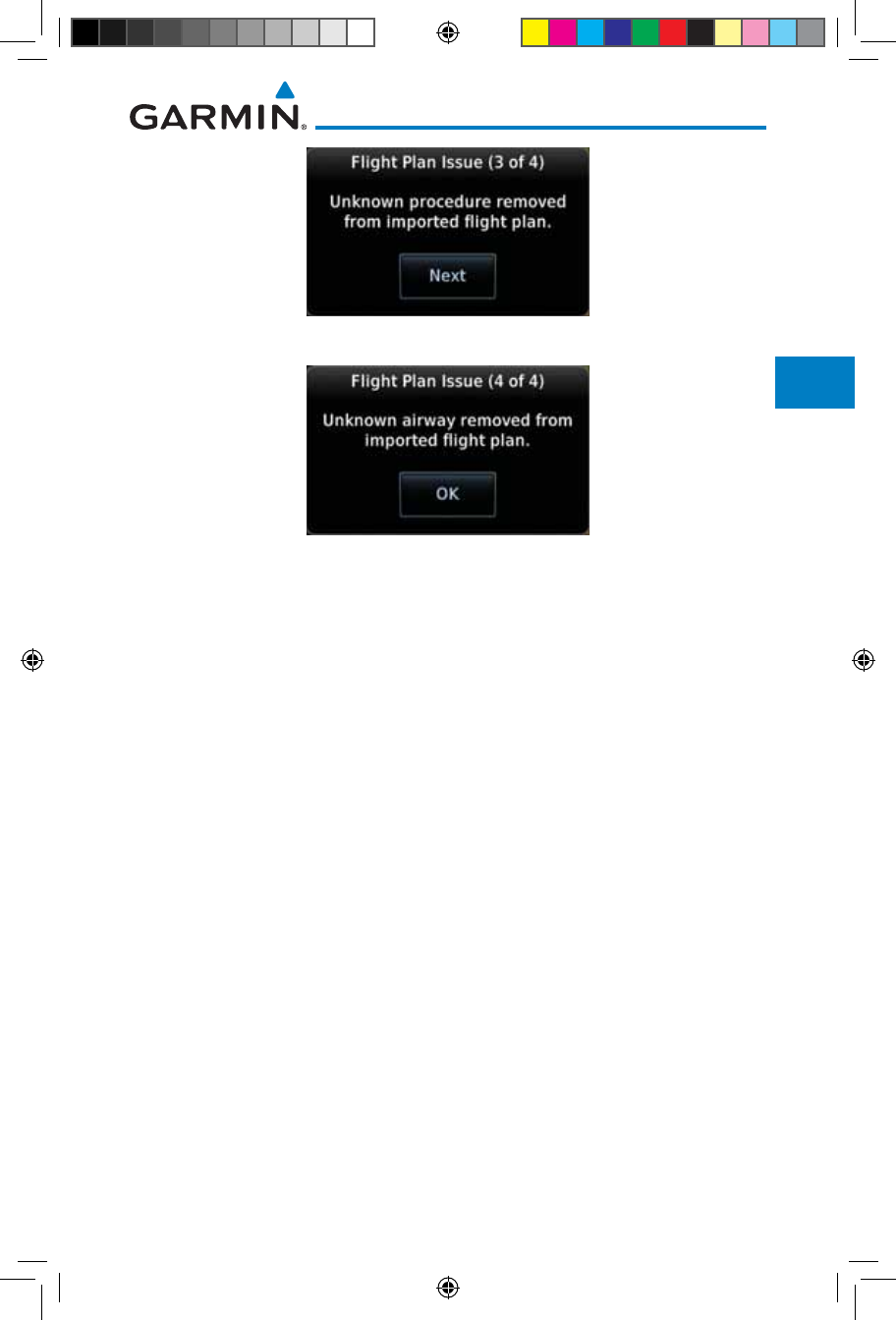
4-47190-01007-03 Rev. J
Garmin GTN 725/750 Pilot’s Guide
Foreword
Getting
Started
Audio &
Xpdr Ctrl
Com/Nav
FPL
Direct-To
Proc
Charts
Wpt Info
Map
Traffic
Terrain
Weather
Nearest
Services/
Music
Utilities
System
Messages
Symbols
Appendix
Index
Figure 4-74 Flight Plan Import Issue - Unknown Procedure Removed From Flight Plan
Figure 4-75 Flight Plan Import Issue - Unknown Airway Removed From Flight Plan
190-01007-03-Final.indb 47 7/9/2015 2:07:12 PM

4-48
Garmin GTN 725/750 Pilot’s Guide
190-01007-03 Rev. J
Foreword
Getting
Started
Audio &
Xpdr Ctrl
Com/Nav
FPL
Direct-To
Proc
Charts
Wpt Info
Map
Traffic
Terrain
Weather
Nearest
Services/
Music
Utilities
System
Messages
Symbols
Appendix
Index
This page intentionally left blank
190-01007-03-Final.indb 48 7/9/2015 2:07:12 PM
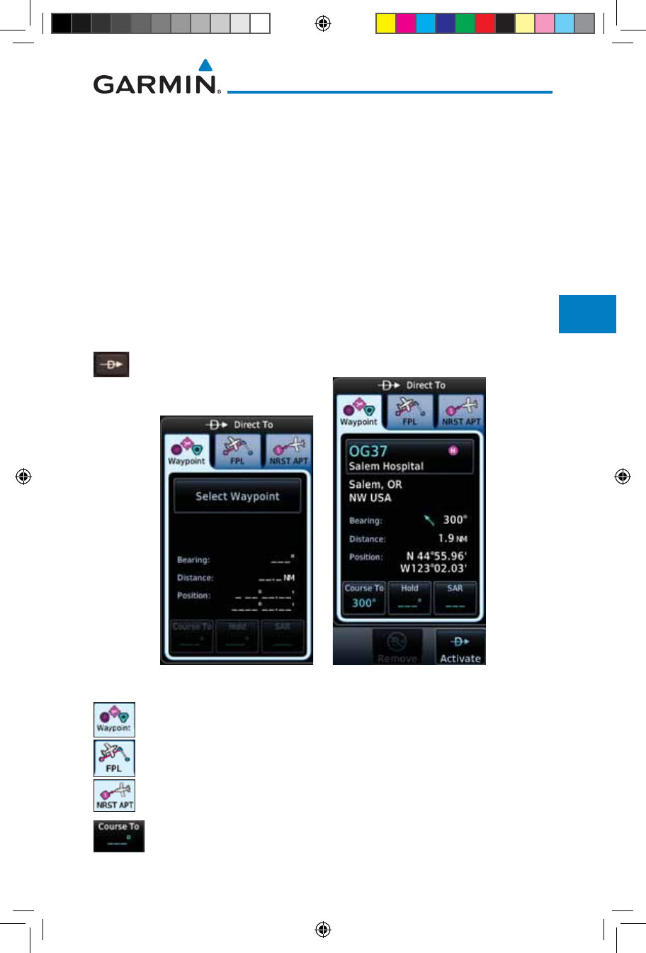
5-1190-01007-03 Rev. J
Garmin GTN 725/750 Pilot’s Guide
Foreword
Getting
Started
Audio &
Xpdr Ctrl
Com/Nav
FPL
Direct-To
Proc
Charts
Wpt Info
Map
Traffic
Terrain
Weather
Nearest
Services/
Music
Utilities
System
Messages
Symbols
Appendix
Index
5 DIRECT-TO
The GTN 7XX Direct-To function can quickly set a course to any waypoint.
If the pilot selects Direct-To to a waypoint that is in the flight plan, waypoint
sequencing in the flight plan will resume upon reaching that waypoint. If the
pilot selects Direct-To for a waypoint that is not in the flight plan, the flight
plan will no longer be active but remains available. There are some fixes within
procedures for which if a Direct-To is selected then the approach will not be
active. For example, if you activate a Direct-To course to a waypoint between
the FAF and the MAP and go Direct-To to that waypoint then approach guidance
will not become active.
5.1 Direct-To Navigation
1. Press the Direct-To key on the right side of the unit.
Figure 5-1 Direct-To Wpt Page
2. Select Waypoint, FPL, or NRST APT from the Direct-To
window by touching the desired tab.
3. If a specific course is desired, touch the Course To key.
190-01007-03-Final.indb 1 7/9/2015 2:07:13 PM
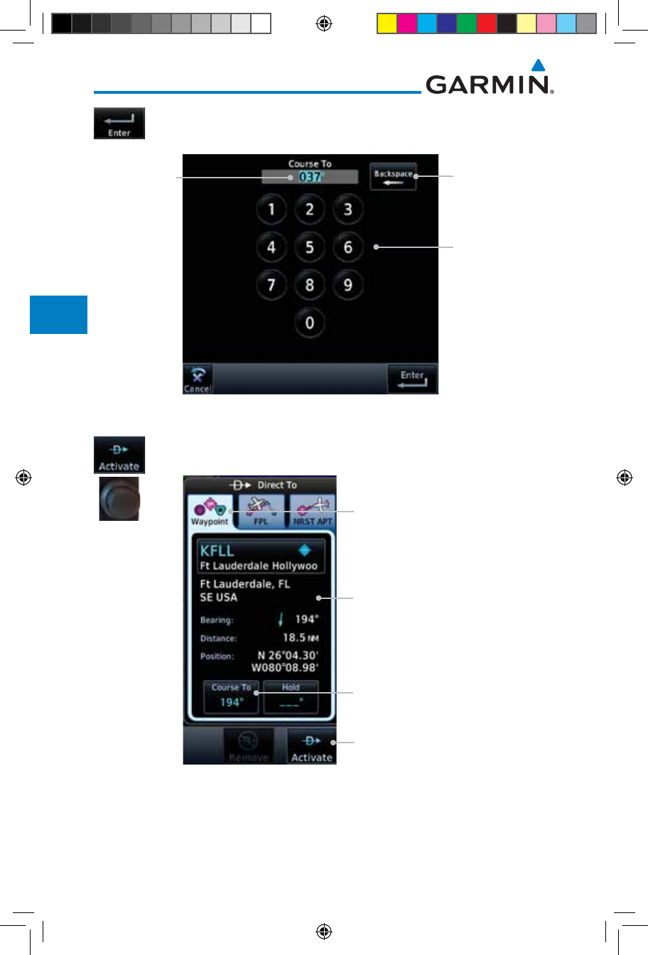
5-2
Garmin GTN 725/750 Pilot’s Guide
190-01007-03 Rev. J
Foreword
Getting
Started
Audio &
Xpdr Ctrl
Com/Nav
FPL
Direct-To
Proc
Charts
Wpt Info
Map
Traffic
Terrain
Weather
Nearest
Services/
Music
Utilities
System
Messages
Symbols
Appendix
Index
4. Use the numeric keypad to select the course and then touch
the Enter key.
Numeric
Keypad
Selected
Course
Backspace
Key
Figure 5-2 Direct-To Course Selection
5. Touch the desired waypoint and touch the Activate key or
press the small right knob.
Touch To Activate
Direct-To This Waypoint
Waypoint Detail
Waypoint Tab
Touch To Select
A Specific Course
Figure 5-3 Direct-To Selection
6. The Map page will now be displayed with the new Direct-To
course.
190-01007-03-Final.indb 2 7/9/2015 2:07:13 PM
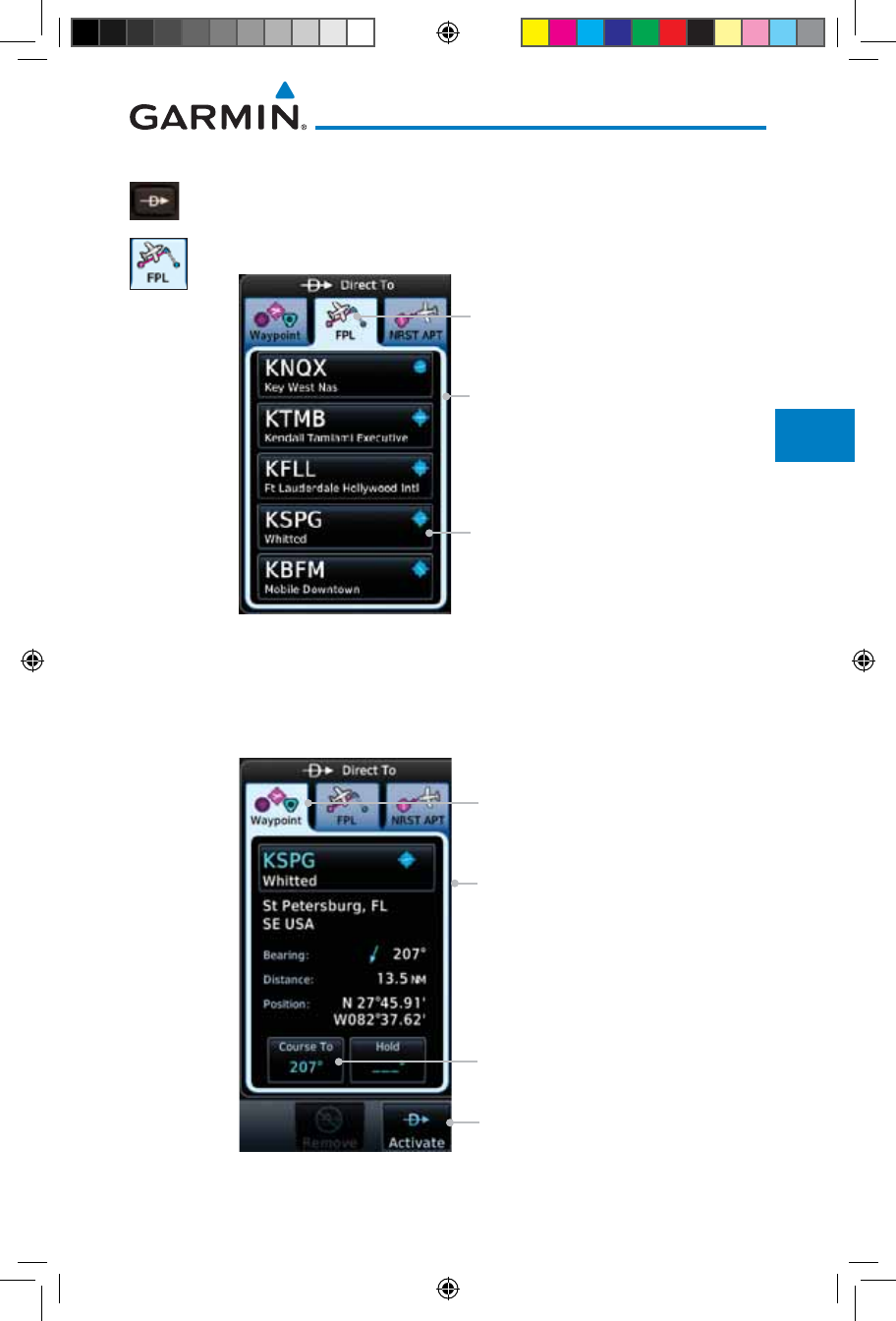
5-3190-01007-03 Rev. J
Garmin GTN 725/750 Pilot’s Guide
Foreword
Getting
Started
Audio &
Xpdr Ctrl
Com/Nav
FPL
Direct-To
Proc
Charts
Wpt Info
Map
Traffic
Terrain
Weather
Nearest
Services/
Music
Utilities
System
Messages
Symbols
Appendix
Index
5.2 Direct-To a Flight Plan Waypoint
1. Press the Direct-To key on the right side of the unit.
2. Touch the FPL tab at the top of the Direct-To window.
Touch Waypoint
Key To Select
Flight Plan Waypoint List
Flight Plan Tab
Figure 5-4 Direct-To Flight Plan Leg Selection
3. Touch the flight plan waypoint you want to navigate directly to. The
Direct-To Waypoint page will display information about the selected
flight plan waypoint.
Touch To Activate
Direct-To This Waypoint
Waypoint Detail
Waypoint Tab
Touch To Select
A Specific Course
Figure 5-5 Selected Direct-To Flight Plan Leg
190-01007-03-Final.indb 3 7/9/2015 2:07:13 PM
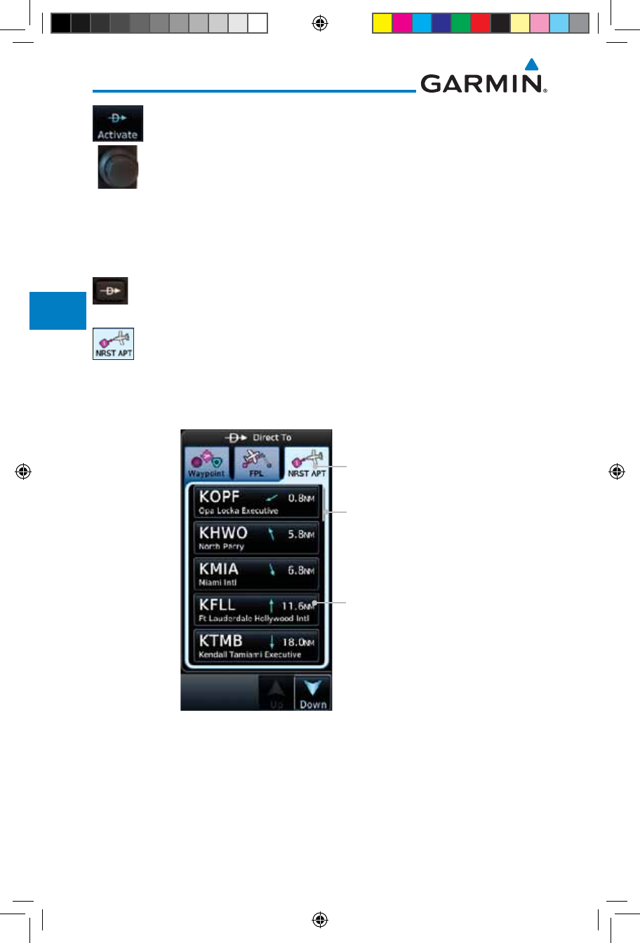
5-4
Garmin GTN 725/750 Pilot’s Guide
190-01007-03 Rev. J
Foreword
Getting
Started
Audio &
Xpdr Ctrl
Com/Nav
FPL
Direct-To
Proc
Charts
Wpt Info
Map
Traffic
Terrain
Weather
Nearest
Services/
Music
Utilities
System
Messages
Symbols
Appendix
Index
4. Touch the Activate key or press the small right knob to
activate the selection.
5. The Map page will now be displayed with the new Direct-To
course.
5.3 Direct-To a Nearest Airport
1. Press the Direct-To key on the lower right side of the unit.
2. Touch the NRST APT tab at the top of the Direct-To window.
The nearest 25 airports within 200 NM will be listed. The
airport at the top of the list is the nearest airport. To review
the other nearest airports, touch the Up and Down keys to
scroll through the list.
Touch List And Drag
Finger To Scroll List
Nearest Airport List
Nearest Tab
Figure 5-6 Direct-To Nearest Airport Selection
190-01007-03-Final.indb 4 7/9/2015 2:07:13 PM
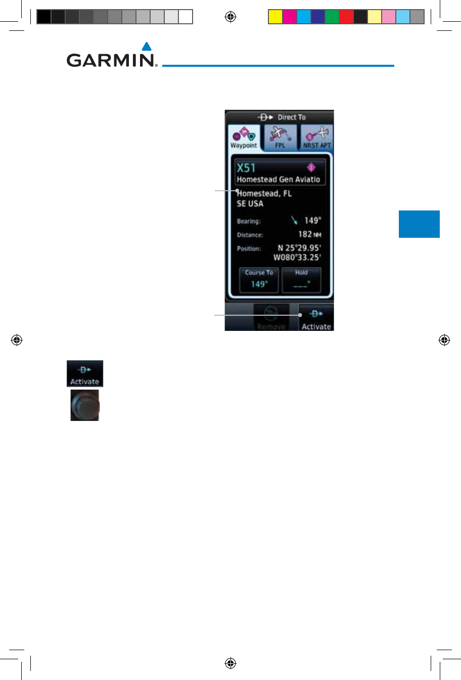
5-5190-01007-03 Rev. J
Garmin GTN 725/750 Pilot’s Guide
Foreword
Getting
Started
Audio &
Xpdr Ctrl
Com/Nav
FPL
Direct-To
Proc
Charts
Wpt Info
Map
Traffic
Terrain
Weather
Nearest
Services/
Music
Utilities
System
Messages
Symbols
Appendix
Index
3. Touch the desired airport to select it. The selected airport will
be displayed in the Waypoint page.
Activate Direct-To
Course
Direct-To Waypoint
Figure 5-7 Selected Direct-To Nearest Airport
4. Touch the Activate key or press the small right knob to
activate the selection.
5. The Map page will now be displayed with the new Direct-To
course.
190-01007-03-Final.indb 5 7/9/2015 2:07:14 PM
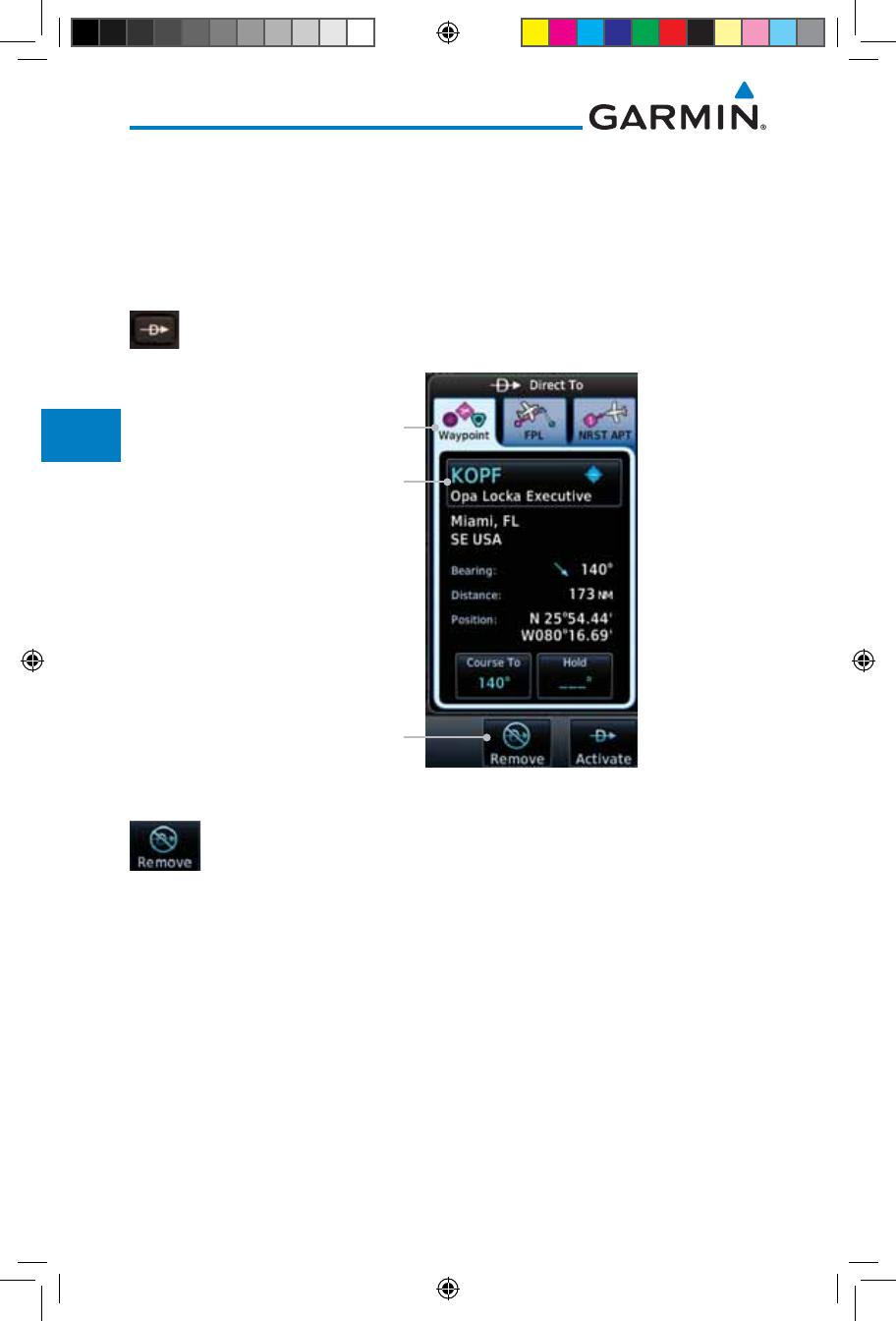
5-6
Garmin GTN 725/750 Pilot’s Guide
190-01007-03 Rev. J
Foreword
Getting
Started
Audio &
Xpdr Ctrl
Com/Nav
FPL
Direct-To
Proc
Charts
Wpt Info
Map
Traffic
Terrain
Weather
Nearest
Services/
Music
Utilities
System
Messages
Symbols
Appendix
Index
5.4 Removing a Direct-To Course
When a Direct-To course is cancelled, the previously active flight plan will be
reactivated and the nearest leg to the aircraft position will become the active leg.
If there was no active flight plan, after cancelling the Direct-To course the aircraft
will continue with the current heading.
1. Press the Direct-To key to display the Direct-To page.
Touch To Remove
(Cancel) The
Direct-To Course
Direct-To Waypoint
Waypoint Tab
Figure 5-8 Cancel the Direct-To Course
2. Touch the Remove key.
3. Navigation will now return to the active flight plan.
190-01007-03-Final.indb 6 7/9/2015 2:07:14 PM
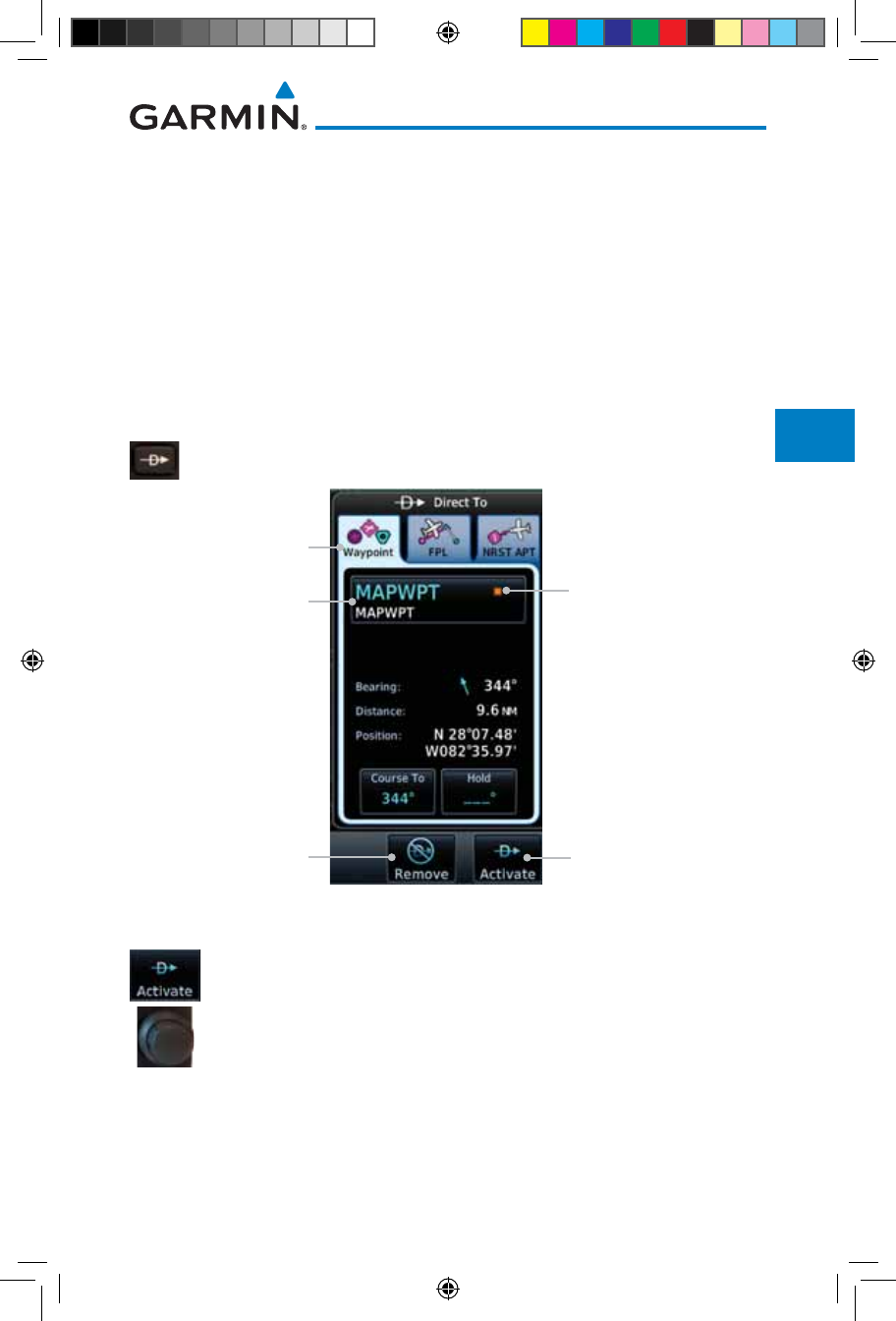
5-7190-01007-03 Rev. J
Garmin GTN 725/750 Pilot’s Guide
Foreword
Getting
Started
Audio &
Xpdr Ctrl
Com/Nav
FPL
Direct-To
Proc
Charts
Wpt Info
Map
Traffic
Terrain
Weather
Nearest
Services/
Music
Utilities
System
Messages
Symbols
Appendix
Index
5.5 Direct-To Map Waypoint
A Direct-To course may be set to any waypoint selected on the Map page. The
waypoint is selected by touching an item such as an airport, VOR, or NDB or
any other location. Touching the map page at any place not having an existing
location name will create a waypoint with the name “MAPWPT.” Touching the
Direct-To key will automatically insert the selected waypoint as the Direct-To
waypoint. The MAPWPT will be saved as a User Waypoint.
1. On the Map page, touch the map at the location intended to
be the Direct-To waypoint.
2. Press the Direct-To key on the right side of the unit.
Touch To
Remove The
Direct-To Course
Direct-To
Waypoint Name
Waypoint Tab
Touch To
Activate The
Direct-To Course
Direct-To Waypoint
Map Symbol
Figure 5-9 Touch the Map to Create a MAPWPT as the Direct-To Course Destination
3. Touch the Activate key or press the small right knob to
activate the selection.
190-01007-03-Final.indb 7 7/9/2015 2:07:14 PM
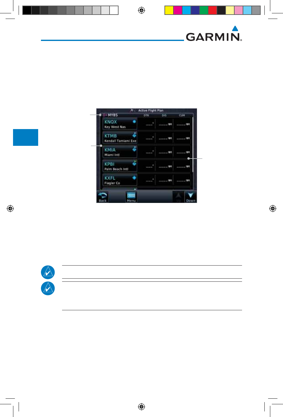
5-8
Garmin GTN 725/750 Pilot’s Guide
190-01007-03 Rev. J
Foreword
Getting
Started
Audio &
Xpdr Ctrl
Com/Nav
FPL
Direct-To
Proc
Charts
Wpt Info
Map
Traffic
Terrain
Weather
Nearest
Services/
Music
Utilities
System
Messages
Symbols
Appendix
Index
5.6 Off-Route Direct-To Course
An off-route Direct-To course may be selected by using the Waypoint tab,
Nrst Apt tab, or selecting a waypoint on the map. When an off-route Direct-
To course is activated, the existing active flight plan will be deactivated. The
original active flight plan and waypoint sequencing is reactivated when the
Direct-To course is removed.
Direct-To Waypoint
Flight Plan Data
Is Cleared
Flight Plan
Waypoint List
Figure 5-10 Active Flight Data is Removed When a Direct-To Course is Activated
5.7 Graphically Editing a Direct-To Route
Direct-To routes may be edited graphically on the Map page the same as a
regular flight plan. See Section 9.3.3 for details.
5.8 Direct-To a User-Defined Hold
NOTE: This feature is available in software version 6.00 and later.
NOTE: Any time a user hold is changed with the Direct-To key, upon
pressing the "Activate the Direct-To Hold" key, navigation guidance will
be given back to the holding fix and the new hold re-initiated.
A user-defined hold can be created as part of a Direct-To to any waypoint.
Automatic waypoint sequencing will be suspended during the hold.
190-01007-03-Final.indb 8 7/9/2015 2:07:14 PM
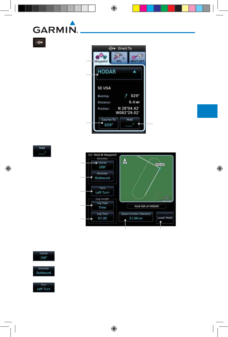
5-9190-01007-03 Rev. J
Garmin GTN 725/750 Pilot’s Guide
Foreword
Getting
Started
Audio &
Xpdr Ctrl
Com/Nav
FPL
Direct-To
Proc
Charts
Wpt Info
Map
Traffic
Terrain
Weather
Nearest
Services/
Music
Utilities
System
Messages
Symbols
Appendix
Index
1. Press the Direct-To key to display the Direct-To page.
Touch To Select A
Specific Course
Direct-To
Waypoint Name
Waypoint Tab
Touch To Create
A Hold At
Direct-To Wpt
Figure 5-11 Create Hold at Direct-To Waypoint
2. Touch the Hold key. The Direct-To Hold page is displayed.
Touch To Select A
Specific Course
Touch To Select
Course Direction
Touch To Select
Turn Direction
Touch To Select
Leg Length Type
Touch To Select
Leg Length Time
Touch To Select EFC Time Touch To Accept Hold
Parameters
Figure 5-12 Entering Direct-To Hold Parameters
3. Touch the Course key to open the keypad. Use the keypad
and the Enter key to select the inbound or outbound course.
4. Touch the Course Direction key to select between Inbound
or Outbound for the course direction.
5. Touch the Turn key to select between Left or Right for the turn
direction.
190-01007-03-Final.indb 9 7/9/2015 2:07:14 PM

5-10
Garmin GTN 725/750 Pilot’s Guide
190-01007-03 Rev. J
Foreword
Getting
Started
Audio &
Xpdr Ctrl
Com/Nav
FPL
Direct-To
Proc
Charts
Wpt Info
Map
Traffic
Terrain
Weather
Nearest
Services/
Music
Utilities
System
Messages
Symbols
Appendix
Index
6. Touch the Leg Type key to select between Time or Distance
for the leg type.
7. Touch the Leg Time or Leg Distance key to display the
keypad. Use the keypad and the Enter key to select the length
of the leg.
8. Touch the Expect Further Clearance key to display the
keypad. Use the keypad and the Enter key to select the time
for a reminder.
9. Touch the Load Hold key to accept the hold parameters and
return to the Direct-To page.
Specified Course
To Direct-To Wpt
Touch To Activate
The Direct-To
Course And Hold
Hold Pattern Course
Figure 5-13 Direct-To Page with Hold Selected
10. Touch the Hold Activate key or press the small right knob
to activate the selection.
190-01007-03-Final.indb 10 7/9/2015 2:07:15 PM
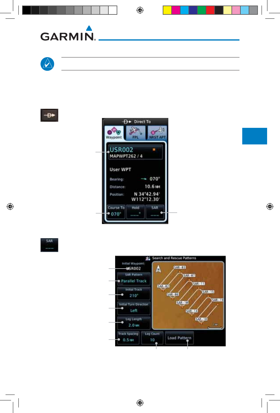
5-11190-01007-03 Rev. J
Garmin GTN 725/750 Pilot’s Guide
Foreword
Getting
Started
Audio &
Xpdr Ctrl
Com/Nav
FPL
Direct-To
Proc
Charts
Wpt Info
Map
Traffic
Terrain
Weather
Nearest
Services/
Music
Utilities
System
Messages
Symbols
Appendix
Index
5.9 Direct-To a Search and Rescue Pattern
NOTE: This feature is available in software version 6.00 and later.
A search and rescue pattern can be created as part of a Direct-To for a flight
plan, off-route, or map waypoint. Creating a SAR pattern as part of an an off-
route Direct-To will insert the SAR pattern waypoints at the end of the En Route
portion of the active flight plan.
1. Press the Direct-To key to display the Direct-To page.
Touch To Select A
Specific Course
Touch To Create SAR
Pattern At Direct-To Wpt
Direct-To Wpt
Figure 5-14 Create SAR Pattern at Direct-To Waypoint
2. Touch the SAR key. The Direct-To Search and Rescue Patterns
page is displayed.
Selected Initial Wpt
Touch To Select Desired
SAR Pattern
Touch To Select Initial Track
Touch To Select
Initial Turn Direction
Touch To Select Track
Spacing Distance
Touch To Select Number
Of Legs
Touch To Load Selected
SAR Pattern to Direct-To
Touch To Select Leg Length
Figure 5-15 Direct-To Search and Rescue Pattern Page
190-01007-03-Final.indb 11 7/9/2015 2:07:15 PM
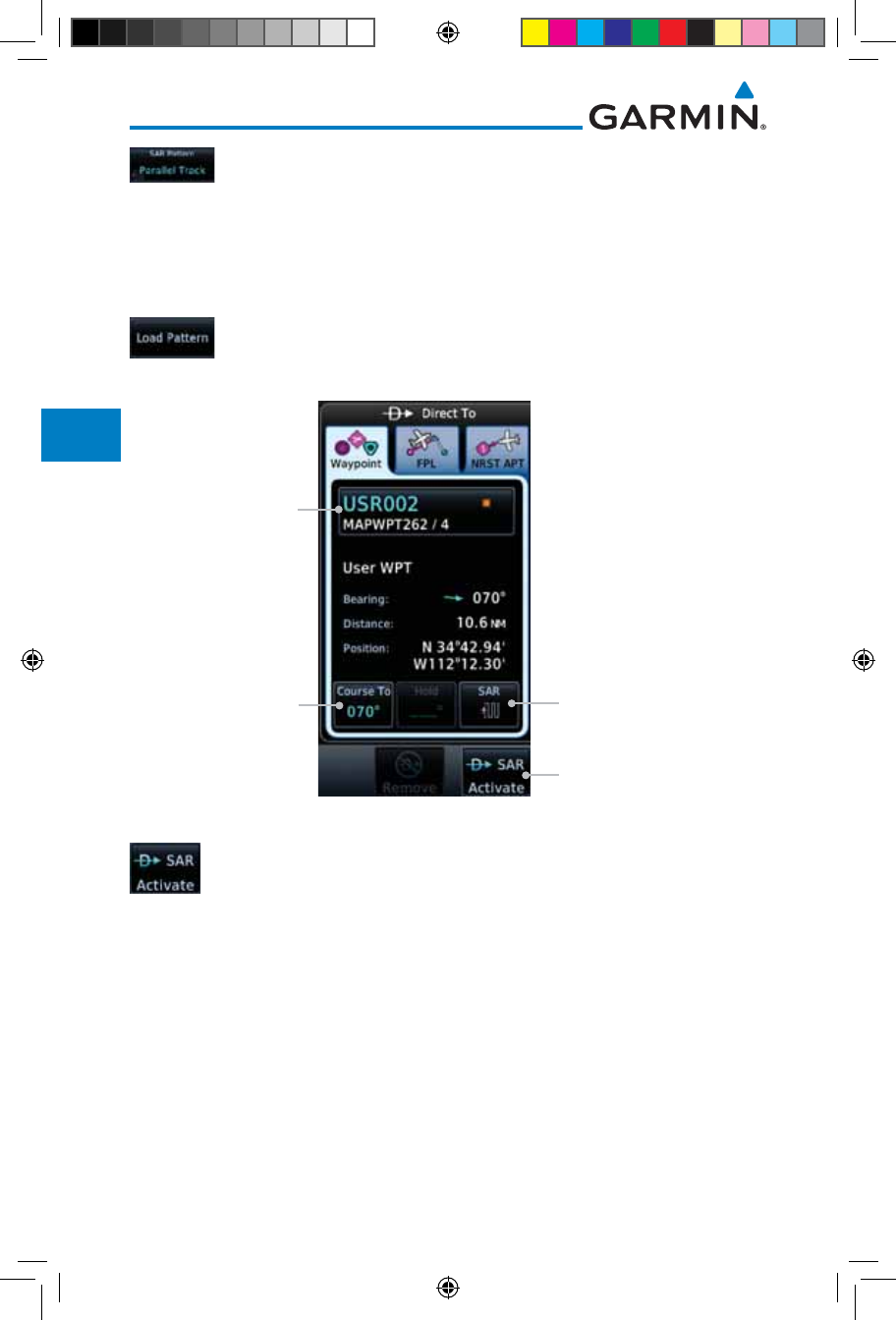
5-12
Garmin GTN 725/750 Pilot’s Guide
190-01007-03 Rev. J
Foreword
Getting
Started
Audio &
Xpdr Ctrl
Com/Nav
FPL
Direct-To
Proc
Charts
Wpt Info
Map
Traffic
Terrain
Weather
Nearest
Services/
Music
Utilities
System
Messages
Symbols
Appendix
Index
3. Touch the SAR Pattern key to select between Parallel Track,
Sector Search, Expanding Square, or Orbit for the SAR pattern
type. The available patterns can be configured by the installer
and all of the listed pattern types may not be available. See
the Section 4.2.4 Load Search and Rescue Pattern for more
details on configuring each pattern type.
4. Confirm the SAR pattern information and then touch the Load
Pattern key to accept the SAR parameters and return to the
Direct-To page.
Specified Course
To Direct-To Wpt Selected SAR Pattern Type
Direct-To Wpt
Touch To Activate Direct-To
Course And SAR Pattern
Figure 5-16 Direct-To Page with SAR Pattern Selected
5. Touch the SAR Activate key or press the small right knob
to activate the selection.
190-01007-03-Final.indb 12 7/9/2015 2:07:15 PM
6-1190-01007-03 Rev. J
Garmin GTN 725/750 Pilot’s Guide
Foreword
Getting
Started
Audio &
Xpdr Ctrl
Com/Nav
FPL
Direct-To
Proc
Charts
Wpt Info
Map
Traffic
Terrain
Weather
Nearest
Services/
Music
Utilities
System
Messages
Symbols
Appendix
Index
6 PROCEDURES
The GTN 7XX allows you to fly non-precision and precision approaches to
airports with published instrument approach procedures. All available approaches
are stored on your Jeppesen NavData
®
card, and are automatically updated when
the card’s files have been updated. Approach procedures are not the same as the
approach plates available in ChartView, which is a separate database. Subscription
information for NavData cards is included in your GTN 7XX package.
The Procedures Page is displayed by touching the PROC key on the Home
page. The Procedures Page provides access to approaches, departures and
arrivals. Selections are also shown to: Activate Approach, Vectors to Final, and
Activate Missed Approach.
NOTE: The Chart feature provides a digital representation of a paper
chart and provides no vertical or lateral course guidance. Flight Plan and
Procedures are separate from Charts, and do provide vertical and lateral
course guidance for the loaded route or procedure shown on the Flight
Plan page. The term “Chart Unavailable” means that the chart cannot be
viewed on the Charts due to either a chart not being published, or an error
in the Chart database, but does not preclude its availability or inclusion of
the procedure in the Flight Plan or Procedures portion of the system. The
absence of a chart for a particular Departure, Arrival, or Approach does
not preclude its availability or inclusion in the Flight Plan or Procedures
portion of the system. The absence of a particular Departure, Arrival, or
Approach under the Flight Plan or Procedures portion of the system does
not preclude the ability to view the Chart for that procedure under the
Chart feature.
NOTE: Baro-corrected altitude is not required by the GTN unit to meet
the requirements of TSO-C146c; however, to take full advantage of the
GTN unit's capabilities, an optional baro-corrected altitude source is
recommended for automatic sequencing of altitude leg types. If no baro-
corrected altitude data is provided to the GTN unit, altitude leg types must
be manually sequenced.
190-01007-03-Final.indb 1 7/9/2015 2:07:15 PM

6-2
Garmin GTN 725/750 Pilot’s Guide
190-01007-03 Rev. J
Foreword
Getting
Started
Audio &
Xpdr Ctrl
Com/Nav
FPL
Direct-To
Proc
Charts
Wpt Info
Map
Traffic
Terrain
Weather
Nearest
Services/
Music
Utilities
System
Messages
Symbols
Appendix
Index
6.1 Basic Approach Operations
The GTN 7XX provides precision vertical guidance as well as lateral and advi-
sory vertical guidance using its built in GPS receiver for GPS or RNAV approaches.
The moving map pages can also be used as an aid to situational awareness for
ILS, VOR, and NDB approaches (and non-precision localizer-based approaches),
but the appropriate radio navigational aid MUST be used for primary approach
course guidance for non-GPS approaches.
Approaches designed specifically for GPS are often very simple and don’t require
overflying a VOR or NDB. Currently, many non-precision approaches have “GPS
overlays” to let you fly an existing procedure (VOR, VOR/DME, NDB, etc.) more
accurately using GPS.
Many overlay approaches are more complex (in comparison to GPS-only
approaches). The GTN 7XX displays and guides you through each leg of the
approach — automatically sequencing through each of these legs, up to the missed
approach point (MAP). Approaches may be flown “as published” with the full
transition — using any published feeder route or initial approach fix (IAF) — or
may be flown with a vectors-to-final transition.
Phase of flight annunciations are provided on the bottom of the display indi-
cating the current mode of flight.
Procedures are arranged around the existing flight plan in the following order:
Departure, En Route, Arrival, and Approach. For example, Departure waypoints
are inserted before the En Route waypoints in the flight plan and Arrival waypoints
are inserted between the En Route waypoints and the approach waypoints. Always
verify that the transition waypoints between each phase are correct.
190-01007-03-Final.indb 2 7/9/2015 2:07:15 PM
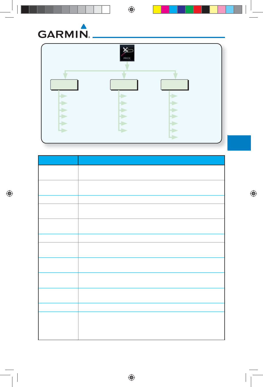
6-3190-01007-03 Rev. J
Garmin GTN 725/750 Pilot’s Guide
Foreword
Getting
Started
Audio &
Xpdr Ctrl
Com/Nav
FPL
Direct-To
Proc
Charts
Wpt Info
Map
Traffic
Terrain
Weather
Nearest
Services/
Music
Utilities
System
Messages
Symbols
Appendix
Index
Approach
Airport
Approach
Transition
Channel/ID
Preview
Load Approach
Activate Approach
Arrival
Airport
Arrival
Transition
Runway
Preview
Load Arrival
Departure
Airport
Departure
Runway
Transition
Preview
Load Departure
Figure 6-1 Procedures Functional Diagram
Annunciation Description
LPV Localizer Performance with Vertical guidance (LPV) approach. Fly to LPV
minimums.
LP +V Localizer Performance using published LP minima. Advisory vertical guidance is
provided. Fly to LP minimums.
LP Localizer Performance with no vertical guidance. Fly to LP minimums.
L/VNAV Lateral Navigation and Vertical Navigation (LNAV/VNAV) approach. Fly to
LNAV/VNAV minimums.
LNAV+V GPS approach using published LNAV minima. Advisory vertical guidance is
provided. Fly to LNAV minimums.
LNAV Lateral Navigation approach. Fly to LNAV minimums.
MAPR Missed Approach indicates the system is providing missed approach integrity
and CDI full-scale deflection ±0.3 NM.
ENR En route, CDI full-scale deflection is 2.0 NM or current CDI scale selection,
whichever is smaller.
TERM Terminal, CDI full-scale deflection is 1.0 NM or current CDI scale selection,
whichever is smaller.
DPRT Departure, indicates the system is using non-precision approach integrity.
CDI full-scale deflection is 0.3 NM.
OCN Oceanic, CDI full-scale deflection is 2.0 NM.
LOW ALT
(lower window)
For LNAV+V, LNAV/VNAV, or LPV approaches, the LOW ALT annunciation
indicates the aircraft’s estimated height is lower than the Final Approach
Waypoint height by approximately 50 meters. This annunciation will not be
active when TAWS is operational.
Table 6-1 Phase of Flight Annunciations
190-01007-03-Final.indb 3 7/9/2015 2:07:16 PM
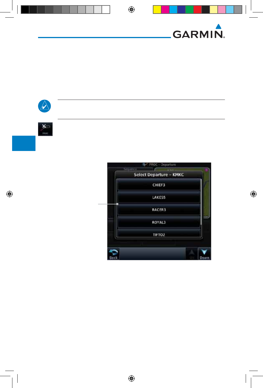
6-4
Garmin GTN 725/750 Pilot’s Guide
190-01007-03 Rev. J
Foreword
Getting
Started
Audio &
Xpdr Ctrl
Com/Nav
FPL
Direct-To
Proc
Charts
Wpt Info
Map
Traffic
Terrain
Weather
Nearest
Services/
Music
Utilities
System
Messages
Symbols
Appendix
Index
6.2 Selecting a Departure
A Departure Procedure (DP) is loaded at the departure airport in the flight
plan. Only one departure can be loaded at a time in a flight plan. If a departure
is loaded when another departure is already in the active flight plan, the new
departure replaces the previous departure. The route is defined by selection of a
departure, the transition waypoint, and a runway.
NOTE: Vector-only departures are not available in the Procedures database
as the GTN 7XX cannot provide navigational guidance on vectored legs.
1. Touch the PROC key on the Home page and then touch the
Departure key to display the Departure list.
2. If necessary, touch the Airport key and enter the departure
airport. Touch the key for the desired Departure.
Touch To Select
Desired Departure
Figure 6-2 List for Selecting a Departure
190-01007-03-Final.indb 4 7/9/2015 2:07:16 PM
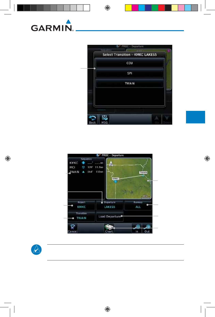
6-5190-01007-03 Rev. J
Garmin GTN 725/750 Pilot’s Guide
Foreword
Getting
Started
Audio &
Xpdr Ctrl
Com/Nav
FPL
Direct-To
Proc
Charts
Wpt Info
Map
Traffic
Terrain
Weather
Nearest
Services/
Music
Utilities
System
Messages
Symbols
Appendix
Index
3. Touch the key for the desired Transition.
Touch To Select
Desired Departure
Transition
Figure 6-3 Selecting a Transition for a Departure
4. Touch the key for the desired Runway, if necessary. The
Departure page with preview will be displayed.
Touch To Select
Runway
Touch To Select
Transition
Touch To Select
Departure
Touch To Select
Airport
Sequence List
For The Selected
Departure Departure
Diagram
Touch To Load
Departure
Touch To View
Charts
Figure 6-4 Departure Selected
NOTE: If the selected runway is depicted as RW10B, for instance, this
means both runways 10L and 10R.
190-01007-03-Final.indb 5 7/9/2015 2:07:16 PM
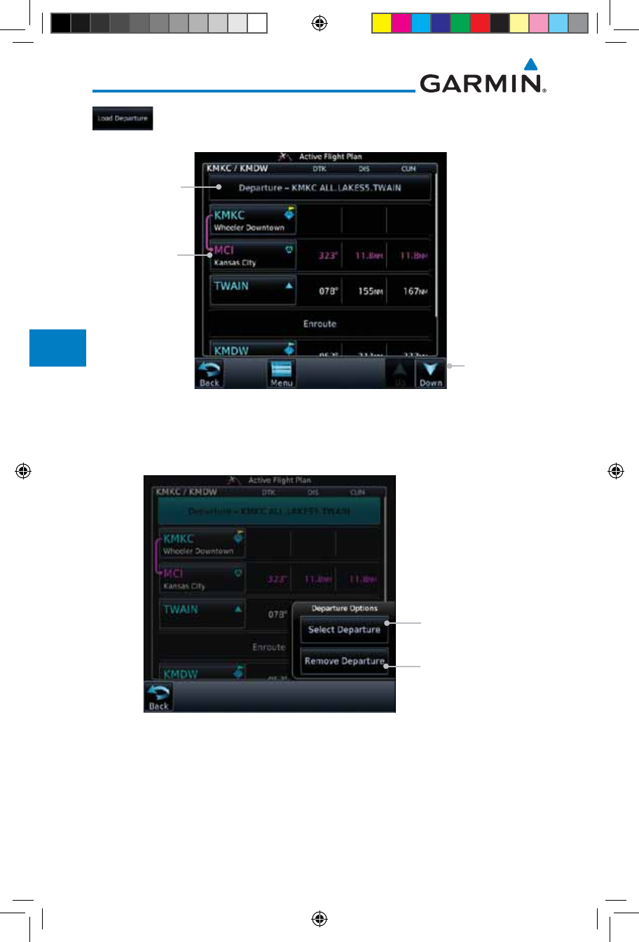
6-6
Garmin GTN 725/750 Pilot’s Guide
190-01007-03 Rev. J
Foreword
Getting
Started
Audio &
Xpdr Ctrl
Com/Nav
FPL
Direct-To
Proc
Charts
Wpt Info
Map
Traffic
Terrain
Weather
Nearest
Services/
Music
Utilities
System
Messages
Symbols
Appendix
Index
5. Touch the Load Departure key. The Active Flight Plan page
will be displayed.
Scroll To View
Flight Plan
With Departure
Waypoints
Touch To Edit
Waypoint
Touch To Change
Or Remove
Departure
Figure 6-5 Flight Plan After Loading a Departure
6. Remove a departure or select a new one by touching the
Departure key and selecting the desired choice.
Touch To Change
A Departure
Touch To Remove
Departure
Figure 6-6 Editing a Departure
190-01007-03-Final.indb 6 7/9/2015 2:07:16 PM
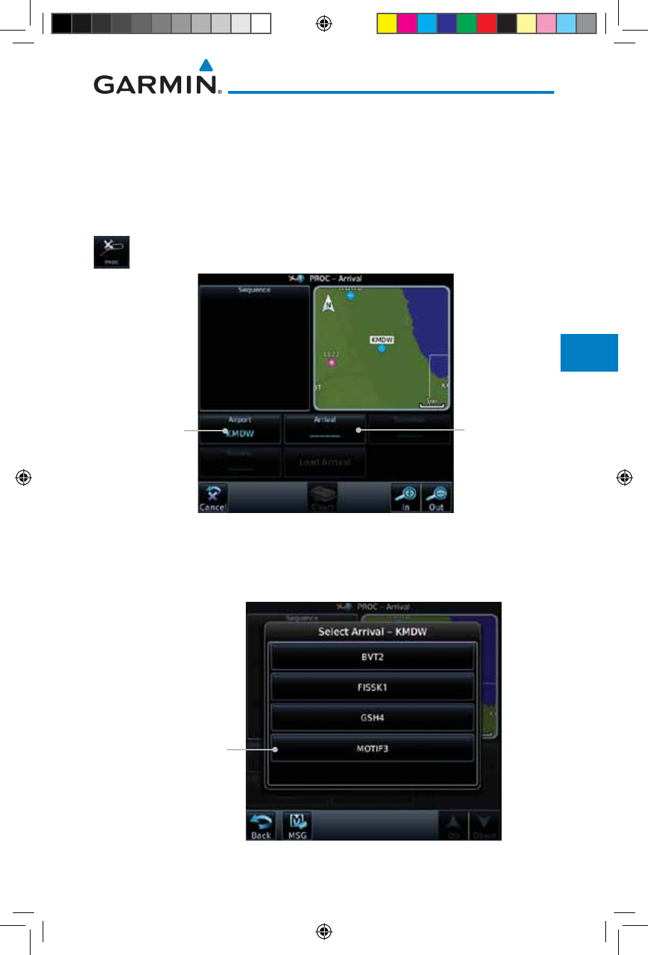
6-7190-01007-03 Rev. J
Garmin GTN 725/750 Pilot’s Guide
Foreword
Getting
Started
Audio &
Xpdr Ctrl
Com/Nav
FPL
Direct-To
Proc
Charts
Wpt Info
Map
Traffic
Terrain
Weather
Nearest
Services/
Music
Utilities
System
Messages
Symbols
Appendix
Index
6.3 Selecting an Arrival
A Standard Terminal Arrival (STAR) can be loaded at any airport with
a published arrival procedure. Only one arrival can be loaded at a time in a
flight plan. If an arrival is loaded when another arrival is already in the active
flight plan, the new arrival replaces the previous arrival. The route is defined by
selection of an arrival, the transition waypoint, and a runway.
1. Touch the PROC key on the Home page and then touch the
Arrival key.
Touch To Select
Airport Touch To Show
Arrival List
Figure 6-7 Arrival Page
2. Confirm that the intended airport is shown or touch the
Airport key and select the desired airport. Touch the key for
the desired Arrival.
Touch To Select
Arrival
Figure 6-8 Arrival List
190-01007-03-Final.indb 7 7/9/2015 2:07:16 PM
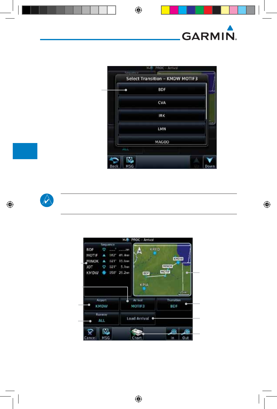
6-8
Garmin GTN 725/750 Pilot’s Guide
190-01007-03 Rev. J
Foreword
Getting
Started
Audio &
Xpdr Ctrl
Com/Nav
FPL
Direct-To
Proc
Charts
Wpt Info
Map
Traffic
Terrain
Weather
Nearest
Services/
Music
Utilities
System
Messages
Symbols
Appendix
Index
3. Touch the Transition key and then touch the key for the
desired transition.
Touch To Select
Desired Arrival
Transition
Figure 6-9 Select Transition
4. Touch the key for the desired Runway, if necessary.
NOTE: If the selected runway is depicted as RW10B, for instance, this
means both runways 10L and 10R.
5. After selecting the runway, the Arrival page with map preview
will be displayed.
Touch To Select
Transition
Touch To Select
Runway
Touch To Select
Arrival
Touch To Select
Airport
Sequence List
For The Selected
Arrival Arrival
Diagram
Touch To Load
Arrival
Touch To View
Charts
Figure 6-10 Previewing an Arrival
190-01007-03-Final.indb 8 7/9/2015 2:07:17 PM
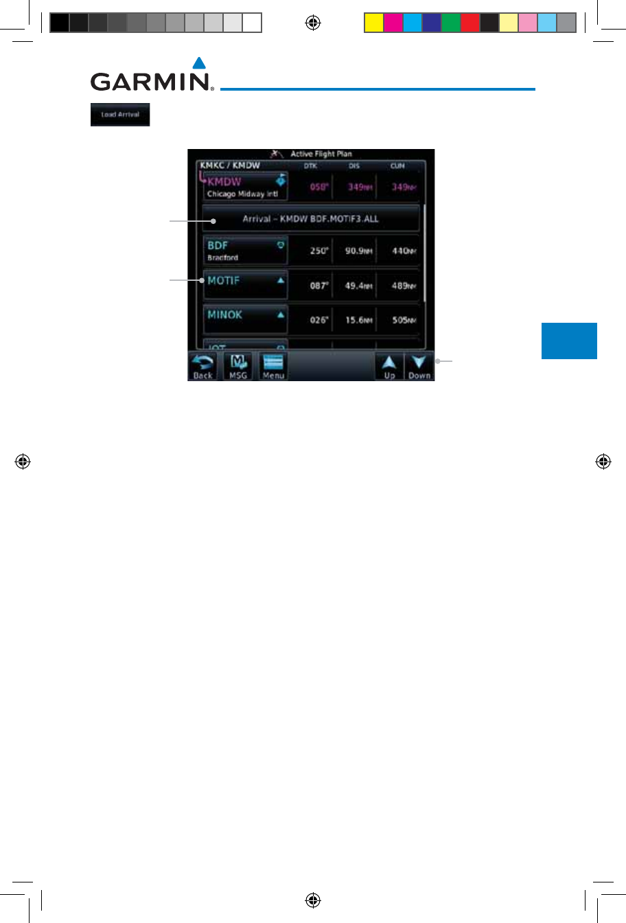
6-9190-01007-03 Rev. J
Garmin GTN 725/750 Pilot’s Guide
Foreword
Getting
Started
Audio &
Xpdr Ctrl
Com/Nav
FPL
Direct-To
Proc
Charts
Wpt Info
Map
Traffic
Terrain
Weather
Nearest
Services/
Music
Utilities
System
Messages
Symbols
Appendix
Index
6. Touch the Load Arrival key. The Active Flight Plan page will
be displayed.
Scroll To View
Flight Plan
With Departure
Waypoints
Touch To Edit
Waypoint
Touch To Select
Or Remove
Arrival
Figure 6-11 Flight Plan With Arrival Loaded
190-01007-03-Final.indb 9 7/9/2015 2:07:17 PM
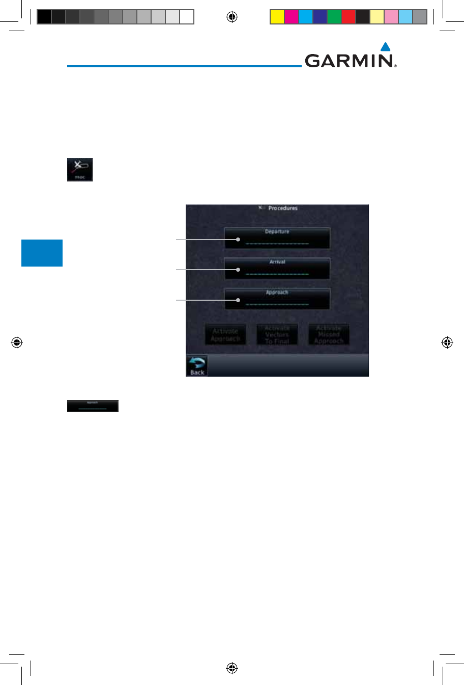
6-10
Garmin GTN 725/750 Pilot’s Guide
190-01007-03 Rev. J
Foreword
Getting
Started
Audio &
Xpdr Ctrl
Com/Nav
FPL
Direct-To
Proc
Charts
Wpt Info
Map
Traffic
Terrain
Weather
Nearest
Services/
Music
Utilities
System
Messages
Symbols
Appendix
Index
6.4 Selecting an Approach
Only one approach can be loaded at a time in a flight plan. If an approach
is loaded when another approach is already in the active flight plan, the new
approach replaces the previous approach. The route is defined by selection of an
approach, the transition waypoint, and a runway.
1. Touch the PROC key on the Home page. The Approach,
Arrival, and Departure fields will be dashed until a selection
is made.
Touch To View
Available Departures
Touch To View
Available Arrivals
Touch To View
Available Approaches
Figure 6-12 Procedures Selection Window
2. Touch the Approach key on the Procedures page to select
an approach for the destination airport. Confirm that the
intended airport is shown or touch the Airport key and select
the desired airport.
190-01007-03-Final.indb 10 7/9/2015 2:07:17 PM
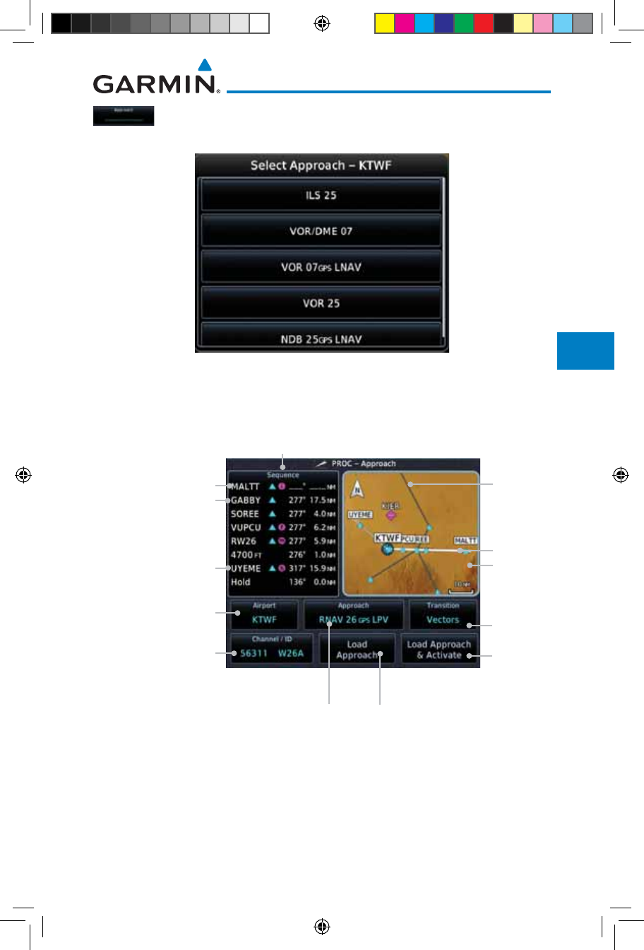
6-11190-01007-03 Rev. J
Garmin GTN 725/750 Pilot’s Guide
Foreword
Getting
Started
Audio &
Xpdr Ctrl
Com/Nav
FPL
Direct-To
Proc
Charts
Wpt Info
Map
Traffic
Terrain
Weather
Nearest
Services/
Music
Utilities
System
Messages
Symbols
Appendix
Index
3. Touch the Approach key on the Procedures-Approach page
and then touch the key for the desired approach.
Figure 6-13 Selecting an Approach
4. After selecting the approach for the destination airport, the
approach options will be displayed.
Final Approach Fix
Missed Approach Point
Missed Approach Hold
Point
Sequence List For The Selected Transition
Approach
Diagram
Current Dest
Waypoint. Touch To
Select Airport.
Touch To Select
Channel/ID
Touch To Select Approach Touch To Load Approach
Touch
To Select
Transition
Touch To
Activate
Approach
Unselected
Transition
Selected
Transition
Figure 6-14 Selected Approach Options
190-01007-03-Final.indb 11 7/9/2015 2:07:17 PM
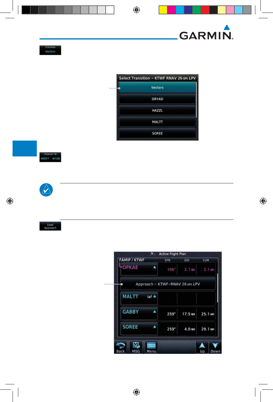
6-12
Garmin GTN 725/750 Pilot’s Guide
190-01007-03 Rev. J
Foreword
Getting
Started
Audio &
Xpdr Ctrl
Com/Nav
FPL
Direct-To
Proc
Charts
Wpt Info
Map
Traffic
Terrain
Weather
Nearest
Services/
Music
Utilities
System
Messages
Symbols
Appendix
Index
5. Touch the Transition key and then touch the key for the desired
transition. The selected Transition will be shown in white on
the Procedure page Approach diagram. Unselected Transitions
will be shown in grey.
Touch To Select
Transition
Figure 6-15 Select Approach Transition
6. If desired, touch the Channel/ID key, then use the numeric
keypad to select the channel number, and then touch the Enter
key. The Channel and ID are typically loaded automatically if
they are present.
NOTE: As an alternate means of loading an approach, the Channel ID key
allows you to select the channel ID for a SBAS approach for the current
destination. The channel ID for the SBAS approach is available from an
approved approach chart. If duplicate numbers are available for a channel,
a list will be available where you may select the desired approach.
7. Touch the Load Approach key. The Active Flight Plan page
will be displayed. The approach waypoints are placed at the
end of the flight plan and the unit will automatically sequence
to them after the en route waypoints.
Approach Waypoints
Figure 6-16 After Loading an Approach
190-01007-03-Final.indb 12 7/9/2015 2:07:18 PM
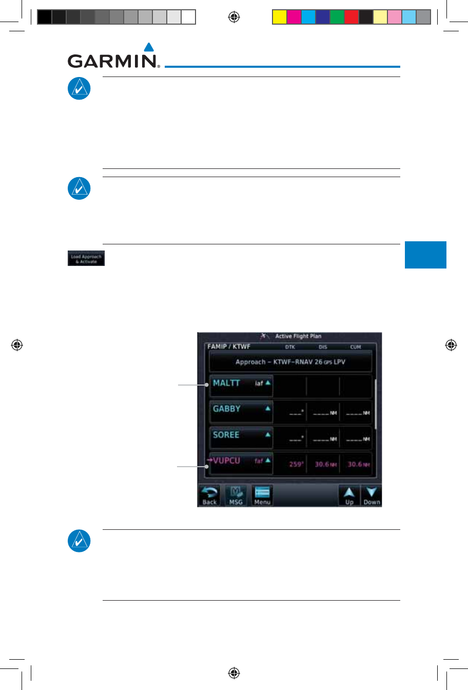
6-13190-01007-03 Rev. J
Garmin GTN 725/750 Pilot’s Guide
Foreword
Getting
Started
Audio &
Xpdr Ctrl
Com/Nav
FPL
Direct-To
Proc
Charts
Wpt Info
Map
Traffic
Terrain
Weather
Nearest
Services/
Music
Utilities
System
Messages
Symbols
Appendix
Index
NOTE: In software version 6.00 and later, if you build your flight plan with
the destination airport at the end and then load an approach procedure, the
destination airport will be removed from the end of the flight plan. If the
leg to the destination airport is the active leg when loading an approach
procedure, you will navigate all the way to the destination airport before
joining the procedure. Be sure when LOADING and not ACTIVATING an
approach procedure that the route to be flown is correct.
NOTE: In software version 5.13 and earlier, if you build your flight plan with
the destination airport at the end and then load an approach procedure,
you will navigate all the way to the destination airport before joining the
procedure. Be sure when LOADING and not ACTIVATING an approach
procedure that the route to be flown is correct.
8. Touch the Load Approach & Activate key, which makes
the active leg Direct-To the selected transition waypoint, or
for Vector approaches to activate a leg that is an extended
final approach course. You can also “activate” the selected
procedure on the Procedures page, if the approach is not
activated on this page.
Approach Waypoints
Direct-To Waypoint
Figure 6-17 After Activating the Approach
NOTE: When re-activating an approach, the decision as to whether a hold
is inserted at the IAF or not is assumed to be the same as the first time
the approach was activated, regardless of current aircraft position. If the
pilot wishes to have the hold inserted or removed from the procedure, the
procedure must be re-loaded or activated from the PROC-Approach page.
190-01007-03-Final.indb 13 7/9/2015 2:07:18 PM
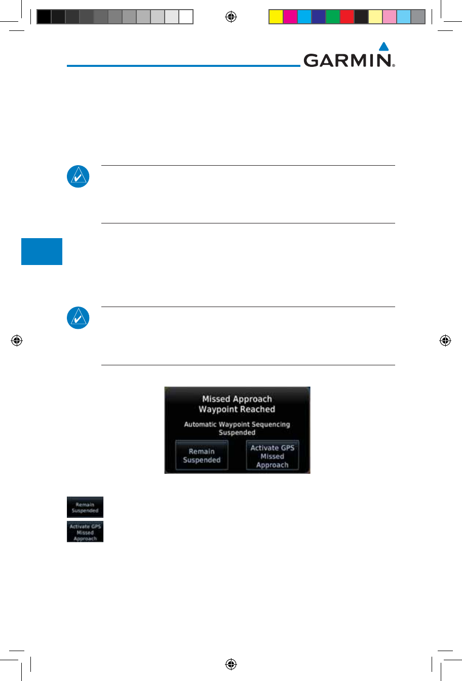
6-14
Garmin GTN 725/750 Pilot’s Guide
190-01007-03 Rev. J
Foreword
Getting
Started
Audio &
Xpdr Ctrl
Com/Nav
FPL
Direct-To
Proc
Charts
Wpt Info
Map
Traffic
Terrain
Weather
Nearest
Services/
Music
Utilities
System
Messages
Symbols
Appendix
Index
6.5 Approaches with Procedure Turns
The procedure turn portion of an approach is stored as one of the legs of
the approach. For this reason, the GTN 7XX unit requires no special operations
from the pilot — other than flying the procedure turn itself — beyond what is
required for any other type of approach. Roll steering is provided to aircraft with
compatible autopilots.
NOTE: The steering provided for the procedure turn does not guarantee
that the aircraft will stay within charted procedure turn boundaries. As
such the crew will need to ensure that the approach is flown within the
confines of the charted procedure.
6.6 Flying the Missed Approach
Upon reaching the Missed Approach Point, the GTN 7XX unit continues to
give guidance along an extension of the final course segment (FAF to MAP) until
you manually initiate the missed approach procedure (as mentioned previously
in reference to the “SUSP” advisory).
NOTE: If the unit is not configured for a CDI key, then the “activate GPS missed
approach” will only resume automatic waypoint sequencing. The user must
switch to GPS navigation, if desired, by using their external source selection
method (this is typical an EFIS system).
1. When the MAP is reached, a pop-up will appear.
Figure 6-18 Pop-Up Upon Reaching the MAP
2. Touch the Remain Suspended key to continue with
sequencing suspended or touch Activate GPS Missed
Approach for guidance to the Missed Approach Hold Point.
The Activate GPS Missed Approach function is the same for the on screen
controls or a remote switch. Activating the missed approach prior to the MAP
can be accomplished on either the Flight Plan or Procedures pages. If using the
Flight Plan page, the approach banner must be touched to display the Approach
Options where Activate Missed Approach can be selected.
190-01007-03-Final.indb 14 7/9/2015 2:07:18 PM
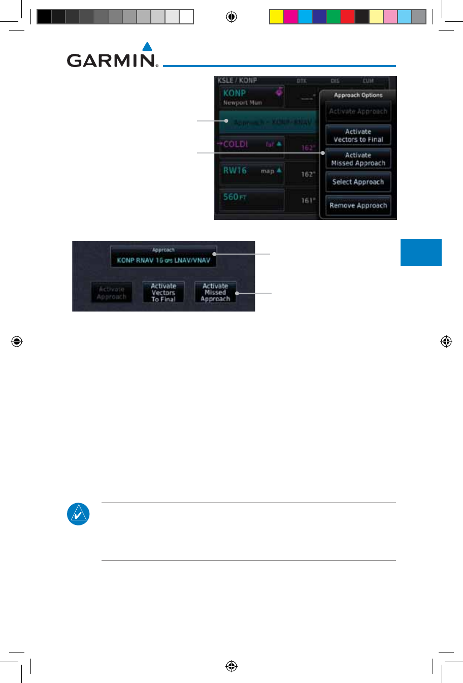
6-15190-01007-03 Rev. J
Garmin GTN 725/750 Pilot’s Guide
Foreword
Getting
Started
Audio &
Xpdr Ctrl
Com/Nav
FPL
Direct-To
Proc
Charts
Wpt Info
Map
Traffic
Terrain
Weather
Nearest
Services/
Music
Utilities
System
Messages
Symbols
Appendix
Index
Touch the Approach Banner to
Display the Approach Options
Touch the Desired Option
Figure 6-19 Approach Option Selection on the Flight Plan Page
Touch the Approach Banner to
Display the Approach Options
Touch the Desired Option
Figure 6-20 Approach Option Selection on the Procedures Page
Once an option is selected, the GTN will continue to provide guidance along
the final approach course. Upon reaching the MAP, the unit will automatically
sequence to the first leg of the missed approach. This is used when a pilot needs
to execute the missed approach prior to reaching the MAP.
6.7 Flying an Approach with a Hold
Upon activating an RNAV GPS approach, you are given the option to skip
any non-required holding patterns during the initial transitions of the approach.
The Flight Plan Page displays a timer or distance, as appropriate, during
the holding pattern. Use this timer or distance to fly the outbound portion of
the holding pattern. (The holding pattern is displayed on the Map Page and
indicated as the active leg on the Active Flight Plan pages.)
NOTE: If you need to lose extra altitude or speed by going around the holding
pattern again, touch SUSP to manually suspend waypoint sequencing BEFORE
crossing the holding waypoint the second time. If you’ve already passed this
waypoint, re-activate the holding pattern.
As you cross the MAP, a “SUSP” annunciation will appear, indicating that
automatic sequencing of approach waypoints is suspended at the MAP. A “from”
indication is displayed on the CDI and Default NAV Page, but course guidance
along the final approach course continues.
190-01007-03-Final.indb 15 7/9/2015 2:07:18 PM
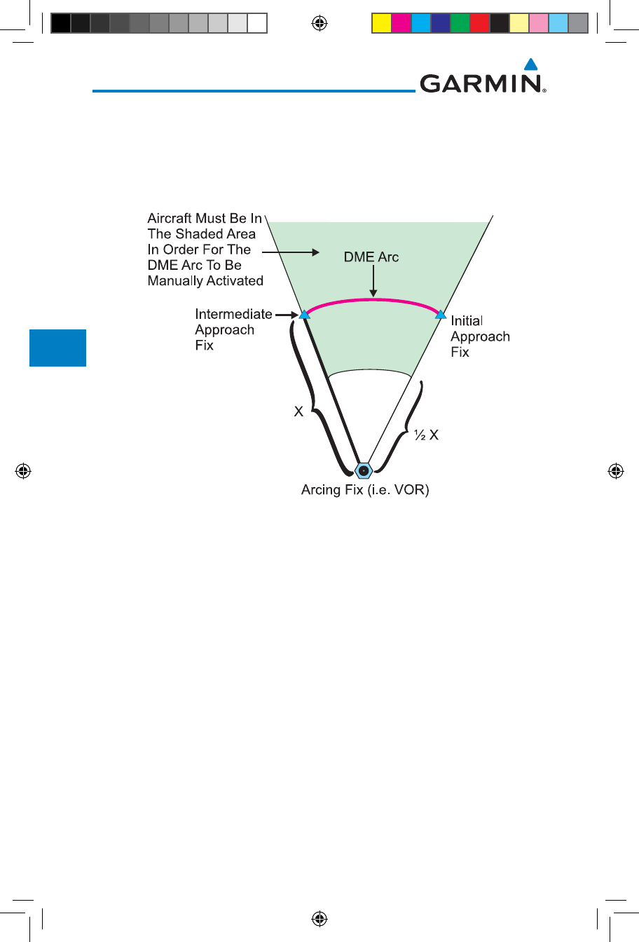
6-16
Garmin GTN 725/750 Pilot’s Guide
190-01007-03 Rev. J
Foreword
Getting
Started
Audio &
Xpdr Ctrl
Com/Nav
FPL
Direct-To
Proc
Charts
Wpt Info
Map
Traffic
Terrain
Weather
Nearest
Services/
Music
Utilities
System
Messages
Symbols
Appendix
Index
6.8 Flying a DME Arc Approach
Approaches that contain DME arcs are supported by the GTN. The GTN will
provide guidance (left / right) relative to the arc. If you wish to activate the DME
arc leg manually, the aircraft must be near the arc, as shown in the shaded area
below.
Figure 6-21 DME Arc Example
6.9 Radial-to-Fix (RF) Approaches
RF legs associated with RNAV RNP 1.0 non-AR (Approval Required)
approaches are supported by the GTN in version 6.00, or later, when approved
by the installation.
• AC 90-101A defines RF leg as "a constant radius circular path, around a
defined turn center, that starts and terminates at a fix. An RF leg may be
published as part of a procedure."
• Flying the RF leg of an approach is similar to flying a DME arc approach.
All GTN annunciations and indications are identical whether flying DME
arcs or RF legs with the GTN.
• RF legs may have a larger or smaller radius than DME arcs.
• Unlike DME arcs, RF legs are not based on a VOR.
• Refer to the aircraft AFMS for specific details regarding RF legs for a
specific aircraft.
190-01007-03-Final.indb 16 7/9/2015 2:07:19 PM
6-17190-01007-03 Rev. J
Garmin GTN 725/750 Pilot’s Guide
Foreword
Getting
Started
Audio &
Xpdr Ctrl
Com/Nav
FPL
Direct-To
Proc
Charts
Wpt Info
Map
Traffic
Terrain
Weather
Nearest
Services/
Music
Utilities
System
Messages
Symbols
Appendix
Index
6.10 Vectors to Final
With “Vectors-To-Final” (VTF) selected, the CDI needle remains off center
until you’re established on the final approach course. With the approach
activated, the Map Page displays an extension of the final approach course in
magenta (remember, magenta is used to depict the active leg of the flight plan)
and “vtf” appears as part of the active leg on the Map page (as a reminder that
the approach was activated with vectors-to-final).
NOTE: In software version 5.13 and earlier, once VTF is activated all waypoints
in the approach prior to the FAF are removed.
NOTE: In software version 6.00 and later, all waypoints along the final
approach course, including waypoints before the FAF, are included in the flight
plan and the final approach course to the FAF is activated.
190-01007-03-Final.indb 17 7/9/2015 2:07:19 PM
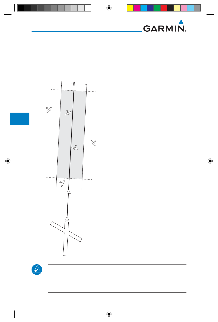
6-18
Garmin GTN 725/750 Pilot’s Guide
190-01007-03 Rev. J
Foreword
Getting
Started
Audio &
Xpdr Ctrl
Com/Nav
FPL
Direct-To
Proc
Charts
Wpt Info
Map
Traffic
Terrain
Weather
Nearest
Services/
Music
Utilities
System
Messages
Symbols
Appendix
Index
6.11 ILS Approaches (GTN 750 Only)
Precision ILS approaches can be performed with the built-in VLOC (VOR/
localizer/glideslope) receivers. The GPS receiver can be used for guidance prior
to reaching the final approach fix, but once there, the proper frequency must
be selected on the VLOC window (right side of screen) and the CDI output set
to “VLOC”.
2
NM
15
NM
1.2
NM
1.2
NM
MANUAL
FAF
VLOC
VLOC
GPS
GPS
Auto Switch to VLOC
within this area
The GTN 7XX can be set to automatically
switch the external CDI output from GPS to
VLOC as you intercept the final approach
course (if used with a KAP140/KFC225
autopilot, you will need to manually enable
outputs. See instructions in the “Enabling
Autopilot Outputs for the King KAP140/
KFC225” section). When the ILS approach
is activated and the correct ILS frequency is
active in the VLOC window, the GTN 7XX
automatically switches to VLOC within 1.2
NM left or right of the final approach course.
This switch can take place anywhere from
2.0 to 15.0 NM from the FAF.
The illustration shows multiple locations
along the approach path and the CDI
selection that you can expect: GPS or VLOC.
Within the area of the shaded box, the
automatic switch from GPS to VLOC should
occur.
NOTE: If you attempt to intercept the approach course at a distance less
than 2.0 NM from the FAF, the GTN 7XX does not automatically switch
the CDI to VLOC. In this case, touch the CDI key to manually switch from
GPS to VLOC.
190-01007-03-Final.indb 18 7/9/2015 2:07:19 PM
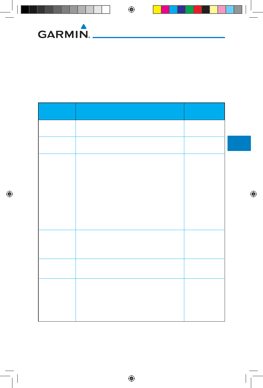
6-19190-01007-03 Rev. J
Garmin GTN 725/750 Pilot’s Guide
Foreword
Getting
Started
Audio &
Xpdr Ctrl
Com/Nav
FPL
Direct-To
Proc
Charts
Wpt Info
Map
Traffic
Terrain
Weather
Nearest
Services/
Music
Utilities
System
Messages
Symbols
Appendix
Index
The automatic switch from GPS to VLOC is not immediate, but instead occurs
gradually to prevent abrupt CDI changes when coupled to an autopilot. The CDI
selection can also be changed manually by touching the CDI key.
6.12 RNAV Approach Procedures
The GTN 7XX allows for flying LNAV/VNAV, LNAV, LNAV +V, LPV, LP, and
LP +V approaches according to the published chart.
Phase of flight
Annunciation
Description Minimums
L/VNAV Lateral Navigation/Vertical Navigation. RNAV non-
precision approach with vertical guidance.
Published LNAV/
VNAV minimums.
LNAV Lateral Navigation. RNAV non-precision approach. Published LNAV
minimums.
LNAV + V Lateral Navigation with Advisory Vertical
Guidance. RNAV non-precision LNAV approach
with advisory vertical guidance. The glidepath
is typically denoted by a light dashed line on
the vertical profile (Jeppeson only) with an
associated glidepath angle (usually in the 3.00
degree range) and is provided to assist the pilot
in maintaining a constant vertical glidepath,
similar to an ILS glideslope.
Published LNAV
minimums.
LPV Localizer Performance with Vertical guidance
(LPV) approach.
RNAV precision approach.
Published LPV
minimums.
LP LP indicates Localizer Performance with no
vertical guidance.
Published LP
minimums.
LP +V LP +V indicates Localizer Performance with
advisory vertical guidance. This annunciation
is available in software version 6.00 and later.
This advisory guidance follows the same nature
as set by the LNAV +V as shown above.
Published LP
minimums.
Table 6-2 RNAV Approach Annunciations
190-01007-03-Final.indb 19 7/9/2015 2:07:19 PM

6-20
Garmin GTN 725/750 Pilot’s Guide
190-01007-03 Rev. J
Foreword
Getting
Started
Audio &
Xpdr Ctrl
Com/Nav
FPL
Direct-To
Proc
Charts
Wpt Info
Map
Traffic
Terrain
Weather
Nearest
Services/
Music
Utilities
System
Messages
Symbols
Appendix
Index
6.12.1 Flying the LPV Approach
1. Within 31 NM of the destination, the GTN switches from en
route mode to terminal mode and the CDI scale transitions
from 2.0 to 1.0 NM, full scale deflection.
2. As you approach the IAF, a waypoint message appears on the
bottom of the screen.
3. As the distance (DIST) to the IAF approaches zero, the message
is replaced by a turn advisory that counts down 10 seconds
prior to the turn.
4. As you approach the FAF, the GTN will begin to automatically
rescale in an angular fashion. This will allow the LPV approach
to be flown in an identical fashion to a standard ILS. At
2.0 NM from the FAF, CDI scaling is tightened from 1.0 NM to
the angular full scale deflection (typically the angular full-scale
deflection is 2.0°, but will be as defined for the approach).
5. Sixty seconds prior to reaching the FAF, the unit will check the
required Horizontal Alarm Limit (HAL) and Vertical Alarm Limit
(VAL) to ensure the GPS position integrity is within limits to
complete the LPV precision approach. In the event the HAL
or VAL limits are exceeded, the approach will be downgraded
to a non-precision approach indicated by “LNAV” on the
moving map, a message that the approach is downgraded
(“APPROACH DOWNGRADE - GPS approach downgraded. Use
LNAV minima.”), and the glideslope indicator will be flagged.
You may continue the approach using LNAV non-precision
minimums if there are LNAV minimums for this approach. In
the rare event the GPS integrity cannot meet the non-precision
HAL limits, the unit will send a message to the pilot to abort
the approach (“ABORT APPROACH - GPS approach no longer
available.”). The unit will revert to terminal limits to support
navigation to the missed approach when the message is
acknowledged. After the aircraft has passed the FAF, a loss of
WAAS integrity will cause the approach to abort instead of
downgrade.
6. Capture the glideslope as you would an ILS glideslope.
190-01007-03-Final.indb 20 7/9/2015 2:07:19 PM

6-21190-01007-03 Rev. J
Garmin GTN 725/750 Pilot’s Guide
Foreword
Getting
Started
Audio &
Xpdr Ctrl
Com/Nav
FPL
Direct-To
Proc
Charts
Wpt Info
Map
Traffic
Terrain
Weather
Nearest
Services/
Music
Utilities
System
Messages
Symbols
Appendix
Index
7. As you cross the FAF, the destination sequences to the MAP
(e.g. “RW31”, the runway threshold). With the needle on the
external CDI (or HSI) centered, fly toward the MAP, observing
the altitude minimums published on the approach plate.
8. When viewing the Map Page, you’ll note that the final course
segment is displayed in magenta (the active leg of the flight
plan always appears in magenta).
9. As you approach the MAP, a waypoint message appears on
the bottom of the screen.
10. Once the unit crosses the MAP (defined as the runway end
waypoint), sequencing will be suspended. Prepare the aircraft
for missed approach operation. Touch the Unsuspend key to
sequence to the Missed Approach procedure.
11. Fly the guidance provided by the unit to the MAHP and hold.
6.12.2 Flying the LP Approach
An LP approach is flown similarly to an LNAV approach, except the precision
is greater as it utilizes the SBAS accuracy. It has similar lateral accuracy as an LPV
approach. Angular scaling is similar to a localizer approach. Most LP approaches
have step down altitudes associated with them. The approach still results in an
MDA and missed approach point.
If the approach is indicated as LP +V, advisory vertical guidance will be
provided. This does not change how the approach should be flown, and the
pilot is still responsible for descending to the correct altitude at each step down.
The approach still results in an MDA and missed approach point.
1. Within 30 NM of the destination, the GTN switches from en
route mode to terminal mode and the CDI scale transitions
from 2.0 to 1.0 NM, full scale deflection.
2. As you approach the IAF, a turn direction message appears on
the bottom of the screen.
3. As the distance (DIST) to the IAF approaches zero, the message
is replaced by a time to turn advisory that counts down 10
seconds prior to the turn.
4. As you approach the FAF, the GTN will begin to automatically
rescale in an angular fashion. This will allow the LP approach to
be flown in the same fashion as a standard localizer approach.
At 2.0 NM from the FAF, CDI scaling is tightened from up to
either 2° or 0.3 NM, full scale deflection, whichever is smaller.
190-01007-03-Final.indb 21 7/9/2015 2:07:19 PM
6-22
Garmin GTN 725/750 Pilot’s Guide
190-01007-03 Rev. J
Foreword
Getting
Started
Audio &
Xpdr Ctrl
Com/Nav
FPL
Direct-To
Proc
Charts
Wpt Info
Map
Traffic
Terrain
Weather
Nearest
Services/
Music
Utilities
System
Messages
Symbols
Appendix
Index
5. Sixty seconds prior to reaching the FAF, the GTN will check
the required Horizontal Alarm Limit (HAL) to ensure the GPS
position integrity is within limits to complete the LP non-
precision approach. In the event the HAL limits are exceeded,
the approach will be downgraded, when available, indicated
by “LNAV” on the moving map, otherwise the approach
will be aborted. A message will note that the approach is
downgraded and the NAV indicator will be flagged until the
message is viewed. You may continue the approach using
LNAV non-precision minimums if there are LNAV minimums
for this approach. In the rare event the GPS HAL limits cannot
meet non-precision limits, the GTN will notify the pilot with
a message to abort the approach. The GTN will revert to
terminal limits of 1.0 NM to support navigation to the missed
approach. If the approach is indicating an LP +V, it is possible
that the advisory vertical guidance could be removed without
annunciation due to the vertical guidance not being within
tolerances. This does not constitute a downgrade, and the
approach can still be flown to LP minimums.
6. As you cross the FAF, the destination sequences to the MAP.
With the needle on the external CDI (or HSI) centered, fly
toward the MAP, observing the altitude minimums published
on the approach plate.
7. When viewing the Map Page, you’ll note that the final course
segment is displayed in magenta (the active leg of the flight
plan always appears in magenta).
8. As you approach the MAP, a waypoint message (“Arriving at
Waypoint”) appears on the bottom of the screen.
9.
At the MAP initiate the missed approach, if necessary. Once
the GTN crosses the MAP, sequencing will be suspended.
Prepare the aircraft for missed approach operation. Touch the
Unsuspend key to sequence to the Missed Approach procedure.
NOTE: For missed approaches with heading legs, fly manually until the
first active course leg is reached.
10. Fly the guidance provided by the GTN to the MAHP and hold.
190-01007-03-Final.indb 22 7/9/2015 2:07:19 PM
6-23190-01007-03 Rev. J
Garmin GTN 725/750 Pilot’s Guide
Foreword
Getting
Started
Audio &
Xpdr Ctrl
Com/Nav
FPL
Direct-To
Proc
Charts
Wpt Info
Map
Traffic
Terrain
Weather
Nearest
Services/
Music
Utilities
System
Messages
Symbols
Appendix
Index
6.13 Points to Remember for All Procedures
• The GTN 7XX Map page is designed to complement your approach
plates and vastly improve situational awareness throughout the approach.
However, you must always fly an approach as it appears on the approach plate.
• The active leg (or the portion of the approach currently in use) is depicted
in magenta on the Map Page. As you fly the approach, the GTN 7XX
automatically sequences through each leg of the approach unless “SUSP”
appears at the annunciation bar at the bottom of the display. “SUSP”
indicates that automatic sequencing of approach waypoints is suspended
on the current leg and normally appears at holding patterns, upon crossing
the missed approach point (MAP), for Climb to Altitude legs, and for Hold
to Altitude legs.
• For roll steering autopilots: roll steering is terminated when approach mode
is selected on the autopilot and is available once the missed approach is
initiated.
• If Vectors-to-Final is activated while on the “FROM” side of the FAF,
automatic waypoint sequencing is suspended and the SUSP annunciation
will appear. Automatic waypoint sequencing will resume once the aircraft is
on the “TO” side of the FAF and within full-scale deflection.
• For all procedures, make sure to check the runway, transition, and all
waypoints.
CAUTION: Not all autopilots will follow guidance when on a heading leg
using NAV, GPSS, or APR mode on the autopilot. Heading legs for procedures
can be identified by “HDG XXX°” in white on the Flight Plan page, as well
as the procedure chart indicating that the aircraft must fly a particular
heading. Certain autopilots will revert to a “Roll Only” or “Wings Level”
mode on these leg types and the pilot must engage the heading (HDG)
mode of the autopilot and set the heading bug appropriately in order to
use the autopilot on these legs.
190-01007-03-Final.indb 23 7/9/2015 2:07:19 PM
6-24
Garmin GTN 725/750 Pilot’s Guide
190-01007-03 Rev. J
Foreword
Getting
Started
Audio &
Xpdr Ctrl
Com/Nav
FPL
Direct-To
Proc
Charts
Wpt Info
Map
Traffic
Terrain
Weather
Nearest
Services/
Music
Utilities
System
Messages
Symbols
Appendix
Index
6.14 Points to Remember for Localizer or
VOR-based Approaches
• The default factory setting allows the CDI output to automatically switch
from the GPS receiver to the LOC receiver. This may be changed to manual
in some installations. If the “ILS CDI Selection” setting is changed to
“Manual”, you must determine when to select “GPS” or “VLOC” guidance
during the approach. Remember, “VLOC” is required for the final course
segment from the Final Approach Fix (FAF) to the MAP.
NOTE: Installations with certain autopilots, such as the KAP 140 and
KFC225, do not allow automatic ILS CDI switching.
NOTE: GPS phase of flight annunciations (LPV, ENR, etc.) are not applicable
to the external CDI (or HSI) when VLOC is active.
• If the CDI output has not automatically switched from GPS to ILS upon
reaching the FAF, you must manually switch to the VLOC receiver by
touching the CDI key. Verify that “VLOC” is displayed.
• Automatic switching of CDI output is available for ILS, localizer, SDF and
LDA approaches. Automatic CDI switching is not available for backcourse
approaches or VOR approaches.
• When flying an approach with the autopilot-coupled, you must monitor
system functions at all times and verify that the autopilot and external CDI
(or HSI) switch to the VLOC receiver with sufficient time to capture and
track the approach course. Switching to “VLOC” late in the approach may
not provide the autopilot enough time to respond and intercept the approach
course prior to the FAF (depending upon the performance characteristics of
your autopilot and aircraft).
• When an ILS or VOR approach is first selected or executed, the frequency
is automatically checked. If the frequency is incorrect, you will receive a
message and you must place the correct ILS or VLOC frequency in the
active frequency field.
• When flying a localizer-based approach (other than backcourse) with
automatic CDI switching enabled:
190-01007-03-Final.indb 24 7/9/2015 2:07:20 PM
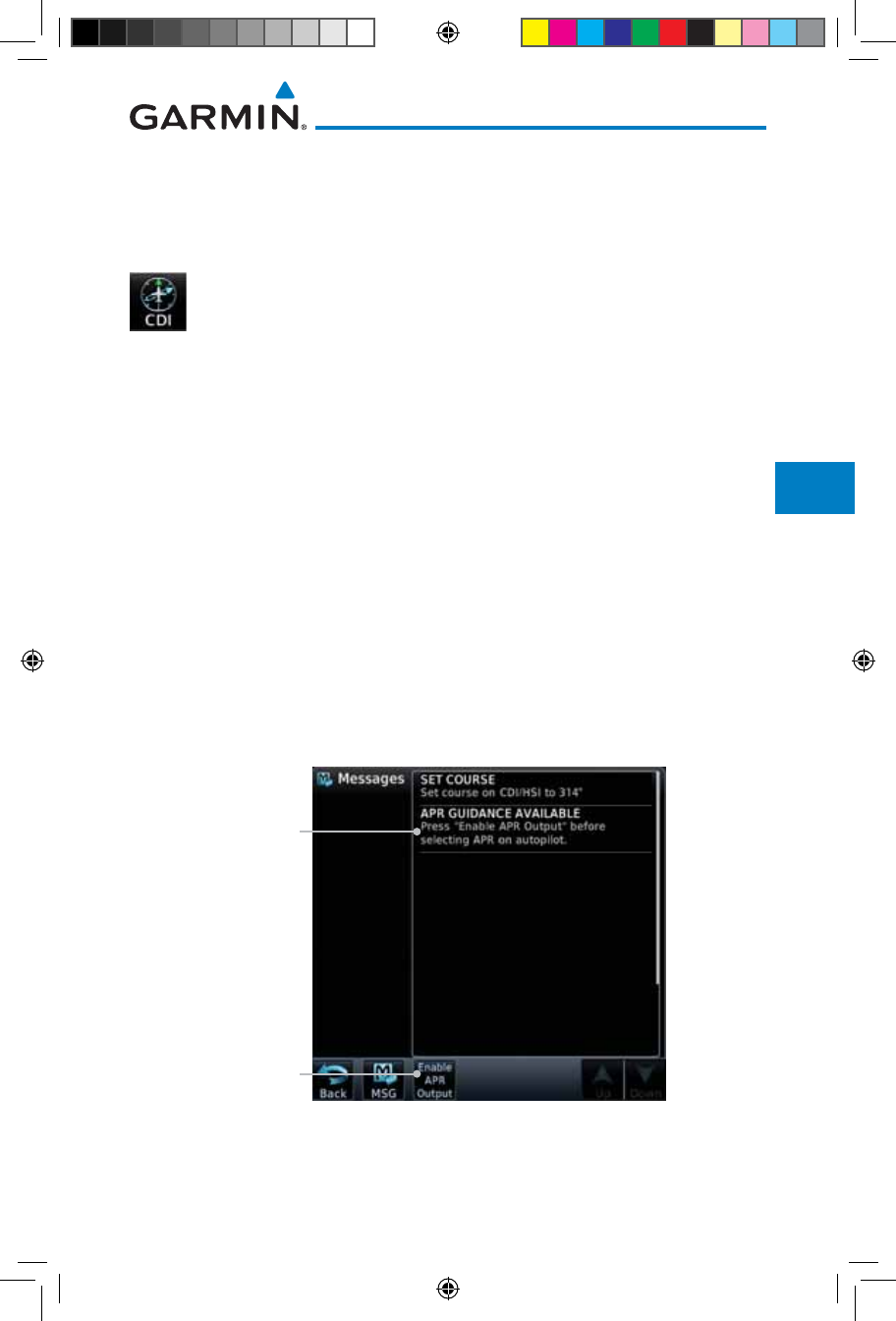
6-25190-01007-03 Rev. J
Garmin GTN 725/750 Pilot’s Guide
Foreword
Getting
Started
Audio &
Xpdr Ctrl
Com/Nav
FPL
Direct-To
Proc
Charts
Wpt Info
Map
Traffic
Terrain
Weather
Nearest
Services/
Music
Utilities
System
Messages
Symbols
Appendix
Index
1. “GPS” guidance may be used while flying outbound and on
the initial portion of the procedure turn.
2. “VLOC” guidance is used on the remainder of the approach
from the time you turn inbound on the procedure turn.
3. The localizer frequency must be active to use “VLOC” guidance
at the MAP.
• When flying a localizer-based approach with automatic CDI switching
disabled.
1. You may select “VLOC” guidance at any point on the approach
prior to reaching the FAF.
2. The localizer frequency must be active to use “VLOC”
guidance.
6.15 Enabling Autopilot Outputs for the
King KAP140/KFC225
Autopilot outputs for the King KAP140/KFC225 autopilots are activated
manually by the pilot after being prompted during the approach procedure. After
enabling outputs, the GTN 7XX will provide guidance information consistent
with what the autopilot expects (i.e., angular CDI scaling and glideslope capture
for an LPV or other vertically guided GPS approach).
Prompt To Activate
Autopilot Outputs
Touch To Activate
Autopilot Outputs
Figure 6-22 Prompt To Activate Autopilot Outputs
190-01007-03-Final.indb 25 7/9/2015 2:07:20 PM

6-26
Garmin GTN 725/750 Pilot’s Guide
190-01007-03 Rev. J
Foreword
Getting
Started
Audio &
Xpdr Ctrl
Com/Nav
FPL
Direct-To
Proc
Charts
Wpt Info
Map
Traffic
Terrain
Weather
Nearest
Services/
Music
Utilities
System
Messages
Symbols
Appendix
Index
This page intentionally left blank
190-01007-03-Final.indb 26 7/9/2015 2:07:20 PM
7-1190-01007-03 Rev. J
Garmin GTN 725/750 Pilot’s Guide
Foreword
Getting
Started
Audio &
Xpdr Ctrl
Com/Nav
FPL
Direct-To
Proc
Charts
Wpt Info
Map
Traffic
Terrain
Weather
Nearest
Services/
Music
Utilities
System
Messages
Symbols
Appendix
Index
7 CHARTS
NOTE: The availability of SafeTaxi, ChartView, or FliteCharts in electronic
form may not preclude the requirement to carry paper charts aboard the
aircraft. See the AFMS for more information.
NOTE: The Chart feature provides a digital representation of a paper
chart and provides no vertical or lateral course guidance. Flight Plan and
Procedures are separate from Charts, and do provide vertical and lateral
course guidance for the loaded route or procedure shown on the Flight
Plan page. The term “Chart Unavailable” means that the chart cannot be
viewed on the Charts due to either a chart not being published, or an error
in the Chart database, but does not preclude its availability or inclusion of
the procedure in the Flight Plan or Procedures portion of the system. The
absence of a chart for a particular Departure, Arrival, or Approach does
not preclude its availability or inclusion in the Flight Plan or Procedures
portion of the system. The absence of a particular Departure, Arrival, or
Approach under the Flight Plan or Procedures portion of the system does
not preclude the ability to view the Chart for that procedure under the
Chart feature.
NOTE: Features that are selectable on the main map page, such as obstacles,
airports, airspace, and other waypoint types that are not visible beneath the
overlaid chart, remain selectable even when an approach chart is overlaid
on the main map.
NOTE: Do not use SafeTaxi or Chartview functions as the basis for ground
maneuvering. SafeTaxi and Chartview functions do not comply with the
requirements of AC 20-159 and are not qualified to be used as an airport
moving map display (AMMD). SafeTaxi and Chartview are to be used by
the flight crew to orient themselves on the airport surface to improve pilot
situational awareness during ground operations.
The chart page will default to the nearest airport if no flight plan or destination
airport is present. While you are on the ground, the displayed charts will default
to the current airport location regardless of flight plan. The optional ChartView
and FliteCharts provide on-board electronic terminal procedures charts.
Electronic charts offer the convenience of rapid access to essential information.
Either ChartView or FliteCharts may be configured in the system, but not both.
ChartView resembles the paper version of Jeppesen terminal procedures
charts. The charts are displayed in full color with high-resolution. The Map
depiction shows the aircraft position on the moving map in the plan view of
190-01007-03-Final.indb 1 7/9/2015 2:07:20 PM
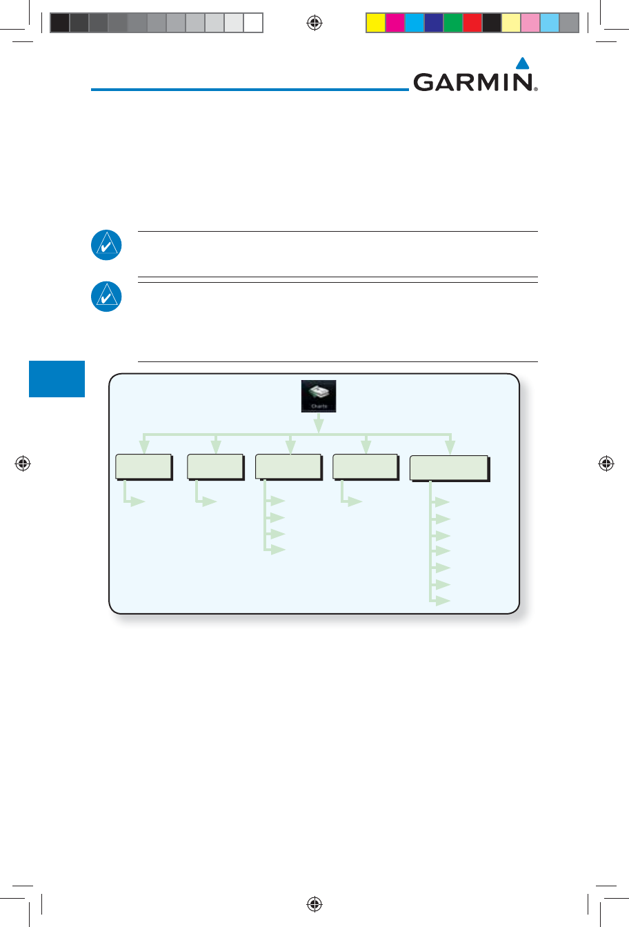
7-2
Garmin GTN 725/750 Pilot’s Guide
190-01007-03 Rev. J
Foreword
Getting
Started
Audio &
Xpdr Ctrl
Com/Nav
FPL
Direct-To
Proc
Charts
Wpt Info
Map
Traffic
Terrain
Weather
Nearest
Services/
Music
Utilities
System
Messages
Symbols
Appendix
Index
approach charts and on airport diagrams. Airport Hot Spots are outlined in
magenta. The ChartView database subscription is available from Jeppesen, Inc.
Available data includes:
• Arrivals (STAR) • Airport Diagrams
• Departure Procedures (DP) • NOTAMs • Approaches
An enablement card that is purchased from Garmin is separate from the
Jeppesen database and is required to enable ChartView.
NOTE: The chart for the destination airport or loaded approach will
automatically be selected.
NOTE: If two GTN 7XX units are crossfilled, then the same type (ChartView
or FlightCharts) and version (cycle number and effective dates) for the chart
database must be installed on both units in order for the correct chart to
be overlaid on the main map page.
Menu
Full Screen
Invert Colors
All
Header
Plan
Profile
Mins
Select
Airport
Airport
View
Airport
Wpt
Info
Airport Info
View
Select
Detailed
Info
Info
Info
APR
DP
Arrival
Chart Detail
Figure 7-1 Charts Functional Diagram
The following list describes the order in priority in which charts are auto-loaded
in the system when the Chart page is displayed:
1. The most-recently selected chart during the current power cycle, if valid*,
2. The airport surface chart for the nearest airport, if on ground and nearest
airport is found,
3. The approach chart for the approach in the active flight plan, if approach
exists in the flight plan,
4. The airport surface chart for the last airport in the flight plan, if one exists,
190-01007-03-Final.indb 2 7/9/2015 2:07:20 PM
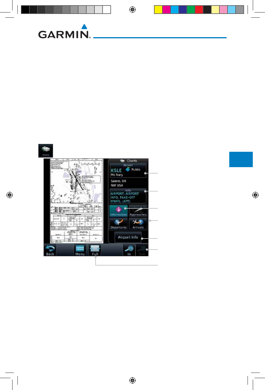
7-3190-01007-03 Rev. J
Garmin GTN 725/750 Pilot’s Guide
Foreword
Getting
Started
Audio &
Xpdr Ctrl
Com/Nav
FPL
Direct-To
Proc
Charts
Wpt Info
Map
Traffic
Terrain
Weather
Nearest
Services/
Music
Utilities
System
Messages
Symbols
Appendix
Index
5. The airport surface chart for the nearest airport, if nearest airport is found
(same as #2 but aircraft could be in-air),
6. The airport surface chart for the first airport in the database, if found,
7. No chart.
* “Selected” does not include charts that were auto-selected. A selection must
be made while on the charts page.
The following actions will invalidate #1:
• Changing the approach in the active flight plan
• Changing the on-ground status while not viewing the Charts page
7.1 Chart Page
1. From the Home page, touch the Charts key.
Touch to Select Airport
Touch to View The
Airport Information Chart
Touch to View Airport
Approach, Departure,
& Arrival Charts
Touch To Change
Chart Scale
Touch For Full Display
View Of Chart
Touch to Select Airport
Info Chart
Touch to View Airport Wpt Info
Figure 7-2 Charts Function Page
2. Various controls allow viewing of more available detail.
190-01007-03-Final.indb 3 7/9/2015 2:07:20 PM
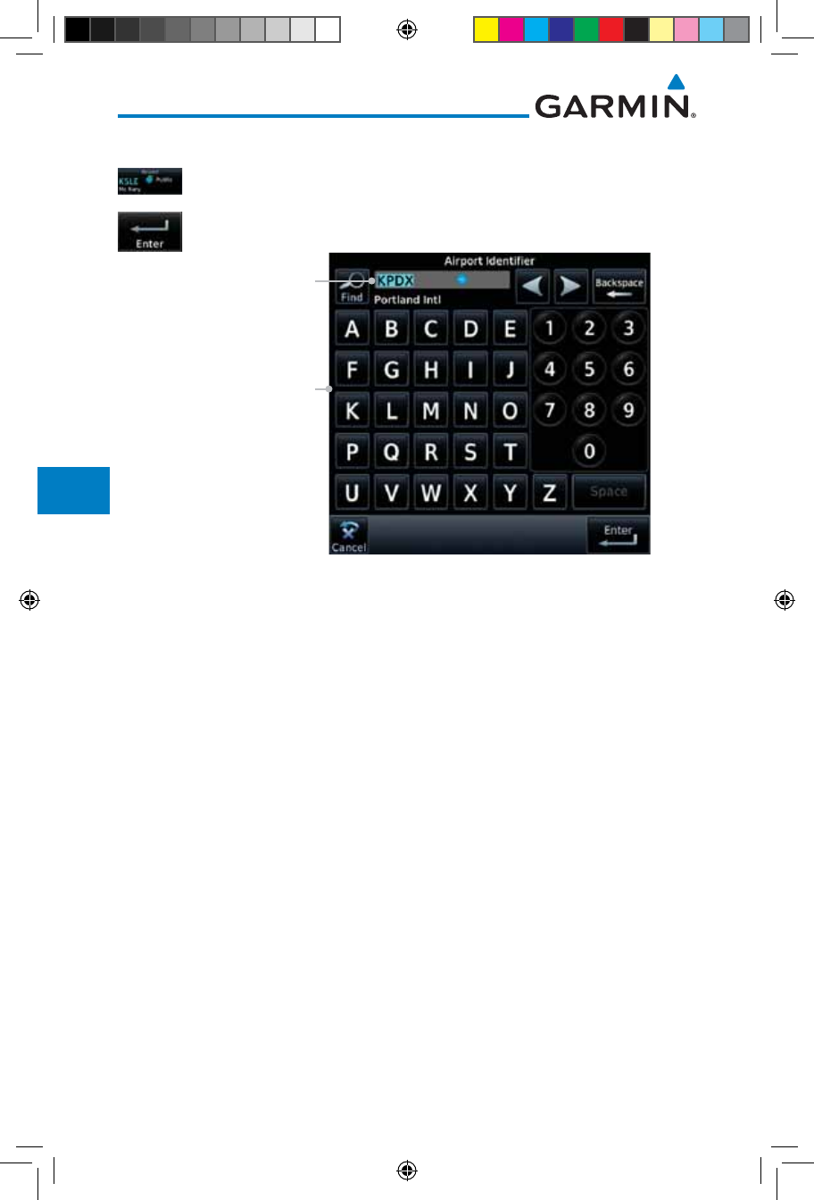
7-4
Garmin GTN 725/750 Pilot’s Guide
190-01007-03 Rev. J
Foreword
Getting
Started
Audio &
Xpdr Ctrl
Com/Nav
FPL
Direct-To
Proc
Charts
Wpt Info
Map
Traffic
Terrain
Weather
Nearest
Services/
Music
Utilities
System
Messages
Symbols
Appendix
Index
7.1.1 Airport Selection
1. Touch the Airport selection key to select another airport.
2. Select the desired airport identifier with the keypad and touch
Enter.
Selected Airport
Touch to Select Airport
Figure 7-3 Airport Identifier Selection
190-01007-03-Final.indb 4 7/9/2015 2:07:21 PM
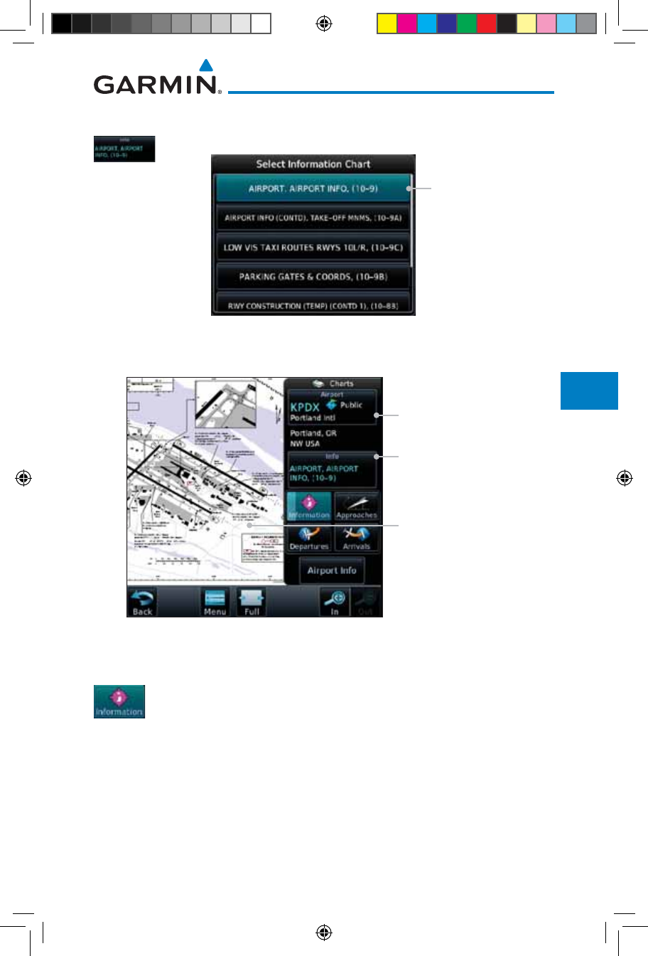
7-5190-01007-03 Rev. J
Garmin GTN 725/750 Pilot’s Guide
Foreword
Getting
Started
Audio &
Xpdr Ctrl
Com/Nav
FPL
Direct-To
Proc
Charts
Wpt Info
Map
Traffic
Terrain
Weather
Nearest
Services/
Music
Utilities
System
Messages
Symbols
Appendix
Index
7.1.2 Info
1. Touch the Info key to select the specific information chart.
Touch To View Selected
Airport Info
Figure 7-4 Airport Info Selection
2. Touch an item from the list to view the chart.
Touch To View Selected
Airport Info List
Selected Airport
Detailed View Of
Selected Airport Info
Figure 7-5 Airport Info Selection Detail
7.1.3 Information
1. Touch the Information key.
2. View the available airport information charts.
190-01007-03-Final.indb 5 7/9/2015 2:07:21 PM
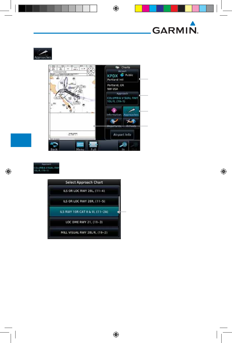
7-6
Garmin GTN 725/750 Pilot’s Guide
190-01007-03 Rev. J
Foreword
Getting
Started
Audio &
Xpdr Ctrl
Com/Nav
FPL
Direct-To
Proc
Charts
Wpt Info
Map
Traffic
Terrain
Weather
Nearest
Services/
Music
Utilities
System
Messages
Symbols
Appendix
Index
7.1.4 Approaches
1. Touch the Approaches key to view available approaches.
Touch To View
Approach List
Selected Airport
Detailed View Of
Selected Approach
Touch To View
Approach Charts
Figure 7-6 Approach Detail
2. Touch the Approach key to select an approach chart.
Touch To View Approach Chart
Figure 7-7 Approach List
3. Touch the desired approach to view detailed information.
190-01007-03-Final.indb 6 7/9/2015 2:07:21 PM
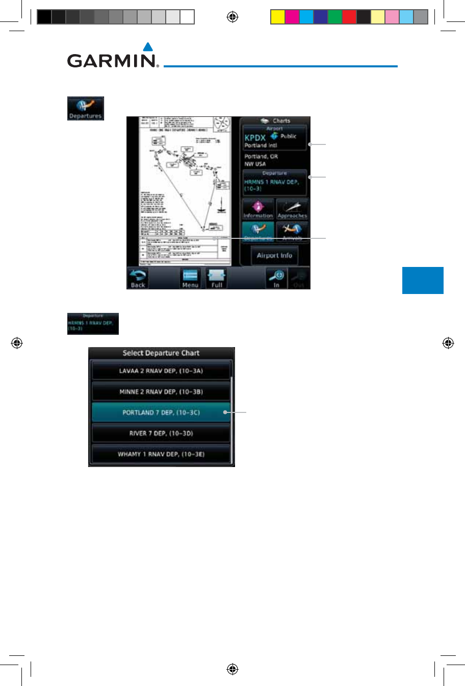
7-7190-01007-03 Rev. J
Garmin GTN 725/750 Pilot’s Guide
Foreword
Getting
Started
Audio &
Xpdr Ctrl
Com/Nav
FPL
Direct-To
Proc
Charts
Wpt Info
Map
Traffic
Terrain
Weather
Nearest
Services/
Music
Utilities
System
Messages
Symbols
Appendix
Index
7.1.5 Departures
1. Touch the Departures key to view available departures.
Touch To View
Departure List
Selected Airport
Detailed View Of
Selected Departure
Figure 7-8 Departure Detail
2. Touch the Departure key to change the selected Departure
chart.
Touch To View The Departure Chart
Figure 7-9 Departure List
3. Touch the desired departure to view detailed information.
190-01007-03-Final.indb 7 7/9/2015 2:07:21 PM
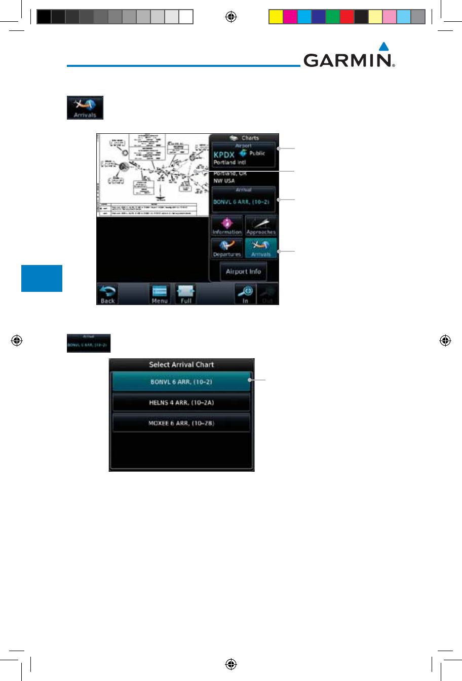
7-8
Garmin GTN 725/750 Pilot’s Guide
190-01007-03 Rev. J
Foreword
Getting
Started
Audio &
Xpdr Ctrl
Com/Nav
FPL
Direct-To
Proc
Charts
Wpt Info
Map
Traffic
Terrain
Weather
Nearest
Services/
Music
Utilities
System
Messages
Symbols
Appendix
Index
7.1.6 Arrivals
1. Touch the Arrivals key to view available arrivals.
Touch To View
Arrival Chart List
Selected Airport
Detailed View Of
Selected Arrival
Touch To View
Arrival Charts
Figure 7-10 Arrival Detail
2. Touch the Arrival key to change the selected Arrival chart.
Touch To View Selected
Arrival Info
Figure 7-11 Arrival List
3. Touch the desired arrival to view detailed information.
190-01007-03-Final.indb 8 7/9/2015 2:07:22 PM
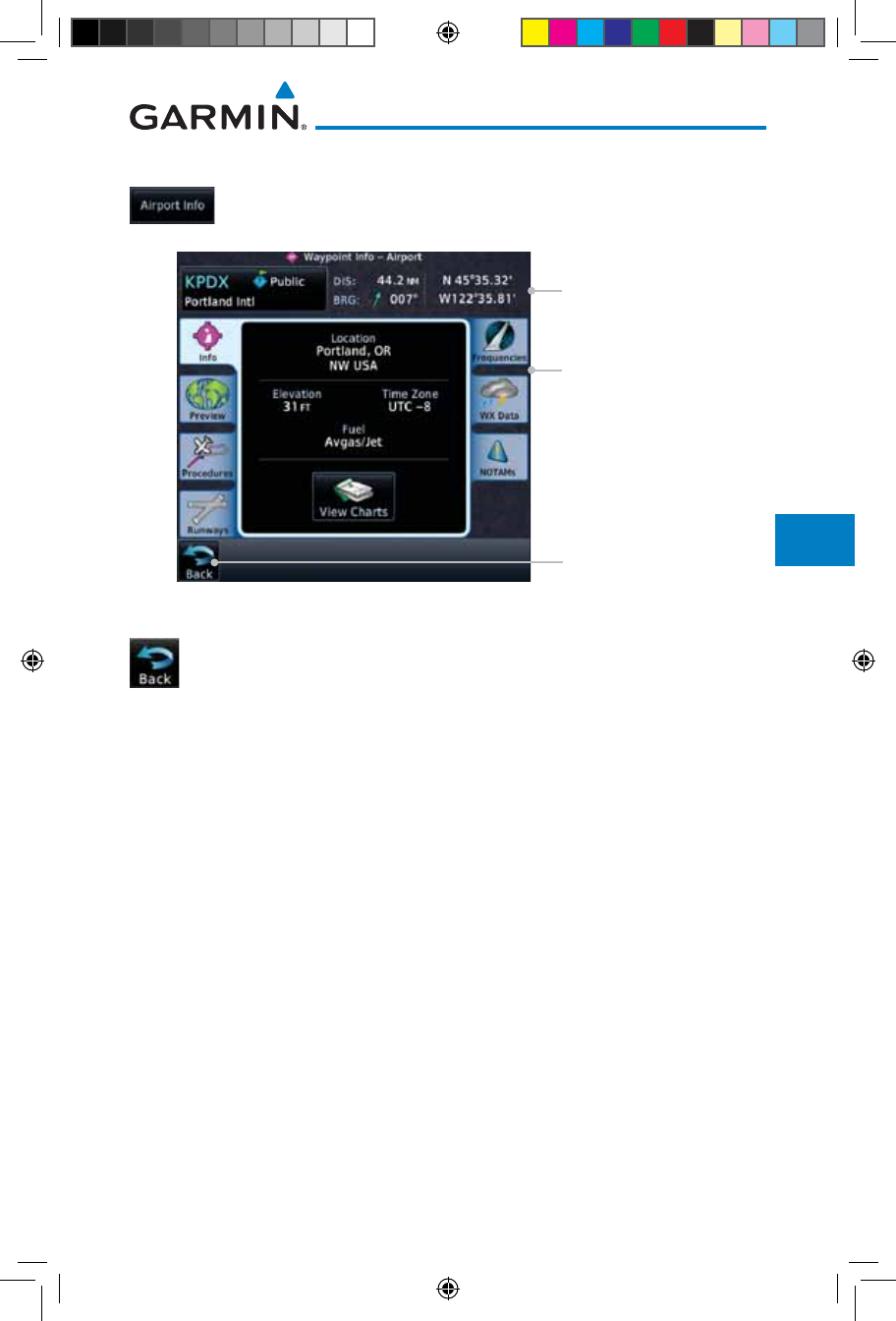
7-9190-01007-03 Rev. J
Garmin GTN 725/750 Pilot’s Guide
Foreword
Getting
Started
Audio &
Xpdr Ctrl
Com/Nav
FPL
Direct-To
Proc
Charts
Wpt Info
Map
Traffic
Terrain
Weather
Nearest
Services/
Music
Utilities
System
Messages
Symbols
Appendix
Index
7.1.7 Airport Info
1. Touch the Airport Info key to view the Waypoint Info for the
selected airport.
Touch Tabs To View
More Details
Selected Airport Info
Touch To Return To
Charts Page
Figure 7-12 Selected Airport Detail
2. Touch the Back key to return to the Charts page.
190-01007-03-Final.indb 9 7/9/2015 2:07:22 PM
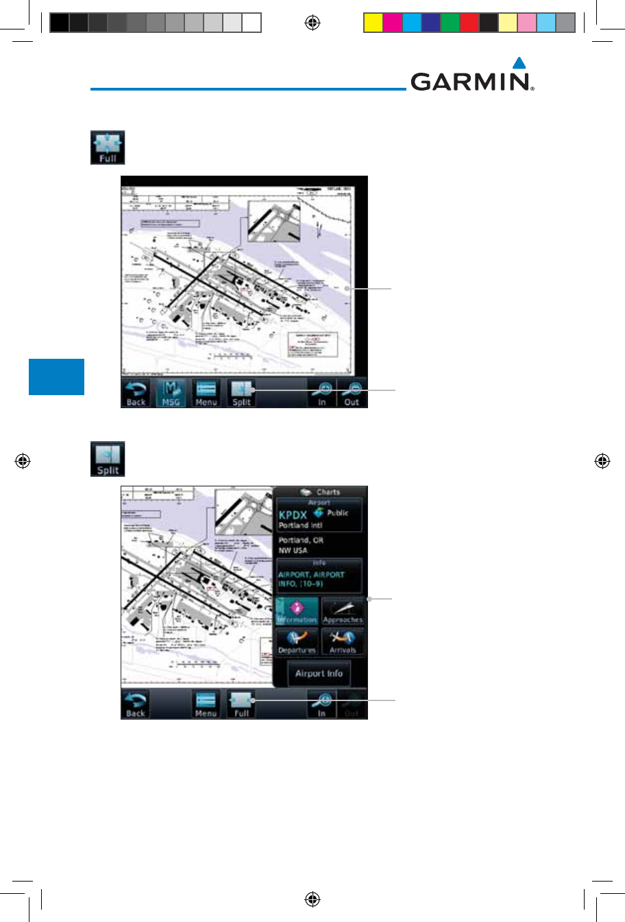
7-10
Garmin GTN 725/750 Pilot’s Guide
190-01007-03 Rev. J
Foreword
Getting
Started
Audio &
Xpdr Ctrl
Com/Nav
FPL
Direct-To
Proc
Charts
Wpt Info
Map
Traffic
Terrain
Weather
Nearest
Services/
Music
Utilities
System
Messages
Symbols
Appendix
Index
7.1.8 Full/Split Screen
1. Touch the Full key to display a full screen view of the current
chart page.
Full Chart Page View
Touch To Return To
Split Chart Page View
Figure 7-13 Full View of Chart Page
2. Touch the Split key to display a view of the current chart page
split between the chart detail and chart page controls.
Split Chart Page View
Touch To Display Full
Chart Page View
Figure 7-14 Split View of Chart Page
190-01007-03-Final.indb 10 7/9/2015 2:07:22 PM
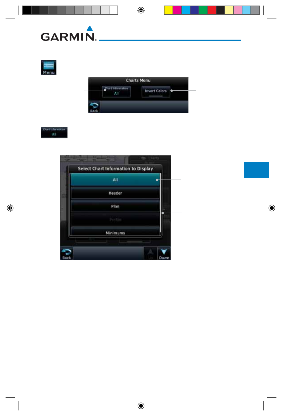
7-11190-01007-03 Rev. J
Garmin GTN 725/750 Pilot’s Guide
Foreword
Getting
Started
Audio &
Xpdr Ctrl
Com/Nav
FPL
Direct-To
Proc
Charts
Wpt Info
Map
Traffic
Terrain
Weather
Nearest
Services/
Music
Utilities
System
Messages
Symbols
Appendix
Index
7.2 Chart Menu Options
1. From the Charts page, touch the Menu key.
Touch To Display
Normal Or Inverted
Chart Colors
Touch To Select
Chart Layer
Figure 7-15 Chart Options
2. Touch the Chart Information key to select a Chart Layer.
Chart Layers are only available with ChartView.
Current Selected
Chart Layer
Touch To Select
Chart Layer
Figure 7-16 Select From Chart Layer List
3. Touch the desired selection to display the selected Chart Layer.
190-01007-03-Final.indb 11 7/9/2015 2:07:22 PM
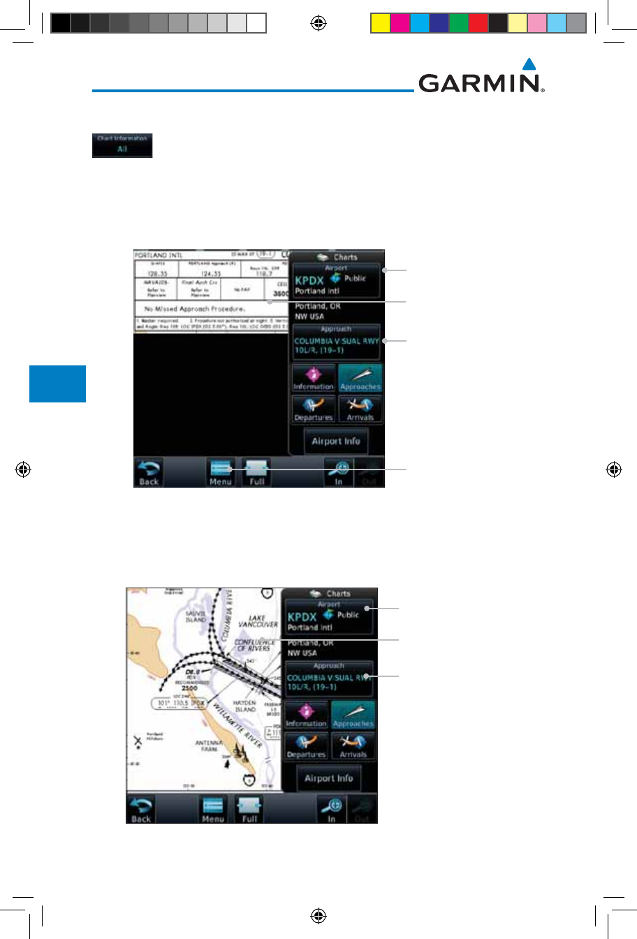
7-12
Garmin GTN 725/750 Pilot’s Guide
190-01007-03 Rev. J
Foreword
Getting
Started
Audio &
Xpdr Ctrl
Com/Nav
FPL
Direct-To
Proc
Charts
Wpt Info
Map
Traffic
Terrain
Weather
Nearest
Services/
Music
Utilities
System
Messages
Symbols
Appendix
Index
7.2.1 Chart Layers - All
Touch the All key to view the composite of layers available
for the selected chart.
7.2.2 Chart Layers - Header
Touch the Header selection from the Chart Layer list to view
the header information for the selected approach chart.
Selected Approach
Selected Airport
Detailed View Of
Selected Header
Touch Menu To
Select Layers
Figure 7-17 Header View of Chart for the Selected Approach
7.2.3 Chart Layers - Plan
Touch the Plan selection from the Chart Layer list to view the
Plan View for the selected approach chart.
Selected Approach
Selected Airport
Detailed Plan View Of
Selected Approach
Figure 7-18 Plan View of Chart for the Selected Approach
190-01007-03-Final.indb 12 7/9/2015 2:07:22 PM
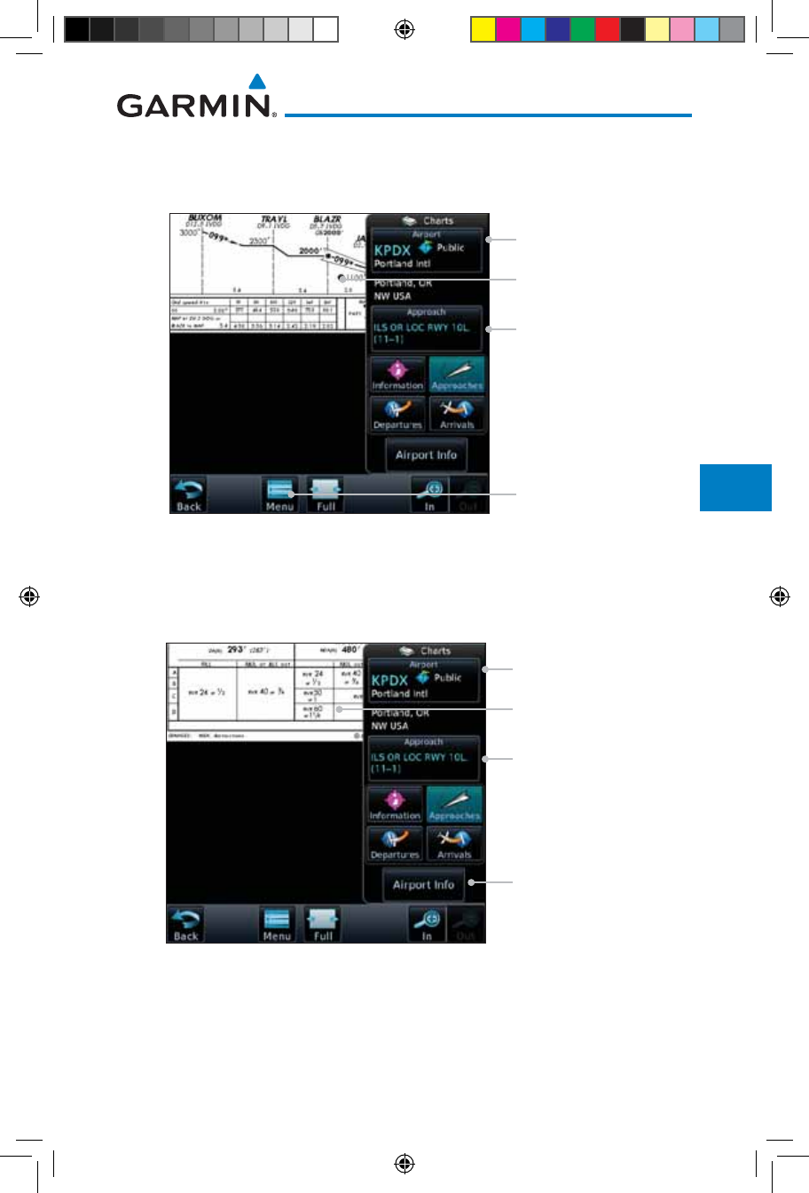
7-13190-01007-03 Rev. J
Garmin GTN 725/750 Pilot’s Guide
Foreword
Getting
Started
Audio &
Xpdr Ctrl
Com/Nav
FPL
Direct-To
Proc
Charts
Wpt Info
Map
Traffic
Terrain
Weather
Nearest
Services/
Music
Utilities
System
Messages
Symbols
Appendix
Index
7.2.4 Chart Layers - Profile
Touch the Profile selection from the Chart Layer list to view
the vertical profile of the selected approach.
Selected Approach
Selected Airport
Detailed View Of
Selected Profile
Touch To Display
Chart Info Options
Figure 7-19 Profile View of Chart for the Selected Approach
7.2.5 Chart Layers - Minimums
Touch the Minimums selection from the Chart Layer list to
view the minimums for the selected approach.
Selected Approach
Selected Airport
Detailed View Of
Selected Minimums
Touch To Display
Minimums
Figure 7-20 Minimums View of Chart for the Selected Approach
190-01007-03-Final.indb 13 7/9/2015 2:07:23 PM
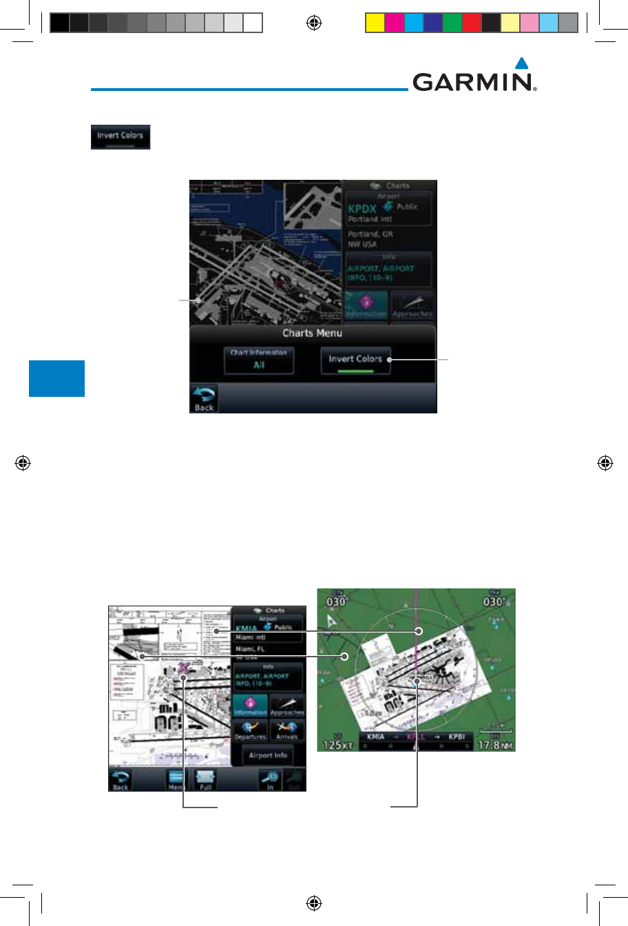
7-14
Garmin GTN 725/750 Pilot’s Guide
190-01007-03 Rev. J
Foreword
Getting
Started
Audio &
Xpdr Ctrl
Com/Nav
FPL
Direct-To
Proc
Charts
Wpt Info
Map
Traffic
Terrain
Weather
Nearest
Services/
Music
Utilities
System
Messages
Symbols
Appendix
Index
7.2.6 Invert Colors
While viewing the Charts Menu, touch the Invert Colors key
to show an inverted color view of the display that enhances
low light viewing.
Inverted Color
Chart Page View
Touch For
Inverted Color
Chart Page View
Figure 7-21 Inverted Chart Colors View
7.2.7 Geo-Referenced Aircraft Position
The geo-referenced aircraft position is placed on the chart when a position is
established. On the Map page, the chart and geo-referenced position are shown
when the aircraft is in the air (such as, speed is greater than 30 knots). When
a chart is viewed on the Map page, areas of the chart that do not support geo-
referencing, such as expanded details and text blocks, are removed. Typically, SIDs
and STARs are not geo-referenced and thus will not typically display the ownship
symbol on those charts.
Geo-Referenced Aircraft Position
Figure 7-22 Areas of Chart Info Removed For Map Overlay and Geo-Reference
190-01007-03-Final.indb 14 7/9/2015 2:07:23 PM
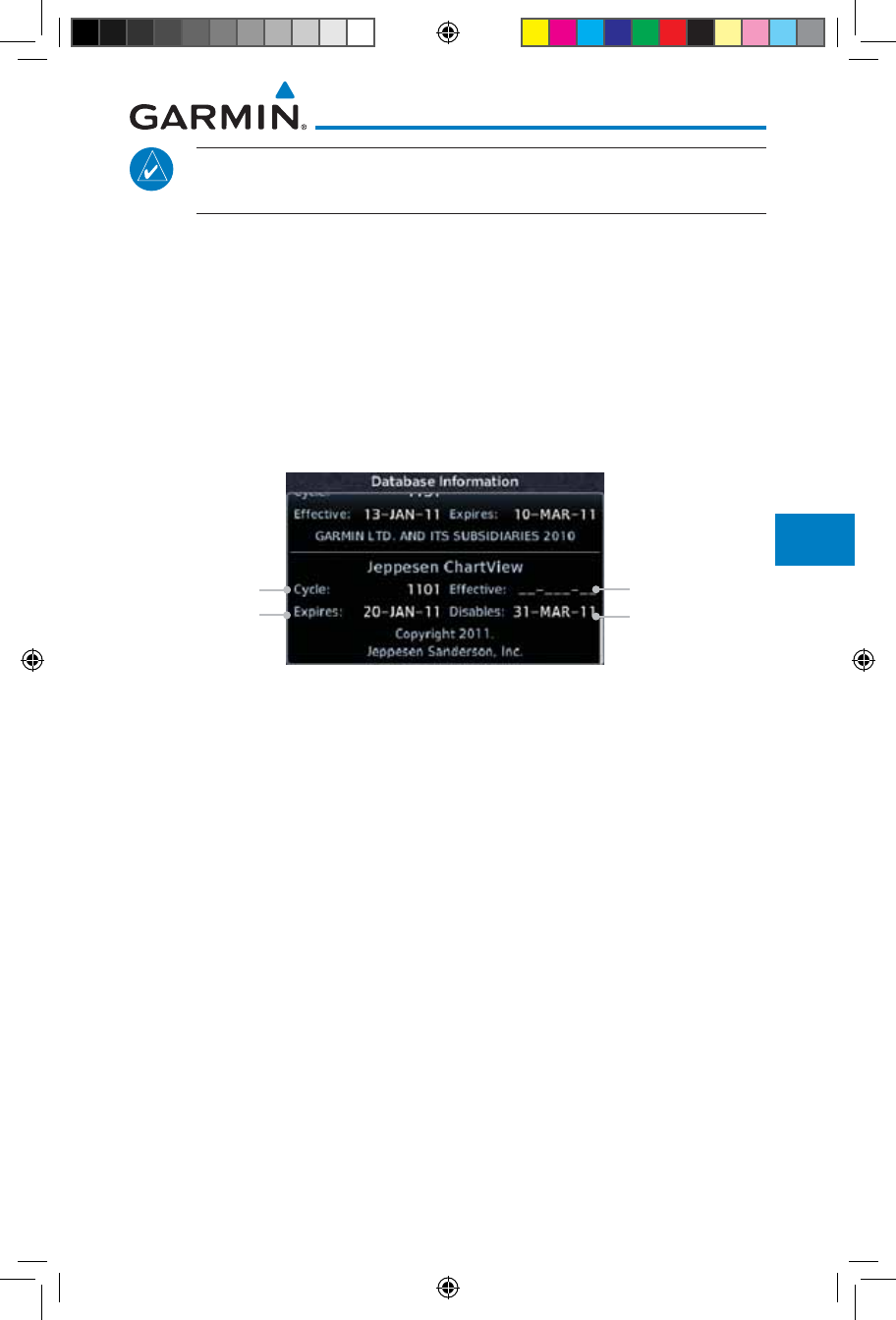
7-15190-01007-03 Rev. J
Garmin GTN 725/750 Pilot’s Guide
Foreword
Getting
Started
Audio &
Xpdr Ctrl
Com/Nav
FPL
Direct-To
Proc
Charts
Wpt Info
Map
Traffic
Terrain
Weather
Nearest
Services/
Music
Utilities
System
Messages
Symbols
Appendix
Index
NOTE: The entire ownship symbol must be able to fit within the
displayed chart area before it will be drawn.
7.3 ChartView Cycle Number and Revision
The ChartView database is revised every 14 days. Charts are still viewable
during a period that extends from the cycle expiration date to the disables date.
ChartView is disabled 70 days after the expiration date and is no longer available
for viewing upon reaching the disable date. When turning on the GTN unit, the
Power-up Page indicates the criteria for ChartView availability. An enablement
card that is purchased from Garmin is separate from the Jeppesen database and
is required to enable ChartView. Jeppeson does not provide the Effective date.
ChartView Cycle Info Not Provided
ChartView
Expiration Date
ChartView Will
Be Disabled On
This Date
Figure 7-23 System Status Database Information for ChartView
The database CYCLE number, EXPIRES, and DISABLES dates of the
ChartView database appear in either white or yellow text. When the ChartView
EXPIRES date is reached, ChartView becomes inoperative 70 days later. This is
shown as the DISABLES date. When the DISABLES date is reached, charts are
no longer available for viewing.
The ChartView database is provided directly from Jeppesen. Refer to Jeppesen
Databases in Appendix A for instructions on revising the ChartView database.
190-01007-03-Final.indb 15 7/9/2015 2:07:23 PM
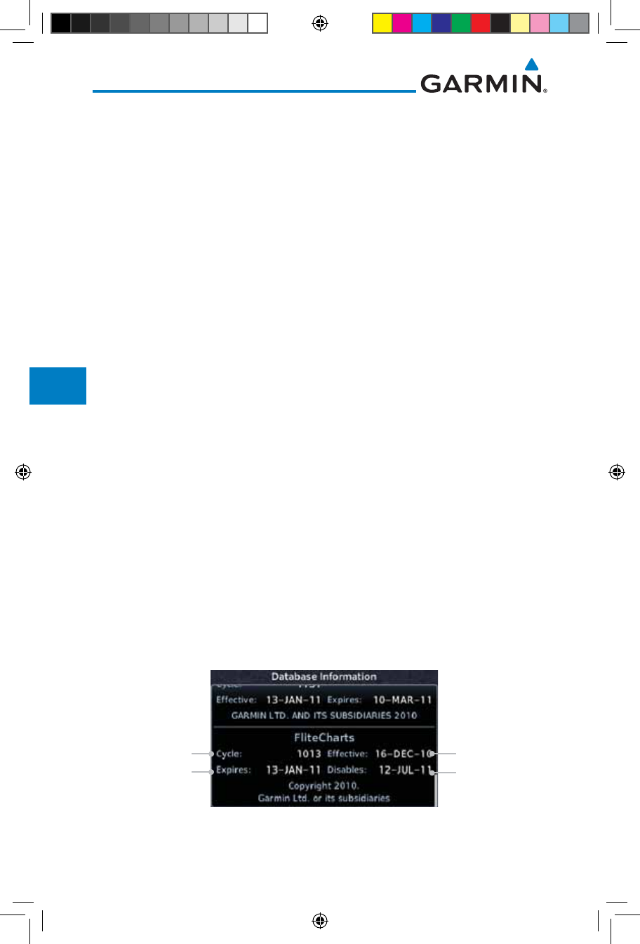
7-16
Garmin GTN 725/750 Pilot’s Guide
190-01007-03 Rev. J
Foreword
Getting
Started
Audio &
Xpdr Ctrl
Com/Nav
FPL
Direct-To
Proc
Charts
Wpt Info
Map
Traffic
Terrain
Weather
Nearest
Services/
Music
Utilities
System
Messages
Symbols
Appendix
Index
7.4 FliteCharts®
FliteCharts® resemble the paper version of National Aeronautical Charting Office
(NACO) terminal procedures charts. The charts are displayed with high-resolution
and in color for applicable charts.
Garmin FliteCharts is an electronic version of the National Aeronautical
Navigation Services Charts (AeroNav Services), which was formerly NACO.
FliteCharts lets pilots quickly find and view all AeroNav Services Departure
Procedures (DP), Standard Terminal Arrival Routes (STARs), approach charts, and
airport diagrams. If the current approach is known, the GTN 7XX automatically
selects the correct chart based on the flight plan. Pilots will have access to all
approach plates currently published by AeroNav, which encompasses over 15,000
charts and over 2,900 airports in the U.S. FliteCharts updates are available from
Garmin every 28 days, and the new geo-referenced capability will be included with
the regular updates.
FliteCharts database subscription is available from Garmin. Available data
includes:
• Arrivals (STAR)
• Departure Procedures (DP)
• Approaches
• Airport Diagrams
7.4.1 FliteCharts Cycle Number and Revision
FliteCharts data is revised every 28 days. Charts are still viewable during a
period that extends from the cycle expiration date to the disables date. FliteCharts
is disabled 180 days after the expiration date and are no longer available for viewing
upon reaching the disables date. When turning on the GTN 7XX, the Power-up
page indicates the criteria for chart availability. These indications are whether the
databases are not configured, not available, current, out of date, or disabled.
FliteCharts Cycle
Date FliteCharts
Is Effective
FliteCharts
Expiration Date FliteCharts Will
Be Disabled On
This Date
Figure 7-24 System Status Database Information for FliteCharts
190-01007-03-Final.indb 16 7/9/2015 2:07:23 PM
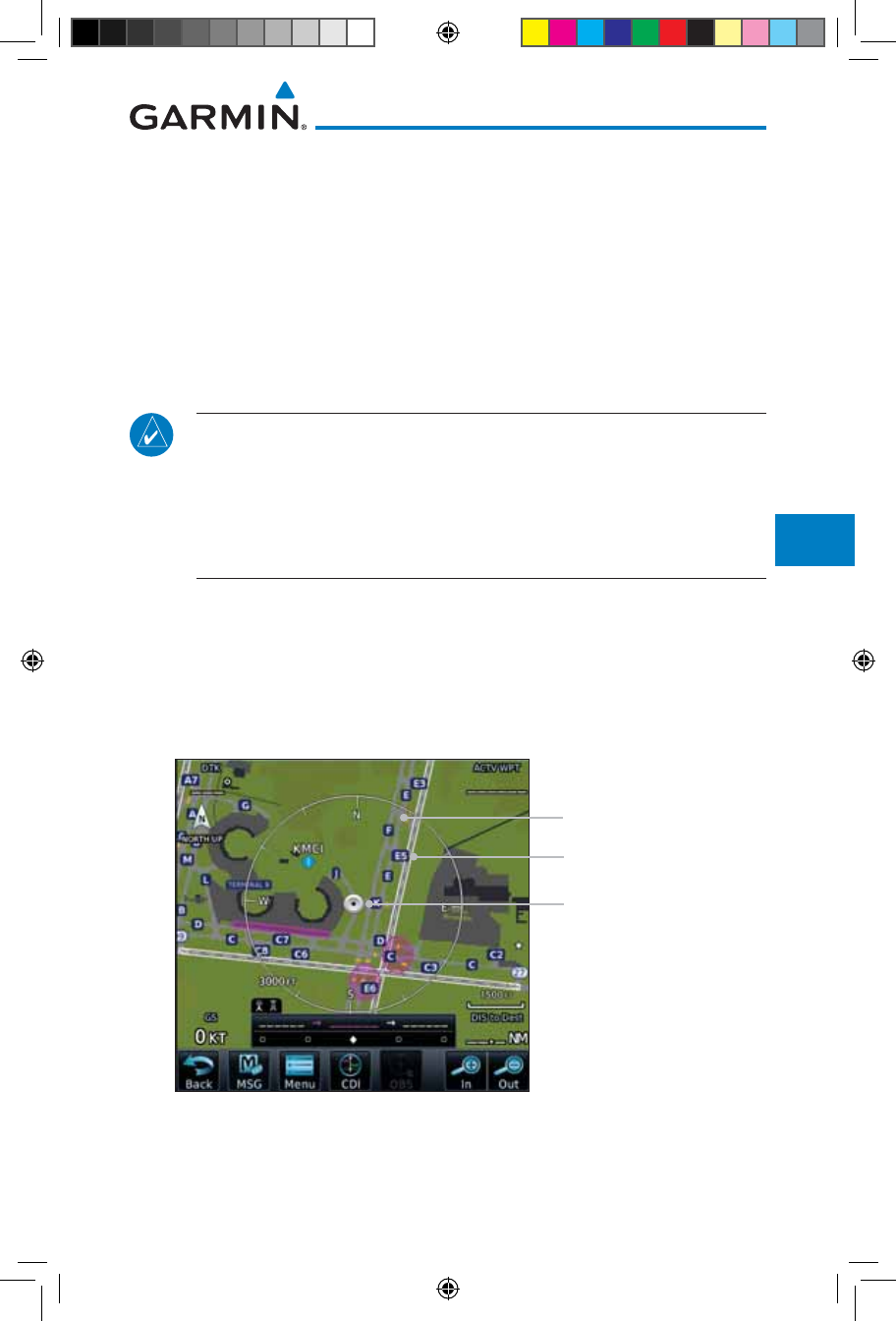
7-17190-01007-03 Rev. J
Garmin GTN 725/750 Pilot’s Guide
Foreword
Getting
Started
Audio &
Xpdr Ctrl
Com/Nav
FPL
Direct-To
Proc
Charts
Wpt Info
Map
Traffic
Terrain
Weather
Nearest
Services/
Music
Utilities
System
Messages
Symbols
Appendix
Index
7.5 SafeTaxi®
SafeTaxi® is an enhanced feature that gives greater map detail when zooming
in on airports. The airport display on the map reveals runways with numbers,
taxiways with identifying letters/numbers,
airport Hot Spots,
and airport
landmarks including ramps, buildings, control towers, and other prominent
features. Resolution is greater at lower map ranges (zooming in). When the
aircraft location is within the screen boundary, including within SafeTaxi ranges,
an airplane symbol is shown on any of the navigation map views for enhanced
position awareness.
NOTE: Do not use SafeTaxi or Chartview functions as the basis for
ground maneuvering. SafeTaxi and Chartview functions do not comply
with the requirements of AC 20-159 and are not qualified to be used as
an airport moving map display (AMMD). SafeTaxi and Chartview are to
be used by the flight crew to orient themselves on the airport surface to
improve pilot situational awareness during ground operations.
Designated Hot Spots are recognized at airports with many intersecting
taxiways and runways, and/or complex ramp areas. Airport Hot Spots are
outlined to caution pilots of areas on an airport surface where positional
awareness confusion or runway incursions happen most often. Hot Spots are
defined with a magenta circle or outline around the region of possible confusion.
Taxiway Identification
Taxiway Detail
Aircraft Position
Figure 7-25 SafeTaxi Depiction on the Navigation Map Page
190-01007-03-Final.indb 17 7/9/2015 2:07:23 PM
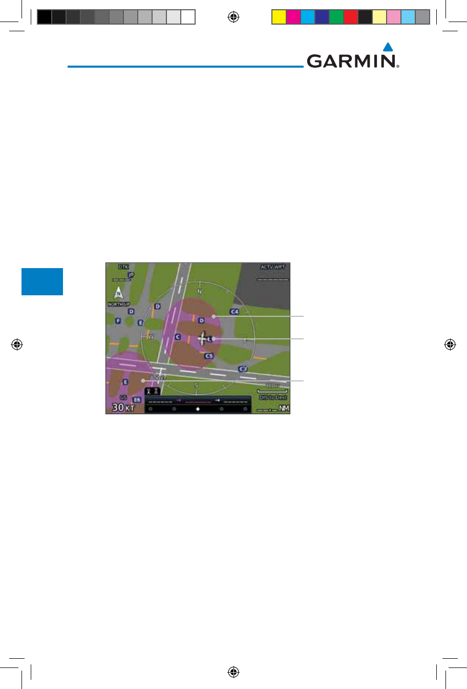
7-18
Garmin GTN 725/750 Pilot’s Guide
190-01007-03 Rev. J
Foreword
Getting
Started
Audio &
Xpdr Ctrl
Com/Nav
FPL
Direct-To
Proc
Charts
Wpt Info
Map
Traffic
Terrain
Weather
Nearest
Services/
Music
Utilities
System
Messages
Symbols
Appendix
Index
7.5.1 Using SafeTaxi®
Any map page that displays the navigation view can also show the SafeTaxi®
airport layout within the maximum configured range. Charts and SafeTaxi are
mutually exclusive. So, to view SafeTaxi and Hot Spots, the Charts feature must
be turned off. Charts are displayed when the aircraft is in the air, but when on
the ground, charts are removed and SafeTaxi will be shown automatically.
During ground operations the aircraft’s position is displayed in reference to
taxiways, runways, and airport features. The nose of the ownship symbol, not
the center, depicts the current location of the aircraft.
7.5.2 Hot Spot Information
Hot Spot locations are identified by a magenta circle or outline.
Hot Spot Location
Aircraft Location
Hot Spot Location
Figure 7-26 SafeTaxi Hot Spot Depiction
190-01007-03-Final.indb 18 7/9/2015 2:07:24 PM

7-19190-01007-03 Rev. J
Garmin GTN 725/750 Pilot’s Guide
Foreword
Getting
Started
Audio &
Xpdr Ctrl
Com/Nav
FPL
Direct-To
Proc
Charts
Wpt Info
Map
Traffic
Terrain
Weather
Nearest
Services/
Music
Utilities
System
Messages
Symbols
Appendix
Index
7.5.3 SafeTaxi® Cycle Number and Revision
The SafeTaxi database is revised every 56 days. SafeTaxi is always available
for use after the expiration date. When turning on the GTN 7XX, the Power-up
Page indicates whether the databases are current, out of date, or not available.
The Power-up Page shows the SafeTaxi database is current when the “SafeTaxi
Expires” date is shown in white. When the SafeTaxi cycle has expired, the
“SafeTaxi Expires” date appears in yellow. The message “unknown” appears in
white if no SafeTaxi data is available on the database card.
The SafeTaxi Region, Version, Cycle, Effective date and Expires date of the
database cycle can also be found on the System - System Status page. SafeTaxi
information appears in white and yellow text. The EFFECTIVE date appears in
white when data is current and in yellow when the current date is before the
effective date. The EXPIRES date appears in white when data is current and in
yellow when expired. SafeTaxi REGION NOT AVAILABLE appears in white if
SafeTaxi data is not available on the database card.
190-01007-03-Final.indb 19 7/9/2015 2:07:24 PM

7-20
Garmin GTN 725/750 Pilot’s Guide
190-01007-03 Rev. J
Foreword
Getting
Started
Audio &
Xpdr Ctrl
Com/Nav
FPL
Direct-To
Proc
Charts
Wpt Info
Map
Traffic
Terrain
Weather
Nearest
Services/
Music
Utilities
System
Messages
Symbols
Appendix
Index
This page intentionally left blank
190-01007-03-Final.indb 20 7/9/2015 2:07:24 PM
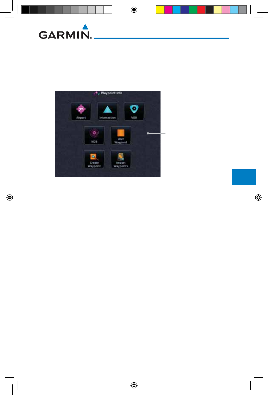
8-1190-01007-03 Rev. J
Garmin GTN 725/750 Pilot’s Guide
Foreword
Getting
Started
Audio &
Xpdr Ctrl
Com/Nav
FPL
Direct-To
Proc
Charts
Wpt Info
Map
Traffic
Terrain
Weather
Nearest
Services/
Music
Utilities
System
Messages
Symbols
Appendix
Index
8 WAYPOINT INFO
The Waypoint Info function allows you to view information about the selected
waypoint. The Waypoint Info page can be reached from the Home page, selected
from a flight plan, or selected from the Nearest page.
Touch Key to Display
Waypoint Type
Figure 8-1 Waypoint Info Page
190-01007-03-Final.indb 1 7/9/2015 2:07:24 PM
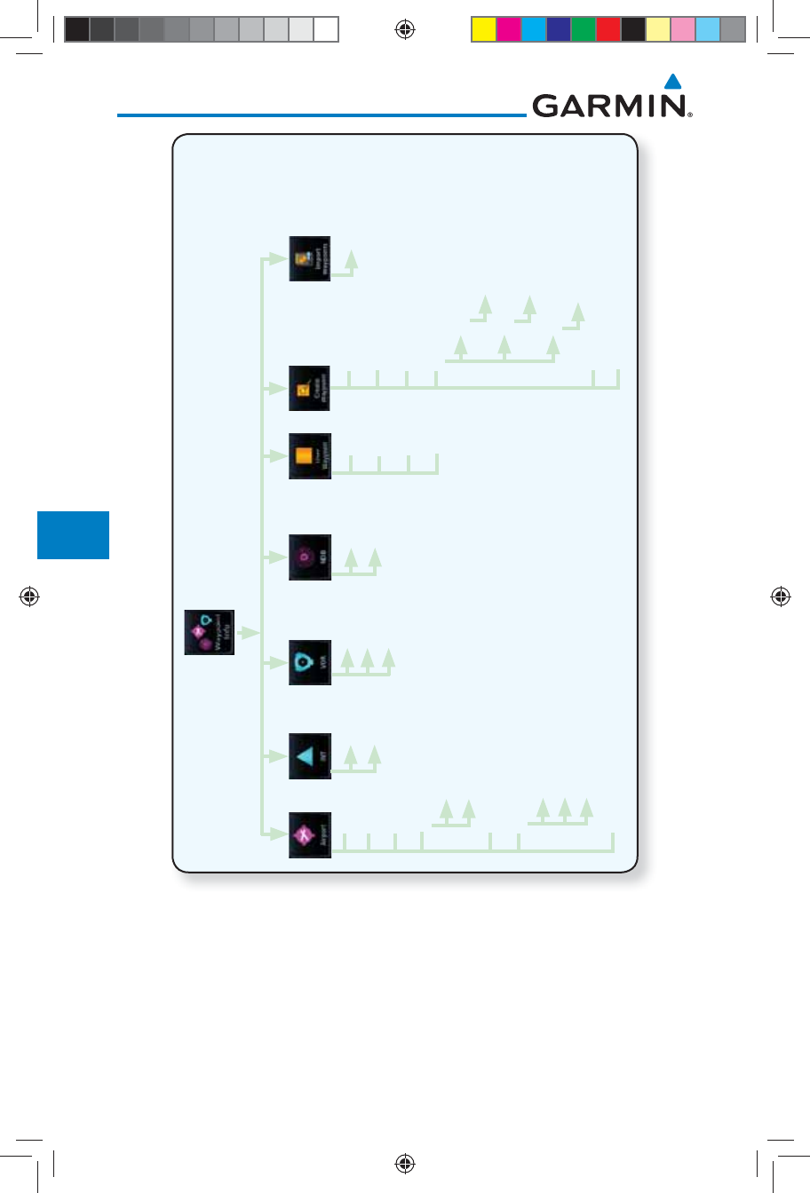
8-2
Garmin GTN 725/750 Pilot’s Guide
190-01007-03 Rev. J
Foreword
Getting
Started
Audio &
Xpdr Ctrl
Com/Nav
FPL
Direct-To
Proc
Charts
Wpt Info
Map
Traffic
Terrain
Weather
Nearest
Services/
Music
Utilities
System
Messages
Symbols
Appendix
Index
Name
View All
Delete
Edit
Select INT
Preview
Select VOR
Preview
Frequency
Select NDB
Preview
Name
Comment
Temporary?
Create
Lat/Lon
Radial/Radial
Radial/Dist
Position Type
Ref Wpt - Rad
Lat/Lon
Ref Wpt - Rad - Dis
Preview
Info
Preview
Procedures
Runways
Runway
PCL
Frequencies
Metars
Forecast
TAF
Wx Data
NOTAMs
User Wpt Import
Figure 8-2 Waypoint Info Functional Diagram
190-01007-03-Final.indb 2 7/9/2015 2:07:24 PM
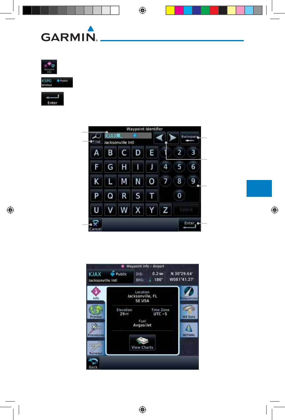
8-3190-01007-03 Rev. J
Garmin GTN 725/750 Pilot’s Guide
Foreword
Getting
Started
Audio &
Xpdr Ctrl
Com/Nav
FPL
Direct-To
Proc
Charts
Wpt Info
Map
Traffic
Terrain
Weather
Nearest
Services/
Music
Utilities
System
Messages
Symbols
Appendix
Index
8.1 Waypoint Selection
1. Touch the Waypoint Info key and then touch the desired
waypoint type (Airport, INT, VOR, etc).
2. Touch the waypoint identifier.
3. The waypoint identifier selection page will be shown and the
waypoint identifier field will be active for selection. Touch the
required keys on the alphanumeric keypad to select the desired
waypoint identifier and then touch the Enter key.
Airport Identifier Backspace
Key Clears
Wpt Ident
Alphanumeric
Keypad
Find Key Displays
Waypoint Search
Touch Enter
After Selecting
Ident
Cursor
Movement
Keys
Touch To Cancel
Selection And
Return To
Previous Page
Figure 8-3 Waypoint Ident Selection
4. The information page for the selected waypoint will be
displayed.
Figure 8-4 Waypoint Ident Selection Result
190-01007-03-Final.indb 3 7/9/2015 2:07:25 PM
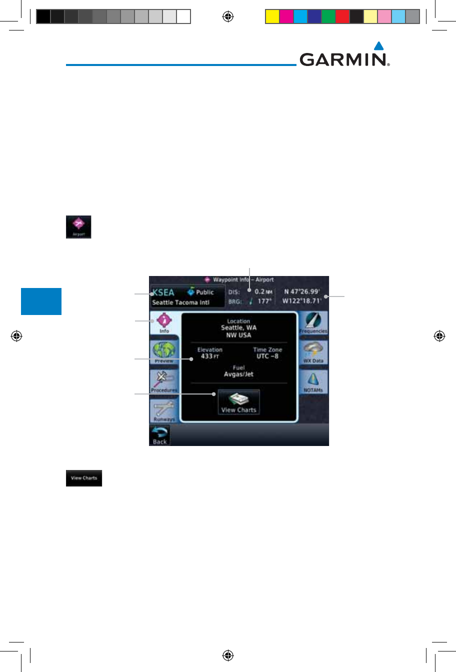
8-4
Garmin GTN 725/750 Pilot’s Guide
190-01007-03 Rev. J
Foreword
Getting
Started
Audio &
Xpdr Ctrl
Com/Nav
FPL
Direct-To
Proc
Charts
Wpt Info
Map
Traffic
Terrain
Weather
Nearest
Services/
Music
Utilities
System
Messages
Symbols
Appendix
Index
8.2 Airport
The Airport page of the Waypoint Info function provides a variety of detailed
information about the airport.
8.2.1 Info
The upper part of the page shows the airport identifier and type, name, city
and region, the lat/lon coordinates of the airport, and the bearing (and direction
arrow) and distance to the airport from your present position. The center area
shows the airport elevation, fuel availability, and time zone.
1. While viewing the Waypoint Info page, touch the Airport
key.
Distance & Bearing To Airport
From Current Position
Waypoint Info
Page Tab
Airport
Identifier, City,
& Type
Airport
Information
Touch To
View Airport
Charts
Airport
Lat/Lon
Figure 8-5 Waypoint Info Airport Page
2.
Touch the View Charts key to display available charts for the airport.
190-01007-03-Final.indb 4 7/9/2015 2:07:25 PM
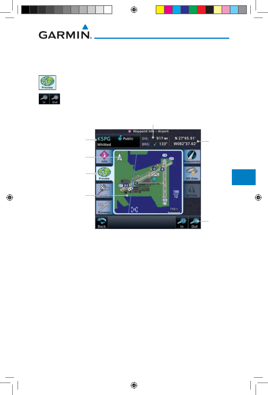
8-5190-01007-03 Rev. J
Garmin GTN 725/750 Pilot’s Guide
Foreword
Getting
Started
Audio &
Xpdr Ctrl
Com/Nav
FPL
Direct-To
Proc
Charts
Wpt Info
Map
Traffic
Terrain
Weather
Nearest
Services/
Music
Utilities
System
Messages
Symbols
Appendix
Index
8.2.2 Preview
The Waypoint Info Airport Preview page provides detailed information about
the selected airport.
1. Touch the Preview tab to view a map of the airport and
surrounding area.
2. Use the In and Out keys to zoom in and out on the Preview
map.
Distance & Bearing To Airport
From Current Position
Waypoint
Preview Page Tab
Airport
Identifier, City,
& Airport Type
Airport Area
Map
Touch & Move
Finger While
Pressing To Pan Map
Airport
Lat/Lon
Touch
To Zoom
Figure 8-6 Waypoint Info Airport Map Page
3. You may touch the map window and while pressing the display
drag your finger to move the map view.
190-01007-03-Final.indb 5 7/9/2015 2:07:25 PM
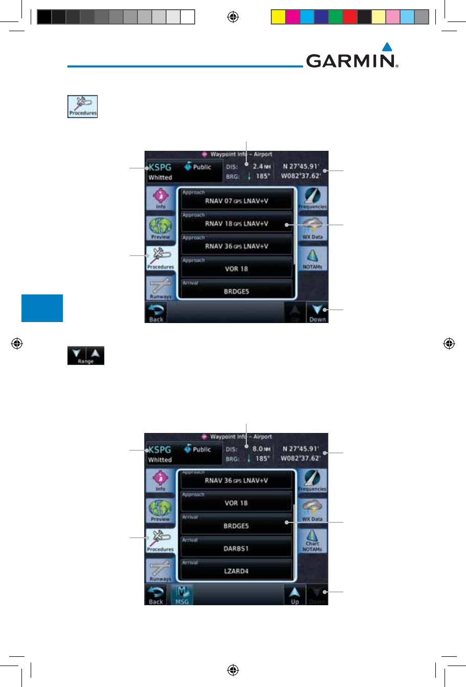
8-6
Garmin GTN 725/750 Pilot’s Guide
190-01007-03 Rev. J
Foreword
Getting
Started
Audio &
Xpdr Ctrl
Com/Nav
FPL
Direct-To
Proc
Charts
Wpt Info
Map
Traffic
Terrain
Weather
Nearest
Services/
Music
Utilities
System
Messages
Symbols
Appendix
Index
8.2.3 Procedures
1. Touch the Procedures page tab to view details about
procedures for the selected airport.
Distance & Bearing To Airport
From Current Position
Procedures
Page Tab
Airport
Identifier, City,
& Airport Type Airport
Lat/Lon
Touch
To Scroll
Approach
Name & Type
Figure 8-7 Waypoint Info Airport Procedures Page
2. Touch the Up and Down keys to view additional procedures,
as needed.
3. Touch one of the procedure keys to select it for the Procedures
function.
Distance & Bearing To Airport
From Current Position
Procedures
Page Tab
Airport
Identifier, City,
& Airport Type Airport
Lat/Lon
Touch
To Scroll
Arrival Name
Figure 8-8 Waypoint Info Airport Arrival Information
190-01007-03-Final.indb 6 7/9/2015 2:07:25 PM
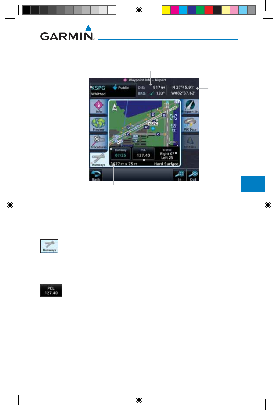
8-7190-01007-03 Rev. J
Garmin GTN 725/750 Pilot’s Guide
Foreword
Getting
Started
Audio &
Xpdr Ctrl
Com/Nav
FPL
Direct-To
Proc
Charts
Wpt Info
Map
Traffic
Terrain
Weather
Nearest
Services/
Music
Utilities
System
Messages
Symbols
Appendix
Index
8.2.4 Runways
Distance & Bearing To Airport
From Current Position
Airport Runways
Page Tab
Airport
Identifier, City,
& Airport Type
Runway Number.
Touch For Detail
Airport
Lat/Lon
Traffic
Pattern Info
Runway
Detail
Runway
Dimensions
Surface
Type
Pilot-
Controlled
Lighting
Freq. Touch
To Place In
Standby.
Figure 8-9 Waypoint Info Airport Runway Information Page
1. Touch the Runways tab to view information about the
available runways for the selected airport. The runway
identifiers, surface type, lighting with Pilot Controlled Lighting
(PCL) frequency, runway size, and Traffic Pattern direction are
shown.
2. Touch the PCL key to load the PCL frequency into the Com
Standby location.
190-01007-03-Final.indb 7 7/9/2015 2:07:25 PM
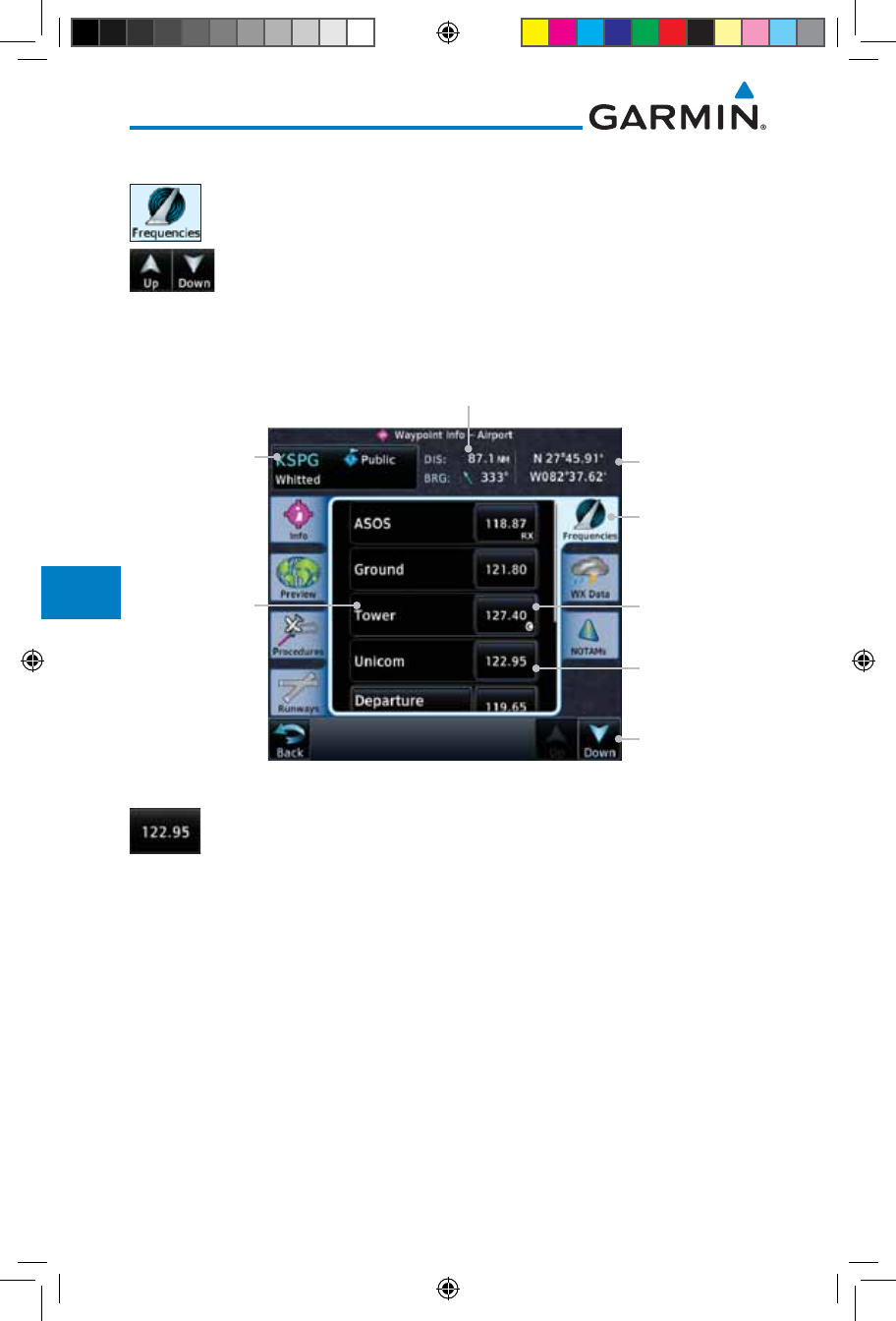
8-8
Garmin GTN 725/750 Pilot’s Guide
190-01007-03 Rev. J
Foreword
Getting
Started
Audio &
Xpdr Ctrl
Com/Nav
FPL
Direct-To
Proc
Charts
Wpt Info
Map
Traffic
Terrain
Weather
Nearest
Services/
Music
Utilities
System
Messages
Symbols
Appendix
Index
8.2.5 Frequencies
1. Touch the Frequencies tab to view details about available
frequencies for the selected airport.
2. Touch the Up and Down keys to view additional frequencies,
as needed. A "c" symbol in a white circle will appear next to
frequencies that also function as the Common Traffic Advisory
Frequency (CTAF).
Distance & Bearing To Airport
From Current Position
Airport
Frequencies
Page Tab
Airport
Identifier, City,
& Airport Type
Frequency Name
Airport
Lat/Lon
Touch
To Scroll
"c" Indicates
CTAF
Touch Frequency
Key To Load Into
Com Standby
Figure 8-10 Waypoint Info Airport Frequency List Page
3. Touch the Frequency key next to the frequency name to
load it as the Com or Nav standby frequency, depending on
frequency type.
190-01007-03-Final.indb 8 7/9/2015 2:07:26 PM
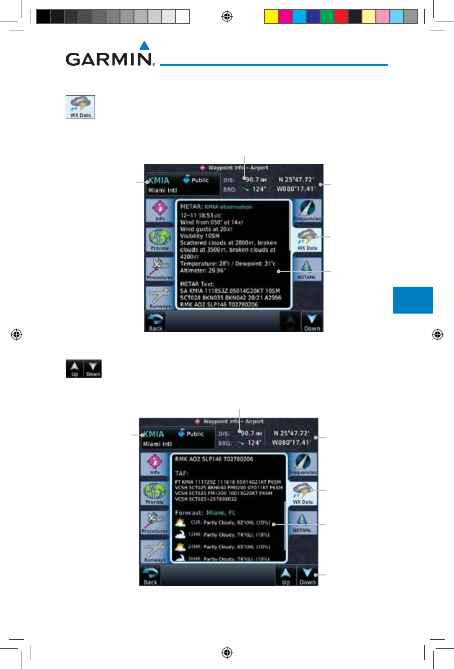
8-9190-01007-03 Rev. J
Garmin GTN 725/750 Pilot’s Guide
Foreword
Getting
Started
Audio &
Xpdr Ctrl
Com/Nav
FPL
Direct-To
Proc
Charts
Wpt Info
Map
Traffic
Terrain
Weather
Nearest
Services/
Music
Utilities
System
Messages
Symbols
Appendix
Index
8.2.6 Weather (WX) Data
1. Touch the WX Data tab next to the center window to view
textual METARs, City Forecast, and TAF weather information
available for the selected airport.
Distance & Bearing To Airport
From Current Position
Airport
Weather
Page Tab
Airport
Identifier, City,
& Airport Type Airport
Lat/Lon
Weather
Information
Figure 8-11 Waypoint Info Airport Weather Page
2. Touch the Up and Down keys to scroll through the Weather
page information.
Distance & Bearing To Airport
From Current Position
Airport
Weather
Page Tab
Airport
Identifier, City,
& Airport Type Airport
Lat/Lon
Touch To
Change Pages
Weather
Forecast
Information
Figure 8-12 Waypoint Info Airport Weather Forecast Page
190-01007-03-Final.indb 9 7/9/2015 2:07:26 PM
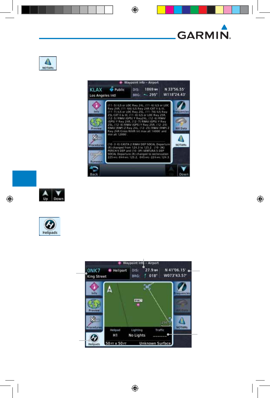
8-10
Garmin GTN 725/750 Pilot’s Guide
190-01007-03 Rev. J
Foreword
Getting
Started
Audio &
Xpdr Ctrl
Com/Nav
FPL
Direct-To
Proc
Charts
Wpt Info
Map
Traffic
Terrain
Weather
Nearest
Services/
Music
Utilities
System
Messages
Symbols
Appendix
Index
8.2.7 NOTAM Pages
1. Touch the NOTAMs tab next to the center window to view
any NOTAMs available for the selected airport. This feature is
supported with ChartView and FIS-B through the GDL 88.
Figure 8-13 Waypoint Info Airport NOTAMs Page
2. Touch the Up and Down keys to view additional information,
as needed.
8.2.8 Helipads
1. Touch the Helipad tab next to the center window to view
any information available for the selected helipad. Helipad
information may not be complete or consistent due to the
data available from the 3rd party sources.
Distance & Bearing To Helipad
From Current Position
Helipad Info
Page Tab
Helipad
Identifier, City,
& Type
Helipad
Information
Helipad
Lat/Lon
Figure 8-14 Helipad Waypoint Info
190-01007-03-Final.indb 10 7/9/2015 2:07:26 PM
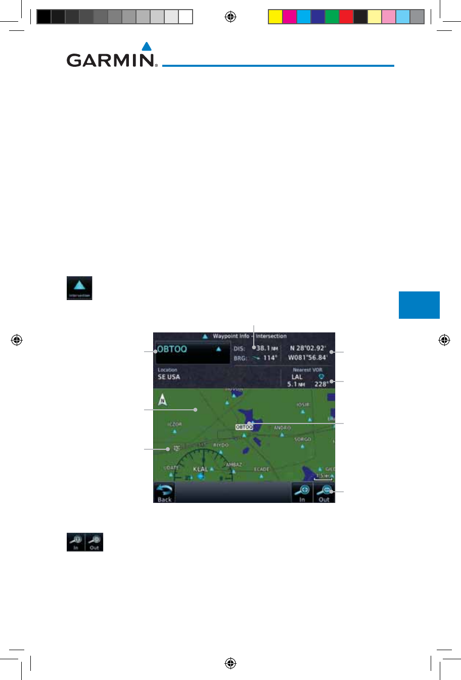
8-11190-01007-03 Rev. J
Garmin GTN 725/750 Pilot’s Guide
Foreword
Getting
Started
Audio &
Xpdr Ctrl
Com/Nav
FPL
Direct-To
Proc
Charts
Wpt Info
Map
Traffic
Terrain
Weather
Nearest
Services/
Music
Utilities
System
Messages
Symbols
Appendix
Index
8.3 Intersection (INT)
The Intersection page of the Waypoint Info function provides a variety
of detailed information about the intersection. The top left area of the page
displays the Intersection identifier and region. The top center area shows the
lat/lon coordinates of the Intersection and the bearing (with direction arrow)
and distance to the Intersection from your present position.
Select another Waypoint by touching the Waypoint Identifier key, entering
the characters for the desired name with the alphanumeric keypad, and then
touching the Enter key. You may also search through the list by touching the
Find key and then choosing from the existing list of waypoints by touching the
desired waypoint from the list.
The center area of the page shows a map with the Intersection in the center.
1. While viewing the Waypoint Info page, touch the Intersection
key.
Distance & Bearing To Intersection
From Current Position
Intersection
Identifier
Intersection
Area Map
Touch & Move
Finger While
Pressing To Pan Map
Intersection
Lat/Lon
Touch
To Zoom
Nearest VOR
Information
Intersection
Symbol &
Identifier
Figure 8-15 Waypoint Info - Intersections
2. Use the In and Out keys to zoom in and out on the map. You
may touch the map window and while lightly pressing the
display, drag your finger to move the map view.
190-01007-03-Final.indb 11 7/9/2015 2:07:26 PM