Gatekeeper Systems W9200 Remote Controlled Locking Wheel User Manual USA TRAINING MANUAL 2007
Gatekeeper Systems, Inc. Remote Controlled Locking Wheel USA TRAINING MANUAL 2007
Contents
- 1. Users Manual Part 1a
- 2. Users Manual Part 1b
- 3. Users Manual Part 2
- 4. Users Manual Part 3
Users Manual Part 1a


GATEKEEPER SYSTEMS, INC
2007 CART CONTAINMENT TRAINING MANUAL
Copyright © 2007
Gatekeeper Systems, Inc.
All rights reserved
Gatekeeper Systems, Inc. 2007 Cart Containment Manual
Rev. 01-25-07
No part of this document may be reproduced or transmitted in any form or by any means whatsoever,
electronically or mechanically, including photocopying and recording, for any purpose without the express written
consent of Gatekeeper Systems, Inc.
Gatekeeper Systems, Inc. and the Gatekeeper Systems, Inc. logo are service marks of Gatekeeper Systems,
Inc..
purchek™ is a registered trademark of Gatekeeper Systems, Inc..
Information in this document is furnished for informational use only, and is subject to change without notice and
does not represent a commitment on the part of Gatekeeper Systems, Inc.
Product names mentioned in this document may be trademarks or registered trademarks of their respective
companies and are hereby acknowledged.
All information contained herein is proprietary and confidential.
GATEKEEPER SYSTEMS INC.
2007 CART CONTAINMENT MANUAL
Table Of Contents
1 Introduction ----------------------------------------------------------------------------------------------------------------------1
2 GS2 System Description and Components----------------------------------------------------------------------------2
3 Pre-Installation Tasks --------------------------------------------------------------------------------------------------------7
The Site Survey 7
Determining the CentralTransmitter Location 8
Determining System Component Requirements 8
Perimeter Antenna Configurations 9
Other Perimeter Antenna Considerations 10
Documenting the Site Survey 11
Sample Site Plans 13
Single Locking Loop 13
Double Saw Cut 14
Twisted Pair And Multiple Lockboxes 15
Single Locking Loop - Over Roof 16
Site Survey Checklist 17
4 Installation---------------------------------------------------------------------------------------------------------------------- 18
Overview 18
Required Tools and Materials 19
Arriving On Site 21
Confirming the CentralTransmitter Location 21
Marking the Antenna Path 21
Saw Cutting the Marked Area 22
Removing Saw Cut Residue 22
Installing the Perimeter Antenna 23
Sealing the Saw Cut 24
Mounting the Central Transmitter 24
CentralTransmitter Front Panel 25
CentralTransmitter Circuit Board 26
Connecting Electrical Power to the CentralTransmitter 29
Calibrating the Central Transmitter 30
Selecting the Transmitter Mode 30
Connecting the Alarm Relays 31
Information Tracker 31
Perimeter Striping 32
Installing the Parking lot Signs 34
Installing the Anti-tilt Bars 36
Installing the GS2 Wheel 36
Installing the Cart-Mounted Signs 37
5 Installation Photographs -------------------------------------------------------------------------------------------------- 38
6 ExitManager-------------------------------------------------------------------------------------------------------------------- 55
7 Indoor Cart Containment Systems ------------------------------------------------------------------------------------- 58
System Layout 58
System Layout with EAS System 59
8 Store Training ----------------------------------------------------------------------------------------------------------------- 60
Training the Store Personnel 60
GS2 TRAINING ACKNOWLEDGEMENT AND EQUIPMENT RECEIPT FORM 61
Installation Walk Through 62
9 Communication and Documentation ---------------------------------------------------------------------------------- 64
10 Troubleshooting-------------------------------------------------------------------------------------------------------------- 65
Diagnosing CentralTransmitter and Perimeter Antenna Issues 65
Main Troubleshooting Flow Chart 66
GATEKEEPER SYSTEMS INC.
2007 CART CONTAINMENT MANUAL
Verifying Power to the CentralTransmitter 67
Checking Antenna Resistance 68
Finding a Perimeter Antenna Defect 69
Antenna Troubleshooting with a Tone Generator and Probe 70
Antenna Troubleshooting with the Tracker II 71
Troubleshooting Single Loop Installations 72
Troubleshooting Double Saw Cut and Twisted Pair with Lock Boxes 72
Replacing the Central Transmitter Fuse 72
Setting Up a Test Loop 73
Coupling 73
Mixed Wheel Environments 75
11 Material Specification Sheets -------------------------------------------------------------------------------------------- 77
14AWG Traffic Loop 78
Twisted Pair (neutral) 79
Tri-American Cold Pour 81
Cold Pour Estimating Guide 82
SealMaster Cold Pour Sealant 83
SealMaster Cold Pour Sealant 83
CrackMaster Hot Pour Applicator 85
CrackMaster Hot Pour Sealant 86
Concrete Sealant for Level Surfaces 87
Concrete Sealant for Non-Level Surfaces 89
Concrete Saw 93
Tempo Tracker II, Model 501 94
Kleen Sweep 27 96
12 Training Checklist------------------------------------------------------------------------------------------------------------ 97
Index-----------------------------------------------------------------------------------------------------------------------------------100

Introduction
GATEKEEPER SYSTEMS INC.
2007 CART CONTAINMENT MANUAL
Page 1
1 Introduction
Overview
The purpose of this manual is to provide the
reference materials, training guidelines, step-by-
step instruction, and product specifications to
enable the proper installation and maintenance of
the GS2 System. When combined with training from
Gatekeeper Field Service Supervisors, you and
your company will have a thorough understanding
of all techniques required to install and service the
GS2 System.
Proper knowledge of the installation and
maintenance techniques that Gatekeeper employs
offers your company a compelling opportunity to
provide our mutual customers with value-added
service and support.
About Gatekeeper
Gatekeeper Systems was founded in 1996 on the
principles of innovation, quality, and service.
Recognizing the significant impact of cart theft on
retailers, Gatekeeper Systems designed and
developed the industry’s preeminent cart
containment system. Over the years, we’ve gained
unique insight into the needs of our customers and
have engineered a range of integrated solutions
that offer a blend of technological sophistication
and ease-of-use.
From the first handmade prototype to today’s
industry-leading line of cart based technology
solutions, Gatekeeper Systems remains committed
to providing our customers with world-class
products backed by unsurpassed service and
support.
Our experienced management team provides the
company with the vision and leadership essential to
ensuring financial stability, unwavering focus, and
continued success well into the future. In December
2004, Gatekeeper Systems, Inc successfully floated
its shares on The London Stock Exchange.
Gatekeeper’s Head Office is located in Irvine,
California, USA. We maintain international offices in
Cambridge, United Kingdom; Mundolsheim,
France; and Hong Kong SAR.
Installation Philosophy
“The combination of thoughtful planning and careful
execution lead to a world-class installation.”
Gatekeeper Systems takes pride in providing the
highest quality installations that reflect our industry-
leading experience, expertise, and commitment to
professionalism. The experience we’ve gained
performing flawless installations all over the world
translates into a core philosophy that serves as the
foundation for every GS2 System installation. This is
our philosophy and the philosophy that we seek in
our worldwide partners.
About This Manual
This manual will take you through the steps
involved in preparing for and installing the GS2
System. Our training is organized in a manner to
provide you with the knowledge necessary to take a
system installation from beginning (layout) to end
(service and troubleshooting). A Gatekeeper Field
Service Supervisor will take you step-by-step
through the enclosed Training Checklist to lead you
down your path to becoming a Certified Gatekeeper
Installer.
For companies with many field service technicians,
our objective is to “train the trainer”. You should
identify one senior member of your team to be the
“owner” of Gatekeeper installation techniques and
knowledge. As we improve or enhance our
products and capabilities, we will provide your
Gatekeeper contact with technical bulletins and
pertinent updates, so that your technicians stay up-
to-date with the most current information. Now, let’s
get started.
Introduction
GATEKEEPER SYSTEMS INC.
2007 CART CONTAINMENT MANUAL
Page 2
2 GS2 System Description and Components
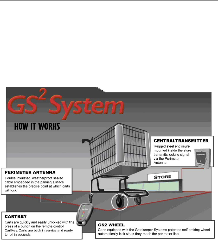
GS2 System
The GS2 System is a perimeter-based, electronic
system that prevents the removal of carts from the
store premises. The GS2 System combines a
digitally-encoded locking signal, embedded
perimeter antenna, and our patented self-braking
cart wheel to provide the most advanced, effective,
and easy-to-operate cart containment solution
available. The CentralTransmitter transmits a
digitally encoded signal via an antenna that is
embedded in the parking lot. The path of the
antenna establishes a perimeter boundary, which
carts may not pass. When a cart equipped with the
GS2 Wheel comes within approximately one meter
of the perimeter boundary, the locking mechanism
engages, thus disabling the cart from use until store
personnel unlock the wheel using our remote
control CartKey. An effective Site Management
Package, consisting of Parking Lot Signs, Cart
Mounted Signs, and Perimeter Striping, indicate the
presence of the GS2 System for the convenience of
store customers.
Introduction
GATEKEEPER SYSTEMS INC.
2007 CART CONTAINMENT MANUAL
Page 3
GS2 System Components
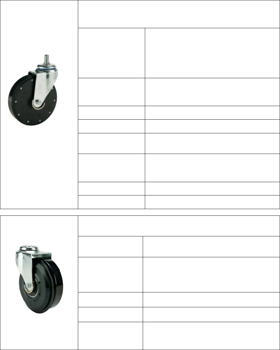
The GS2 Wheel is a completely self-contained unit consisting of a circuit board,
battery, receiver, electric motor, and braking band. The GS2 Wheel comes fully
assembled with its own caster.
Operation The GS2 Wheel contains a digital circuit board, which
receives coded RF signals from in-store transmitters.
The GS2 Wheel translates the coded signal and,
depending on the specific signal received, triggers a
motor inside the wheel to either engage or
disengage the internal braking band.
Form Factor Standard sized cart wheel with a replaceable, non-
marring, conductive (anti-static) tread and sealed
precision ball bearings.
Dimensions 5” diameter x 1.23” width
Power Source One replaceable 3 volt lithium battery, part #CR123A
Electronic
Components
Flash programmable CMOS (low power
consumption) micro-processor.
Electronics
Housing (Hubs)
High tensile strength reinforced plastic with glass
strands for extra strength and durability. Dual o-rings
provide a watertight seal.
Load Rating 180 lbs
GS2 Wheel
Environmental Operating Temperature Range: -10° F to 140° C
The GS2 Travelator contains a side brake for use with moving walkways. The
GS2 Travelator is available in both left and right-side configurations.
Operation The GS2 Travelator utilizes the same leading edge
electronics housed in the GS2 Wheel.
Form Factor Standard-size wheel with replaceable non-marring
anti-static rubber tread, and sealed precision ball
bearings; includes a locking, polyurethane, side-disc
which drops into the grooves of moving walkways
Wheel Dimensions 5” diameter x 1.23” width
Side Disc Dimensions 5.39” diameter x 0.66” width
GS2 Travelator
Track Size Designed for use with the following moving walkways:
track width: approximately 0.11 inch, groove width:
approximately 0.23 inch, groove depth: >39”.
Introduction
GATEKEEPER SYSTEMS INC.
2007 CART CONTAINMENT MANUAL
Page 4
GS2 System Components (cont.)
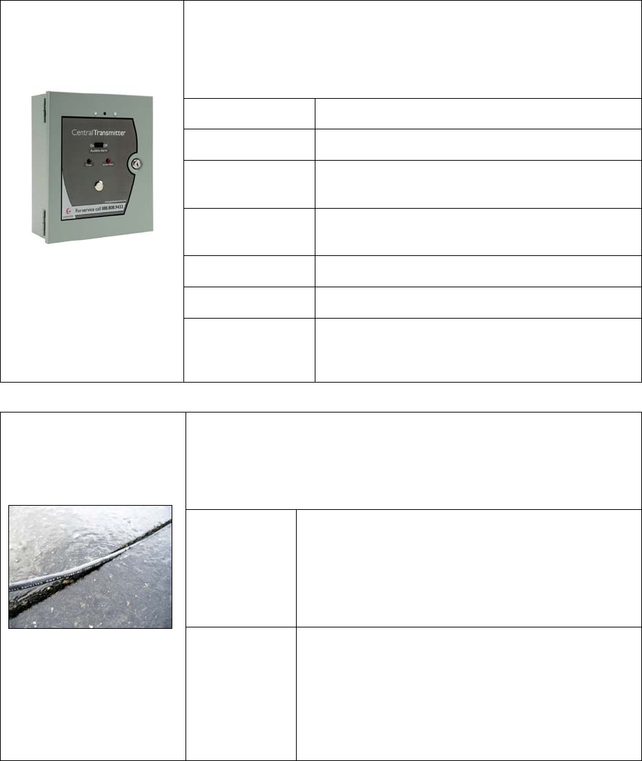
The CentralTransmitter contains a microprocessor that generates and transmits
a digitally encoded locking signal that travels through a cable embedded in the
ground along the designated perimeter. The CentralTransmitter is capable of
generating a locking signal through outdoor perimeter antennas up to 5,000 feet
in length.
Form Factor High-strength steel enclosure protected by key lock.
Dimensions 12.5” high x 10.5” wide x 4.25” deep
Microprocessor Digital circuitry, flash programmable and compliant with
international regulations
Power Supply 110/220 alternating current transformer; ETL/CSA/CE
Certified
Signal Output Below 9 KHz (VLF)
Output Current 1AMP peak-to-peak
Central Transmitter
Alarm Audible and visible system status. Antenna status and
power supply status may be transmitted to any third
party alarm system via terminal block connections.
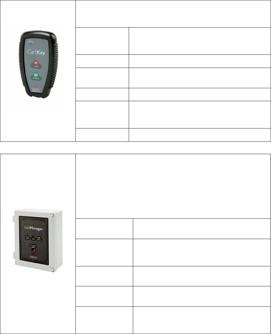
Double-insulated cable embedded that carries the signal from the transmitter
around the designated perimeter and back to the transmitter. Two types of wire
are used in a perimeter antenna installation, single conductor for the locking
signal and twisted pair (neutral) for a null signal. Wire is either embedded
(asphalt, concrete) or routed through EMT conduit, rigid conduit or PVC pipe.
Locking
Signal
14-gauge (AWG), single copper conductor, double-
insulated (PVC/Nylon) wire, (IMSA 51-5). Outer diameter is
0.25”. This is the wire typically used anyplace in outdoor
installation where cart locking is required.
22-gauge (AWG) is primarily used in conjunction with the
ExitManager for indoor installations.
Perimeter Antenna
Null Signal
(twisted pair)
14-gauge (AWG), two copper conductors, double-insulated
(PVC/Nylon) wire. Outer diameter is 0.25”.
This twisted pair wire is designed to cancel the effects of
the locking signal, thus creating a “non-locking, or “neutral”
signal. Twisted pair is most often used to route the neutral
signal from the CentralTransmitter inside the store to the
outside perimeter locking antenna.
Introduction
GATEKEEPER SYSTEMS INC.
2007 CART CONTAINMENT MANUAL
Page 5
GS2 System Components (cont.)
Handheld wireless device used to either unlock or lock GS2 Wheels. The
CartKey sends a digital signal to the GS2 Wheel that automatically unlocks or
locks the wheel
Form Factor Water-tight, high-strength plastic with shock-resistant
rubber boot; touch pad features two individual sealed
dome switches labeled “Lock” and “Unlock”
Dimensions 6.22” high x 3.50” wide x 1.22” deep
Power Source Field-serviceable CR123A, 3-volt, lithium battery identical
to the one installed in the GS2 Wheel
Signal Output Below 9KHz (VLF)
Signal Range 4 feet maximum range; optimal signal range: 1.5 feet – 4
feet; wireless signal range enables point-and-click
unlocking
CartKey
Output Current 138 mA
The ExitManager contains a microprocessor that generates and transmits a
digitally encoded signal through a closed perimeter cable loop (generally
embedded in asphalt or concrete) up to 800 feet in length.
ExitManager is capable of transmitting a single locking signal or generating a
locking signal for one lock box and an unlock signal for a separate lock box.
ExitManager is most commonly used to transmit a locking signal for an indoor or
enclosed perimeter antenna, or to generate a signal for a series of two antennas
in a lock/unlock configuration.
Microprocessor Digital circuitry, factory-programmed and compliant with
FCC Part 15
Power Supply Utilizes 20 volt Uniform Laboratories (U.L.) approved
Alternating Current (A.C.) transformer drawing less than
11 watts. Operates at 115/230V.
Battery Backup 12V non-memory Ni-Cd battery backup array supplies 7
hours of uninterrupted backup.
Signal Output The signal frequency is below 9 KHZ and complies with
FCC Part 15.
ExitManager
Surge Protection The system contains a built-in Surge Protector, which
helps eliminate Electrostatic Discharge from power lines
and lightning strikes.
Introduction
GATEKEEPER SYSTEMS INC.
2007 CART CONTAINMENT MANUAL
Page 6
Instructions to the User for FCC
Each component of the GS2 system complies with Part 15 of the FCC Rules. Operation is subject to the following
two conditions: (1) This device may not cause harmful interference, and (2) This device must accept any interference
received, including interference that may cause undesired operation.
This equipment has been tested and found to comply with the limits for a Class B digital device, pursuant to part 15
of the FCC Rules. These limits are designed to provide a reasonable protection against harmful interference in a
residential installation. This equipment generates, uses, and can radiate radio frequency energy and if not installed
and used in accordance with the instructions, may cause harmful interference to radio communications. However,
there is no guarantee that interference will not occur in a particular installation. If this equipment does cause
harmful interference to radio or television reception, which can be determined by turning the equipment off and on,
the user is encouraged to try to correct the interference by one or more of the following measures:
Reorient or relocate the receiving antenna.
Increase the separation between the equipment and receiver.
Connect the equipment into an outlet or a circuit different from that to which the receiver is connected.
Consult the dealer or an experienced radio/TV technician for help.
Any changes or modifications not expressly approved by the party responsible for compliance could void user’s
authority to operate the equipment.
Information for Canadian Users (IC Notice)
Operation is subject to the following two conditions: (1) This device may not cause interference, and (2) this device
must accept any interference, including interference that may cause undesired operation of the device.
.

Pre-Installation Tasks
GATEKEEPER SYSTEMS INC.
2007 CART CONTAINMENT MANUAL
Page 7
3 Pre-Installation Tasks
The Site Survey
The site survey is perhaps the single most important step in the entire installation process. The purpose of the
survey is to collect detailed information about the area where the GS2 System will be installed. This information
includes exact measurements of the site, photographs from numerous angles, notes on possible obstacles,
location of existing exits, walkways and landscaping, and a host of other data.
A meticulously executed site survey can save hours or even days of work later on during the installation process.
Pre-Planning
Prior to visiting the store, it is important to gather as much store-specific information as possible. If you are
provided a site plan prior to your store visit, it is helpful to review the site plan in an effort to identify potential
installation obstacles. Even for the most difficult of store layouts, with careful planning and execution, the correct
antenna path will be achieved.
Some important questions to consider beforehand include:
• What is the basic store location and layout?
• What are the store’s expectations as far as where they want their customers to be able to take carts?
• Is the store a freestanding structure or it is attached to other businesses? Does the store wish to allow
their customers to take carts to adjacent retailers?
• Is the store located in a multi-level structure? Is there a multi-level car park attached to the store?
• Are there any issues regarding construction, such as local noise ordinances that will prohibit saw cutting
during certain hours?
• Is the store currently under construction or is any construction planned for the near future?
Tools and Materials Needed for the Site Survey:
• Digital Camera,
• Distance Measuring Wheel (available at most hardware stores),
• Measuring Tape,
• 1/4" grid notepad and clipboard,
• Gatekeeper Site Survey Checklist (attached).
Arriving at the Site
Upon arrival at the site, make certain to enter the store and introduce yourself to the store manager on duty. Tell
them why you are there and what you will be doing. Ask permission to enter areas of the store not normally
accessible to the public. Also, notify them that you will be taking pictures of some of the store areas for purposes
of planning the implementation. If you are visiting a store that is not yet open to the public, attempt to identify and
notify the general contractor of your presence and purpose.
Assessing Store Operational Patterns
If possible, discuss the particulars of store operation with the store manager or other store personnel. It is also
helpful to take time to observe the general customer traffic patterns (it helps to do this at a time when the store is
operating at or near capacity.) Where do the customers typically take their carts? This will ensure that your
antenna path is designed in a manner not to interrupt typical customer traffic patterns. Some things to note
include:
• To which areas of the car park should customers be able to take carts?
Pre-Installation Tasks
GATEKEEPER SYSTEMS INC.
2007 CART CONTAINMENT MANUAL
Page 8
• Where do most of the store customers park? Are there any spaces outside the store’s parking domain
where customers might reasonably be expected to take carts? Are there any associated or integrated
businesses such as a gas station to which customers will need to have access?
• Location(s) of cart storage areas. Are the carts kept in cart corrals? Where are the cart corrals located?
This is important because you do not want to route the system antenna within six (6) feet of any location
where carts are stored permanently.
Assessing the Parking Lot Layout and Surrounding Property
While you are at the store, make sure to walk the entire site, including behind the store. Some important
information to note during this process includes:
Does store practice allow the use of carts to move items about in the receiving dock area? If it does, you will
want to ensure that the perimeter antenna encompasses the receiving area.
Are there any barriers on any sides of the perimeter? Are these barriers permanent and high enough that a cart
cannot be lifted over it?
A low hedge (less than four feet high) or landscaping should not be considered a permanent barrier. Over time,
walkways may develop through the hedge, allowing a path for carts to escape if the area is not secured by a
locking perimeter antenna.
Determining the CentralTransmitter Location
The location of the Central Transmitter is critical. It is important to find a secure, ventilated area protected from
any possible damage or tampering. The CentralTransmitter should be mounted on the interior surface of an
exterior wall in the receiving or customer service areas. Power availability should also be considered when
choosing a location. The CentralTransmitter operates on 110 volts AC and should always be connected to a 24-
hour power source. It is best to mount the transmitter in a location that will allow the antenna cable to exit the
store as close as possible to the location of the CentralTransmitter. It is never advisable to place the transmitter
in a location that would require the antenna to travel any significant distance within the store itself. It is often
necessary to route the antenna from the CentralTransmitter, down to ground level within the store, and then drill
through the base of the exterior wall directly into the ground.
In determining the location for the CentralTransmitter, it is important to bear in mind the possibility of any other
conductive surfaces that may cause coupling. Coupling is a condition in which the GS2 signal generated from the
CentralTransmitter is carried by another conductive structure, such as rebar in concrete, metal store fronts, metal
drain pipes, or electrical/data lines. Essentially, the signal carried from the transmitter by Gatekeeper’s antenna
“jumps” to another conductive structure. At this point, the signal is carried by the new structure. If a GS2 Wheel
comes within range of this structure, it is possible that it will receive the GS2 signal and initiate the locking
process. Proper transmitter placement combined with careful antenna routing can effectively eliminate the
possibility of coupling taking place. Always avoid routing the antenna inside the front of the store or near any in-
store data cable routes.
While the store manager may express a preference regarding the location of the transmitter, it is important to
discourage any placement that may result in less-than-optimal system performance. Be prepared to explain why
a specific transmitter location would be undesirable.
Determining System Component Requirements
Once you have acquired information regarding the store’s cart containment requirements, you can go about
determining what components that will be required to deliver a system that meets customer requirements. It is
important to understand what system components are available and the capabilities and limitations of the
different components, especially when planning a more complex layout. For a detailed description of available
components, see the “Error! Reference source not found.” section on page 2.
Pre-Installation Tasks
GATEKEEPER SYSTEMS INC.
2007 CART CONTAINMENT MANUAL
Page 9
Perimeter Antenna Configurations
Using the information from the Site Survey, you can now determine the optimal Perimeter Antenna configuration.
The four primary perimeter antenna configurations are described below. Use as is or tailor to your particular site
needs.
1. Single Locking Loop
A single locking loop is the most effective method of containing carts in a free-standing store environment.
This configuration is utilized when it is possible to run the antenna out from the transmitter (in combination
with using twisted pair to get out of the building), all the way around the intended perimeter, and back to the
transmitter. When laying out a system using a single loop, it is important to confirm that there is room behind
the store or other buildings to saw cut the antenna path. If the store abuts another property or building, it
may not be possible to work behind the building (see sample Site Plans).
2. Double Saw Cut Locking Loop
Often in sites where the store is attached to other buildings, it is not possible to route the antenna around or
over the attached buildings and back to the CentralTransmitter. Remember, a single locking line needs to
complete a loop back to the CentralTransmitter. In these instances, you may choose to route the antenna in
a double saw cut configuration. In this layout, twisted pair leaves the CentralTransmitter and is then
connected to a long single loop that runs around the perimeter locking area and then back along in a parallel
path, with at least two (2) feet of separation. By routing it back along the same path, you have enabled a
closed loop configuration (see “Sample Site Plans”).
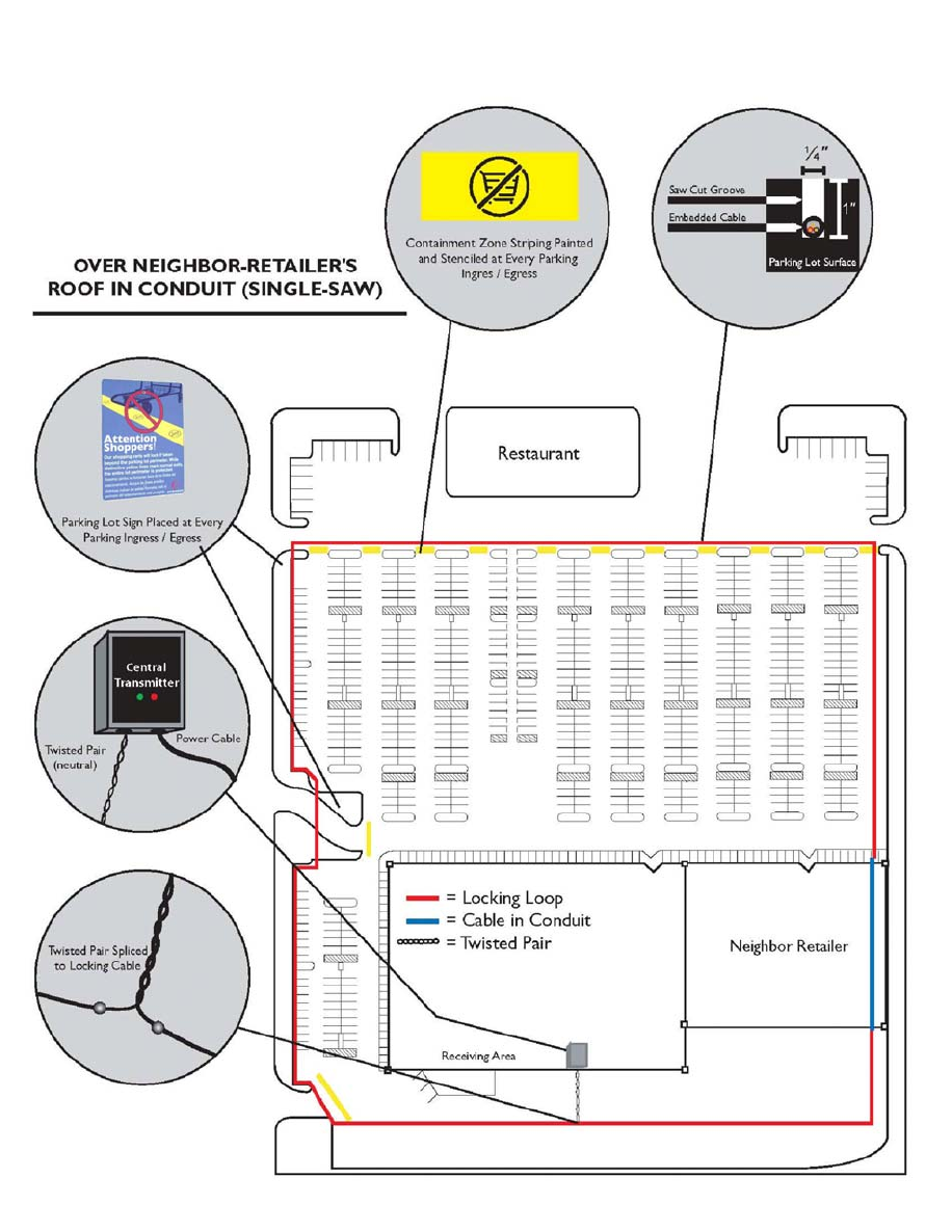
3. Single Locking Loop Over Building
An alternative to the double saw cut for instances where the store is connected to other buildings, is to route
the antenna around the store in a single loop, and up and over the roofline of the connecting buildings. This
installation type allows for a single saw cut in the parking lot area and is often the most efficient way to
design the system. It is important to note a few things when considering this layout: Is there an easy way to
route the antenna up the side or front of the connected building in conduit? Are there any awnings on the
connected buildings that will make this task difficult? Keep in mind at all times that you should NEVER
penetrate any roof or permanently attach anything to the roof.
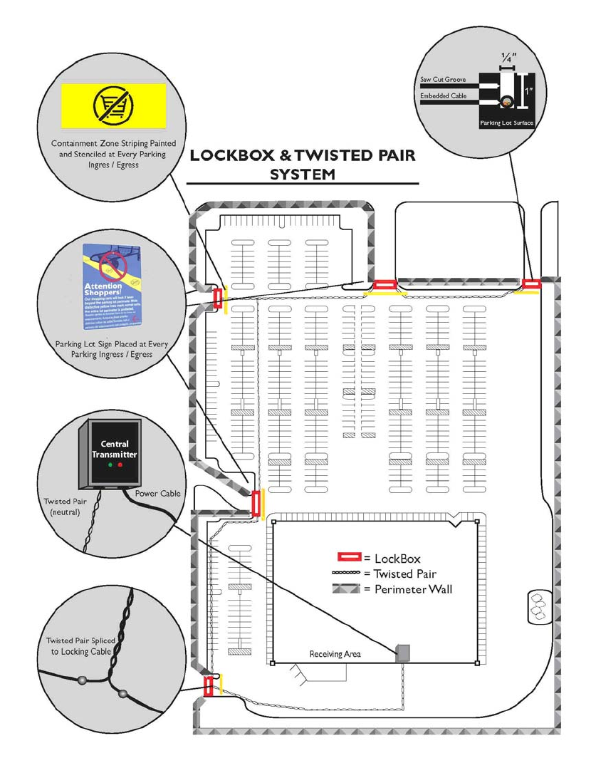
4. Twisted Pair and Lockbox Combination
If a site’s perimeter contains many existing barriers, it is often best to configure the system using a twisted
pair and lockbox combination. This will minimize the total size of the installation and provide an effective cart
containment perimeter. This is generally designed with twisted pair leading from the CentralTransmitter out
to the areas that do not have an existing perimeter boundary, such as a fence or wall. When the antenna
reaches this area, the twisted pair is then spliced to a lock box of single conductor locking line. A lock box is
a rectangular box created by embedding 14g locking loop in a rectangular, box formation, with at least 24
inches separation between the long sides of the rectangle (see “Sample Site Plans”).
Pre-Installation Tasks
GATEKEEPER SYSTEMS INC.
2007 CART CONTAINMENT MANUAL
Page 10
Other Perimeter Antenna Considerations
Antenna on Slopes
Similar caution should be exercised when routing the antenna across any area that slopes downhill. If the
antenna path is routed across a sloped area, it should always be routed along the top portion of the slope. When
routing the antenna across rows of parking spaces, it is important to always place the antenna at the end of the
parking space (where the nose of the car would be located). As the GS2 locking signal will be transmitted
approximately three feet from the antenna path, the cart will actually begin locking at the middle portion of a
parked car, if the antenna is placed at the nose end of the parking space. Were the antenna to be routed across
the entry to the parking space, a shopper would not be able to push the cart to their car, as it would begin to lock.
This is both an inconvenience to the shopper, as well as to the store.
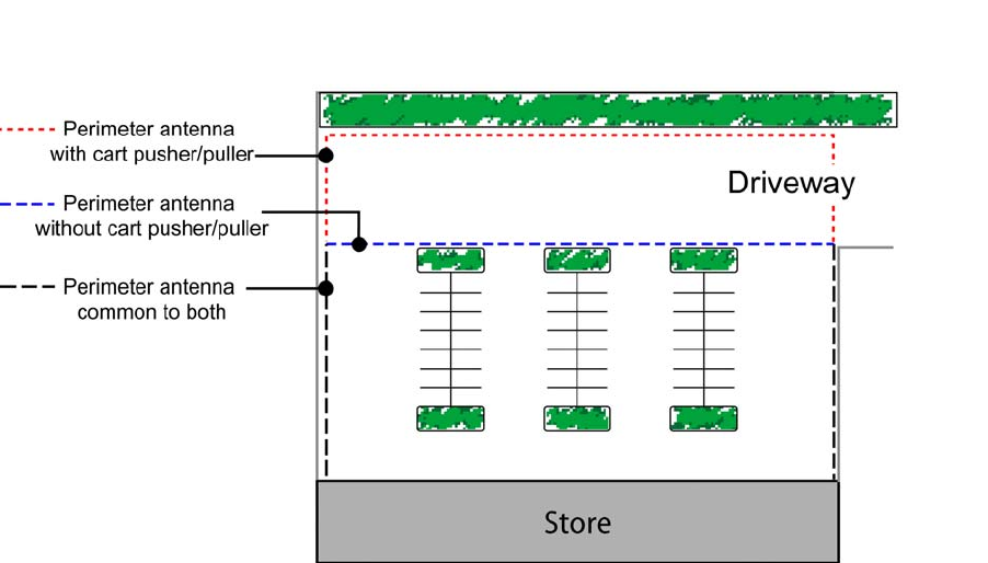
Antenna Across Driveways
The placement of the perimeter antenna when crossing driveways will vary depending on whether or not the
store is using a cart collection system. The two options are shown in the diagram below.
Pre-Installation Tasks
GATEKEEPER SYSTEMS INC.
2007 CART CONTAINMENT MANUAL
Page 11
Documenting the Site Survey
When you visit the site, it is important to take notes for future reference. The “Site Survey Checklist” on page 17,
contains most of the information that is needed to prepare a final Scope of Work and should be completed in its
entirety with every site survey.
In addition to the checklist, you will need to either mark-up an existing store site plan (provided by Gatekeeper)
or create one from scratch using your grid paper and measuring wheel. It is important to include measurements
of the entire perimeter on your drawing, including the segmented measurements on each side of the perimeter. If
the installation requires conduit on a wall or over a roof, indicate the approximate height of the structures on your
drawing.
Drawing the Site Diagram
When drawing your site diagram, attempt to include relevant detail about the property, including:
• Basic overview of parking lot and structures
• Store dimensions
• Sidewalks, walkways, etc.
• Store entry and exit points
• Cart corrals
• Indicate parking lot surfaces, e.g. asphalt, concrete etc.
• Condition of the parking lot surface
• Permanent fencing or walls that create boundaries. Low (4 feet or less) hedges are NOT considered
permanent barriers.
• Additional businesses in the parking lot area (attached or unattached)
• Landscaped areas within the proposed antenna path (including trees)
• Main points of ingress/egress from the parking lot
• Vehicle traffic lanes within the parking lot
• Use different color pens to indicate the different types of antenna, for example: red = locking line; green
= twisted pair; blue = conduit; orange = landscaping
• When attaching digital photos, label the image files in sequential order beginning with one and use
those numbers to indicate specific locations on your site diagram
Before marking up an official architectural print (or copy thereof), be certain to make a duplicate of the original
print.
Finally, it is important to take as many photographs as possible. The photographs are a vital means of
communicating the final site plan and antenna path layout to our mutual customer. Photographs should be taken
at multiple locations throughout the site. Each photograph should be numbered. Always indicate on the site plan
the exact spot where the photograph was taken and the direction the photographer was facing, as shown on
page 12.
Pre-Installation Tasks
GATEKEEPER SYSTEMS INC.
2007 CART CONTAINMENT MANUAL
Page 12
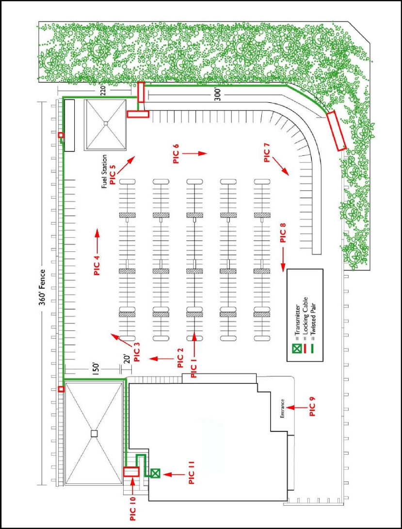
Sample Photograph Map
The entries on this map (PIC1, PIC2…) indicate the locations where pictures were taken. Arrows show the
direction the photographer was facing. Numbers on the site plan should match the number on the back of the
corresponding photo.
Pre-Installation Tasks
GATEKEEPER SYSTEMS INC.
2007 CART CONTAINMENT MANUAL
Page 13
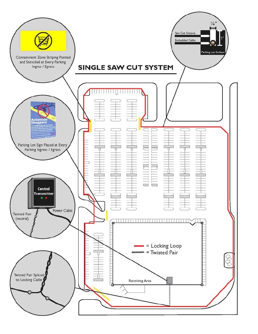
Sample Site Plans
Single Locking Loop
This plan shows a single perimeter antenna leaving the CentralTransmitter via a short run of twisted pair, circling
the containment area and returning to the CT. This is usually the simplest, most efficient setup.
Pre-Installation Tasks
GATEKEEPER SYSTEMS INC.
2007 CART CONTAINMENT MANUAL
Page 14
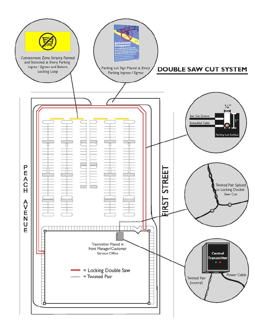
Double Saw Cut
A double saw cut system is used when a single continuous loop is not possible, usually because the area at the
back of the building is not accessible for antenna installation. This method is more work intensive, but avoids
conduit running over the top of the building.
Pre-Installation Tasks
GATEKEEPER SYSTEMS INC.
2007 CART CONTAINMENT MANUAL
Page 15
Twisted Pair And Multiple Lockboxes
Use this configuration when large parts of the containment perimeter are defined by impassable landscaping,
walls, other buildings, etc. Twisted pair is used to connect a series of “lockboxes”, which are small perimeter
antenna loops across areas of ingress/egress to the site.
Pre-Installation Tasks
GATEKEEPER SYSTEMS INC.
2007 CART CONTAINMENT MANUAL
Page 16
Single Locking Loop - Over Roof
Installation of antenna in conduit over a roof can be used when an otherwise simple single perimeter line is
interrupted by an attached or neighboring building.
Pre-Installation Tasks
GATEKEEPER SYSTEMS INC.
2007 CART CONTAINMENT MANUAL
Page 17
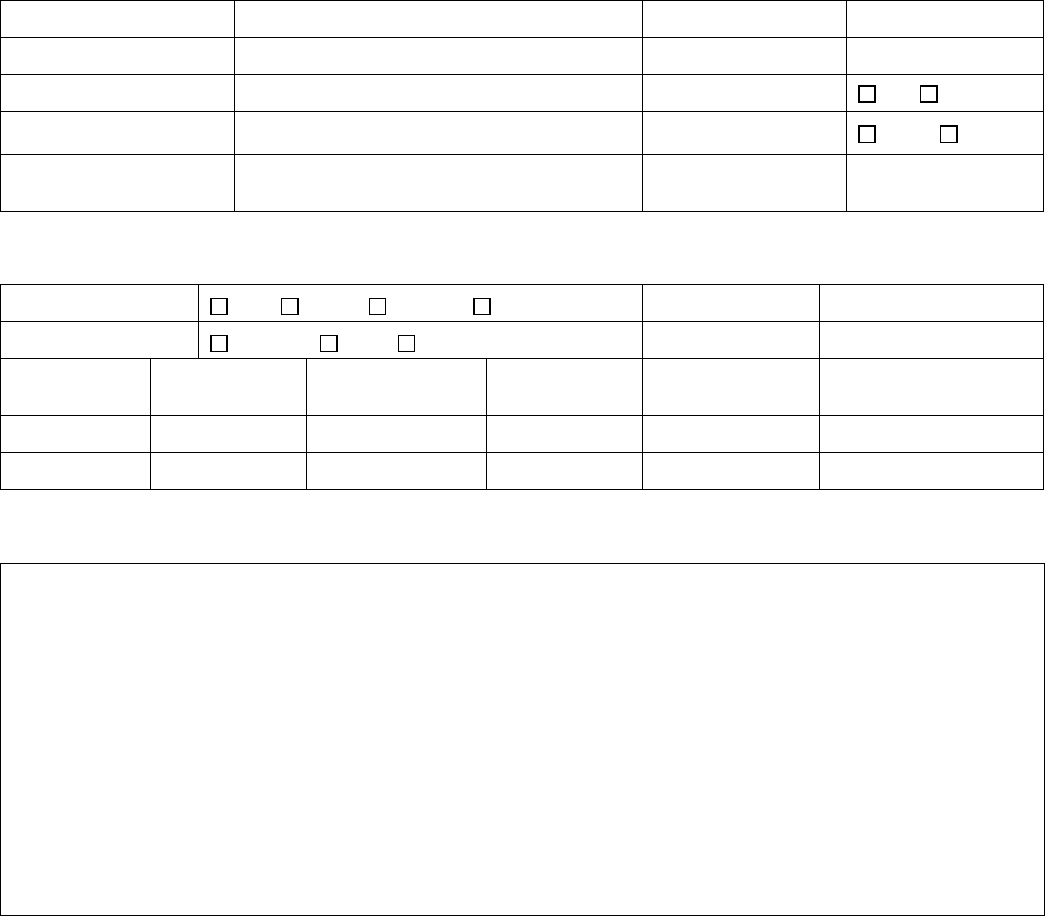
Site Survey Checklist
SITE INFORMATION
Store Name / No: Survey Date:
Street Address: Survey Taker:
City / State / Zip Code : New Construction: Yes No
Store Phone: Parking Lot: Paved Dirt
Store Director: Est. Completion Date
of Construction:
SYSTEM CONFIGURATION
Antenna Layout: Loop Double Lock Box Over Roof Asphalt Footage:
Transmitter: Receiving Office Front of Store Concrete Footage:
# of Signs: # of Sign Posts:
Landscape
Footage:
Locking Line: Twisted Pair: Conduit: Footage
# of Stripes: Avg. Stripe LF: Total Antenna LF:
SITE COMMENTS
A site plan indicating the antenna layout, with locking line and twisted pair clearly identified, transmitter location,
key site measurements, sign locations, sign posts required, and striping locations must accompany this site
survey.

Installation
GATEKEEPER SYSTEMS INC.
2007 CART CONTAINMENT MANUAL
Page 18
4 Installation
Overview
Installation of the GS2 System will require two to three field service technicians and may take up to four days,
depending on the size of the installation, site availability and weather.
It is recommended that work begin as early in the day as possible, while customer activity is light and the parking
lot is fairly empty. Prior to the day of installation, you will need to verify with your site contact when you can begin
your work.
This chapter contains the following sections:
• Required tools and materials
• Arriving on site
• Confirming the CentralTransmitter location
• Marking the antenna path
• Saw cutting the marked area
• Removing saw cut residue
• Installing the perimeter antenna
• Splicing the antenna
• Sealing the saw cut
• Mounting the CentralTransmitter
• CentralTransmitter front panel
• CentralTransmitter main circuit board
• Connecting electrical power to the CentralTransmitter
• Calibrating the CentralTransmitter
• Selecting the transmitter mode
• Connecting the alarm relays
• Information tracker
• Perimeter striping
• Installing the parking lot signs
• Installing the tilt bars
• Installing the GS2 wheel
• Installing the cart mounted signs

Installation
GATEKEEPER SYSTEMS INC.
2007 CART CONTAINMENT MANUAL
Page 19
Required Tools and Materials
The following table lists the tools and materials that are required for a standard GS2 installation. You may need
additional items, depending on the specific needs of your installation.
Item Task / Purpose
Truck or van capable of transporting a self
propelled concrete saw.
Moving material and equipment to installation site.
Measuring wheel Measure the total footage of the Perimeter Antenna
Caution tape Blocking off the work area
Traffic cones Blocking off the work area
Chalk line/string and paint Indicating antenna path for saw cutter
Self propelled concrete saw Installing antenna
¼” saw blade Cutting asphalt and/or concrete
Concrete/asphalt hand saw Cutting asphalt and/or concrete
Hilti saw w/ roller plate attachment Cutting indoor loops
4 ½” angle grinder Fine saw cuts at corners or bends
Electric or cordless impact wrench Installing GS2 Wheel
Wet/Dry vacuum Cleaning out a wet saw cut
Power sweeper Cleaning up debris from a dry saw cut
Wire caddy or dispenser Rolling out Perimeter Antenna wire
Gatekeeper cleaning hook Cleaning out the saw cut
Gatekeeper antenna roller Rolling the antenna into the saw cut
Drill with roto-hammer option Curb and wall penetrations
Assorted drill bits Standard and mason bits
Conduit bender ½” EMT conduit
Fish tape Pulling antenna through conduit
Pour pot (Type 1 or 2) Applying asphalt sealer
V-squeegee Removing excess sealer
1 large and 1 small caulking gun Sealing concrete areas
6’ step ladder Installing CentralTransmitter and Parking Lot Signs
Extension ladder Conduit risers and roof work
Electrical generator (1850 watt minimum) Supply A/C to hand tools
Portable propane soldering torch Performing antenna splices
Scotchkote Electrical Coating Coat the antenna splices before the shrink tube
Shrink tubing Performing antenna splices
Electrical multi-meter Measuring resistance within the Perimeter Antenna
Wire cutters/strippers Antenna splices and terminations
Shovels, different sizes Installing antenna into garden areas
Pick Installing antenna into garden areas

Installation
GATEKEEPER SYSTEMS INC.
2007 CART CONTAINMENT MANUAL
Page 20
Item Task / Purpose
9” paint roller with ¾” NAP Painting Perimeter Striping
Respirator (2 pair) Safety equipment for saw cutting
Safety glasses (2 pair) Safety equipment for saw-cutting and drilling
Ear protection (2 pair) Safety equipment for saw cutting
Kleen Sweep 27 Push sweeper for cleaning up saw cut residue
Approved providers: Minuteman International
Leaf blower Cleaning fine dust from saw-cut after a dry cut
14 AWG single conductor antenna Locking loop antenna
Approved providers: Beldin, Coleman
14 AWG two conductor antenna Twisted pair antenna (null signal)
Approved providers: Beldin
½” rigid conduit Antenna runs up buildings
½” EMT conduit Antenna runs up buildings
Conduit straps Antenna runs up buildings
Conduit LBs Antenna runs up buildings
Concrete sealer Self leveling concrete sealant
Approved providers: QuikRete, SikaFlex
Asphalt sealer Cold pour asphalt sealant
Approved providers: Craftco (Tri-American), SealMaster
Traffic Paint Perimeter striping
Approved providers: Gliden Ultra-Hide Durus Acrylic Traffic Paint
(Lot# GL-0087)
Installation
GATEKEEPER SYSTEMS INC.
2007 CART CONTAINMENT MANUAL
Page 21
Arriving On Site
Telephone the store management (if the store is operational) or construction site supervisor (for a store still
under construction) several days before the installation and inform them of your planned installation dates, start
time, and scope of work. If possible, get the name of a specific person to contact when you get to the site. On
arrival, check in with your contact person. Introduce yourself and be sure that they understand the scope of the
planned work, when you want to begin, and about how long you expect to be on site. Be open to suggestions on
how to minimize impact to store operations or construction schedules.
Confirming the CentralTransmitter Location
Confirm the location of the CentralTransmitter as indicated on your site plan. Verity that you have access to a
110 volt AC power supply (outlet or hardwired) and determine the location and accessibility of the circuit breaker
that energizes the line.
Determine how you will route the perimeter antenna from the CT to the outside of the building. Ideally, the
antenna should be enclosed in rigid conduit from the CentralTransmitter, down the inner wall of the store to the
floor. A hole is drilled in the wall and the conduit is routed through to the base of the exterior wall.
If ground level penetration from the inside of the store is not possible, than you should penetrate the building wall
from the interior, at the height of the CentralTransmitter, and route the antenna down the exterior wall in rigid
conduit. For more information on running antenna through conduit, see page 23.
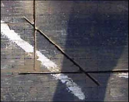
Marking the Antenna Path
Use a chalk line or spray paint to mark the path of the
saw cut prior to cutting. Mark your lines exactly as you
want the cut to be performed. This will help the saw cutter
in making a straight saw cut. Make 45º angles through
any 90º turns. You should NEVER make a 90º bend with
the antenna, as it may cause the locking signal to be
transmitted in a sporadic pattern at the 90º bend. It is
helpful to mark off all areas requiring saw cutting with
yellow caution tape or traffic cones. If you are beginning
early in the morning, you might consider instructing one
member of the installation team to begin striping the
parking lot at this time. The most convenient time to stripe
the lot is at the beginning of the day, before cars have
begun to enter the parking lot. This will require a
minimum crew of two technicians: one saw cutter and one
to begin the perimeter striping.