GatesAir CZF Ranger CZ725F User Manual Printing File 8435560108 PLT
GatesAir, Inc. Ranger CZ725F Printing File 8435560108 PLT
GatesAir >
Contents
- 1. Users Manual D0
- 2. Users Manual D1
- 3. Users Manual D1A
- 4. Users Manual D2
- 5. Users Manual E
Users Manual D1A
Rs-232 Communication Protocol Sheet 1 of 10 Rev: C Dwg: 817-2435-971
HARRIS CORPORATION
BROADCAST COMMUNICATIONS
P.O. BOX 4290
QUINCY, IL 62305
THIS DOCUMENT CONTAINS PROPRIETARY DATA
OF HARRIS CORPORATION. NO DISCLOSURE,
REPRODUCTION, OR USE OF ANY PART THEREOF
MAY BE MADE EXCEPT BY WRITTEN PERMISSION.
REVISIONS
Rev: Date: Dftm: Eng: ECN Number: Rev: Date: Dftm: Eng: ECN Number:
C 07/28/03 CLL CLL P22911. B 6/19/03 CLL CLL P22240
CHANGES IN FIELD
APPROVALS
Drawn
By: C. LUCKHAUPT
2003 Eng: C. LUCKHAUPT
2003 Proj: B. KLESNER
2003 Mfg: M THOMPSON
2003
Rs-232 Communication Protocol
For Remote Serial Controller 992-9511-500 with 817-2435-970
software installed
Rev. C

Rs-232 Communication Protocol Sheet 2 of 10 Rev: C Dwg: 817-2435-971
Scope
The purpose of this document is to provide the necessary information to access the REMOTE SERIAL
CONTROLLER (9929511500) with basic Rs-232 software installed (8172435970)
Table of Contents
I. Request Packet Format................................................................................................................... 3
II. Response Packet Format ................................................................................................................ 3
III. Packets ............................................................................................................................................ 8
I. Request Packet................................................................................................................... 8
II. Response Packet................................................................................................................ 8
III. Reset Packet....................................................................................................................... 8
IV. CMD.................................................................................................................................... 9
V. Ports.................................................................................................................................... 9
Table of Figures
Table 1 Board Address ................................................................................................................................4
Table 2 Baud Rate .......................................................................................................................................4
Table 3 Packet ID’s......................................................................................................................................5

Rs-232 Communication Protocol Sheet 3 of 10 Rev: C Dwg: 817-2435-971
I. Request Packet Format
Data transmission rate is selectable from 115200,57600,19200,9600 bps. Communication format is 8
data bits, no parity bits, and one stop bit. The data packet structure is defined below. Note that the
’Packet ID’ byte uniquely identifies each packet. The CRC value is used to verify that valid data has been
received.
Packet Structure:
Byte 01: Header Byte 1 ASCII code "H” or 72
Byte 02: Header Byte 2 ASCII code "B” or 66
Byte 03: Packet Address Value: 0–63, based on Switch 1 on Board. (See Table 1)
Byte 04: Packet ID Value 0-32 (See Table 2)
Byte 05-XX: Data bytes
Byte XX + 1: 16 bit CRC, MSB
Byte XX + 2: 16 bit CRC, LSB
Notes:
Header Bytes are not included in CRC Calculation.
II. Response Packet Format
Data transmission rate is selectable from 115200,57600,19200,9600 bps via S1 (7-8). Communication
format is 8 data bits, no parity bits, and one stop bit. The data packet structure is defined below. The
CRC value is used to verify that valid data has been received.
Packet Structure:
Byte 01: Header Byte 1 ASCII code "H" or 72
Byte 02: Header Byte 2 ASCII code "B" or 66
Byte 03: Packet Address 255 (Always 255)
Byte 04-XX: Data bytes
Byte XX + 1: 16 bit CRC, MSB
Byte XX + 2: 16 bit CRC, LSB
Notes:
Header Bytes are not included in CRC Calculation.
Rs-232 Communication Protocol Sheet 4 of 10 Rev: C Dwg: 817-2435-971
Remote Serial I/O Board Switch 1 Configuration
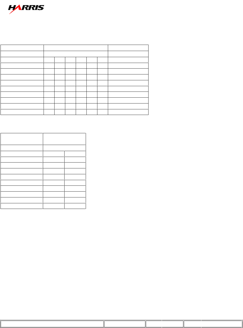
Table 1 Board Address
Packet Address
(Dec Value) Switch 1 #
#6 #5 #4 #3 #2 #1
0 0 0 0 0 0 0
1 0 0 0 0 0 1
2 0 0 0 0 1 0
3 0 0 0 0 1 1
4 0 0 0 1 0 0
5 0 0 0 1 0 1
* * * * * * *
* * * * * * *
63 1 1 1 1 1 1
Table 2 Baud Rate
1= On
0 = Off
Baud Rate Switch 1 #
#8 #7
9600 0 0
19200 0 1
57600 1 0
115200 1 1
Note The Packet Address must be different for each Board
Rs-232 Communication Protocol Sheet 5 of 10 Rev: C Dwg: 817-2435-971
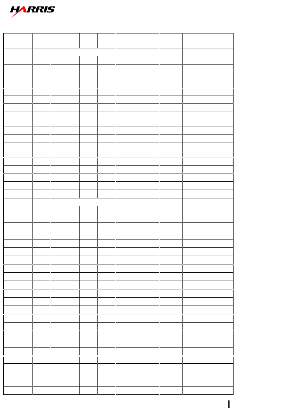
Table 3 Packet ID’s
ID (HEX) Description Data
Bytes Response Packet
0x00 Read Data at J1 & J2 [15:0] //J1 1-8 & J2 1-8
None
2 bytes
J# Bit Value
J1-1 8
J1-2 9
J1-3 10
J1-4 11
J1-5 12
J1-6 13
J1-7 14
J1-8 15 MSB
J2-1 0 LSB
J2-2 1
J2-3 2
J2-4 3
J2-5 4
J2-6 5
J2-7 6
J2-8 7
0x01 Read Data at J3 & J4 [15:0] //J2 1-8 & J4 1-8
None
2 bytes
J# Bit Value
J3-1 8
J3-2 9
J3-3 10
J3-4 11
J3-5 12
J3-6 13
J3-7 14
J3-8 15 MSB
J4-1 0 LSB
J4-2 1
J4-3 2
J4-4 3
J4-5 4
J4-6 5
J4-7 6
J4-8 7
0x02
None
0x03
None
0x04
None
0x05
None
0x06
None
Rs-232 Communication Protocol Sheet 6 of 10 Rev: C Dwg: 817-2435-971
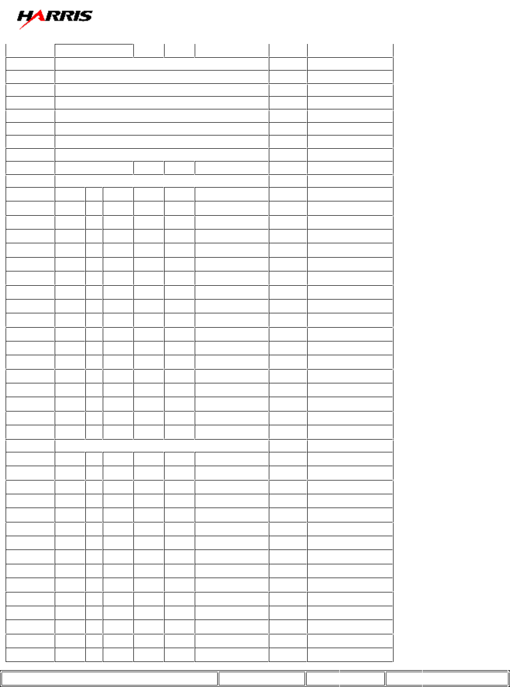
0x07 Status register
None
2 bytes
0x08 Read Analog Data at Channel 0 J5-1
None
2 bytes
0x09 Read Analog Data at Channel 1 J5-2
None
2 bytes
0x0a Read Analog Data at Channel 2 J5-3
None
2 bytes
0x0b Read Analog Data at Channel 3 J5-4
None
2 bytes
0x0c Read Analog Data at Channel 4 J5-5
None
2 bytes
0x0d Read Analog Data at Channel 5 J5-6
None
2 bytes
0x0e Read Analog Data at Channel 6 J5-7
None
2 bytes
0x0f Read Analog Data at Channel 7 J5-8
None
2 bytes
0x10 Write Data at J6 & J7 [15:0] //J6 1-8 & J7 1-
8
2 None
J# Bit Value
J6-1 8
J6-2 9
J6-3 10
J6-4 11
J6-5 12
J6-6 13
J6-7 14
J6-8 15 MSB
J7-1 0 LSB
J7-2 1
J7-3 2
J7-4 3
J7-5 4
J7-6 5
J7-7 6
J7-8 7
0x11 Write Data at J8 & J9[15:0] //J8 1-8 & J9 1-
8
2 None
J# Bit Value
J8-1 8
J8-2 9
J8-3 10
J8-4 11
J8-5 12
J8-6 13
J8-7 14
J8-8 15 MSB
J9-1 0 LSB
J9-2 1
J9-3 2
J9-4 3
J9-5 4
J9-6 5
Rs-232 Communication Protocol Sheet 7 of 10 Rev: C Dwg: 817-2435-971
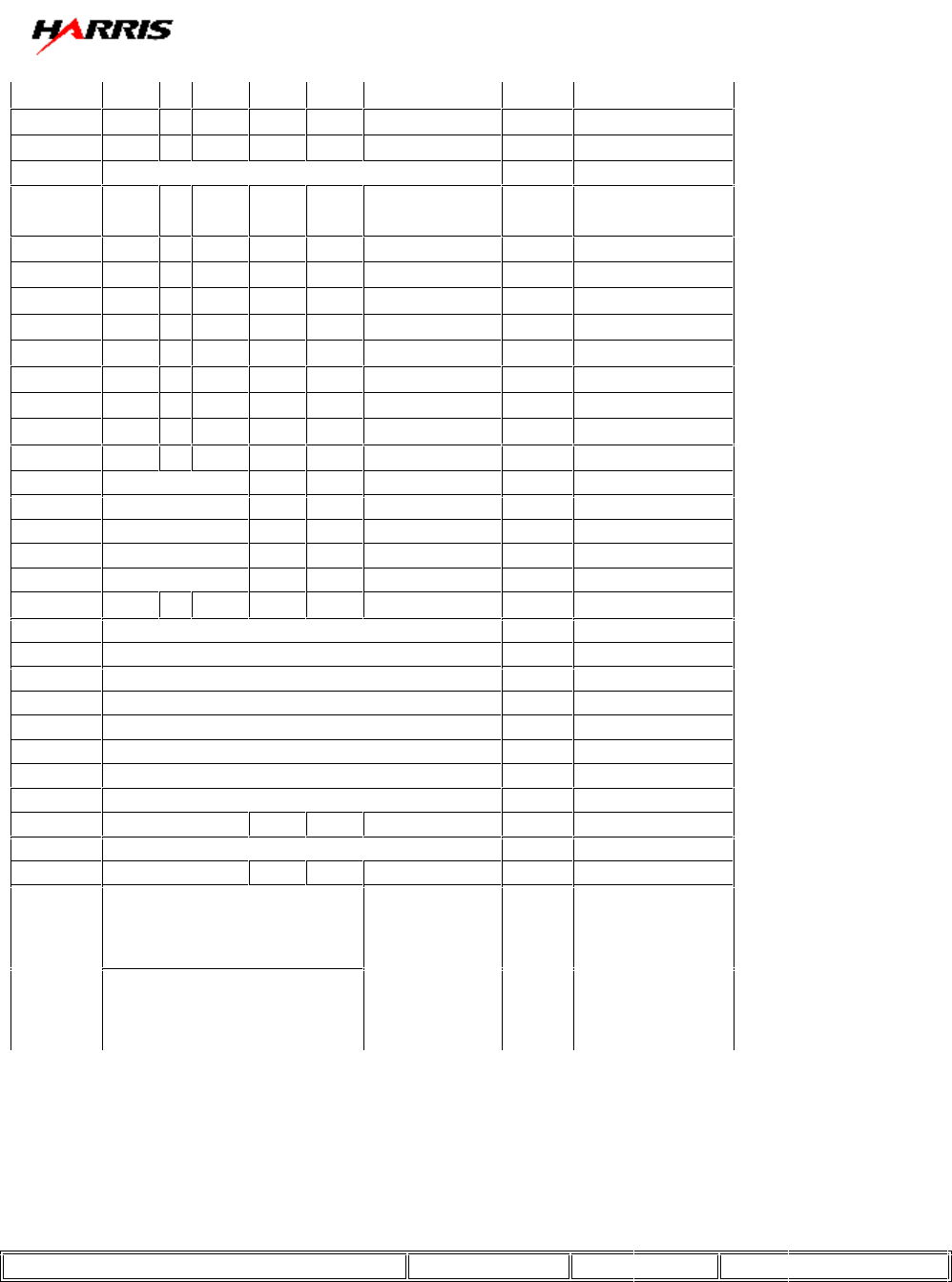
J9-7 6
J9-8 7
0x12 Write Data at J14 [7:0] //J14 1-8 2 None
J# Bit Value
J14-1 0 LSB
J14-2 1
J14-3 2
J14-4 3
J14-5 4
J14-6 5
J14-7 6
J14-8 7 MSB
0x13
None
None
0x14
None
None
0x15
None
None
0x16
None
None
0x17
None
None
0x18 Write Analog Data at Channel 0 J10-1 2 None
0x19 Write Analog Data at Channel 1 J10-2 2 None
0x1a Write Analog Data at Channel 2 J10-3 2 None
0x1b Write Analog Data at Channel 3 J10-4 2 None
0x1c Write Analog Data at Channel 4 J10-5 2 None
0x1d Write Analog Data at Channel 5 J10-6 2 None
0x1e Write Analog Data at Channel 6 J10-7 2 None
0x1f Write Analog Data at Channel 7 J10-8 2 None
0x17 Write Reset Status of FPGA 2 None
0x20 Full Data Dump None 22 bytes (See
Response Packet
Below)
Rs-232 Communication Protocol Sheet 8 of 10 Rev: C Dwg: 817-2435-971
III. Packets
I. Request Packet
72 Packet Byte # 0 Header Byte # 1
66 Packet Byte # 1 Header Byte # 2
1 Packet Byte # 2 Address of “1” selectable by dipswitch on Board
32 Packet Byte # 3 CMD # 2 for Full Data Dump
1 Packet Byte # 4 High CRC
32 Packet Byte # 5 Low CRC
II. Response Packet
72 Packet Byte # 0 Header Byte # 1
66 Packet Byte # 1 Header Byte # 2
255 Packet Byte # 2 Address of 255 (Always on response packet)
255 Packet Byte # 3 Data Byte 0 == I_port_a [8-15] J2 1-8
255 Packet Byte # 4 Data Byte 1 == I_port_a [0-7] J1 1-8
255 Packet Byte # 5 Data Byte 2 == I_port_b [8-15] J4 1-8
255 Packet Byte # 6 Data Byte 3 == I_port_b [0-7] J3 1-8
0 Packet Byte # 7 Data Byte 4 == rev/status register
0 Packet Byte # 8 Data Byte 5 == rev/status register
0 Packet Byte # 9 Data Byte 6 ==Channel 0
0 Packet Byte # 10 Data Byte 7 ==Channel 0
0 Packet Byte # 11 Data Byte 8 == Channel 1
0 Packet Byte # 12 Data Byte 9 == Channel 1
0 Packet Byte # 13 Data Byte 10 == Channel 2
0 Packet Byte # 14 Data Byte 11 == Channel 2
0 Packet Byte # 15 Data Byte 12 == Channel 3
0 Packet Byte # 16 Data Byte 13 == Channel 3
0 Packet Byte # 17 Data Byte 14 == Channel 4
0 Packet Byte # 18 Data Byte 15 == Channel 4
0 Packet Byte # 19 Data Byte 16 == Channel 5
0 Packet Byte # 20 Data Byte 17 == Channel 5
0 Packet Byte # 21 Data Byte 18 == Channel 6
0 Packet Byte # 22 Data Byte 19 == Channel 6
0 Packet Byte # 23 Data Byte 20 == Channel 7
0 Packet Byte # 24 Data Byte 21 == Channel 7
* Packet Byte # 25 High CRC
* Packet Byte # 26 Low CRC
III. Reset Packet
72 Packet Byte # 0 Header Byte # 1
66 Packet Byte # 1 Header Byte # 2
1 Packet Byte # 2 Address of “1” selectable by dipswitch on Board
23 Packet Byte # 3 Reset Status Bit
0 Value Zero Always
0 Value Zero Always
81 Packet Byte # 4 High CRC
231 Packet Byte # 5 Low CRC
This command will ser Bit 0 of Packet Byte #7 Data Byte #5 to 0
Rs-232 Communication Protocol Sheet 9 of 10 Rev: C Dwg: 817-2435-971
Example for Analog Channels
Channel (0) Calculation=(Data Byte [6]*256+ Data Byte [7]); 0 to 255 == 0 to 5v full scale
Packet ID = CMD *16 + Port #
IV. CMD
0= Read Data @ Port # (16 Bits) Total Number of Bytes is 2
1= Write Data @ Port # (16 Bits) Total Number of Bytes is 0 (no return packet)
2= Full Data Dump. Response is 22 bytes:
Analog = 16 bytes (8 channels at 2 bytes each)
Digital = 4 bytes (32 bits)
Rev/Status = 2 Bytes
3=
4=
5=
6=
7=
V. Ports
0= Port A [15:0]
1= Port B [15:0]
2= Port C [7:0] (8-15 unused)
3=
4=
5=
6=
7 = rev/status register:
Rev:
Bits [15-12] = Major revision
Bits [11-8] = Minor revision
(e.g. Rev 4.1 = “0100 0001 0000 0000”)
Status:
Bits [7-1] = unused
Bit [0] = reset status (‘1’ = board was reset, e.g. by power failure)
8-15 (Analog)
8 = Channel 0
9 = Channel 1
10 = Channel 2
11 = Channel 3
12 = Channel 4
13 = Channel 5
14 = Channel 6
15 = Channel 7
Rs-232 Communication Protocol Sheet 10 of 10 Rev: C Dwg: 817-2435-971
Date of
Revision Drawing
Revision
Description of Changes
02/21/03 REV A FIRST RELEASE OF DOCUMENT
06/19/03 REV B MSB and LSB were backwards on table 3
07/28/03 REV C Added Reset Command to Document. Clarified how to calculate the
PACKET ID