GatesAir CZF Ranger CZ725F User Manual Printing File 8435560108 PLT
GatesAir, Inc. Ranger CZ725F Printing File 8435560108 PLT
GatesAir >
Contents
- 1. Users Manual D0
- 2. Users Manual D1
- 3. Users Manual D1A
- 4. Users Manual D2
- 5. Users Manual E
Users Manual D1A
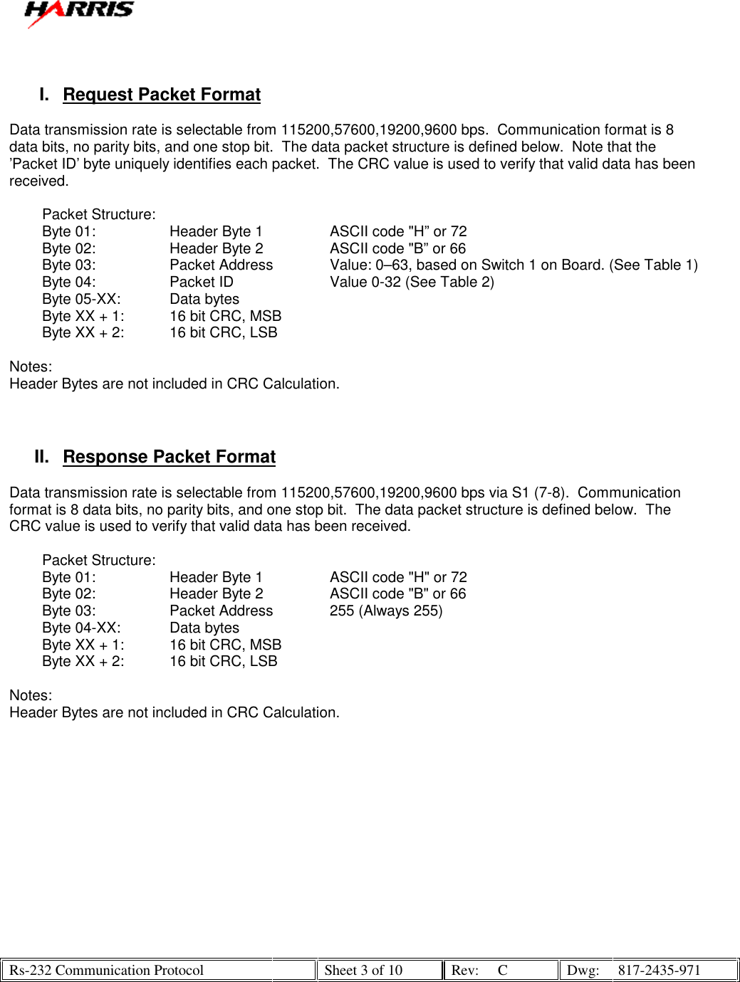
![Rs-232 Communication Protocol Sheet 5 of 10 Rev: C Dwg: 817-2435-971 Table 3 Packet ID’s ID (HEX) Description Data Bytes Response Packet 0x00 Read Data at J1 & J2 [15:0] //J1 1-8 & J2 1-8 None 2 bytes J# Bit Value J1-1 8 J1-2 9 J1-3 10 J1-4 11 J1-5 12 J1-6 13 J1-7 14 J1-8 15 MSB J2-1 0 LSB J2-2 1 J2-3 2 J2-4 3 J2-5 4 J2-6 5 J2-7 6 J2-8 7 0x01 Read Data at J3 & J4 [15:0] //J2 1-8 & J4 1-8 None 2 bytes J# Bit Value J3-1 8 J3-2 9 J3-3 10 J3-4 11 J3-5 12 J3-6 13 J3-7 14 J3-8 15 MSB J4-1 0 LSB J4-2 1 J4-3 2 J4-4 3 J4-5 4 J4-6 5 J4-7 6 J4-8 7 0x02 None 0x03 None 0x04 None 0x05 None 0x06 None](https://usermanual.wiki/GatesAir/CZF.Users-Manual-D1A/User-Guide-939481-Page-6.png)
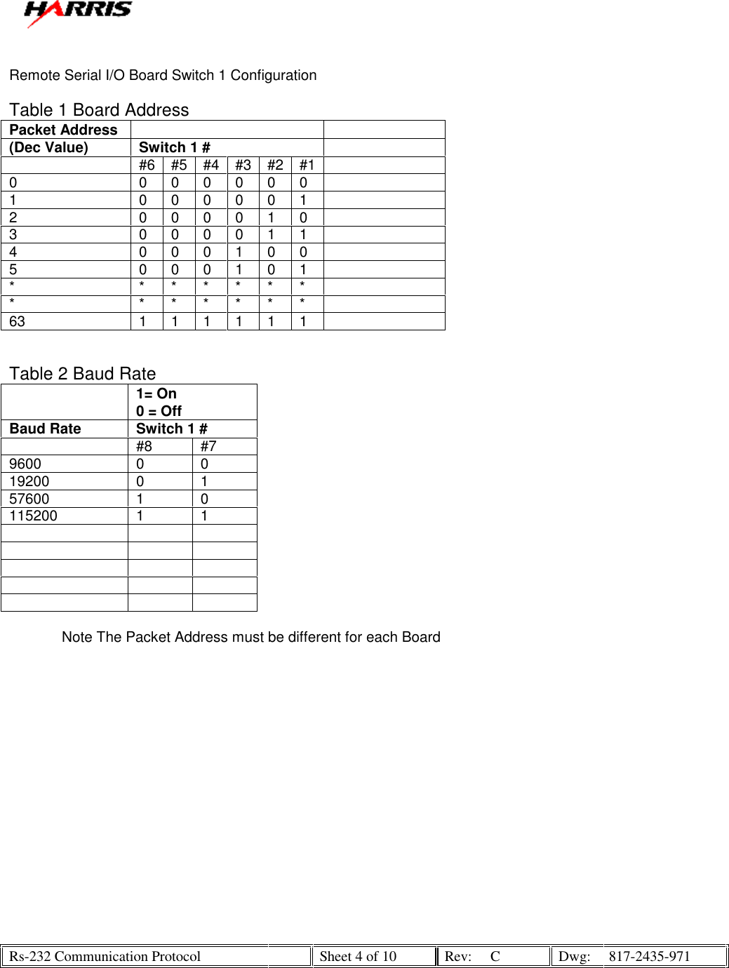
![Rs-232 Communication Protocol Sheet 6 of 10 Rev: C Dwg: 817-2435-971 0x07 Status register None 2 bytes 0x08 Read Analog Data at Channel 0 J5-1 None 2 bytes 0x09 Read Analog Data at Channel 1 J5-2 None 2 bytes 0x0a Read Analog Data at Channel 2 J5-3 None 2 bytes 0x0b Read Analog Data at Channel 3 J5-4 None 2 bytes 0x0c Read Analog Data at Channel 4 J5-5 None 2 bytes 0x0d Read Analog Data at Channel 5 J5-6 None 2 bytes 0x0e Read Analog Data at Channel 6 J5-7 None 2 bytes 0x0f Read Analog Data at Channel 7 J5-8 None 2 bytes 0x10 Write Data at J6 & J7 [15:0] //J6 1-8 & J7 1-8 2 None J# Bit Value J6-1 8 J6-2 9 J6-3 10 J6-4 11 J6-5 12 J6-6 13 J6-7 14 J6-8 15 MSB J7-1 0 LSB J7-2 1 J7-3 2 J7-4 3 J7-5 4 J7-6 5 J7-7 6 J7-8 7 0x11 Write Data at J8 & J9[15:0] //J8 1-8 & J9 1-8 2 None J# Bit Value J8-1 8 J8-2 9 J8-3 10 J8-4 11 J8-5 12 J8-6 13 J8-7 14 J8-8 15 MSB J9-1 0 LSB J9-2 1 J9-3 2 J9-4 3 J9-5 4 J9-6 5](https://usermanual.wiki/GatesAir/CZF.Users-Manual-D1A/User-Guide-939481-Page-7.png)
![Rs-232 Communication Protocol Sheet 7 of 10 Rev: C Dwg: 817-2435-971 J9-7 6 J9-8 7 0x12 Write Data at J14 [7:0] //J14 1-8 2 None J# Bit Value J14-1 0 LSB J14-2 1 J14-3 2 J14-4 3 J14-5 4 J14-6 5 J14-7 6 J14-8 7 MSB 0x13 None None 0x14 None None 0x15 None None 0x16 None None 0x17 None None 0x18 Write Analog Data at Channel 0 J10-1 2 None 0x19 Write Analog Data at Channel 1 J10-2 2 None 0x1a Write Analog Data at Channel 2 J10-3 2 None 0x1b Write Analog Data at Channel 3 J10-4 2 None 0x1c Write Analog Data at Channel 4 J10-5 2 None 0x1d Write Analog Data at Channel 5 J10-6 2 None 0x1e Write Analog Data at Channel 6 J10-7 2 None 0x1f Write Analog Data at Channel 7 J10-8 2 None 0x17 Write Reset Status of FPGA 2 None 0x20 Full Data Dump None 22 bytes (See Response Packet Below)](https://usermanual.wiki/GatesAir/CZF.Users-Manual-D1A/User-Guide-939481-Page-8.png)
![Rs-232 Communication Protocol Sheet 8 of 10 Rev: C Dwg: 817-2435-971 III. Packets I. Request Packet 72 Packet Byte # 0 Header Byte # 1 66 Packet Byte # 1 Header Byte # 2 1 Packet Byte # 2 Address of “1” selectable by dipswitch on Board 32 Packet Byte # 3 CMD # 2 for Full Data Dump 1 Packet Byte # 4 High CRC 32 Packet Byte # 5 Low CRC II. Response Packet 72 Packet Byte # 0 Header Byte # 1 66 Packet Byte # 1 Header Byte # 2 255 Packet Byte # 2 Address of 255 (Always on response packet) 255 Packet Byte # 3 Data Byte 0 == I_port_a [8-15] J2 1-8 255 Packet Byte # 4 Data Byte 1 == I_port_a [0-7] J1 1-8 255 Packet Byte # 5 Data Byte 2 == I_port_b [8-15] J4 1-8 255 Packet Byte # 6 Data Byte 3 == I_port_b [0-7] J3 1-8 0 Packet Byte # 7 Data Byte 4 == rev/status register 0 Packet Byte # 8 Data Byte 5 == rev/status register 0 Packet Byte # 9 Data Byte 6 ==Channel 0 0 Packet Byte # 10 Data Byte 7 ==Channel 0 0 Packet Byte # 11 Data Byte 8 == Channel 1 0 Packet Byte # 12 Data Byte 9 == Channel 1 0 Packet Byte # 13 Data Byte 10 == Channel 2 0 Packet Byte # 14 Data Byte 11 == Channel 2 0 Packet Byte # 15 Data Byte 12 == Channel 3 0 Packet Byte # 16 Data Byte 13 == Channel 3 0 Packet Byte # 17 Data Byte 14 == Channel 4 0 Packet Byte # 18 Data Byte 15 == Channel 4 0 Packet Byte # 19 Data Byte 16 == Channel 5 0 Packet Byte # 20 Data Byte 17 == Channel 5 0 Packet Byte # 21 Data Byte 18 == Channel 6 0 Packet Byte # 22 Data Byte 19 == Channel 6 0 Packet Byte # 23 Data Byte 20 == Channel 7 0 Packet Byte # 24 Data Byte 21 == Channel 7 * Packet Byte # 25 High CRC * Packet Byte # 26 Low CRC III. Reset Packet 72 Packet Byte # 0 Header Byte # 1 66 Packet Byte # 1 Header Byte # 2 1 Packet Byte # 2 Address of “1” selectable by dipswitch on Board 23 Packet Byte # 3 Reset Status Bit 0 Value Zero Always 0 Value Zero Always 81 Packet Byte # 4 High CRC 231 Packet Byte # 5 Low CRC This command will ser Bit 0 of Packet Byte #7 Data Byte #5 to 0](https://usermanual.wiki/GatesAir/CZF.Users-Manual-D1A/User-Guide-939481-Page-9.png)
![Rs-232 Communication Protocol Sheet 9 of 10 Rev: C Dwg: 817-2435-971 Example for Analog Channels Channel (0) Calculation=(Data Byte [6]*256+ Data Byte [7]); 0 to 255 == 0 to 5v full scale Packet ID = CMD *16 + Port # IV. CMD 0= Read Data @ Port # (16 Bits) Total Number of Bytes is 2 1= Write Data @ Port # (16 Bits) Total Number of Bytes is 0 (no return packet) 2= Full Data Dump. Response is 22 bytes: Analog = 16 bytes (8 channels at 2 bytes each) Digital = 4 bytes (32 bits) Rev/Status = 2 Bytes 3= 4= 5= 6= 7= V. Ports 0= Port A [15:0] 1= Port B [15:0] 2= Port C [7:0] (8-15 unused) 3= 4= 5= 6= 7 = rev/status register: Rev: Bits [15-12] = Major revision Bits [11-8] = Minor revision (e.g. Rev 4.1 = “0100 0001 0000 0000”) Status: Bits [7-1] = unused Bit [0] = reset status (‘1’ = board was reset, e.g. by power failure) 8-15 (Analog) 8 = Channel 0 9 = Channel 1 10 = Channel 2 11 = Channel 3 12 = Channel 4 13 = Channel 5 14 = Channel 6 15 = Channel 7](https://usermanual.wiki/GatesAir/CZF.Users-Manual-D1A/User-Guide-939481-Page-10.png)