Contents
- 1. Users Manual D0
- 2. Users Manual D1
- 3. Users Manual D1A
- 4. Users Manual D2
- 5. Users Manual E
Users Manual D2

Ranger Series™
Commissioning Manual
T.M. No. 888-2685-001
© Copyright Harris Corporation 2007
All rights reserved
TECHNICAL MANUAL
888-2685-001
Ranger Series™
Commissioning Manual
Rev. A1, Dec. 24, 2007
PRELIMINARY

888-2685-001 12/24/07
WARNING: Disconnect primary power prior to servicing.
Returns And Exchanges
Damaged or undamaged equipment should not be returned unless written approval
and a Return Authorization is received from HARRIS Broadcast Communications
Division. Special shipping instructions and coding will be provided to assure proper
handling. Complete details regarding circumstances and reasons for return are to be
included in the request for return. Custom equipment or special order equipment is
not returnable. In those instances where return or exchange of equipment is at the
request of the customer, or convenience of the customer, a restocking fee will be
charged. All returns will be sent freight prepaid and properly insured by the
customer. When communicating with HARRIS Broadcast Communications
Division, specify the HARRIS Order Number or Invoice Number.
Unpacking
Carefully unpack the equipment and preform a visual inspection to determine that
no apparent damage was incurred during shipment. Retain the shipping materials
until it has been determined that all received equipment is not damaged. Locate and
retain all PACKING CHECK LISTs. Use the PACKING CHECK LIST to help
locate and identify any components or assemblies which are removed for shipping
and must be reinstalled. Also remove any shipping supports, straps, and packing
materials prior to initial turn on.
Technical Assistance
HARRIS Technical and Troubleshooting assistance is available from HARRIS
Field Service during normal business hours (8:00 AM - 5:00 PM Central Time).
Emergency service is available 24 hours a day. Telephone 217/222-8200 to contact
the Field Service Department or address correspondence to Field Service
Department, HARRIS Broadcast Communications Division, P.O. Box 4290,
Quincy, Illinois 62305-4290, USA. Technical Support by e-mail:
tsupport@harris.com. The HARRIS factory may also be contacted through a FAX
facility (217/221-7096).
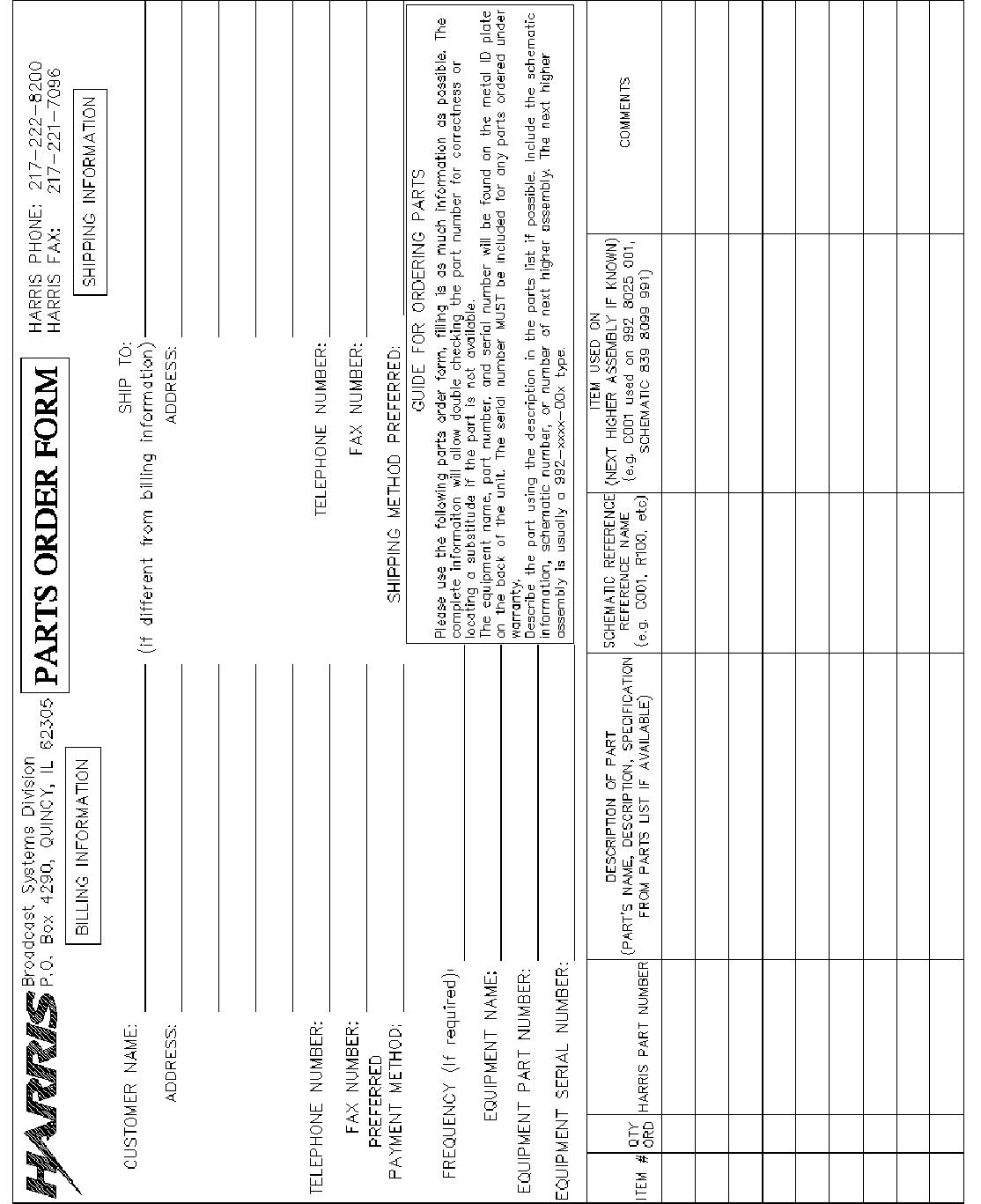
Replaceable Parts Service
Replacement parts are available 24 hours a day, seven days a week from the
HARRIS Service Parts Department. Telephone 217/222-8200 to contact the service
parts department or address correspondence to Service Parts Department, HARRIS
CORPORATION, Broadcast Systems Division, P.O. Box 4290, Quincy, Illinois
62305-4290, USA. The HARRIS factory may also be contacted through a FAX
facility (217/221-7096).
NOTE:
The # symbol used in the parts list means used with (e.g. #C001 = used with C001).

12/24/07 888-2685-001
WARNING: Disconnect primary power prior to servicing.
Manual Revision History
Ranger ™ Mobile Commissioning Manual
REV. DATE ECN Pages Affected
Rev A 9/20/07 Prelim. Created and Manual Sent To Review
Rev A1 12/24/07 Prelim. Added exciter settings.
MRH-1

888-2685-001 12/24/07
WARNING: Disconnect primary power prior to servicing.
MRH-2

12/24/07 888-2685-001
WARNING: Disconnect primary power prior to servicing.
888-2685-001 12/24/07
WARNING: Disconnect primary power prior to servicing.
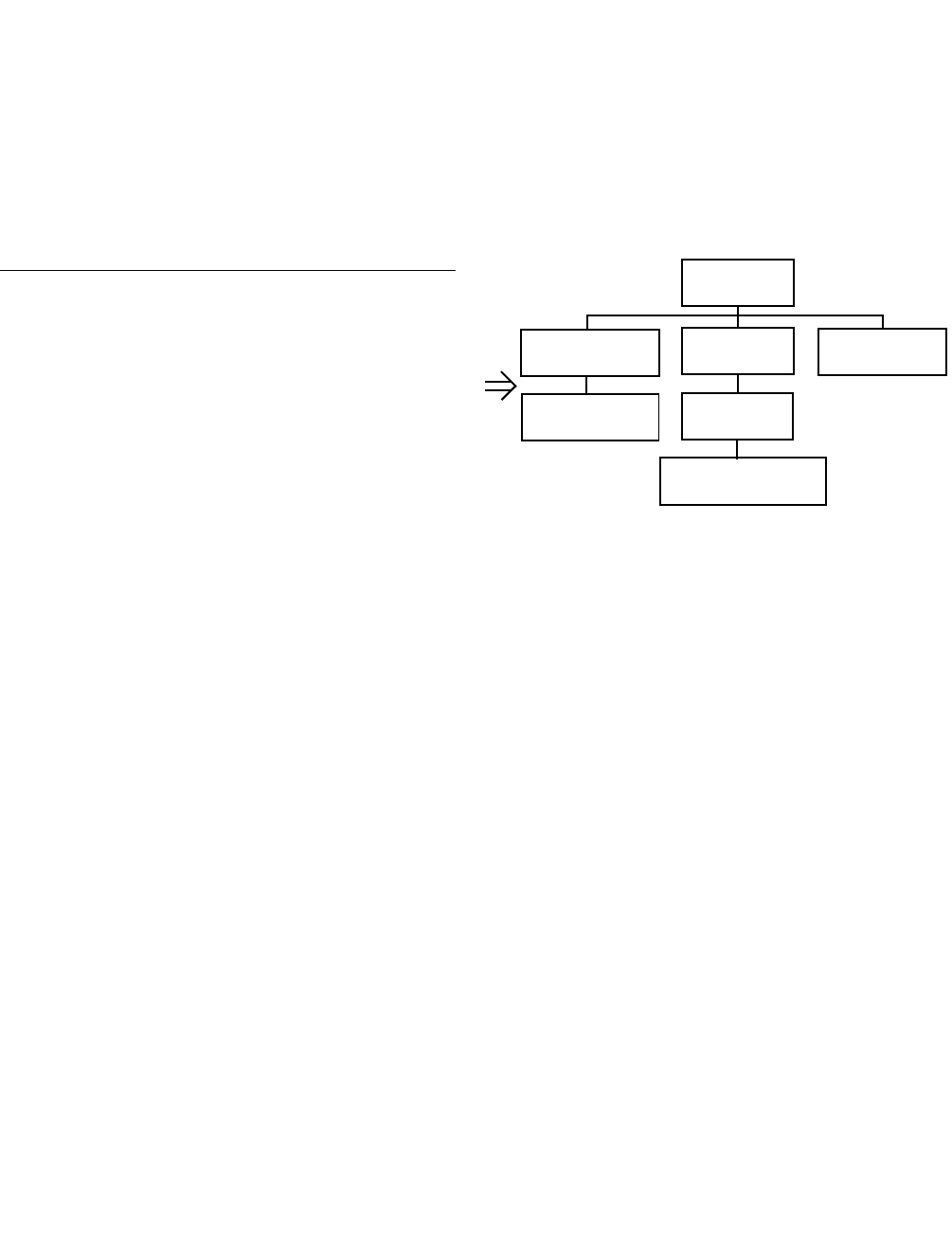
Guide to Using Harris Parts List Information
The Harris Replaceable Parts List Index portrays a tree structure with the major items being leftmost in the index. The
example below shows the Transmitter as the highest item in the tree structure. If you were to look at the bill of materials
table for the Transmitter you would find the Control Cabinet, the PA Cabinet, and the Output Cabinet. In the Replaceable
Parts List Index the Control Cabinet, PA Cabinet, and Output Cabinet show up one indentation level below the
Transmitter and implies that they are used in the Transmitter. The Controller Board is indented one level below the
Control Cabinet so it will show up in the bill of material for the Control Cabinet. The tree structure of this same index is
shown to the right of the table and shows indentation level versus tree structure level.
Example of Replaceable Parts List Index and equivalent tree structure:
Replaceable Parts List Index Part Number Page
Table 7-1. Transmitter 994 9283 001 7-2
Table 7-2. Control Cabinet 992 9244 002 7-3
Table 7-3. Controller Board 992 8344 002 7-6
Table 7-4. PA Cabinet 992 9400 002 7-7
Table 7-5. PA Amplifier 994 7894 002 7-9
Table 7-6. PA Amplifier Board 992 7904 002 7-10
Table 7-7. Output Cabinet 992 9450 001 7-12
The part number of the item is shown to the right of the description as is the page in the manual where the bill for that part
number starts. Inside the actual tables, four main headings are used:
•Table #-#. ITEM NAME - HARRIS PART NUMBER - this line gives the information that corresponds to the
•Replaceable Parts List Index entry;
•HARRIS P/N column gives the ten digit Harris part number (usually in ascending order);
•DESCRIPTION column gives a 25 character or less description of the part number;
•REF. SYMBOLS/EXPLANATIONS column 1) gives the reference designators for the item (i.e., C001, R102,
etc.) that corresponds to the number found in the schematics (C001 in a bill of material is equivalent to C1 on the
schematic) or 2) gives added information or further explanation (i.e., “Used for 208V operation only,” or “Used
for HT 10LS only,” etc.).
Inside the individual tables some standard conventions are used:
•A # symbol in front of a component such as #C001 under the REF. SYMBOLS/EXPLANATIONS column
means that this item is used on or with C001 and is not the actual part number for C001.
•In the ten digit part numbers, if the last three numbers are 000, the item is a part that Harris has purchased and has
not manufactured or modified. If the last three numbers are other than 000, the item is either manufactured by
Harris or is purchased from a vendor and modified for use in the Harris product.
•The first three digits of the ten digit part number tell which family the part number belongs to - for example, all
electrolytic (can) capacitors will be in the same family (524 xxxx 000). If an electrolytic (can) capacitor is found
to have a 9xx xxxx xxx part number (a number outside of the normal family of numbers), it has probably been
modified in some manner at the Harris factory and will therefore show up farther down into the individual parts
list (because each table is normally sorted in ascending order). Most Harris made or modified assemblies will
have 9xx xxxx xxx numbers associated with them.
The term “SEE HIGHER LEVEL BILL” in the description column implies that the reference designated part number will
show up in a bill that is higher in the tree structure. This is often the case for components that may be
frequency determinant or voltage determinant and are called out in a higher level bill structure that is more
customer dependent than the bill at a lower level.
Transmitter
994 9283 001
Control Cabinet
992 9244 002
Controller Board
992 8344 002
PA Cabinet
992 9400 002
PA Amplifier
992 7894 002
PA Amplifier Board
992 7904 002
Output Cabine
t
992 9450 001

888-2685-001 12/24/07
WARNING: Disconnect primary power prior to servicing.
! WARNING:
THE CURRENTS AND VOLTAGES IN THIS EQUIPMENT ARE DANGEROUS. PERSON-
NEL MUST AT ALL TIMES OBSERVE SAFETY WARNINGS, INSTRUCTIONS AND REG-
ULATIONS.
This manual is intended as a general guide for trained and qualified personnel who are aware of the
dangers inherent in handling potentially hazardous electrical/electronic circuits. It is not intended to
contain a complete statement of all safety precautions which should be observed by personnel in
using this or other electronic equipment.
The installation, operation, maintenance and service of this equipment involves risks both to
personnel and equipment, and must be performed only by qualified personnel exercising due care.
HARRIS CORPORATION shall not be responsible for injury or damage resulting from improper
procedures or from the use of improperly trained or inexperienced personnel performing such tasks.
During installation and operation of this equipment, local building codes and fire protection
standards must be observed.
The following National Fire Protection Association (NFPA) standards are recommended as reference:
- Automatic Fire Detectors, No. 72E
- Installation, Maintenance, and Use of Portable Fire Extinguishers, No. 10
- Halogenated Fire Extinguishing Agent Systems, No. 12A
! WARNING:
ALWAYS DISCONNECT POWER BEFORE OPENING COVERS, DOORS, ENCLO-
SURES, GATES, PANELS OR SHIELDS. ALWAYS USE GROUNDING STICKS AND
SHORT OUT HIGH VOLTAGE POINTS BEFORE SERVICING. NEVER MAKE INTERNAL
ADJUSTMENTS, PERFORM MAINTENANCE OR SERVICE WHEN ALONE OR WHEN
FATIGUED.
Do not remove, short-circuit or tamper with interlock switches on access covers, doors, enclosures,
gates, panels or shields. Keep away from live circuits, know your equipment and don’t take chances.
! WARNING:
IN CASE OF EMERGENCY ENSURE THAT POWER HAS BEEN DISCONNECTED.
! WARNING:
IF OIL FILLED OR ELECTROLYTIC CAPACITORS ARE UTILIZED IN YOUR EQUIP-
MENT, AND IF A LEAK OR BULGE IS APPARENT ON THE CAPACITOR CASE WHEN
THE UNIT IS OPENED FOR SERVICE OR MAINTENANCE, ALLOW THE UNIT TO COOL
DOWN BEFORE ATTEMPTING TO REMOVE THE DEFECTIVE CAPACITOR. DO NOT
ATTEMPT TO SERVICE A DEFECTIVE CAPACITOR WHILE IT IS HOT DUE TO THE
POSSIBILITY OF A CASE RUPTURE AND SUBSEQUENT INJURY.
12/24/07 888-2685-001
WARNING: Disconnect primary power prior to servicing.

888-2685-001 12/24/07
WARNING: Disconnect primary power prior to servicing.
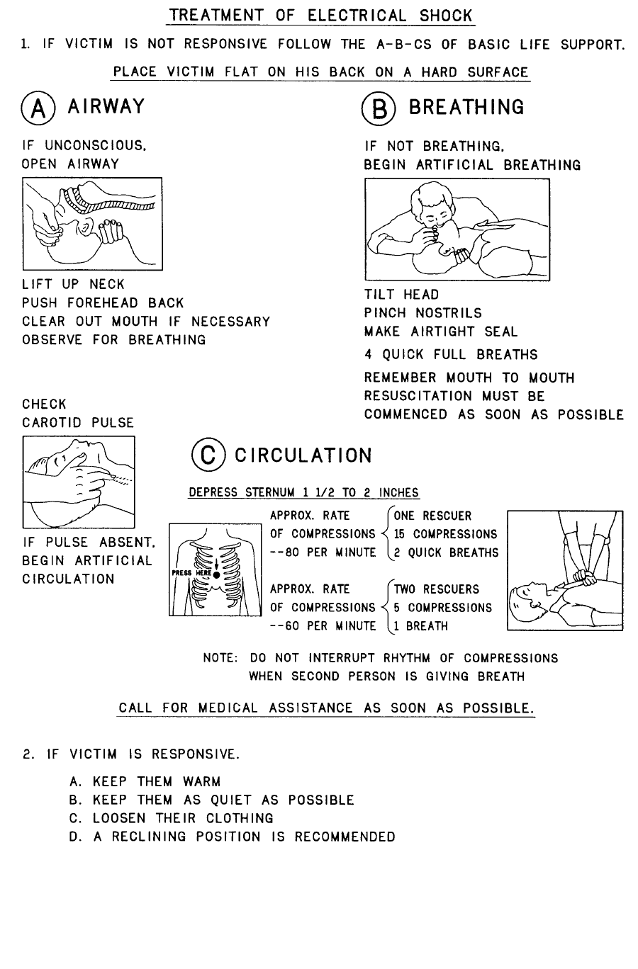
FIRST-AID
Personnel engaged in the installation, operation, maintenance or servicing of this equipment
are urged to become familiar with first-aid theory and practices. The following information is
not intended to be complete first-aid procedures, it is a brief and is only to be used as a
reference. It is the duty of all personnel using the equipment to be prepared to give adequate
Emergency First Aid and there by prevent avoidable loss of life.
Treatment of Electrical Burns
1. Extensive burned and broken skin
a. Cover area with clean sheet or cloth. (Cleanest available cloth
article.)
b. Do not break blisters, remove tissue, remove adhered particles of
clothing, or apply any salve or ointment.
c. Treat victim for shock as required.
d. Arrange transportation to a hospital as quickly as possible.
e. If arms or legs are affected keep them elevated.
NOTE:
If medical help will not be available within an hour and the victim is conscious and
not vomiting, give him a weak solution of salt and soda: 1 level teaspoonful of salt
and 1/2 level teaspoonful of baking soda to each quart of water (neither hot or
cold). Allow victim to sip slowly about 4 ounces (a half of glass) over a period of
15 minutes. Discontinue fluid if vomiting occurs. (Do not give alcohol.)
2. Less severe burns - (1st & 2nd degree)
a. Apply cool (not ice cold) compresses using the cleanest available
cloth article.
b. Do not break blisters, remove tissue, remove adhered particles of
clothing, or apply salve or ointment.
c. Apply clean dry dressing if necessary.
d. Treat victim for shock as required.
e. Arrange transportation to a hospital as quickly as possible.
f. If arms or legs are affected keep them elevated.
REFERENCE:
ILLINOIS HEART ASSOCIATION
AMERICAN RED CROSS STANDARD FIRST AID AND PERSONAL SAFETY
MANUAL (SECOND EDITION)

888-2685-001 12/24/07
WARNING: Disconnect primary power prior to servicing.

Table of Contents
12/24/07 888-2685-001 1
WARNING: Disconnect primary power prior to servicing.
Section 1
Introduction
Purpose of This Manual . . . . . . . . . . . . . . . . . . . . 1-1
Ranger Transmitter Models. . . . . . . . . . . . . . . . . . 1-2
System Block Diagrams . . . . . . . . . . . . . . . . . . . . 1-3
Transmitter Control System . . . . . . . . . . . . . . . . . 1-5
Graphical User Interface. . . . . . . . . . . . . . . . . . . 1-5
Control System Communications. . . . . . . . . . . . 1-5
In-System Programming or ISP . . . . . . . . . . . . . 1-6
Remote Control. . . . . . . . . . . . . . . . . . . . . . . . . . 1-6
PA Module. . . . . . . . . . . . . . . . . . . . . . . . . . . . . . . 1-6
Power Supplies . . . . . . . . . . . . . . . . . . . . . . . . . . . 1-8
Apex™ Exciter . . . . . . . . . . . . . . . . . . . . . . . . . . . 1-8
General Specifications. . . . . . . . . . . . . . . . . . . . . . 1-8
Section 2
Installation Verification & Initial Turn-
on
Introduction. . . . . . . . . . . . . . . . . . . . . . . . . . . . . . 2-1
Documentation . . . . . . . . . . . . . . . . . . . . . . . . . . . 2-4
Installation Drawings . . . . . . . . . . . . . . . . . . . . . 2-4
Installation Confirmation Checkboxes . . . . . . . . . 2-5
Transmitter Cabinet Placement . . . . . . . . . . . . . . . 2-5
Transmitter AC Connection . . . . . . . . . . . . . . . . . 2-5
Signal and Ground Connections . . . . . . . . . . . . . . 2-7
Interlock Connections . . . . . . . . . . . . . . . . . . . . . . 2-7
External Interlocks . . . . . . . . . . . . . . . . . . . . . . . 2-8
RF Mute Interlock . . . . . . . . . . . . . . . . . . . . . . . 2-8
3 Port Patch Panel Connection Confirmation . . . . 2-9
Motorized RF Switch Connections (if equipped) 2-10
PA and PS Module Installation . . . . . . . . . . . . . . 2-11
Initial Turn-On . . . . . . . . . . . . . . . . . . . . . . . . . . 2-12
Exciter Setup. . . . . . . . . . . . . . . . . . . . . . . . . . . 2-15
Verify Exciter Signal Connections. . . . . . . . . 2-16
AC Power. . . . . . . . . . . . . . . . . . . . . . . . . . . . 2-17
Verify Installation of the GPS 1PPS Signal . . 2-17
Verify Exciter Configuration . . . . . . . . . . . . . 2-18
Verify Configuration of Setup Screens . . . . 2-19
Verify Configuration of FPGA Screens . . . . . 2-20
Verify Configuration of Status Screens . . . . . 2-21
Normal Settings for Diagnostic Screens . . . . 2-22
RF Initial Turn ON . . . . . . . . . . . . . . . . . . . . . . 2-23
Parallel Remote Control Connections . . . . . . . . 2-26
Transmitter Control Functions, J13 and J14. . . 2-27
Remote Status Outputs, J15 & J16 . . . . . . . . . . . .2-28
Remote Power Metering, J17. . . . . . . . . . . . . . .2-30
Section 3
Operation and Adjustments
Introduction. . . . . . . . . . . . . . . . . . . . . . . . . . . . . . .3-1
Transmitter Control Panel. . . . . . . . . . . . . . . . . . . .3-1
Main Menu “Hardware” Buttons . . . . . . . . . . . . .3-2
Graphical User Interface (GUI) . . . . . . . . . . . . . . .3-2
Global Status and Navigation. . . . . . . . . . . . . . . .3-3
GUI Home Page . . . . . . . . . . . . . . . . . . . . . . . . . . .3-4
Drive Chain Main Menu . . . . . . . . . . . . . . . . . . . . .3-5
Drive Service . . . . . . . . . . . . . . . . . . . . . . . . . . . .3-6
Drive Meter Calibration . . . . . . . . . . . . . . . . . . . .3-6
Power Amp Main Menu . . . . . . . . . . . . . . . . . . . . .3-7
PA Faults . . . . . . . . . . . . . . . . . . . . . . . . . . . . . . .3-8
Module 3 strike Routine . . . . . . . . . . . . . . . . . .3-8
PA Meters. . . . . . . . . . . . . . . . . . . . . . . . . . . . . .3-10
PA Data. . . . . . . . . . . . . . . . . . . . . . . . . . . . . . . .3-11
PA Service . . . . . . . . . . . . . . . . . . . . . . . . . . . . .3-13
PA Setup (Gain Balance). . . . . . . . . . . . . . . . .3-14
Output Main Menu . . . . . . . . . . . . . . . . . . . . . . . .3-15
Output Service . . . . . . . . . . . . . . . . . . . . . . . . . .3-17
Module Phasing Procedure. . . . . . . . . . . . . . . . .3-18
Output Setup . . . . . . . . . . . . . . . . . . . . . . . . . .3-19
Forward and Reflected Power Calibrations . . . .3-20
Power Supply Main Menu . . . . . . . . . . . . . . . . . .3-21
PS Service . . . . . . . . . . . . . . . . . . . . . . . . . . . . .3-22
AC Mains Meter Calibration . . . . . . . . . . . . . .3-22
System Main Menu. . . . . . . . . . . . . . . . . . . . . . . .3-23
Control System. . . . . . . . . . . . . . . . . . . . . . . . . .3-24
System Log. . . . . . . . . . . . . . . . . . . . . . . . . . . . .3-25
System Service. . . . . . . . . . . . . . . . . . . . . . . . . .3-26
System Setup . . . . . . . . . . . . . . . . . . . . . . . . . .3-27
System Configuration . . . . . . . . . . . . . . . . . .3-28
Control Setup . . . . . . . . . . . . . . . . . . . . . . . .3-28
Touch Screen Calibration . . . . . . . . . . . . . . .3-29
Software Revisions (SW REVs) . . . . . . . . . . .3-31
Hardware Revisions . . . . . . . . . . . . . . . . . . .3-31
GUI Menu Structures . . . . . . . . . . . . . . . . . . . . . .3-32
Section 4
RF Testing
Introduction. . . . . . . . . . . . . . . . . . . . . . . . . . . . . . .4-1
Proof Testing and Report . . . . . . . . . . . . . . . . . . . .4-1

Table of Contents (continued)
2 888-2685-001 12/24/07
WARNING: Disconnect primary power prior to servicing.
Report Cover Page . . . . . . . . . . . . . . . . . . . . . . . 4-1
Table of Contents . . . . . . . . . . . . . . . . . . . . . . . . 4-2
Facilities Authorized in Construction Permit . . . 4-3
Transmitter Location. . . . . . . . . . . . . . . . . . . . . . 4-3
Transmitter Manufacturer ID Plate . . . . . . . . . . . 4-3
RF Power Summary . . . . . . . . . . . . . . . . . . . . . . 4-4
Antenna and Bandpass Filter Information . . . . . 4-4
System Block Diagram . . . . . . . . . . . . . . . . . . . . 4-5
Test Equipment List . . . . . . . . . . . . . . . . . . . . . . 4-6
Transmitter Power Output. . . . . . . . . . . . . . . . . . 4-6
Objective. . . . . . . . . . . . . . . . . . . . . . . . . . . . . . 4-6
Requirement(s) . . . . . . . . . . . . . . . . . . . . . . . . . 4-7
Setup and Test Equipment . . . . . . . . . . . . . . . . 4-7
Power Measurement Procedure . . . . . . . . . . . . 4-8
Power Measurement Test Results. . . . . . . . . . . 4-8
Frequency Tolerance . . . . . . . . . . . . . . . . . . . . . . 4-9
Objective. . . . . . . . . . . . . . . . . . . . . . . . . . . . . . 4-9
Requirement(s) . . . . . . . . . . . . . . . . . . . . . . . . . 4-9
Setup and Test Equipment . . . . . . . . . . . . . . . . 4-9
Frequency Tolerance Procedure . . . . . . . . . . . 4-10
Frequency Tolerance Test Results . . . . . . . . . 4-10
Non-Linear Precorrection (Shoulders & Amplitude
Response). . . . . . . . . . . . . . . . . . . . . . . . . . . . . 4-11
Objective. . . . . . . . . . . . . . . . . . . . . . . . . . . . . 4-11
Requirement(s) . . . . . . . . . . . . . . . . . . . . . . . . 4-11
Setup and Test Equipment . . . . . . . . . . . . . . . 4-11
Non-Linear Precorrection Procedure . . . . . . . 4-12
Non-Linear Precorrection Test Results. . . . . . 4-13
Out of Band Emissions . . . . . . . . . . . . . . . . . . . 4-13
Objective. . . . . . . . . . . . . . . . . . . . . . . . . . . . . 4-13
Requirement(s) . . . . . . . . . . . . . . . . . . . . . . . . 4-14
Setup and Test Equipment . . . . . . . . . . . . . . . 4-14
Out of Band Emissions Procedure . . . . . . . . . 4-15
Out of Band Emissions Test Results. . . . . . . . 4-16
Spurious Emissions (including 2nd & 3rd harmonics)
4-19
Objective. . . . . . . . . . . . . . . . . . . . . . . . . . . . . 4-19
Requirements . . . . . . . . . . . . . . . . . . . . . . . . . 4-19
Setup & Test Equipment. . . . . . . . . . . . . . . . . 4-20
Spurious Emissions Procedure . . . . . . . . . . . . 4-20
Spurious Emissions Test Results . . . . . . . . . . 4-22
Linear Precorrection (Group Delay & Amplitude
Response). . . . . . . . . . . . . . . . . . . . . . . . . . . . . 4-25
Objective. . . . . . . . . . . . . . . . . . . . . . . . . . . . . 4-25
Requirements . . . . . . . . . . . . . . . . . . . . . . . . . 4-25
Setup & Test Equipment. . . . . . . . . . . . . . . . . 4-26
Spurious Emissions Procedure . . . . . . . . . . . . 4-26
Spurious Emissions Test Results . . . . . . . . . . 4-27
Linear Precorrection Procedure . . . . . . . . . . . 4-30
Linear Precorrection Test Results . . . . . . . . . 4-31
Modulation Error Ratio (MER) . . . . . . . . . . . . 4-32
Objective . . . . . . . . . . . . . . . . . . . . . . . . . . . . 4-32
Requirement(s). . . . . . . . . . . . . . . . . . . . . . . . 4-32
Setup and Test Equipment . . . . . . . . . . . . . . . 4-32
Modulation Error Measurement Procedure . . 4-34
Modulation Error Results. . . . . . . . . . . . . . . . 4-35
Meter Readings. . . . . . . . . . . . . . . . . . . . . . . . . 4-36
System VSWR Plots. . . . . . . . . . . . . . . . . . . . . 4-37
Software Versions . . . . . . . . . . . . . . . . . . . . . . . 4-39
Appendix A - Linux Data Capture & Processing 4-40
Introduction. . . . . . . . . . . . . . . . . . . . . . . . . . . . 4-40
Required Equipment . . . . . . . . . . . . . . . . . . . . . 4-40
Block Diagram . . . . . . . . . . . . . . . . . . . . . . . . . 4-40
1PPS Source Setup . . . . . . . . . . . . . . . . . . . . . . 4-41
FSQ Connections . . . . . . . . . . . . . . . . . . . . . . 4-41
FSQ Settings. . . . . . . . . . . . . . . . . . . . . . . . . . 4-43
Setting Static IP Address for FSQ & Linux Machine
4-43
For the FSQ . . . . . . . . . . . . . . . . . . . . . . . . . . 4-44
For Linux Laptop . . . . . . . . . . . . . . . . . . . . . . 4-44
Capturing and Processing Data. . . . . . . . . . . . . 4-45
Setting Flo Signal Parameters . . . . . . . . . . . . 4-45
Performing the Measurement. . . . . . . . . . . . . 4-46
Looking at the Results . . . . . . . . . . . . . . . . . . 4-46
Moving Results to Flash Drive. . . . . . . . . . . . 4-46
Appendix B - Generating a CW Tone . . . . . . . . . 4-48
Section 5
Replacement Procedures
Introduction . . . . . . . . . . . . . . . . . . . . . . . . . . . . . . 5-1
PA Module Removal . . . . . . . . . . . . . . . . . . . . . . . 5-1
CZ1000F PA Module Air Block. . . . . . . . . . . . . 5-1
PA Module Pallet Replacement . . . . . . . . . . . . . 5-3
Power Supply Module Replacement . . . . . . . . . . . 5-6
Circulator Removal/Replacement . . . . . . . . . . . . . 5-7
Blower Assembly Removal. . . . . . . . . . . . . . . . . . 5-9
Section 6
ISP (In-System Programming)
Introduction . . . . . . . . . . . . . . . . . . . . . . . . . . . . . . 6-1
Installing the ISP Program. . . . . . . . . . . . . . . . . . . 6-2
ISP Procedures. . . . . . . . . . . . . . . . . . . . . . . . . . . . 6-2

Table of Contents (continued)
12/24/07 888-2685-001 3
WARNING: Disconnect primary power prior to servicing.
Control System ISP Procedure . . . . . . . . . . . . . . 6-3
PA Module ISP Procedure . . . . . . . . . . . . . . . . . 6-8
ISP Errors . . . . . . . . . . . . . . . . . . . . . . . . . . . . . 6-11

Table of Contents (continued)
4 888-2685-001 12/24/07
WARNING: Disconnect primary power prior to servicing.

12/24/07 888-2685-001 1-1
WARNING: Disconnect primary power prior to servicing.
Ranger Commissioning Manual
Section 1
Introduction 1
1.1 Purpose of This Manual
This technical manual contains the information pertaining to the commissioning of the Ranger™
Series, solid-state, UHF transmitter, with APEX exciter, featuring FLOR Technology. The
various sections of this technical manual provide the following types of information.
•Section 1, Introduction, provides general manual layout, equipment description,
block diagram and general specifications.
•Section 2, Installation Confirmation, provides step by step instructions to confirm
installation has been completed.
•Section 3, Operation, contains information regarding transmitter operation and GUI
(graphical user interface) screen content.
•Section 4, RF Testing, provides examples of measurements that are required to verify
transmitter RF performance. Examples are configured in a report format.
•Section 5, Replacement Procedures, outlines required procedures for removal and
replacement of components.
•Section 6, ISP (In System Programming) instructions for reprogramming transmitter
software.

1-2 888-2685-001 12/24/07
WARNING: Disconnect primary power prior to servicing.
Section 1 Introduction Ranger Commissioning Manual
1.2 Ranger Transmitter Models
The Ranger Series™ transmitter utilizing FLOTM technology is available in 2 power levels as
listed in Table 1-1.Both systems are designed to use external (low loss) mask filters for maximum
usable RF power output.
The Ranger control system is adapted from the state-of-the-art Atlas Series UHF solid state
transmitter using a very simple control panel and easy to use Graphical User Interface or GUI.
It consists of a single cabinet with an Apex exciter, a single power supply and one or two PA
modules depending on the model.
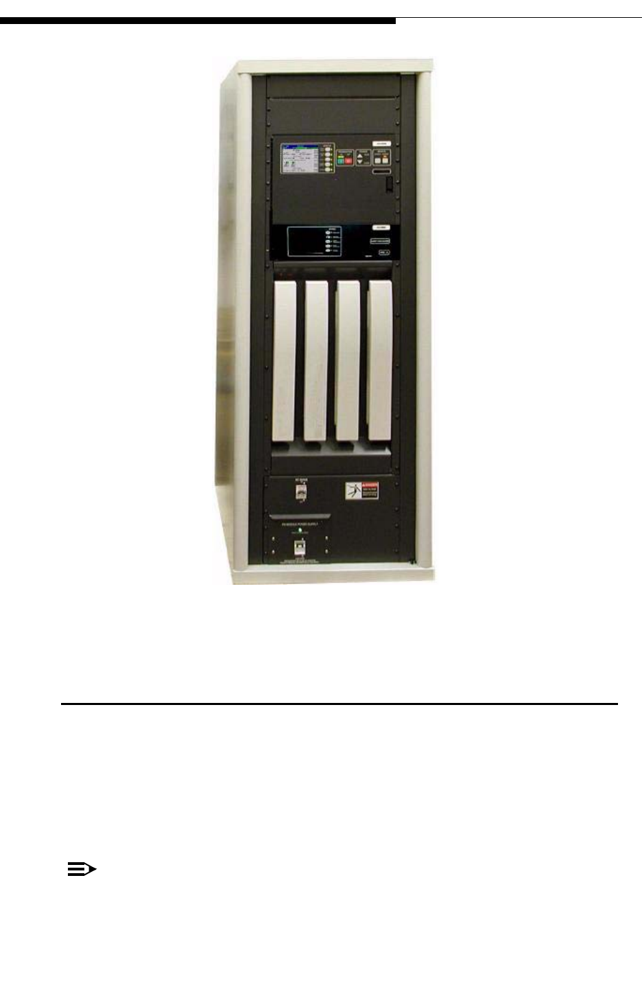
Figure 1-1 at right, shows a front view of the Ranger transmitter. All Ranger models look identical
due to the use of false module covers for the 2 or 3 right-hand slots.
Table 1-1 Ranger Series™ Transmitter Models
Tx Models PA
Modules Power Supplies Power
before Filter Filter location
CZ500F 1 1 375W External
CZ1000F 2 1 750W External
NOTE: All power levels given in average power assuming the use of FLO technology modulation
12/24/07 888-2685-001 1-3
WARNING: Disconnect primary power prior to servicing.
Section 1 Introduction
Ranger Commissioning Manual
Figure 1-1 Ranger Transmitter - Front View
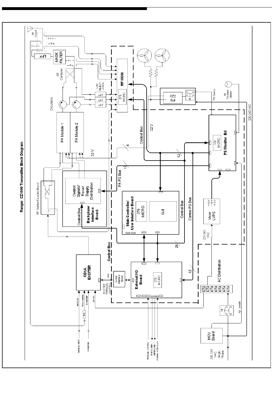
1.3 System Block Diagrams
Figure 1-2 shows the system block diagram of the CZ1000F Ranger Transmitter. The CZ500F
model has only 1 PA Module and is identical to the CZ1000F with the following items deleted:
• PA Module 2, along with its circulator and reject attenuator
• 3dB Hybrid Combiner and Reject attenuator
NOTE:
For components locations refer to Figure 2-1 on page 2-2 and Figure 2-3 on page
2-6.
1-4 888-2685-001 12/24/07
WARNING: Disconnect primary power prior to servicing.
Section 1 Introduction Ranger Commissioning Manual
Figure 1-2 Ranger Series™ System Block Diagram

12/24/07 888-2685-001 1-5
WARNING: Disconnect primary power prior to servicing.
Section 1 Introduction
Ranger Commissioning Manual
1.4 Transmitter Control System
The transmitter uses a distributed architecture control system. This means that each transmitter
sub-system is responsible for its own monitoring and protection and simply reports back to the
Main Controller for display on the GUI (Graphical User Interface) or to a remote interface. The
heart of the system is the 376 Micro Module which is used in all of the transmitter systems for
control, monitoring and protection. The Micro Module is used on each of the following
controllers and sub-systems:
a. Main Controller Board - This board is responsible for transmitter control and
monitoring. However, with the distributed control architecture, it is not directly
responsible for protection of the individual transmitter components. It merely
gathers all status and fault data from the individual sub-systems and reports that
information to the operator. The Main Controller is responsible for system level
control (issues which effect multiple systems) since it is the only part of the con-
trol system which can monitor the entire transmitter.
b. RF Monitor Board - Responsible for cabinet VSWR protection and monitoring of
combiner reject loads. Reports directly to the Main Controller.
c. Power Supply Monitor Board - Responsible for control and monitoring of the PA
power supply and distribution of the low voltage. Also responsible for monitoring
the cooling system including temperature and air pressure. Reports directly to the
Main Controller.
d. External I/O Board - Provides all customer interface connections including paral-
lel remote control. Reports directly to the Main Controller.
e. PA Module Controllers (1 in each module) - This is not actually a 376 micro
module but is a micro controller and is responsible for protection and control of
the PA Module. Reports directly to the Main Controller Board via the CAN bus.
1.4.1 Graphical User Interface
The front panel user interface is a 1/4 VGA, LCD touchscreen display. The touchscreen display is
used to monitor the transmitter. Hardware buttons for the primary transmitter functions such as
ON, OFF, RAISE and LOWER are provided on the overlay panel next to the display.
1.4.2 Control System Communications
The control system uses a serial communications system called a CAN bus. CAN stands for
Controller Area Network. The CAN bus is a closed loop serial network operated by the Main
Controller Board. Each circuit board and module connected to the CAN bus is considered a node
and therefore has a specific address. This allows the Main Controller to gather information from
all parts of the transmitter and display it on the GUI. One big advantage of the CAN bus is that it

1-6 888-2685-001 12/24/07
WARNING: Disconnect primary power prior to servicing.
Section 1 Introduction Ranger Commissioning Manual
requires only 2 wires of the system control ribbon cable, eliminating a large amount of discrete
wiring which would otherwise be required.
For redundancy, the CAN bus is backed up by parallel, hardwired, control lines that allow the
transmitter to stay on the air even if the CAN bus fails. The parallel control lines also provide the
instantaneous OFF and RF MUTE commands necessary for transmitter protection.
1.4.3 In-System Programming or ISP
The use of the CAN bus for communication between the various Micro Modules in the transmitter
also allows for easy updating of the software used in each transmitter sub-system via a serial port
connection to an external computer. This is referred to as In-System Programming or ISP.
The real benefit of In-System Programming is that it allows any or all of the transmitter software
to be updated without removing or replacing any firmware ICs. The Harris ISP program is
provided on the CD-ROM accompanying this manual along with all of the transmitter software as
it shipped from the factory. The Harris ISP program is easy to use and it only takes a few minutes
to load or update software.
NOTE:
Software does not need to be loaded into the transmitter unless new components
are installed or an update is sent from Harris. The transmitter, as shipped from the
factory, is preloaded and ready to run.
1.4.4 Remote Control
The Ranger Series™ transmitter has all of the standard parallel remote control, status and analog
metering connections for use with a third party remote control system. For a complete listing of
the remote control connections, see Table 2-1, Table 2-2 and Table 2-3 at the end of section 2.
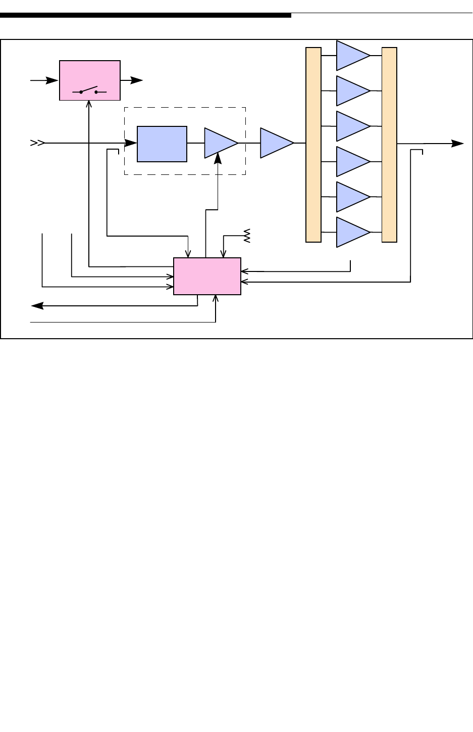
1.5 PA Module
The Ranger Series™ PA Module utilizes the same LDMOS amplifier module as used in the
Diamond Series DTV transmitter. Each PA Module will produce up to 400W average power
output. A block diagram of the PA module is shown in Figure 1-3.
12/24/07 888-2685-001 1-7
WARNING: Disconnect primary power prior to servicing.
Section 1 Introduction
Ranger Commissioning Manual
Figure 1-3 PA Module Block Diagram
Each PA module consists of the following components:
a. PA Module Controller Board - Responsible for all monitoring and protection of
the module. Reports to the transmitter Main Controller via the CAN bus but is
also connected to the parallel control lines in case the CAN bus is not operational.
Also provides for FET switching and distribution of the +32Vdc power to the
driver and PA pallets and sensing of driver and pallet currents.
b. Phase and Gain Board - Provides for module phase and gain adjustments to mini-
mize the PA module combiner reject power for the CZ1000F.
c. One LDMOS Driver Pallet - Provides enough power to drive the 6 way splitter
and the inputs to the power amplifier pallets.
d. Six-way Pallet Splitter and Combiner.
e. Six (6) LDMOS Amplifier Pallets - When combined, they provide up to 400
watts of average power at the output of the module. These pallets are field
replaceable.
f. RF Output Directional Coupler - Samples both Forward and Reflected power for
metering, module ALC and module VSWR protection.
AB
PHASE
&
GAIN
CONTROL
BOARD
SS RELAY
AB
AB
AB
AB
AB
AB A
LDMOS FAULT
FWD
TEMP
Pin
+32V
BIAS
RF IN
TO MAIN CONTROLLER
SWITCHED
+32V
ON/OFF
MODULE ENABLE
DC
SHORT
32V
MON
RF
OUT
1-8 888-2685-001 12/24/07
WARNING: Disconnect primary power prior to servicing.
Section 1 Introduction Ranger Commissioning Manual
Each Ranger Series™ PA Module is a self-contained transmitter (except for the power supply)
with its own internal control, monitoring and protection. The modules only receive basic On/Off,
Mute, Restart, Phase and Gain commands from the transmitter control system. This means that
each module will protect itself without relying on the system controller.
1.6 Power Supplies
A single +32 Vdc switching power supply is used to provide the DC voltage to the PA modules
within each PA cabinet. The power supply can provide power for 1 or 2 PA modules. The control
system in the PA Cabinet is powered by a self contained low voltage power supply with +/-15Vdc
and +7.5Vdc outputs.
1.7 Apex™ Exciter
For information on setup and operation of the Apex Exciter utilizing FLOR technologies refer to
the separate exciter manual, 888-2604-001. The exciter manual is bundled with the transmitter
documentation for shipment.
1.8 General Specifications
Table 1-2 provides the performance specifications for the Ranger series transmitters.
NOTE:
All specifications subject to change without notice
Table 1-2 Ranger Performance Specifications
Item Unit
sConditions Value
General
Frequency Range Mhz Any specified FCC
Channel 14-69 470-806 Mhz
Channel Bandwidth Mhz FLO Technologies COFDM standard 6, 7 or 8 Mhz
Output Power before Mask
Filter WAt 36 dB shoulders (measured +/-3.00
MHz from center of 6 MHz channel) CZ500F - 375W
CZ1000F - 750W
RF Load Impedance Ohms 50 Ohms
RF Load VSWR Over specified TV channel 1.1:1
Output Connector 1-5/8” EIA Flanged
12/24/07 888-2685-001 1-9
WARNING: Disconnect primary power prior to servicing.
Section 1 Introduction
Ranger Commissioning Manual
Data Input
Input Rate Mb/s 270
Impedance Ohms 75
Standard DVB-
ASI EN 50083-9
Connector BNC Female
External Frequency Reference Input
Frequency Mhz 10 Mhz
Impedance Ohms 50 Ohms
Level dBm Sinusoidal Waveform 0 to +10 dBm
Connector BNC Female
Performance
Modulation Error Ration
(MER) dB Measured at transmitter output > 33dB
Shoulder Level dB Measured at transmitter output before
filter, for 6 MHz channel, Fc +/- 3 MHz > 36 dB
Carrier Suppression dB > 20
I/Q Imbalance dB Residual Sideband Level > 50
Frequency Tolerance
(without external reference) Hz for at least 24 hrs. 1 x 10⁻⁸
Frequency Tolerance (with
external reference) Hz for at least 24 hrs. 1 x 10⁻⁹
Pilot Frequency Stability Hz With External Reference Less than +/- 3 Hz
Stability of Output Power %Over entire operating temperature range
and indefinite time period +/-10%, or less
Phase Noise
Frequency Offset Relative to Carrier
Frequency Phase Noise
100 Hz -80
1 kHz -90
10 kHz -95
100 kHz -110
1 MHz -120
> 1 MHz -120
Spurious Radiation
Conducted Spurious
Radiation dBc Measured at transmitter outptut before
filter < -30
AC Line
Item Unit
sConditions Value
1-10 888-2685-001 12/24/07
WARNING: Disconnect primary power prior to servicing.
Section 1 Introduction Ranger Commissioning Manual
AC Line Voltage VAC Single Phase 50/60 Hz 208/240 VAC
AC Line Voltage Variation %+/-10%
Power Factor > 0.97
Overall Efficiency (Typical) %AC power to RF average power 20% (for CZ500F &
CZ1000F)
Power Consumption
(Typical) kW 2.5kW for CZ500F
5 kW, for CZ1000F
Environmental
Operational Temperature
Range o C Derate 2 degree C per 300m AMSL 0 - 45
Operational Relative
Humidity %Non-condensing 0 - 90
Guaranteed Specification
Temperature Range oC5-45
Storage Temperature oC-20+60
Maximum Altitude Ft. AMSL (Above Mean Sea Level) 7500
Cooling Method Air Cooled
Residual Heat Transferred
to Room kW Normal operating conditions 2.0kW for CZ500F
4.0 kW, for CZ1000F
Acoustic Noise dBA Measured 1m from front of cabinet <67 dBa
Physical
Dimensions In Cabinet only 72H x 27.6W x 40D
Weight Lbs Does not include options CZ500F 600 Lbs
CZ1000F 1000 Lbs
Cl-PS-02-003 Ranger Performance Spec
Item Unit
sConditions Value

12/24/07 888-2685-001 2-1
WARNING: Disconnect primary power prior to servicing.
Ranger Commissioning Manual
Section 2
Installation Verification &
Initial Turn-on 2
2.1 Introduction
This section includes the information necessary for installation confirmation prior to
initial system start-up of the Ranger™ Series, solid state UHF transmitter. Information
is included for single and dual PA module configurations. Due to the modular nature of
the Ranger, all models have similar installation and testing procedures.
! CAUTION:
THE PROCEDURE THAT FOLLOWS ASSUMES THAT THE INSTALLATION
PROCESS HAS BEEN COMPLETED AND THAT ALL TESTING OUTLINED IN
SECTION 2 OF THE RANGER MOBILE TRANSMITTER MANUAL HAS BEEN
COMPLETED. IF AT SOME POINT DURING THIS CONFIRMATION PROCESS
THE COMMISSIONING AGENT DISCOVERS THAT INSTALLATION STEPS
HAVE BEEN MISSED THEN THE INSTALLATION STEPS OUTLINED IN THE
TRANSMITTER MANUAL SHOULD BE REPEATED IN THEIR ENTIRETY
BEFORE PROCEEDING WITH COMMISSIONING.
2-2 888-2685-001 12/24/07
WARNING: Disconnect primary power prior to servicing.
Section 2 Installation Verification & Ranger Commissioning Manual
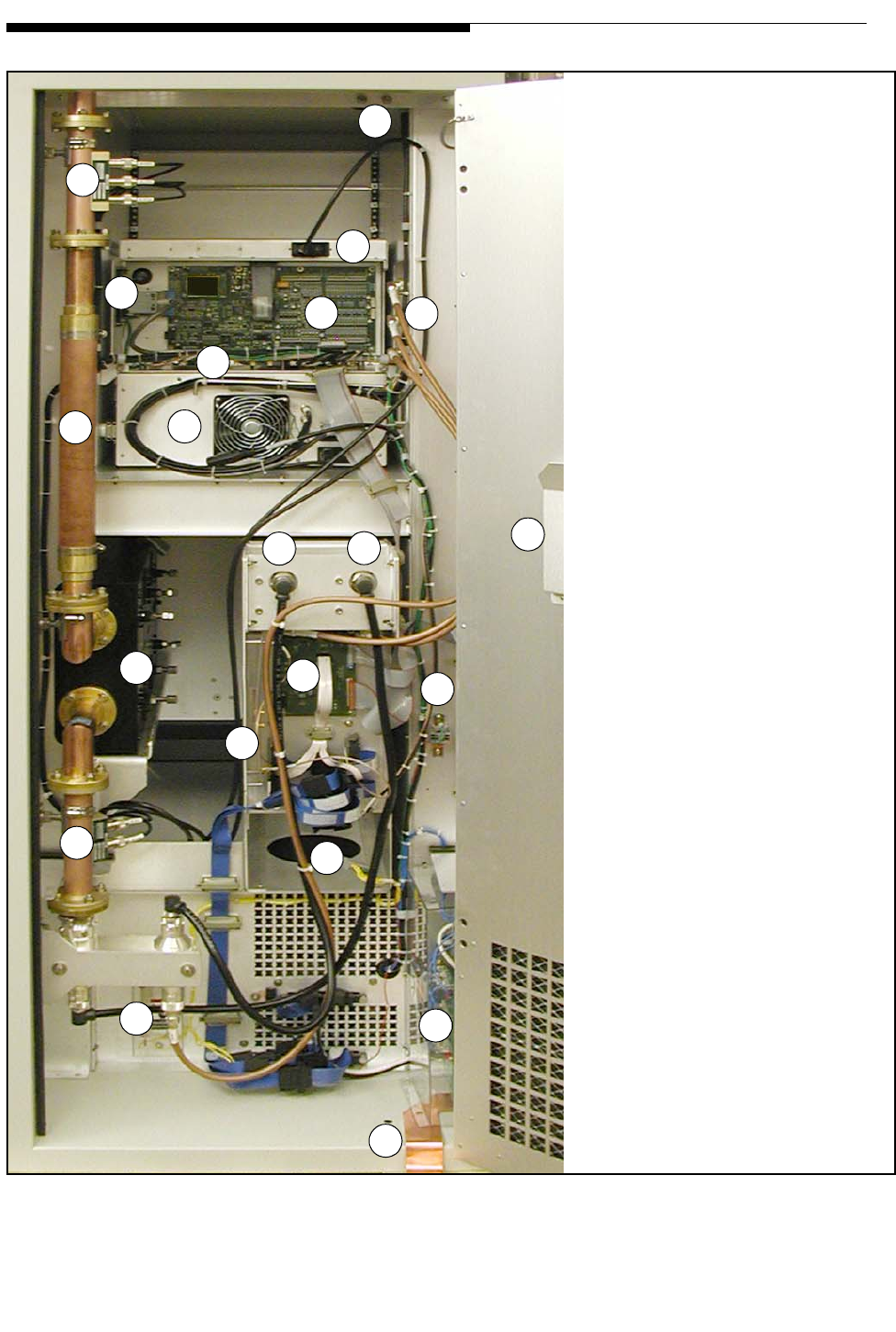
Figure 2-1 Component Locator, Cabinet Rear View
C
DEF
G
H
JKL
MN
O
P
RS
TU
V
A
B
I
D
A - ASI and optional 10MHz
reference inputs for the exciter
B - Total Forward and Reflected
power samples (after filter) and
RTAC sample for the exciter
C -Low Voltage Power Supply
switch and fuse assembly
D - Exciter Interface Board
E - External I/O Board. Remote
Control connections are directly
above and below the marker
F - Reject Attenuators for PA
module circulators and PA module
3dB hybrid combiner
G - RF Monitor Board (laying flat)
H - Lowpass Filter
I - Apex Exciter
J and K - Circulator output
connections to PA module combiner
L - PA Module glove holder
M - Mask Filter. Located externally
on CZ500F and CZ1000F
N - Backplane Interface Board
O - RF Splitter Board
P - TB2, PS enable lines
R - Forward and Reflected Power
samples before the filter
S - Blower assembly
(shown removed)
T - 3dB Hybrid Combiner
U - AC Input and MOV board
V - Ground strap (an alternative
ground block is also provided
on top of the cabinet)
12/24/07 888-2685-001 2-3
WARNING: Disconnect primary power prior to servicing.
Section 2 Installation Verification &
Ranger Commissioning Manual
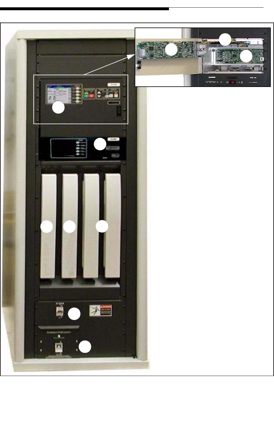
Figure 2-2 Component Locator, Cabinet Front View
A
B
CDE
F
G
HI
J
A - Control panel with GUI Touchscree
n
B - Apex Exciter
C - PA Module #1
D - PA Module #2 for CZ1000F (blank
panel in CZ500F)
E - Blank panels
F - Control Circuit Breaker, CB1.
Supplies power for the LV PSU (J).
G - PA Power Supply (and Circuit
Breaker)
H - Main Controller Board
I - Power Supply Monitor Board
J - Low Voltage Power Supply (LV PSU
)

2-4 888-2685-001 12/24/07
WARNING: Disconnect primary power prior to servicing.
Section 2 Installation Verification & Ranger Commissioning Manual
2.2 Documentation
The following is a list of documentation that ships with the transmitter. This
documentation should be available for reference during the commissioning process.
The top level Document Package numbers for each transmitter model are shown below:
•CZ500F & CZ1000F: 988-2687-001
A Document Package includes:
1. 888-2685-001 Commissioning Manual (this technical manual)
2. 888-2497 RangerTM Mobile Series Transmitter Manual
3. 888-2604-001 Apex Exciter using FLOR Technology Operating Manual
4. Drawing Package with a complete set of installation schematics for the
transmitter system
The included CD-ROM contains:
1. Transmitter control software files of the same revision as loaded into the
transmitter at the factory
2. ISP (In-System Programming) software application which is used to install
software upgrades into the transmitter controllers.
3. An Acrobat (pdf) version of the transmitter Technical Manual.
2.2.1 Installation Drawings
It is recommended that you look through the drawing package to familiarize yourself
with the information available. Although drawings are provided for all assemblies in the
transmitter, most of the installation and planning information is given in the following
drawings (in the supplied drawing package):
a. Transmitter Outline Drawing - 843-5560-071 - Shows physical connection points
for AC and control conduits and RF output. Also gives cabinet dimensions,
required cabinet clearances and a table of basic requirements for both models.
b. Transmitter Wiring Diagram - 843-5560-001 - Interconnection wiring diagram
for all assemblies inside the transmitter cabinet.
c. AC Flow Diagram - 843-5560-098 - Shows external AC wiring requirements
along with minimum wire and breaker sizing for each model.
12/24/07 888-2685-001 2-5
WARNING: Disconnect primary power prior to servicing.
Section 2 Installation Verification &
Ranger Commissioning Manual
d. RF Flow Diagram - 843-5560-097 - Shows external RF connections and possible
layout for patch panel and dummy load.
e. Ranger External I/O Connections - 843-5560-105 - Shows connections to the
External I/O board for an RF patch panel or motorized switch.
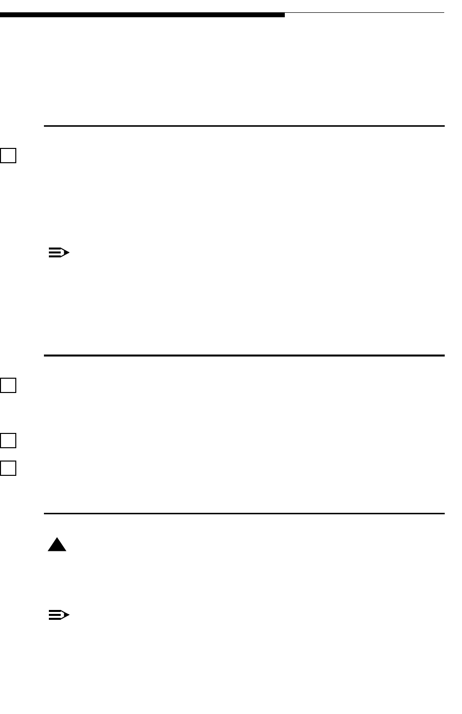
2.3 Installation Confirmation Checkboxes
Located to the left of each important step in the commissioning procedure is a checkbox
like the one to the left of this paragraph. As each step in the procedure is completed, the
box should be checked. This provides an opportunity for review at the end of the
procedure to insure that no steps were skipped. The primary goal of each step is also
in bold letters, with the rest of the paragraph being support information toward that
goal.
NOTE:
In case of discrepancy between the connections listed in the schematics versus
the information given in this installation section, the wiring information in the
schematics should be considered the most accurate. All connections listed in this
section should be verified with the schematics before initial turn on.
2.4 Transmitter Cabinet Placement
The transmitter cabinet as approximately 3 feet of clearance on each side and in
the back. The front of the transmitter has a clearance of at least 5 feet to allow for
access to the PA and power supply modules.
The transmitter is secured to floor as required by local codes.
The transmitter is level and solid (not rocking).
2.5 Transmitter AC Connection
! WARNING:
DISABLE AND LOCK OUT STATION PRIMARY POWER BEFORE PRIMARY POWER
CABLES ARE CONNECTED TO THE EQUIPMENT.
NOTE:
The Ranger transmitter is equipped for single phase 208/240Vac at 50/60Hz. If
voltage variations in excess of +/-10% are anticipated, the transmitter power
2-6 888-2685-001 12/24/07
WARNING: Disconnect primary power prior to servicing.
Section 2 Installation Verification & Ranger Commissioning Manual
input must be equipped with automatic voltage regulators (optional equipment)
capable of correcting the mains voltage.
The Primary AC conduit is securely attached to the top of the transmitter cabinet.
The top of the transmitter cabinet has a pre-cut hole for a 3/4” conduit connection. For
Conduit connections to the transmitter refer to the Transmitter Outline Drawing 843-
5560-071, Top View. The AC input is the routed straight down to TB1, shown in Figure
2-3.
The AC supply wires have been connected to TB1-2 and TB1-4. The AC Flow
diagram shows ac wiring to the transmitter along with recommended wire gauge and
breaker size. Wire gauge and breaker size are installed as outlined in the Figure 2-
3.
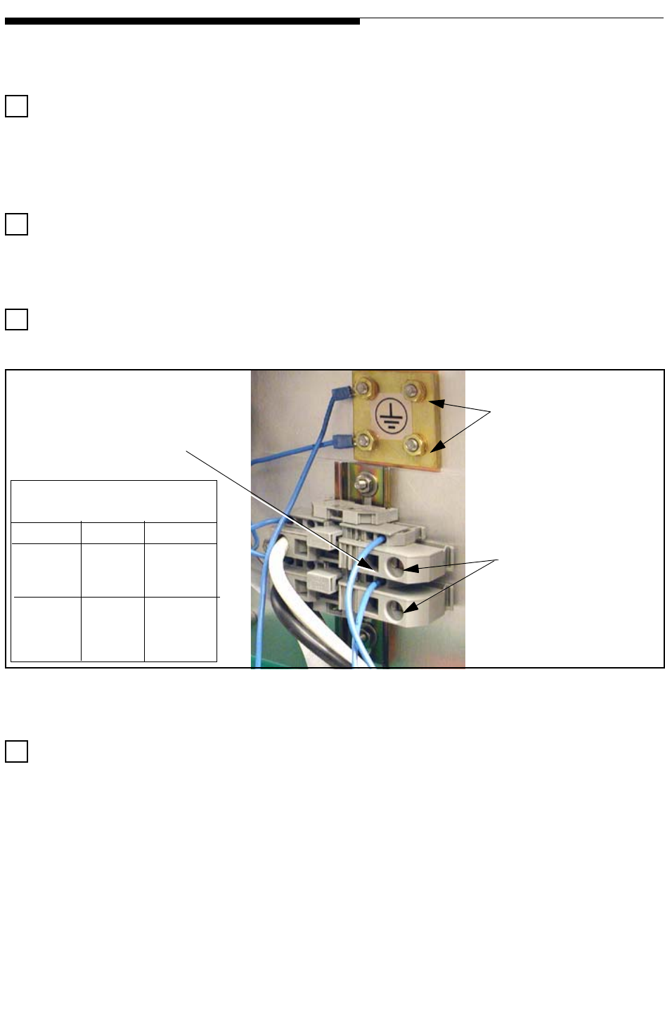
The safety ground wire is attached to one of the terminals on the grounding block.
Figure 2-3 AC and Safety Ground Connections
Verify that the AC wires are securely connected to the primary AC terminal block
TB1. Be sure that the wires are fully seated and that the insulating jacket has not
been pinched between the contact jaws inside the connector.
Safety Ground Connection
TB1 AC Connections
Place flat blade screwdriver into
square hole and gently pry toward
front of transmitter until connector
in round hole is open far enough
to insert the AC input wire
Recommended Wire and
Breaker Sizes:
Model Breaker Wire size
CZ500F 20A 10 awg
CZ1000F 40A 8 awg
12/24/07 888-2685-001 2-7
WARNING: Disconnect primary power prior to servicing.
Section 2 Installation Verification &
Ranger Commissioning Manual
2.6 Signal and Ground Connections
NOTE:
Control and signal wires should never be run in the same conduit with any AC
wiring. A separate conduit should be used for control/signal cables.
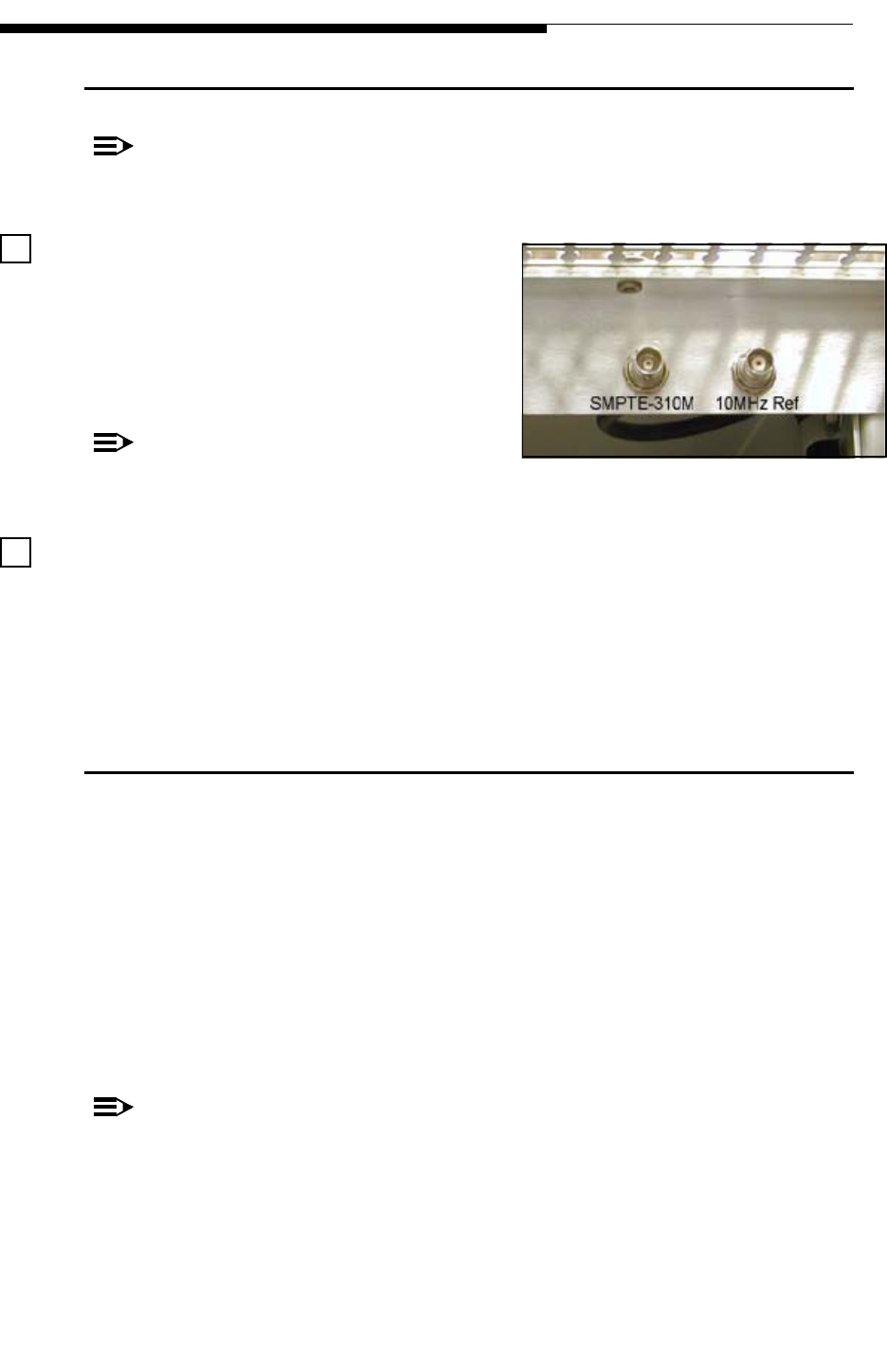
Confirm that the ASI input is connected to
the terminal (may be labeled SMPTE 310M
as seen in the photo). There are 2 bulkhead
BNC connectors located just inside the back
door at the top of the cabinet as shown to the
right.
NOTE:
Note that the 10Mhz reference is
optional.
Verify that a ground strap is connected from the transmitter cabinet to the station
ground. There is a brass ground block located on top of the cabinet or a strap coming
out the back of the cabinet (only one should be used). For connection to the top of the
cabinet, remove the block, punch holes in the copper ground strap and then mount the
strap under the block. The loose strap at the bottom of the cabinet should be soldered to
the station ground strap. The copper strap must be at least 2" wide.
2.7 Interlock Connections
There are 2 types of interlock connections for the Ranger:
• External Interlock which shuts the transmitter off and requires the user to
give an ON command (local or remote) to turn the transmitter back on. Used
for protection of personnel and equipment. For more information see "2.7.1
External Interlocks" on page 2-8.
• RF Mute Interlock which only mutes the rf drive and therefore reduces the
transmitter power output to zero. This interlock is meant to be used for a
motorized RF switch or possibly a dummy load thermal interlock.
NOTE:
To operate the transmitter without any interlock connections requires 3 jumpers:
• J18-1 to J18-8 (defeats the External Interlocks)
• J18-9 to J18-12 (defeats the RF Mute Interlocks)
• J14-1 to J14-3 (defeats the RF Switch Status feedback interlock)
2-8 888-2685-001 12/24/07
WARNING: Disconnect primary power prior to servicing.
Section 2 Installation Verification & Ranger Commissioning Manual
2.7.1 External Interlocks
The transmitter has inputs for up to four
external interlocks on the External I/O
Board. Note that these 4 connections
comprise one interlock with 4 series
connection points. The transmitter, as
shipped from the factory, has no external
interlock connections. The Ranger External
I/O Connection schematic (843-5560-105 or
843-5549-141, sht 20) shows that Interlock
#1, J18-1 to J18-2, is usually used by a 3
port patch panel. The other three are to be
used at the customers discretion.
IMPORTANT:
The External Interlock circuit requires a closed connection between all of the fol-
lowing terminals on the External I/O Bd to turn the transmitter on:
• J18 pins 1-2 (usually connected to 3 port patch panel)
• J18 pins 3-4 (for customer use)
• J18 pins 5-6 (for customer use)
• J18 pins 7-8 (for customer use)
2.7.2 RF Mute Interlock
There are 2 more interlock connections on J18 which can be used to apply an RF Mute;
instead of a Fault OFF condition as discussed above. This could be used for RF switch
changeover or a dummy load thermal interlock. The connections are:
•J18-9 to J18-10
•J18-11 to J18-12
! CAUTION:
THE RF MUTE INTERLOCK CONNECTIONS ARE NOT TO BE USED IN ANY
SITUATION WHERE PROTECTION OF PERSONNEL IS AN ISSUE
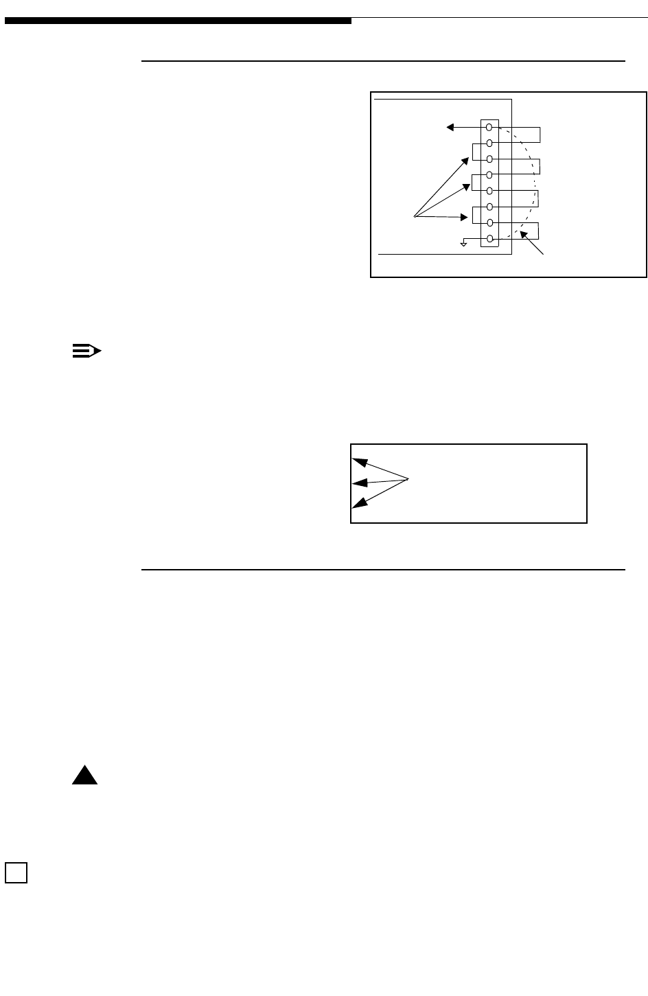
The required fault-off and rf-mute interlocks have been properly wired. These
interlock requirements may vary from site to site.
Ext.
I/O
Bd.
J18
To detector
Circuit
External Interlock jumpers
installed on-site.
Customer Interlock #1
Customer Interlock #2
Customer Interlock #3
Customer Interlock #4
1
2
3
4
5
6
7
8
These connections
are permanent
on PC board. Interlock Bypass jumpe
r
If these 3 interlocks are
not used, a single jumpe
r
from J18-3 to J18-8 is
recommended
12/24/07 888-2685-001 2-9
WARNING: Disconnect primary power prior to servicing.
Section 2 Installation Verification &
Ranger Commissioning Manual
2.8 3 Port Patch Panel Connection Confirmation
IMPORTANT:
If no patch panel or motorized switch is to be installed in the transmitter RF out-
put line, or if the patch panel does not have status switches, then a jumper must
be placed on the External I/O board from J14-3 (RF_SW_A_STAT) to J14-1
(ground).
NOTE:
Refer to the Ranger External I/O Connections schematic 843-5560-105 for the
following connections: (S1 = Antenna position / S2 = Test Load position)
Connect one side of S1A and S2A on the patch panel to J18-1 and the other side to
J18-2 on the External I/O Board in the transmitter. See External I/O Schematic 843-
5549-141, sheet 20, for External interlock connections. This is the transmitter external
interlock input and will shut the transmitter off if the U-Link is removed during
operation. A closed contact between J18-1 and J18-2 is required for the transmitter to
operate. Jumpers must also be placed in the other 3 External Interlock positions, J18-3
to J18-4, J18-5 to J18-6 and J18-7 to J18-8 or one jumper from J18-3 to J18-8.
! CAUTION:
ALWAYS SHUT THE TRANSMITTER OFF BEFORE REMOVING THE U-LINK
TO PREVENT POSSIBLE DAMAGE TO THE CONTACTS.
If the RF Mute interlock connections are not going to be used (and they are
normally not used for patch panels), connect a jumper from J18-9 to J18-12.
If the patch panel has status switches then connect S1B and S2B to the RF switch
status inputs on J14 of the External I/O Board in the transmitter. This allows the
GUI to display the position of the patch panel and will cause a transmitter mute if
neither of these connections are pulled low. These connections include:
• S1B and S2B commons connect to J14-1 (ground)
• S1B (antenna position) connects to J14-3
• S2B (test load position) connects to J14-4
NOTE:
If the patch panel does not have status switches then a jumper must be placed
between J14-1 (ground) and J14-3 (RF_SW_A_STAT) on the External I/O board.
The transmitter will be muted without this connection.

2-10 888-2685-001 12/24/07
WARNING: Disconnect primary power prior to servicing.
Section 2 Installation Verification & Ranger Commissioning Manual
2.9 Motorized RF Switch Connections (if equipped)
IMPORTANT:
If no patch panel or motorized RF switch is to be installed in the transmitter RF
output line, or if the RF switch does not have status switches, then a jumper must
be placed on the External I/O board from J14-3 (RF_SW_A_STAT) to J14-1
(ground).
NOTE:
Refer to the Ranger External I/O Connections schematic 843-5560-105 for the
following connections: (S1 = Antenna position / S2 = Test Load position)
The RF_SW_SEL_OUT at J15-9 on the External I/O board is connected to the
select input on the switch. This output is a TTL open collector, active low, momentary
signal meant to cause a switch to the opposite position. The RF switch should then latch
in that position until pulsed again.
One side of S1A and S2A (interlock switches on the rf switch) is connected to J18-9
and the other side to J18-10 on the External I/O Board in the transmitter. See
diagram 843-5560-105 and/or 843-5549-141 sheet 20, for RF Mute interlock
connections. This is one of the transmitter rf mute interlock inputs and will mute the
transmitter while the switch changes position. Another jumper must be connected
between J18-11 & J18-12 to operate the transmitter.
If the patch panel has status switches then S1B and S2B are connected to the RF
switch status inputs on J14 of the External I/O Board in the transmitter. This
allows the GUI to display the position of the patch panel and will cause a transmitter
mute if neither of these connections are pulled low. These connections include:
• S1B and S2B commons connect to J14-1 (ground)
• S1B (antenna position) connects to J14-3
• S2B (test load position) connects to J14-4
NOTE:
If the patch panel does not have status switches then a jumper must be placed
between J14-1 (ground) and J14-3 (RF_SW_A_STAT) on the External I/O board.
The transmitter will be muted without this connection.
Confirm that the jumpers in the External I/O board for all unused External
Interlocks are installed. See "2.7.1 External Interlocks" on page 2-8 for information
on connections. If no external interlocks are used, connect J18-1 to J18-8.
12/24/07 888-2685-001 2-11
WARNING: Disconnect primary power prior to servicing.
Section 2 Installation Verification &
Ranger Commissioning Manual
Verify that the patch panel or RF switch has been installed and the proper
jumpers and interlocks are in place. These may vary from site to site.
2.10 PA and PS Module Installation
! WARNING:
THE PA MODULES AND POWER SUPPLIES ARE LARGE AND RELATIVELY HEAVY,
WEIGHING APPROXIMATELY 17KG. CARE SHOULD BE TAKEN TO AVOID PER-
SONAL INJURY AND/OR DAMAGE TO THE MODULES. PROPER LIFTING TECH-
NIQUES SHOULD ALWAYS BE USED WHEN HANDLING THE MODULES.
The power supply module is installed at the bottom of the cabinet and secured
with two screws. The breaker on the front of the power supply should be set to
OFF.
The PA module(s) are installed and fully seated into the front of the transmitter
cabinet.
NOTE:
For the CZ1000F, the PA Modules should be placed into the same slot in which
they were tested at the factory. Each module has a serial number tag. This serial
number is recorded on the factory test data sheet along with the appropriate slot
number. Placing the module in a different slot will not cause any harm to the
transmitter but will require more time for module phasing.
! WARNING:
THE RANGER PA MODULES ARE DESIGNED TO HANDLE VERY HIGH TEMPERA-
TURES AND MAY BE EXTREMELY HOT, UP TO 90O F (50O C) ABOVE ROOM TEM-
PERATURE. DO NOT TOUCH THE MODULES WITH BARE HANDS AFTER THE
TRANSMITTER HAS BEEN RUNNING, ESPECIALLY IN HIGH AMBIENT TEMPERA-
TURE ENVIRONMENTS. SPECIAL GLOVES HAVE BEEN PROVIDED IN THE REAR
OF THE CABINET OR CAN BE OBTAINED FROM HARRIS, PART #0990006483 OR
GRAINGER ITEM #4JF36.
2-12 888-2685-001 12/24/07
WARNING: Disconnect primary power prior to servicing.
Section 2 Installation Verification & Ranger Commissioning Manual
2.11 Initial Turn-On
Read and understand the entire initial turn-on procedure before starting. Detailed use of
all GUI screens is given in Section 3 Operation/Alignments.
Shut off the control circuit breaker CB1 and the PS Module breaker (both located
on the bottom front of the transmitter).
Apply primary power to the transmitter at the ac mains disconnect. Be ready to
quickly disconnect the power if necessary.
Turn on the Control circuit breaker, CB1. This should power up the LVPS and bring
up the GUI display. It may be necessary to turn on the LVPS switch (letter “C” in Figure
2-1 on page 2-2). It is located in the back of the transmitter at the top of the controller
assembly.
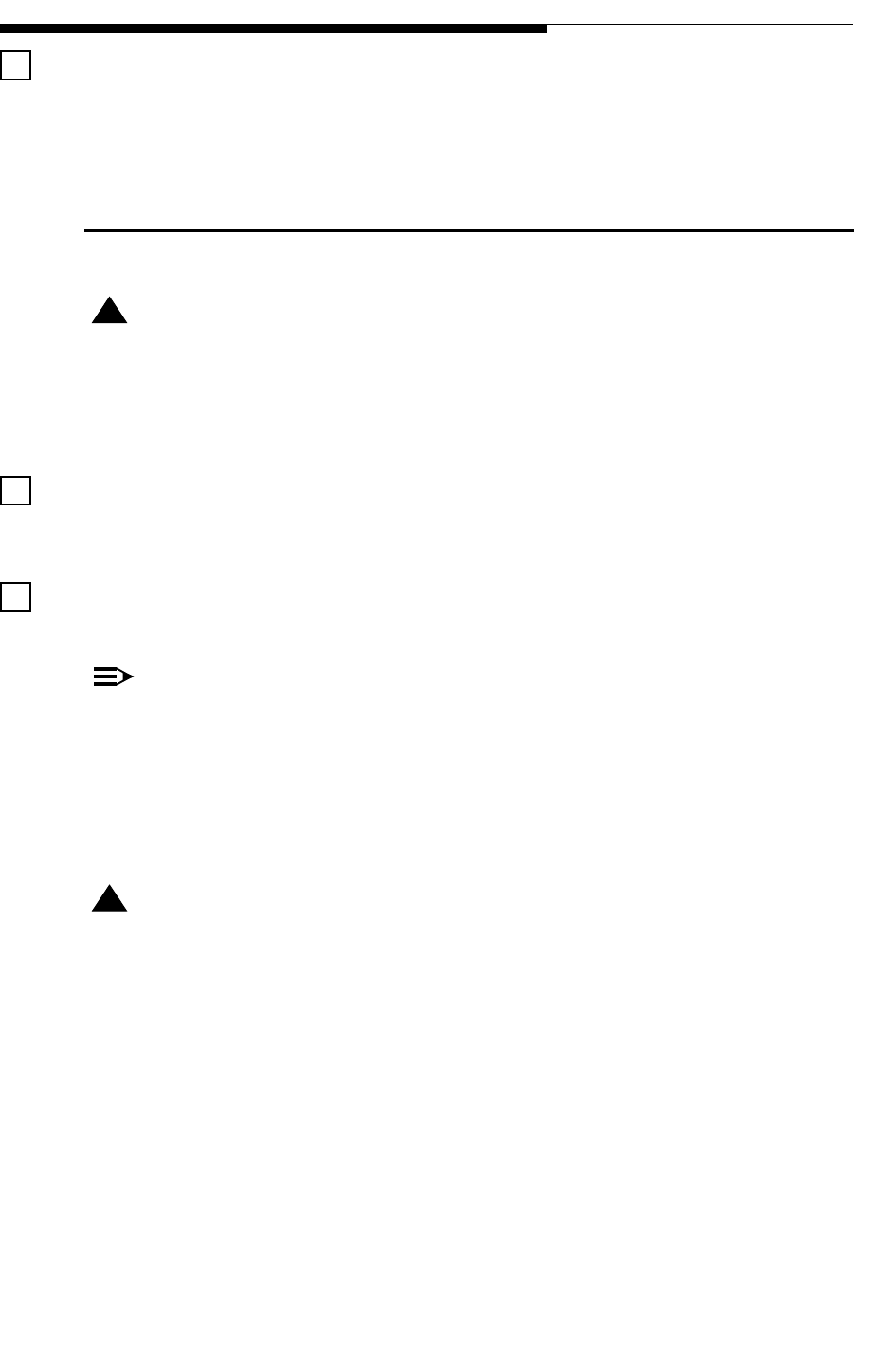
The GUI display should show the Home (default) screen shown in Figure 2-4. Try using
the touchscreen buttons on the right side of the GUI display (not the hardware buttons
to the right of the GUI). If they do not seem to be working or only work when pressed
outside the button graphic, then go to “5.7 Touch Screen Calibration” on page 3-20
before continuing. If the buttons are working then proceed on to the next step.
Figure 2-4 Home Page
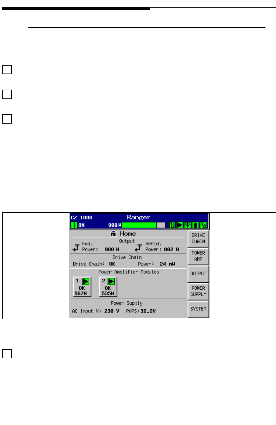
Check the Low Voltage power supplies and AC Mains voltage. Press the POWER
SUPPLY button to access the PS fault and metering screen. Check for +15, -15 and +7.5
volts on LV PSU, with the BUS voltage slightly lower. There should be NO red
indications or faults present. If a fault is present, find the picture of the screen with the
fault in Section 3 for more information.
12/24/07 888-2685-001 2-13
WARNING: Disconnect primary power prior to servicing.
Section 2 Installation Verification &
Ranger Commissioning Manual
Figure 2-5 Power Supply Metering
NOTE:
The PAPS (Power Amplifier Power Supply) readings should be zero and
will be shown as OFF. The PAPS is only active after the transmitter ON
button is pressed. Do not press the transmitter ON button at this time.
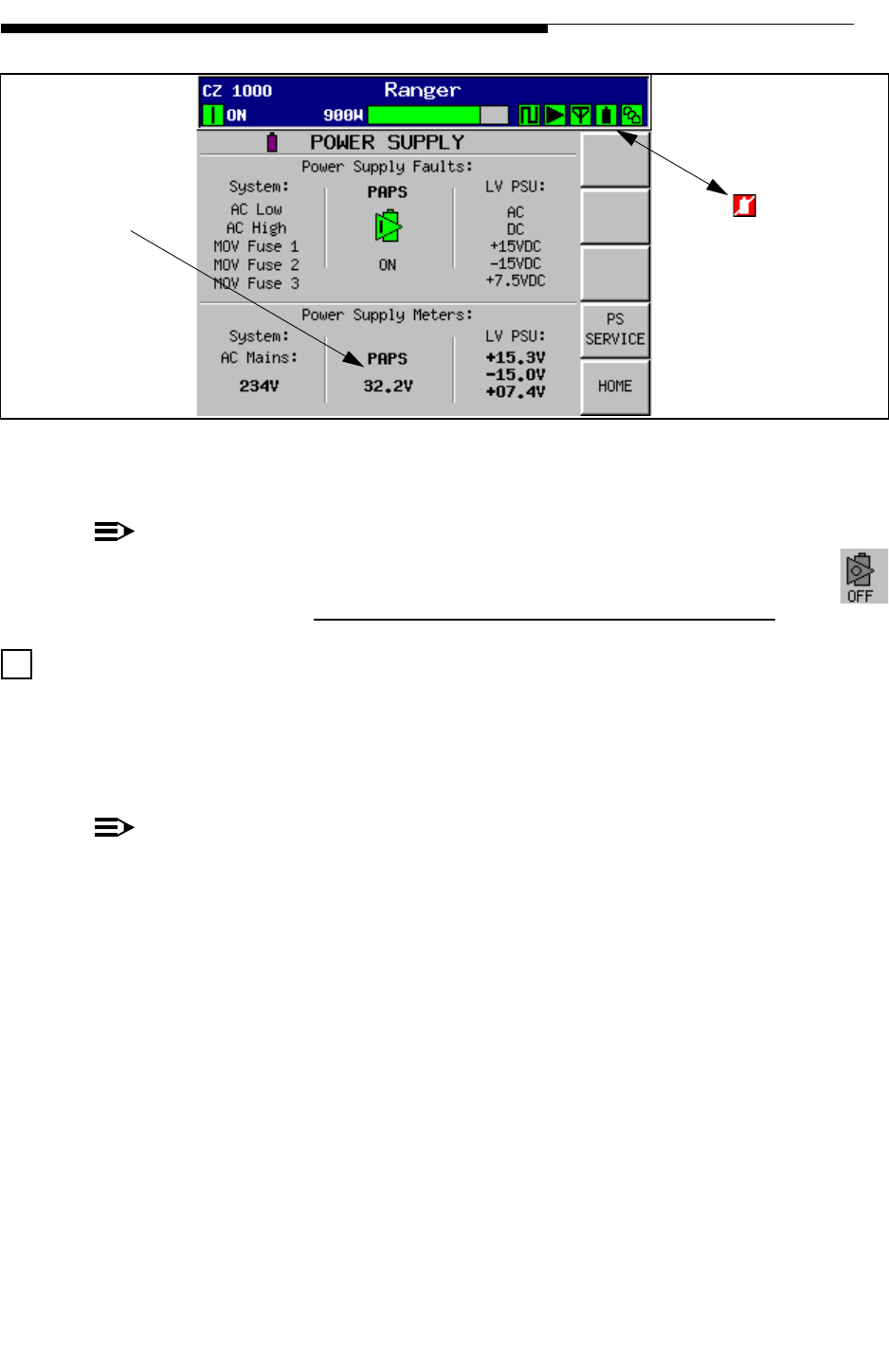
Calibrate the AC Mains Reading. Check your ac mains voltage at the disconnect box.
Next press the PS SERVICE button shown in Figure 2-5. This will take you to the
screen in Figure 2-6. Use the +/- buttons at the bottom of the screen to set the AC Mains
voltage to the same as your measured ac voltage. This is a critical adjustment as this
reading is used for the AC low and high fault thresholds.
NOTE:
This calibration should always be done with the transmitter shut off. Adjustment
can cause various power supply faults to appear momentarily including PS Mute.
PA PS: Reading
will be zero at
this time. Any Power Supply
faults would cause
this icon to turn red
2-14 888-2685-001 12/24/07
WARNING: Disconnect primary power prior to servicing.
Section 2 Installation Verification & Ranger Commissioning Manual
Figure 2-6 PS Service Screen
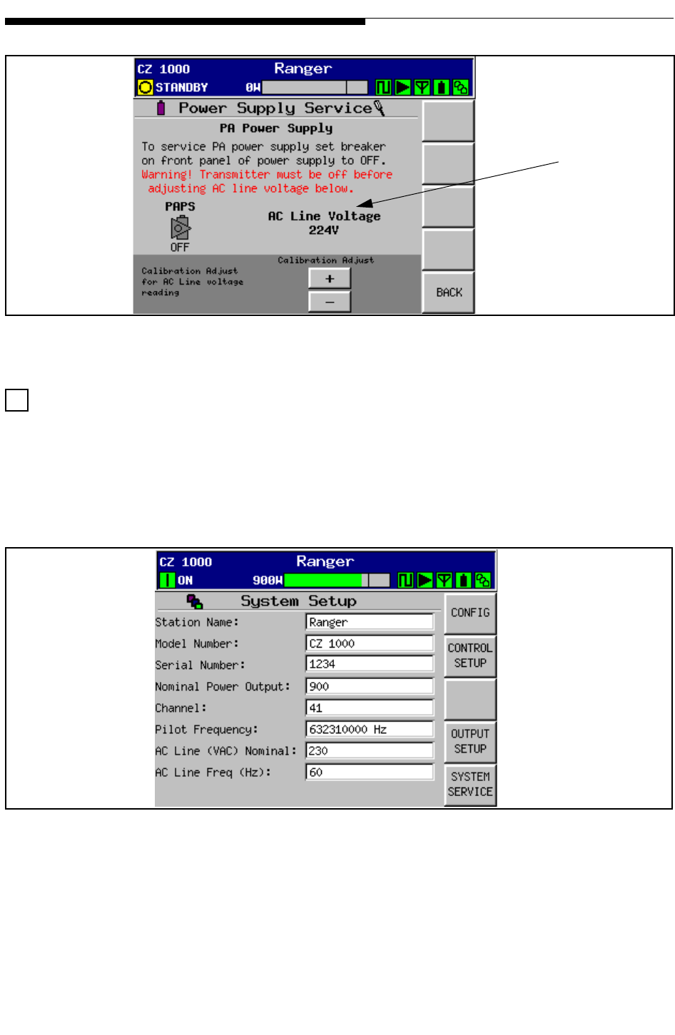
Customize the transmitter System Setup. Press the SYSTEM button then enter the
default password - 1895. Then press SYSTEM SERVICE and SYSTEM SETUP to
access the screen shown in Figure 2-7. The System Setup screen displays the settings
for station name, model number, nominal output power, etc. Touch the screen at each
field to enter the data pertinent to the site. For more information on this screen see
"3.9.3.1 System Setup" on page 3-27.
Figure 2-7 System Setup Screen
This adjustment
will only need t
o
be done during
installation or in
the event the
MOV board or t
he
PS Monitor boa
rd
is changed.

12/24/07 888-2685-001 2-15
WARNING: Disconnect primary power prior to servicing.
Section 2 Installation Verification &
Ranger Commissioning Manual
Press the CONTROL SETUP button in Figure 2-7 to set the Date, Time, LCD
screen contrast and Password on the Control Setup screen, shown in Figure 2-8.
Touch the screen at each field to enter the correct data for Date, time, contrast and
password. There is also a time entry for the LCD screen saver feature.
Figure 2-8 Control Setup Screen
2.11.1 Exciter Setup
The Apex exciters have been factory tested in the transmitter and preset to factory
values. See the Apex Exciter technical manual to modify factory default settings to site
specific parameters.
The exciters are located below the control panel. If there are two exciters Exciter A is
always factory installed as upper unit (located immediately below the transmitter
control panel. The optional exciter B is installed beneath exciter A.
NOTE:
Password must be 4-8
alpha-numeric characters
with no spaces
2-16 888-2685-001 12/24/07
WARNING: Disconnect primary power prior to servicing.
Section 2 Installation Verification & Ranger Commissioning Manual
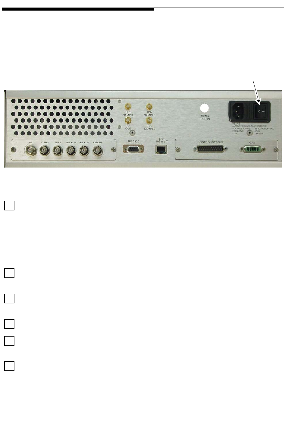
2.11.1.1 Verify Exciter Signal Connections
Most of the input and output connections are at the rear of the exciter, only the RS232
connections are available at the front and rear. Figure 2-9 shows the rear panel
connections.
Figure 2-9 Exciter Inputs and Outputs
ASI #1 and or ASI #2 are connected to the exciter for the low and high priority ASI
transport streams. For best common mode rejection, this cable shield should be
grounded only at the source end.
The input impedance for each connector is 75 ohms. Belden 8281 or similar high-
quality video cable can be used to deliver this signal to the exciter over a distance of up
to 1000 feet.
ASI OUT is a sample output of the active transport stream. It should not have a cable
connected to it unless specified locally.
ANT (GPS antenna input) connector should not have a cable attached since the GPS
receiver is an option and not present in most Mobile exciters.
10MHZ REF IN (BNC) is optional and normally not used in a Mobile system.
1PPS (1 pulse per second input from the GPS receiver) should have a cable connected
to it that comes from the GPS receiver.
HPF RF SAMPLE IN (SMA) has a cable connected to it that comes from the output of
high power mask filter. It is used by RTAC™ (Real Time Adaptive Correction) to
correct for the linear distortions of the high power filter. Normal input signal range is -
30 dBm to 0 dBm. The input impedance is 50 ohms.
AC Power
Off/On Switch

12/24/07 888-2685-001 2-17
WARNING: Disconnect primary power prior to servicing.
Section 2 Installation Verification &
Ranger Commissioning Manual
PA SAMPLE IN (SMA) should have a cable connected to it that comes from the output
of the transmitter power amplifier, taken before the HPF and after the PA combiner for
transmitters with multiple PAs. It is used by RTAC™ to correct for the nonlinear
distortion caused by the power amplifier. Normal input signal range is -30 dBm to 0
dBm. The input impedance is 50 ohms.
IPA SAMPLE IN (SMA), is not used. There should be no cable connected to this
exciter input.
RF OUT (SMA) should be have a cable connected to it. This is the on-channel RF
signal output from the exciter. The output level is adjustable up to 250 mW average but
is intially adjusted to produce an 80 ALC value on the transmitter GUI display.
EXC/CTRL UHF (25 Pin D) should not have a cable connected to it.
CAN (controller area network) should have a cable connected to it. The connector is a
provision for the exciter to communicate with the transmitter GUI (graphical user
interface) system controller.
LAN 10Base-T should have a cable connected to it. The connector is a provision for
connecting the exciter to a local area network.
RS232 (on front and rear panels of exciter) is a 9 Pin D interface connector and they
should not have cables attached to them. They are used to communicate with various
computer applications. The front and rear panel connections can be programmed and
used independently of each other.
2.11.1.2 AC Power
AC Power is applied through a standard power cord to the connector at the right side of
the rear panel as shown in Figure 2-9. The AC inlet connector also contains the power
switch.
The power supply will automatically select the AC input voltage in two ranges. The two
ranges are 85 to 132 VAC or 170 to 264 VAC
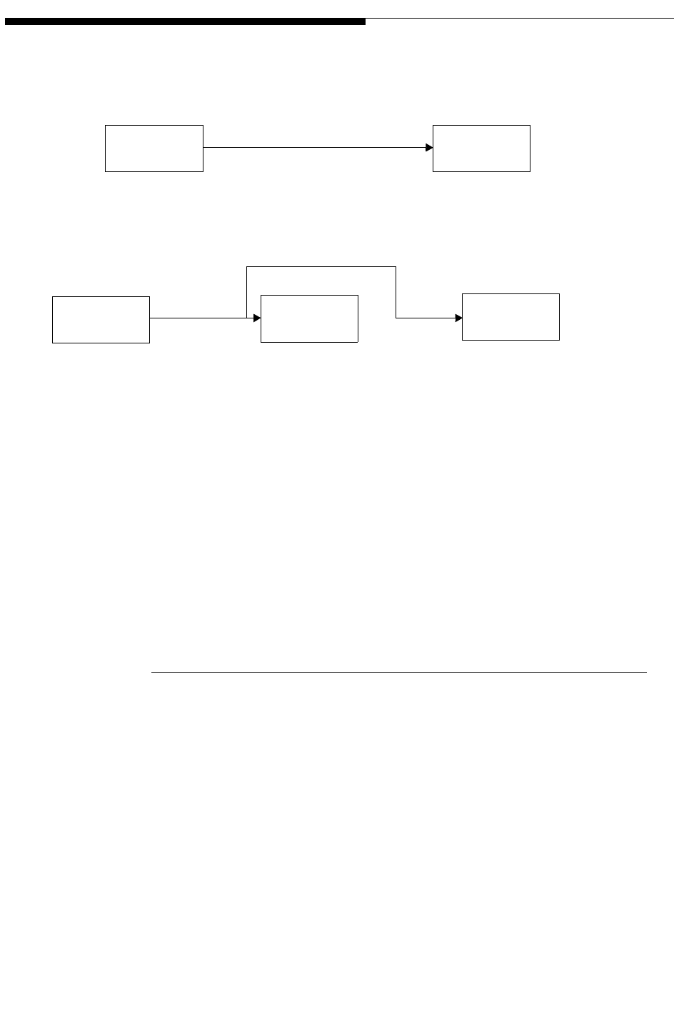
2.11.1.3 Verify Installation of the GPS 1PPS Signal
The GPS (global positioning system) 1PPS (1 pulse per second) signal has a rise time in
the order of a few nanoseconds. It is delivered by a 50 ohm transmission line to the
exciter. Improper termination can cause ringing on the pulse, which, if severe enough
can cause timing errors in the system. The 1PPS signal must be properly distributed and
terminated to avoid the ringing problem.
2-18 888-2685-001 12/24/07
WARNING: Disconnect primary power prior to servicing.
Section 2 Installation Verification & Ranger Commissioning Manual
Figure 2-10 on page 2-18 shows two methods of distributing the 1PPS signal.
Figure 2-10 1PPS Signal Termination Methods.
2.11.1.4 Verify Exciter Configuration
The APEX exciter is configured using the LCD touch screens on the front of the
exciters. The basic functions of these screens are discussed in the Apex Mobile
Technical Manual 888-2604-001. It is necessary to be familiar with these screens in
order to configure the exciter. The following steps are simply a configuration checklist
and should be performed prior to turning on the transmitter PA’s.
GPS 1PPS
Source Apex
Exciter
For a single 1PPS run from source to exciter, set the exciter FPGA modulator
board 1PPS input termination jumper (JP1) to position 1 - 2 (50 ohm termination).
GPS 1PPS
Source
Apex
Exciter #2
Apex
Exciter #1
For a two exciters, the 1PPS signal can be bridged through exciter 1,
1. Keep the tee connector close to exciter 1’s 1PPS connector (within one foot)
position 2 - 3 (high impedance).
to avoid the ringing problem.
3. Set exciter 2’s FPGA modulator board 1PPS input termination jumper (JP!) to
position 1 - 2 (50 ohms).
2. Set exciter 1’s FPGA modulator board 1PPS input termination jumper (JP!) to
Do not position the tee connector more than one foot from exciter 1,
because this will aggravate the ringing problem.
12/24/07 888-2685-001 2-19
WARNING: Disconnect primary power prior to servicing.
Section 2 Installation Verification &
Ranger Commissioning Manual
2.11.1.4.1 Verify Configuration of Setup Screens
NOTE:
The screen menus are given in Italics before the setup values.
Main Screen.
Set exciter RF output power (the display reads average power) Normal value is less
than 120 mW.
Set the two RTAC functions. These are typically set to ADAPT.
Main Screen > Setup > Exciter Setup.
Power Limit is usually set to 250 mW.
Reference, refers to External or Internal GPS use. External is the normal mode. If
used, it requires an external 1PPS input at the rear panel connector.
Verify that the exciter is set to the correct channel.
NOTE:
Diagnostic Setup must be unlocked before the frequency or offsets can be
changed.
Verify that the correct transmitter type has been selected.
If waveguide is used to feed the antenna and group delay precorrection is desired, select
the type and length (in feet) of waveguide. Typically, coaxial line and not waveguide
will be used.
Main Screen > Setup > Display Setup.
Verify the Date and Time.
Enter a new page title, if something other then APEX Exciter is desired. For example a
site name might be entered.
Select the desired Chart selection to allow the operator to view the Main screen
response display at various points along the transmitter system.
Adjust LCD Contrast to allow best viewing in the local conditions. Higher numbers
produce greater contrast, lower numbers produce less contrast.
Main Screen > Setup > Change Password (or Security) Setup.
2-20 888-2685-001 12/24/07
WARNING: Disconnect primary power prior to servicing.
Section 2 Installation Verification & Ranger Commissioning Manual
Change passwords as required to satisfy operational requirements.
Main Screen > Setup > User Setup (Lock or Unlock).
Lock or unlock User Setup to satisfy operational requirements.
Main Screen > Setup > Diagnostic Setup (Lock or Unlock).
Lock or unlock Diagnostic Setup to satisfy operational requirements.
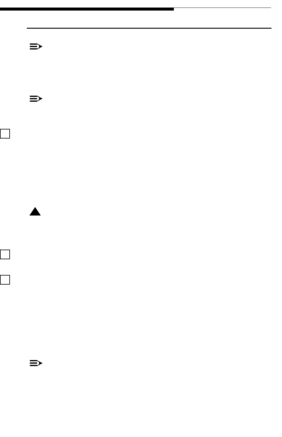
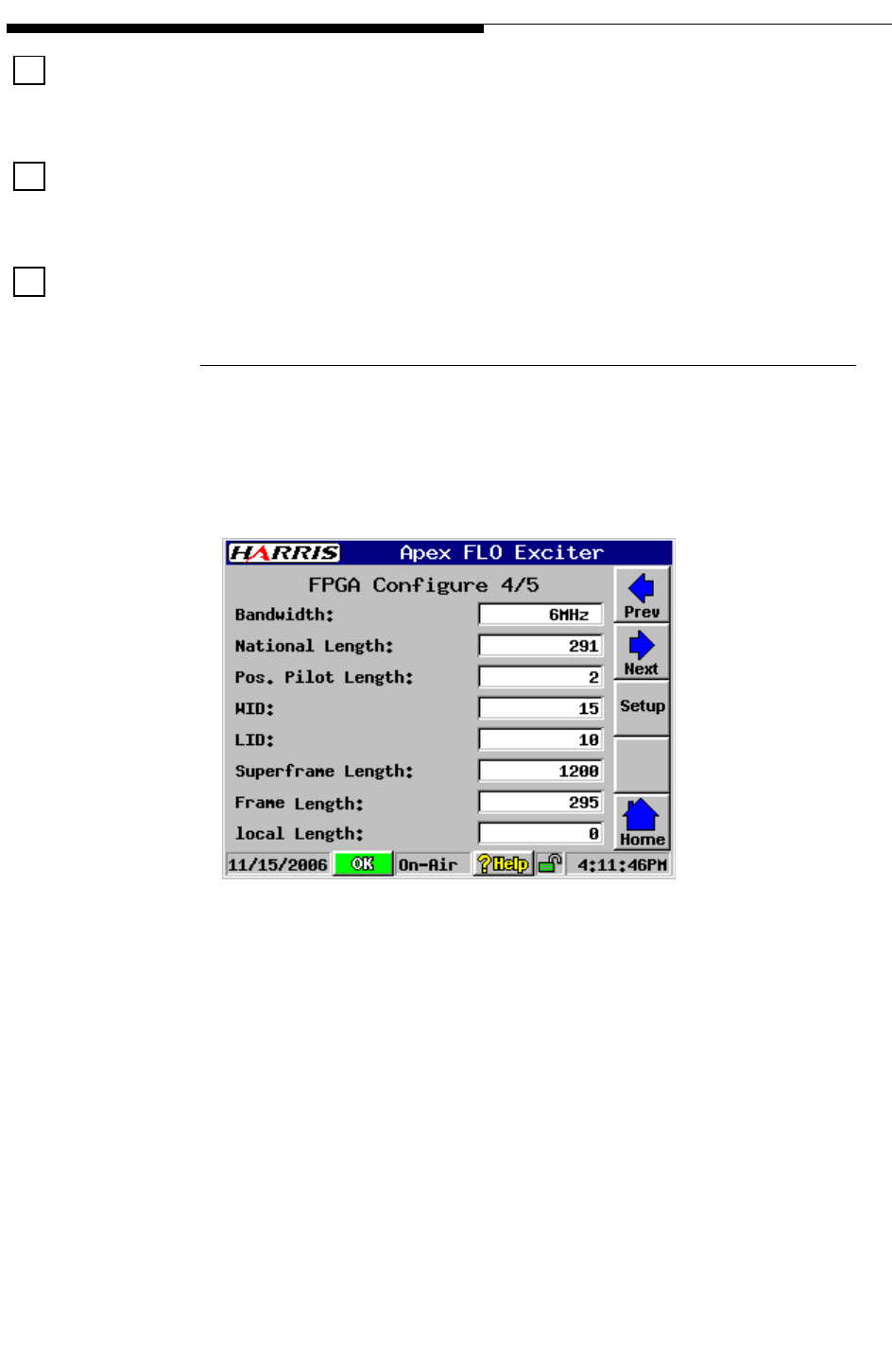
2.11.1.5 Verify Configuration of FPGA Screens
When configuring an exciter for the first time, it is useful to check the setting s in the
FPGA screens. The exciter manual gives detailed information on settings but the values
on FPGA screen 4/5 are especially importatant.Values shown in Figure 2-11 are typical
for 6 MHz operation but may need to be updatedto meet on-site operational
requirements.
Figure 2-11 FPGA Configure 4/5
FPGA Configure 4/5 consists of registers whose values are written immediately to the
FPGA when changed through the GUI.
FPGA re-initialization shall occur automatically after any FPGA Configure 4/5 register is
changed.
The parameters of the FPGA Configure 4/5 screen are as follows.
•Bandwidth: 5MHz / 6MHz / 7MHz / 8MHz.
•National Length: Unsigned Decimal, range dependent on bandwidth:
0-245 5MHz, 0-295 6MHz, 0-345 7MHz, 0-395 8MHz. XXX Define
•Pos. Pilot Length: 2 / 6 / 10 / 14 – not bandwidth dependent. XXX Define
•WID: Unsigned Decimal, range 0-15. XXX Define

12/24/07 888-2685-001 2-21
WARNING: Disconnect primary power prior to servicing.
Section 2 Installation Verification &
Ranger Commissioning Manual
•LID: Unsigned Decimal, range 0-15. XXX Define
•Superframe Length - Display Only
•Frame Length - Display Only
•Local Length - Display Only.
2.11.1.6 Verify Configuration of Status Screens
When configuring an exciter for the first time, it is useful to check certain portions of
the following status screens.
Main Screen > Status > ASI Input.
• This screen should show no faults if both ASI #1 and ASI #2transport
streams are present at the exciter input.
• If either transport stream is present no transport stream fault will appear on
the front panel Transport Stream hardware switch, it will light green. If both
are missing, the front panel Transport Stream and the Digital Processing
hardware switches will show faults (light red)
Main Screen > Status > Adaptive Processing.
• HPF feedback (RF sample from output of high power filter), and Amp
Feedback (RF power amplifier output sample) bargraphs:
• These bargraphs, each of which contain blue (peak power) and yellow
(average power) traces, should be within their active travel ranges if the
feedback signals are within the correct power range (-30 to 0 dBm). If the
signal is out of range, that input will fault.
• ADC OvrRange (analog to digital converter over range) will be Ok if all
feedback signals are within their proper ranges, and will fault if any are too
large.
Main Screen > Status > ASI Input screen will show fault if both transport streams are
missing.
• Main Screen > Status > Digital Processing > FLO FPGA Registers > FPGS
Summary 1/5 > TS Active Indicates the active transport stream (TS1 Active
or TS2) It will show fault if both ASI transport streams are missing.
• Main Screen > Status > Digital Processing > FLO FPGA Registers >
Transport Stream Status Screen 3/5 > TS1 Detect and TS2 Detect indicates
the presence of the transport streams by yes or their absence by no.
• Main Screen > Status > Digital Processing > FLO FPGA Registers > FPGA
Summary 2/5 > SFN MODE should be set to ON at all times.

2-22 888-2685-001 12/24/07
WARNING: Disconnect primary power prior to servicing.
Section 2 Installation Verification & Ranger Commissioning Manual
2.11.1.7 Normal Settings for Diagnostic Screens
The Diagnostics screens offer tests used to diagnose exciter problems. If the diagnostic
selections are left in the wrong states, normal operation of the exciter could be
impaired. The default values for the diagnostics screens can be found in Table 5-1 on
page 10.
The following is a list of the normal states of the more critical diagnostic functions and
the exciter mute.
Status > Adaptive Processing > Diagnostics
• LoopBack: None
• Test Tones: Disabled
Status > IF & RF Processing > Up Converter > Diagnostics
• Output Power AGC: Enabled
Status > IF & RF Processing > Down Converter > Diagnostics
• RF Sample Select: Automatic
• RF Sample AGC: Enabled
Status > System Control > External I/O Board > Diagnostics
• Analog Loopback: Disabled
Setup >Exciter > Exciter Setup screen> Mute soft key.
• The exciter is normally un-muted. Pressing the button will open a sub window which
will have instruction to mute or un-mute the exciter output.
12/24/07 888-2685-001 2-23
WARNING: Disconnect primary power prior to servicing.
Section 2 Installation Verification &
Ranger Commissioning Manual
2.11.2 RF Initial Turn ON
Shut the transmitter OFF. The transmitter should be initially powered into a test load.
Measure the test load impedance prior to application of RF power. The load can be
measured with a network analyzer prior to application of RF. Typical load VSWR
values are < 1.05:1 at the operating channel. If verification of load VSWR is not
possible then proceed with RF turn on at low levels and gradually increase power while
monitoring reflected power levels. If significant reflected power levels are noted then
measurement of the test load will be required.
Set the Exciter power to zero. This can be done using the lower button on the exciter
GUI or the Lower button on the transmitter control panel.
Switch ON the ac breaker on the front of the PA power supply. Monitor the Power
Supply screen shown in Figure 2-5 on page 2-13.
Press the transmitter ON button. Make sure the PA PS reading is close to 32Vdc.
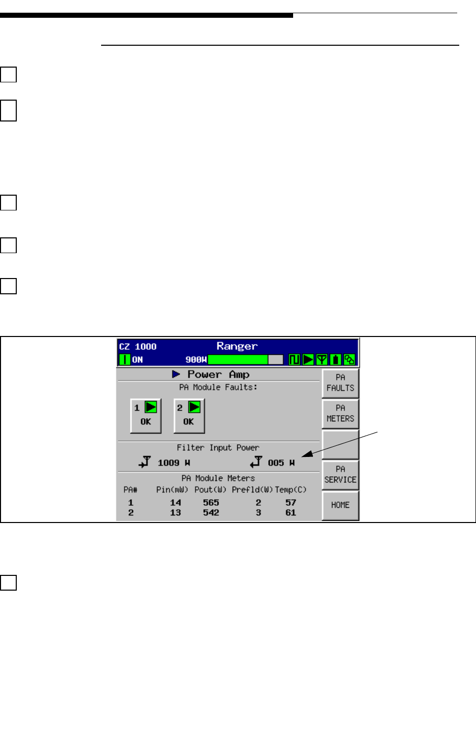
Next, go to the Power Amp screen shown in Figure 2-12.
Figure 2-12 Power Amp Main Menu
Raise the transmitter power (or exciter power) slowly until about 50% nominal and
check the transmitter reflected and PA module reflected powers. The transmitter should
be operating normally with no faults indicated. Any faults should be corrected before
continuing. The power output bargraph on the top of the GUI screens will be yellow
until the power is 80% or more. Verify that the reflected power is under 10 watts.
Reflected Power
should be less
than 10 watts
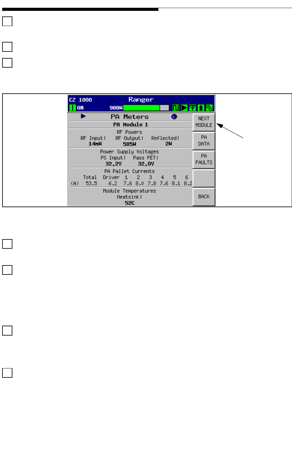
2-24 888-2685-001 12/24/07
WARNING: Disconnect primary power prior to servicing.
Section 2 Installation Verification & Ranger Commissioning Manual
Check the power on the HOME screen (shown in Figure 2-4) to check for excessive
reflected power after the mask filter.
All PAs should show a green (OK) status on the GUI (Power Amp screen).
Monitor the PA Meters screen shown in Figure 2-13. This screen can be accessed by
pressing the PA Meters button on the Power Amp screen in Figure 2-12.
Figure 2-13 PA Meters Screen
Press POWER SUPPLY and verify that all PA power supplies show OK status
(green).
Press OUPUT then OUTPUT METERS. This page shows the forward and reflected
powers for the Cabinet and Total System power (after filters). The VSWR is indicated
as well. Calibration should not be required since all couplers are inside the cabinet and
calibrated as part of the factory testing. If the calibration is not correct as determined by
a digital power meter, refer to "3.7.3 Forward and Reflected Power Calibrations" on
page 3-20.
Slowly bring up the transmitter power to the nominal value, as indicated by the
bar graph. Monitor the cabinet forward and reflected powers, as well as the VSWR
reading. A large VSWR (above 1.1) is indicative of a bad RF connection to the test
load.
Check the PA Module “Gain Balance” on the PA Setup screen (press Power Amp,
PA Service, PA Setup to get to Figure 2-14). This is adjusted at the factory and does not
require re-adjustment as long as the current readings in Figure 2-14 are within 1 amp of
each other. If the readings are more than 1 amp apart then perform the following:
NOTE:
Data for nominal
readings.
See Factory Test
(This button not
used on CZ500F)
Use this button
to check PA
Module #2 on
the CZ1000F
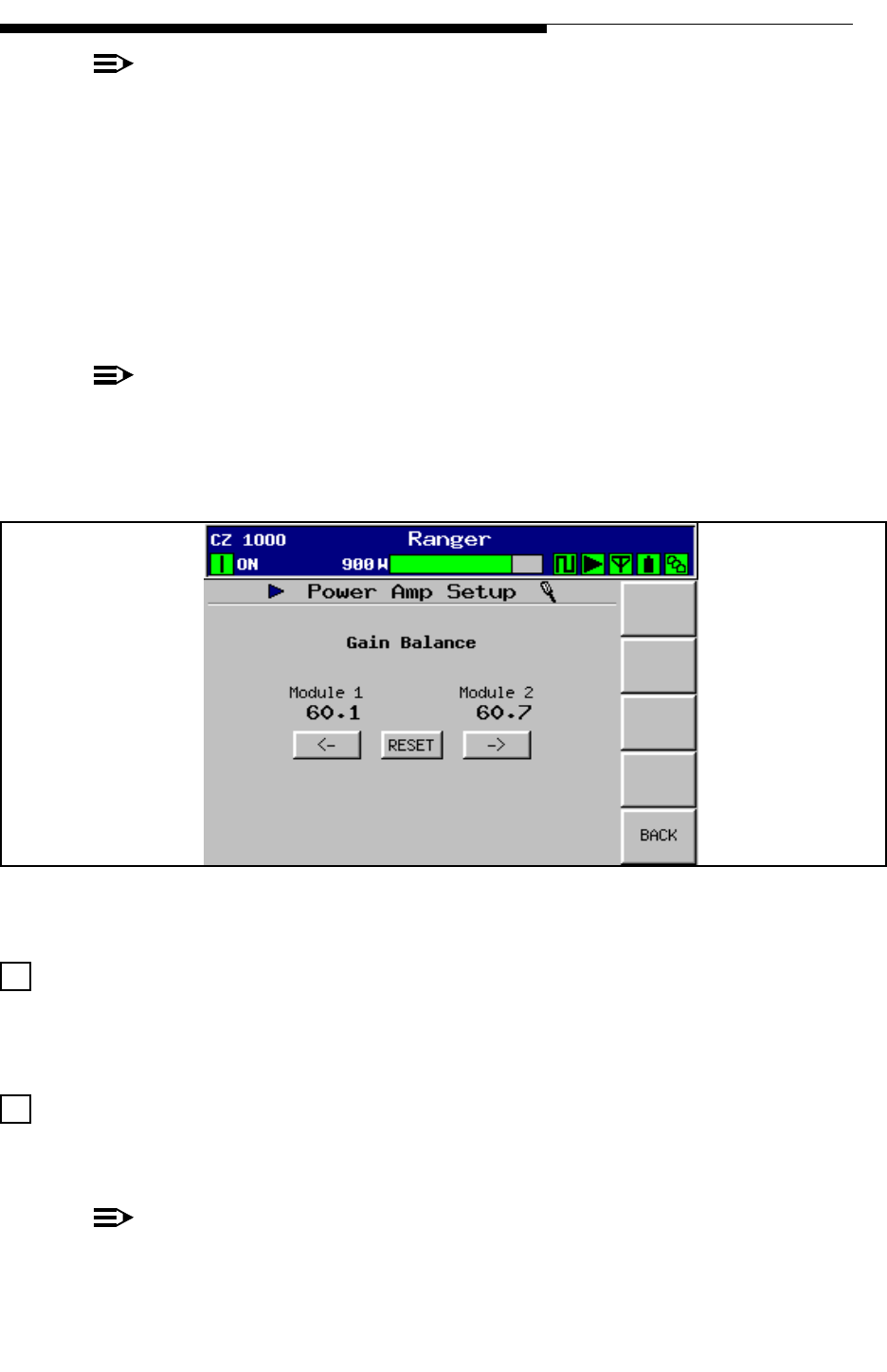
12/24/07 888-2685-001 2-25
WARNING: Disconnect primary power prior to servicing.
Section 2 Installation Verification &
Ranger Commissioning Manual
NOTE:
This adjustment should only be done at full power and after the module tempera-
tures have had time to stabilize. PA Module phasing should always be optimized
after finishing this procedure.
STEP 1 Press the RESET button. This allows the adjustment to always start from
a common point.
STEP 2 Use the Left and/or Right arrow buttons until the numbers match. There
will be some bounce in the readings, but they should be as close as
possible and no more than 1 amp apart.
NOTE:
This adjustment is not to be used to decrease the PA module combiner reject
power. In some cases this adjustment may actually increase the PA module com-
biner reject power by a few watts.
Figure 2-14 PA Setup Screen
Check the PA Module Phasing (press Output, Output Service). The Reject Load
Power (relative) reading should be less than 0030 with the gain button set to low (at full
rated power). If not, refer to "3.7.2 Module Phasing Procedure" on page 3-18, before
proceeding, then return here to finish the installation.
Make sure the PA and HPF correctors are turned ON on the APEX exciter and
check transmitter performance. Refer to the APEX exciter manual 888-2604-001 for
settings.
NOTE:
Section 4 RF Testing outlines commissioning RF measurements.

2-26 888-2685-001 12/24/07
WARNING: Disconnect primary power prior to servicing.
Section 2 Installation Verification & Ranger Commissioning Manual
Press transmitter off button to turn off RF output power.
Measure the antenna and transmission line impedance prior to application of RF
power to the antenna system. The transmission line and antenna can be measured with
a network analyzer prior to application of RF.
! CAUTION:
MEASURE THE AMOUNT OF RF POWER ON THE ANTENNA TRANSMISSION LINE
PRIOR TO MEASUREMENT WITH A NETWORK ANALYZER. IN SOME INSTANCES
THE RF ENERGY FROM NEARBY STATIONS MAY BE PRESENT ON THE
TRANSMISSION LINE IN AMOUNTS LARGE ENOUGH TO DAMAGE THE NETWORK
ANALYZER. IN CASES LIKE THIS MEASUREMENTS MAY BE TAKEN WITH
AMPLIFIERS USED TO AMPLIFY THE NETWORK ANALYZER SIGNAL SO THAT IT IS
LARGE ENOUGH TO OVERCOME THE RFI PRESENT ON THE SYSTEM TO BE
MEASURED.
Typical antenna system VSWR values are < 1.2:1 at the operating channel. If
verification of antenna system VSWR is not possible then proceed with RF turn on at
low levels and gradually increase power while monitoring reflected power levels. If
significant reflected power levels are noted then measurement of the system will be
required.
2.12 Parallel Remote Control Connections
External Parallel remote control units can interface at the External I/O Board in the rear
of the cabinet. J13 through J17 are for remote Control, Status and Analog readings. The
connectors are organized as follows:
•J13 and J14 - Remote Transmitter Control Functions
•J15 and J16 - Remote Status Outputs
•J17 - Remote Analog Metering Outputs
NOTE:
The forward slash ( / ) in front of a signal name means active low. The signal /
INPUT 1 for example is activated by momentarily bringing that input low. Signal
names without the forward slash are considered active high. This convention is
used throughout the schematics.
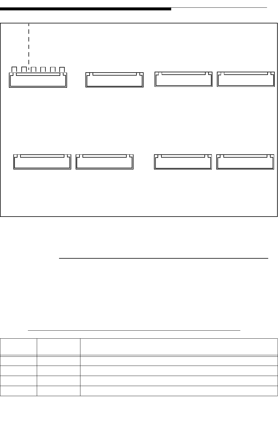
12/24/07 888-2685-001 2-27
WARNING: Disconnect primary power prior to servicing.
Section 2 Installation Verification &
Ranger Commissioning Manual
Figure 2-15 External I/O Connector Locator
2.12.1 Transmitter Control Functions, J13 and J14
All control inputs use opto-isolators for surge protection. The opto-isolators are
powered by an internal +5Vdc from an isolation protection circuit, U54. All transmitter
control functions (except Remote RF Mute) are momentary ground switching and
require the remote control equipment to sink at least 15mA to activate the function. The
Pinouts of J13 and J14 are listed in Table 2-1.
Table 2-1 J13 & J14, External I/O Board, Remote Control Connectors
Connector Schematic
Label Function
J13-1 GND Ground
J13-2 /INPUT 1 REMOTE_ON
J13-3 /INPUT 2 REMOTE_OFF
J13-4 /INPUT 3 REMOTE_RAISE
GND A
/INPUT 1
/INPUT 2
/INPUT 3
/INPUT 4
GND
GND
/INPUT 5*
/INPUT 6*
/INPUT 7
/INPUT 8*
GND
GND
INPUT 9
/INPUT 10
/INPUT 11
/INPUT 12*
GND
GND
/INPUT 13*
/INPUT 14*
/INPUT 15*
/INPUT 16*
GND
GND B
+5VDC ISOLATED
OUTPUT 1
OUTPUT 2
OUTPUT 3
OUTPUT 4
OUTPUT 5
OUTPUT 6
OUTPUT 7
OUTPUT 8
+VDC EXT SUPPLY
GND
GND B
+5VDC ISOLATED
OUTPUT 9
OUTPUT 10
OUTPUT 11
OUTPUT 12
OUTPUT 13
OUTPUT 14
OUTPUT 15
OUTPUT 16
+VDC EXT SUPPLY
GND
GND A
VOUTA
VOUT B
VOUT C
VOUT D
GND
GND
VOUT E
VOUT F
VOUT G
VOUT H
GND
SYSTEM
FAULT OFF
INTERLOCK
RF SWITCH
INTERLOCK
(MUTE)
11
112
12
12
12 1
112
12 1
112
12 1
NOT USED FOR RANGER
J11
J12 J15 J16
J13
J14
J17
J18
1-2
3-4
5-6
7-8
9-10
11-12
EXTERNAL I/O BOARD
REMOTE CONNECTOR
LOCATIONS AND PINOUTS
NOTE:
Left half of PC
Board not shown
* Not Used

2-28 888-2685-001 12/24/07
WARNING: Disconnect primary power prior to servicing.
Section 2 Installation Verification & Ranger Commissioning Manual
2.13 Remote Status Outputs, J15 & J16
All of the remote status outputs are open collector and will sink 100mA at up to +24Vdc
to provide an indication status is active. The pull up supply voltage for the status
J13-5 /INPUT 4 REMOTE LOWER
J13-6 GND Ground
J13-7 GND Ground
J13-8 /INPUT 5 Spare
J13-9 /INPUT 6 Spare‘
J13-10 /INPUT 7 REMOTE_RF MUTE_ON- Transmitter RF output is muted as long as this input
is held low. (High = Un-mute)
J13-11 /INPUT 8 Spare
J13-12 GND Ground
J14-1 GND Ground
J14-2 /INPUT 9 REMOTE_RF_SW A/B_SELECT
J14-3 /INPUT 10 RF_SW_A_STAT (from 3 port U-Link panel or motorized RF switch, Antenna
position status) Input held low while in antenna position
J14-4 /INPUT 11 RF_SW_B_STAT (from 3 port U-Link panel or motorized RF switch, Load
Position status) Input held low while in test load position
J14-5 /INPUT 12 Not Used
J14-6 GND Ground
J14-7 GND Ground
J14-8 /INPUT 13 Spare
J14-9 /INPUT 14 Spare
J14-10 /INPUT 15 Spare
J14-11 /INPUT 16 Spare
J14-12 GND Ground
Table 2-1 J13 & J14, External I/O Board, Remote Control Connectors
Connector Schematic
Label Function

12/24/07 888-2685-001 2-29
WARNING: Disconnect primary power prior to servicing.
Section 2 Installation Verification &
Ranger Commissioning Manual
indications can be supplied via J15 & J16 or can be supplied by an external voltage
source. The status output connections are listed in Table 2-2.
Table 2-2 J15 & J16, External I/O Board, Remote Status Outputs
Connector Schematic Label Status Output
J16-1 GNDB Isolated Ground
J16-2 +5VDC_ISOLATED Output - install jumper to J16-11 to use internal supply for status pull
ups. Otherwise an external supply will have to be connected to J16-11.
J16-3 /OUTPUT 1 Off/On Status
J16-4 /OUTPUT 2 Life Support Status
J16-5 /OUTPUT 3 RF Mute Status
J16-6 /OUTPUT 4 External Interlock Status
J16-7 /OUTPUT 5 Drive Chain Fault Status
J16-8 /OUTPUT 6 Power Amp Fault Status
J16-9 /OUTPUT 7 Output Fault Status
J16-10 /OUTPUT 8 Power Supply Fault Status
J16-11 +VDC_EXT_SUPPLY Input For External Pull Up Supply Voltage
J16-12 GNDB Isolated Ground
J15-1 GNDB Isolated Ground
J15-2 +5VDC_ISOLATED Output - install jumper to J15-11 to use internal supply for status pull
ups. Otherwise an external supply will have to be connected to J15-11.
J15-3 /OUTPUT 9 Control Fault Status
J15-4 /OUTPUT 10 Cooling Fault Status
J15-5 /OUTPUT 11 Summary Fault Status
J15-6 /OUTPUT 12 Remote Control Enabled Status
J15-7 /OUTPUT 13 Transmitter Off Status
J15-8 /OUTPUT 14 RF Switch A/B Status
J15-9 /OUTPUT 15 RF_SW_SEL_OUT (to motorized RF switch)
J15-10 /OUTPUT 16 VSWR Fault/Foldback Active Status
J15-11 +VDC_EXT_SUPPLY Input For External Pull Up Supply Voltage
J15-12 GNDB Isolated Ground

2-30 888-2685-001 12/24/07
WARNING: Disconnect primary power prior to servicing.
Section 2 Installation Verification & Ranger Commissioning Manual
2.13.1 Remote Power Metering, J17
Each analog metering output will provide 0 - 4.096Vdc output into a 400 ohm load
(where 3Vdc = Nominal). The connections for J17 are listed in Table 2-3.
Table 2-3 J17, External I/O Board, Remote Power Metering
Connection Schematic Label Metered Parameter
J17-1 GND Ground
J17-2 VOUTA Total Forward Power (After Filter)
J17-3 VOUTB Total Reflected Power (After Filter)
J17-4 VOUTC Forward Power Cabinet #1 (Before Filter)
J17-5 VOUTD Reflected Power Cabinet #1 (Before Filter)
J17-6 GND Ground
J17-7 GND Ground
J17-8 VOUTE Spare
J17-9 VOUTF Spare
J17-10 VOUTG Spare
J17-11 VOUTH Spare
J17-12 GND Ground
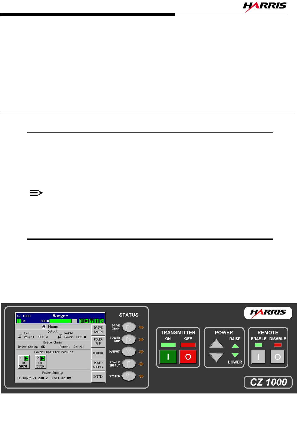
12/24/07 888-2685-001 3-1
WARNING: Disconnect primary power prior to servicing.
Ranger Commissioning Manual
Section 3
Operation and
Adjustments 3
3.1 Introduction
This section gives detailed operation and adjustment information for the Ranger™
Series Solid-State UHF Series transmitter. It contains all information necessary to make
any operational changes or adjustments which appears on any of the Graphical User
interface (GUI) Touchscreen display screens.
NOTE:
Operation and adjustment of the Apex exciter using FLOR Technology is covered
in a separate manual which came with the transmitter.
3.2 Transmitter Control Panel
The front panel user interface is a 1/4 VGA, LCD touchscreen display. The touchscreen
display uses software buttons to monitor the transmitter. Hardware buttons for the
primary transmitter functions such as ON/OFF, RAISE/LOWER and Remote Enable/
Disable are provided on the overlay panel next to the display as shown in Figure 3-1.
Figure 3-1 Transmitter Control Panel
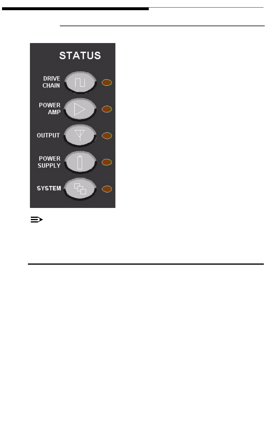
3-2 888-2685-001 12/24/07
WARNING: Disconnect primary power prior to servicing.
Ranger Commissioning Manual
Section 3 Operation and Adjustments
3.2.1 Main Menu “Hardware” Buttons
Just to the right of the touchscreen, there are 5 hardware
buttons which are part of the front panel overlay.
Located next to each button is a Status LED which
illuminates green under normal, no fault conditions.
These buttons provide quick access to each of the 5
main transmitter groups, namely:
a. Drive Chain
b. Power Amp
c. Output
d. Power Supply
e. System
The Status LED next to the button will turn red if there
is a warning or fault condition in that section of the
transmitter. It will be green if the sub-system is normal.
This provides quick access to the required and relevant
diagnostics information, without having to be familiar
with a menu structure.
NOTE:
To differentiate these buttons from the ones which show up on the LCD display,
these will be referred to as “Hardware” buttons in the manual text.
3.3 Graphical User Interface (GUI)
The GUI (“Gooey”) was designed to provide an intuitive interface into the transmitter
control system. Once you know what information is available, finding the information
you want is simply a matter of following the screens to the desired section of the
transmitter. Menu Trees of all available screens is given at the end of this section, see
"3.10 GUI Menu Structures" on page 3-32.
For the most part, all navigation through the GUI screens is done via the touchscreen
and softkeys (software buttons). The exceptions are the 5 hardware buttons mentioned
above. The touchscreen display is also divided into an active display area, which will
change with each screen, and the global areas which are present on all screens.
SYSTEM
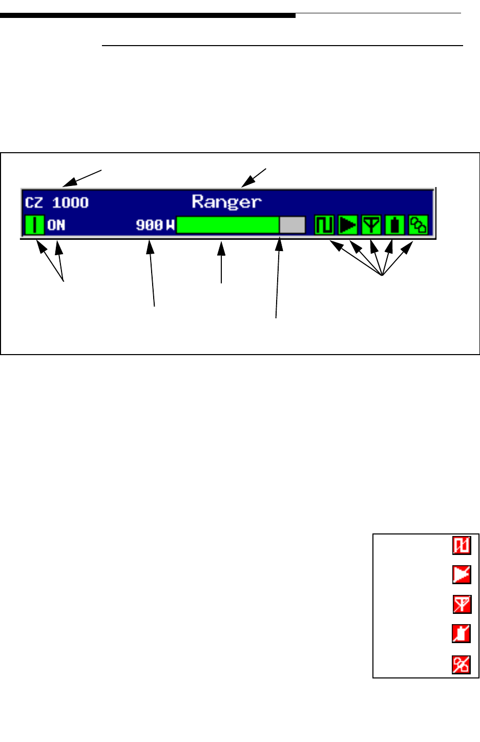
12/24/07 888-2685-001 3-3
WARNING: Disconnect primary power prior to servicing.
Section 3 Operation and Adjustments
Ranger Commissioning Manual
3.3.1 Global Status and Navigation
The top 2 lines of the touchscreen display (shown in Figure 3-2) are considered global
because they show up on all screens. The top line gives the transmitter model number
and the station name and/or location which is entered by the customer in the System
Setup screen, in Figure 3-22, with a maximum of 24 characters including spaces.
Figure 3-2 Global Touchscreen Display Sections
The second line of the display has operational and status information including:
a. ON, Standby, OFF or Fault OFF as well as status information.
b. Transmitter Forward power output reading (after Filter) in numerical format.
c. Transmitter Forward power output reading in a Bargraph format. The 100% mark
is based on the nominal power level or TPO (Transmitter Power Output) entered
into the System Setup screen in Figure 3-22. The bargraph will also turn yellow if
the power level is more than 20% higher or lower than the nominal 100% level.
d. Main Menu Symbols which are basically status for the 5
main transmitter sections. If illuminated red, as shown to
the right, that section of the transmitter has one or more
faults. These status indicators correspond to the 5 hardware
buttons to the right of the display.
The icons on the top bar in Figure 3-2 should be all green under
normal (no fault) operating conditions. A red symbol or status
indication should be investigated by the station engineer.
Station Name and/or Location
Transmitter Model Number
Operation and Fault
Status Transmitter System
Power Output
Power Bargraph Main Menu Symbols
with Color Status
100% Mark - Based on Nominal TPO
setting in System Setup screen
Drive Chain
Power Amp
Output
Power Supply
System
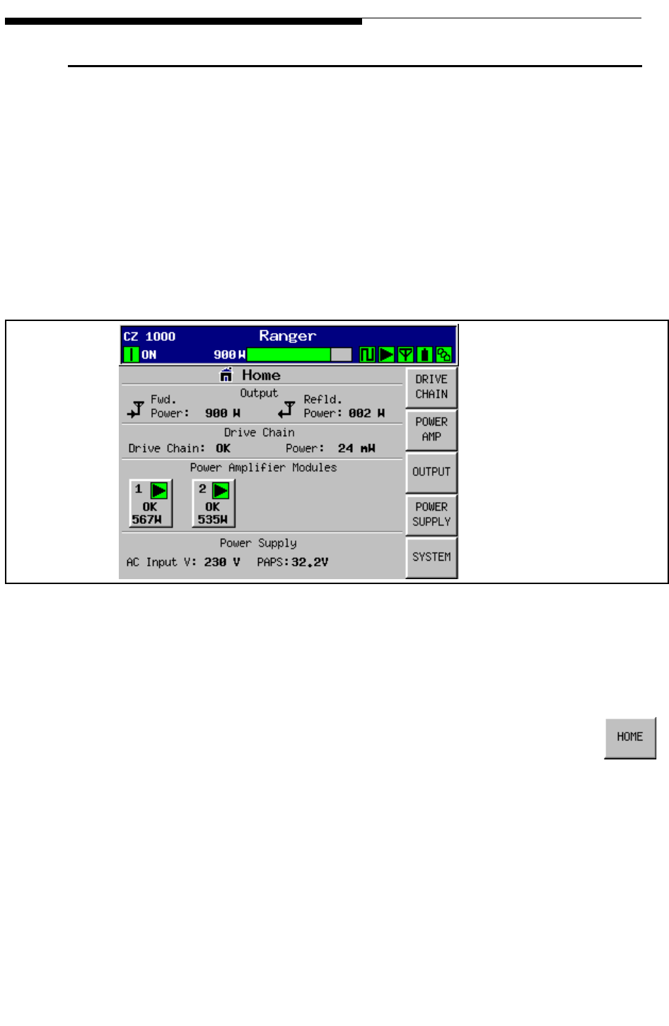
3-4 888-2685-001 12/24/07
WARNING: Disconnect primary power prior to servicing.
Ranger Commissioning Manual
Section 3 Operation and Adjustments
3.4 GUI Home Page
The HOME screen shown in Figure 3-3 is the primary operator screen and the default
screen after boot up. The HOME screen contains the most important general operator
information such as:
a. System Forward and Reflected power
b. Drive chain status and power level
c. Individual Power Amplifier PA Module status and power level
d. AC line voltage and PA power supply voltage.
Figure 3-3 Home Screen
It also has the global status and operation information at the top of the screen which
shows the transmitter status and if there are any faults present.
The HOME button is a software button located in the lower right-hand
corner of all 5 main menu screens for quick navigation to the HOME screen
in Figure 3-3. This screen can only be accessed using the software buttons
on the touchscreen (there is no hardware HOME button). The quickest way to access
the HOME screen is to press any of the 5 hardware buttons to the right of the display as
there is a HOME button on each of those main menu screens.
There are always five touchscreen navigation buttons on the right side of the display.
These are different on almost every screen and, with the exception of the HOME screen,
do not relate to the hardware buttons on the front panel just to the right of the display.
To Figure 3-4 on page 3-5
To Figure 3-6 on page 3-7
To Figure 3-12 on page 3-1
5
To Figure 3-16 on page 3-2
1
To Figure 3-18 on page 3-2
3
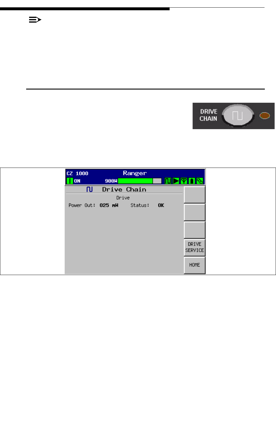
12/24/07 888-2685-001 3-5
WARNING: Disconnect primary power prior to servicing.
Section 3 Operation and Adjustments
Ranger Commissioning Manual
NOTE:
To simplify the discussion of GUI navigation, the following will navigate and
describe all of the screens under each of the 5 main menu buttons located to the
right of the touchscreen display (and on the right side of the GUI Home screen).
3.5 Drive Chain Main Menu
If you press the Drive Chain button on the control panel
overlay, or the Drive Chain button on the HOME screen,
it will take you to the screen shown in Figure 3-4. The
Drive Chain screen is simply a dedicated exciter power
monitoring screen. The power reading comes from RF
Splitter/Coupler (A12) and is detected on the RF Monitor Board.
Figure 3-4 Drive Chain Screen
To Figure 3-5
To Figure 3-3
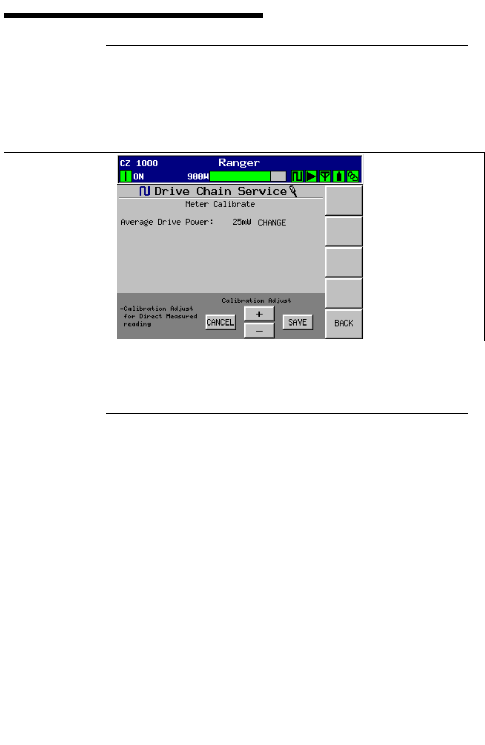
3-6 888-2685-001 12/24/07
WARNING: Disconnect primary power prior to servicing.
Ranger Commissioning Manual
Section 3 Operation and Adjustments
3.5.1 Drive Service
When the “Drive Service” button in Figure 3-4 is pressed, it will bring up the screen
shown in Figure 3-5. This screen allows for calibration of the exciter power reading on
the Drive Chain screen in Figure 3-4. This reading should be set to match the measured
exciter output.
Figure 3-5 Drive Service Screen
3.5.2 Drive Meter Calibration
To calibrate the reading Drive Chain power output reading in Figure 3-4, go to the
Drive Chain Service screen shown above.
STEP 1 Measure the exciter power output with a digital power meter. This
should be done with the exciter running at nominal TPO.
STEP 2 Press the (+) or (-) buttons to adjust the reading on the Drive Service
screen until it matches the measured value.
STEP 3 Press SAVE to calibrate the GUI reading or CANCEL to abort the
changes.
To Figure 3-4
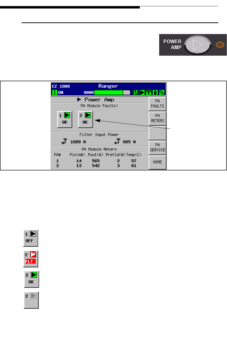
12/24/07 888-2685-001 3-7
WARNING: Disconnect primary power prior to servicing.
Section 3 Operation and Adjustments
Ranger Commissioning Manual
3.6 Power Amp Main Menu
If you press the Power Amp button on the control panel
overlay, or the Power Amp button on the HOME screen,
it will take you to the screen shown in Figure 3-6. The
Power Amp Menu Tree is shown in Figure 3-32 on page
3-33.
Figure 3-6 Power Amplifier Screen
This screen shows the Forward and Reflected power for the PA Modules and the total
output power before the mask filter. Each of the amplifier select buttons in the middle of
the screen are for navigation to the PA Faults screen. These buttons are also status
indicators with 3 different modes:
Button showing PA Module has been turned OFF.
Button showing PA Module #2 has a Fault. Press the button to go to PA Faults.
Button showing PA Module 2 ON with no faults.
Button showing PA Module removed from transmitter.
To Figure 3-7
To Figure 3-8
To PA Faults screen,
Figure 3-7
To Figure 3-10
To Figure 3-3
Module 2 button
will be grayed out
for CZ500F.
NOTE:
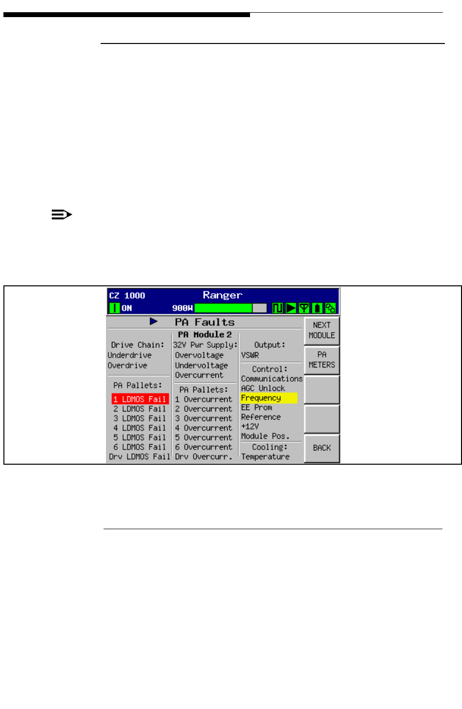
3-8 888-2685-001 12/24/07
WARNING: Disconnect primary power prior to servicing.
Ranger Commissioning Manual
Section 3 Operation and Adjustments
3.6.1 PA Faults
This screen is basically a list of all of the faults monitored in each PA Module.
• An active fault will be highlighted in RED
• A warning condition will be highlighted in YELLOW.
The PA Faults screen in Figure 3-7, shows that PA Module #2 has 1 LDMOS fault and a
Frequency warning. The NEXT MODULE button is to toggle between the fault
information on each module and will be inactive for the CZ500F. Table 3-1 is a listing of all
of the faults shown on this screen, including the fault limit and action taken by the module.
NOTE:
The only part of the module which is field repairable is the individual PA pallets
(the six in the center of the module). There is a special pallet replacement kit
available. For more information refer to Section 5, Replacements Procedures.
Figure 3-7 PA Faults Screen (PA Module 2 Selected)
3.6.1.1 Module 3 strike Routine
Under certain critical fault conditions, the PA module will try to shut off (Strike) and
then re-initialize to try and clear the fault condition. If the fault is still present after the
module turns back on it will shut off (Strike) again. If the fault is still present after a 3rd
strike or returns within several seconds after the 3rd strike, the fault is latched and the
module is shut off. The module may be turned on again by pressing the transmitter ON
button. If the fault is still present, the module will simply repeat the 3 strike routine
again. Table 3-1 tells which faults activate the 3 strike routine.
To Figure 3-8
To Figure 3-6

12/24/07 888-2685-001 3-9
WARNING: Disconnect primary power prior to servicing.
Section 3 Operation and Adjustments
Ranger Commissioning Manual
Table 3-1 PA Module Faults
Fault Fault limit Action Taken
Frequency Channel frequency or frequency band reported by module does
not match system settings. Affects Module Calibration. Warning
EEPROM Error was detected writing to EEPROM on Module Controller Warning
Reference +5V reference voltage is not within tolerance Warning
+12V Fault +12V not in tolerance Warning
Com Fail Module is not talking on CAN bus. Module might continue
operating. Re-seat module to see if problem clears. Warning
Pallet Over-
current Amplifier pallet current has exceeded 12 amps. Most likely
blown FET Module shuts off
Driver Pallet
Over-current Amplifier pallet current has exceeded 12 amps. Most likely
blown FET. Note that this reading also includes current for Phase
and gain driver transistors
Module shuts off
LDMOS Fail FET failure based on pallet current levels. Fault is set for each
push-pull pair. Fault is set when pallet current is less than 60% of
highest pallet current in module. If pallet current is below 40%,
the whole pallet is considered bad which is 2 LDMOS failures.
For pallet replacement procedure refer to Section 5.
Up to 3 LDMOS faults
on a single module =
warning. 4 LDMOS
faults = OFF
Over Voltage +32V source has exceeded 33V Module 3 strike
Under Voltage +32V source is below 30 V Module 3 strike
Over Current Total current on +32V line has exceeded 75A Module 3 strike
Over Temp Module temperature has exceeded 95oCModule 3 strike
High VSWR Internal reflected RF too high. About 200W of reflected power.
Most likely a bad cable or circulator Module 3 strike
Over Drive Input RF is too high. Trip point set to 1.9dB above nominal or
approximately 23mW Module 3 strike
Low Input Input RF is too LOW. Module continues to run Warning
AGC Unlock Module AGC circuit is unable to maintain constant gain. Module
gain is 46dB. This fault means the DAC number for the I or Q
Vector reading on the PA Data screen has reached “0” or “4095”
and the module gain is still not 46dB
Module 3 strike
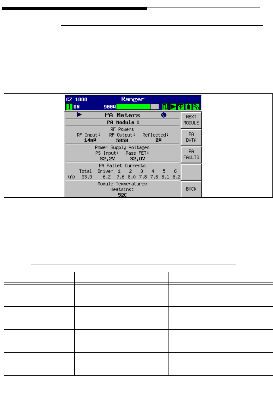
3-10 888-2685-001 12/24/07
WARNING: Disconnect primary power prior to servicing.
Ranger Commissioning Manual
Section 3 Operation and Adjustments
3.6.2 PA Meters
This screen is accessed by pressing the “PA Meters” button in Figure 3-6 or Figure 3-7.
A complete set of PA Meter readings is given in the Factory Test Data. The Factory Test
Data readings are taken at rated power unless otherwise specified by the customer. Any
reading out of tolerance will be reported as a fault to the control system and show up on
the PA Faults screen in Figure 3-7.
Figure 3-8 PA Metering Screen
The following table gives typical readings (at 600W output) and fault limits for each
reading. See factory test data for more accurate readings for your transmitter and
frequency.
Table 3-2 PA Module Typical Readings and Fault limits
Reading Typical Reading Fault Limit
RF Input 15mW 0 = underdrive / 23mW = Overdrive
RF Output 600W none
Reflected Less than 10 watts Fault = 200W
Power Supply Voltage 32Vdc Under V = 30V / Over V = 33V
Total Module Current 55 - 65 amps 75 amps
Driver Pallet Current 6 - 7 amps 12 amps
PA Pallet Currents 8 - 10 amps each 12 amps
Heatsink Temperature 60 - 65oC (affected by ambient) 90oC
*Current readings will vary with frequency and power output.
To Figure 3-9
To Figure 3-7
To Figure 3-7
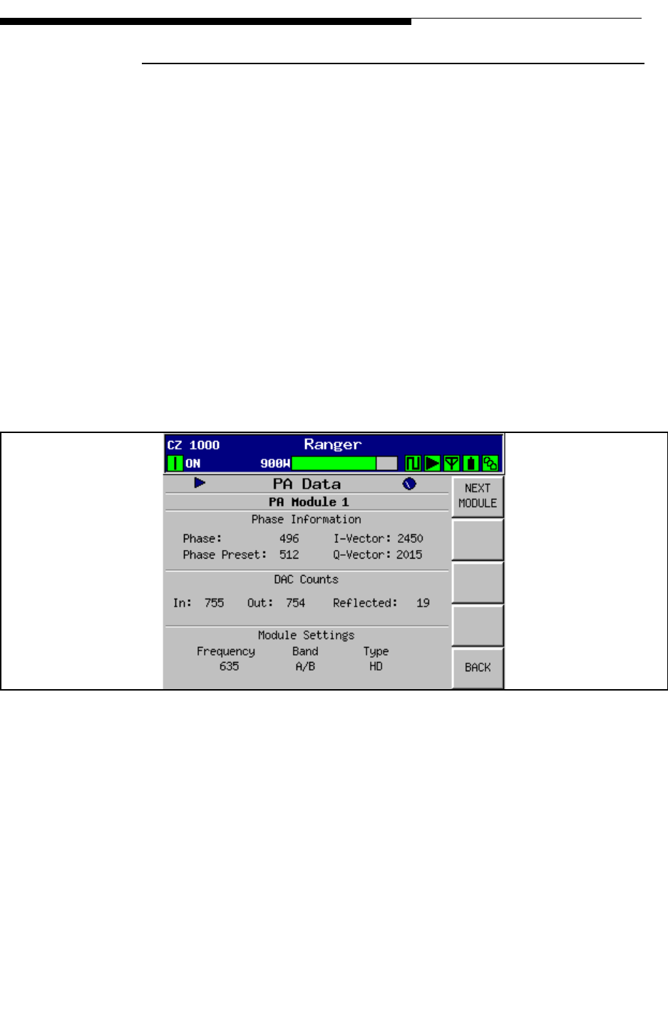
12/24/07 888-2685-001 3-11
WARNING: Disconnect primary power prior to servicing.
Section 3 Operation and Adjustments
Ranger Commissioning Manual
3.6.3 PA Data
The PA Data screen in Figure 3-9 is accessed from the PA Meters screen in Figure 3-8.
It contains vital information about the operation of the PA module. The readings are
ADC or DAC counts in either 10 bit (0 - 1023) or 12 bit (0 - 4095). For detailed theory
on the PA Module refer to Section 4, Theory of Operation.
a. Phase - This is an analog voltage from the Backplane Interface board which is
used to adjust the insertion phase of the module. In the CZ1000F this is used to
adjust the phase of PA Module 2 to match that of PA Module 1 (and to optimize
the PA Module combiner). The module controller converts the analog voltage
from the Backplane Interface board to a digital 10 bit word from 1 - 1023 with the
ideal being 512 or centered in the range. PA Module 1 receives a fixed voltage
which places it approximately in the center of the range (it is not critical), while
module 2 receives a variable voltage via R7 on the Backplane Interface to allow
for module phasing. This input controls the I and Q Vector outputs to the Phase
and Gain board in the module.
Figure 3-9 PA Data Screen
b. I and Q Vectors -These are 12 bit DAC outputs from the module controller to the
Phase and Gain board in the module with a range of 0 - 4095. The phase voltage
from the Backplane Interface board adjusts these readings in opposite directions
to set the insertion phase through the module but they are also used to adjust the
module gain as part of the module AGC. These readings are considered OK as
long as they are not at the limit of the range. If either of these numbers are 0 or
4095, the PA Faults screen will register an AGC Unlock fault.
c. Phase Preset - This is a fixed setting inside the module and should read approxi-
mately 512.

3-12 888-2685-001 12/24/07
WARNING: Disconnect primary power prior to servicing.
Ranger Commissioning Manual
Section 3 Operation and Adjustments
d. DAC Counts - These are 10 bit (0-1023) ADC samples of the detected RF input
and Forward and Reflected power output.
• IN - Is a sample of the detected RF drive input to the module. Nominal input
for 400W output is 15mW. This number is usually in the 800 range for full
rated output. The input overdrive fault is detected from this reading and is
triggered when the DAC reading is approximately 1.9dB above nominal or
• Out - This is a sample of the detected forward power sample from the
directional coupler on the module output. This is used for metering and as
the sample for the module AGC. This number is forced by the AGC to track
the IN reading, thereby keeping the module gain at 46dB.
• Reflected - This is the detected sample from the reflected coupler on the
module output. It is used for metering of reflected power or VSWR. Can be
used as a relative reading to detected changes in the module output.
e. Module Settings - These are status readings from the module to the transmitter
controller. The FREQUENCY and the BAND are set via the Channel number
entered into the System Setup screen shown in Figure 3-22. These are simply
read backs to verify that the module is setup properly. If not set properly, module
calibration could be affected. All Ranger modules should read HD (High power
Diamond) under TYPE.
The Bands are:
• Band A/B - Channels 14 - 41
• Band C/D - Channels 42 - 69
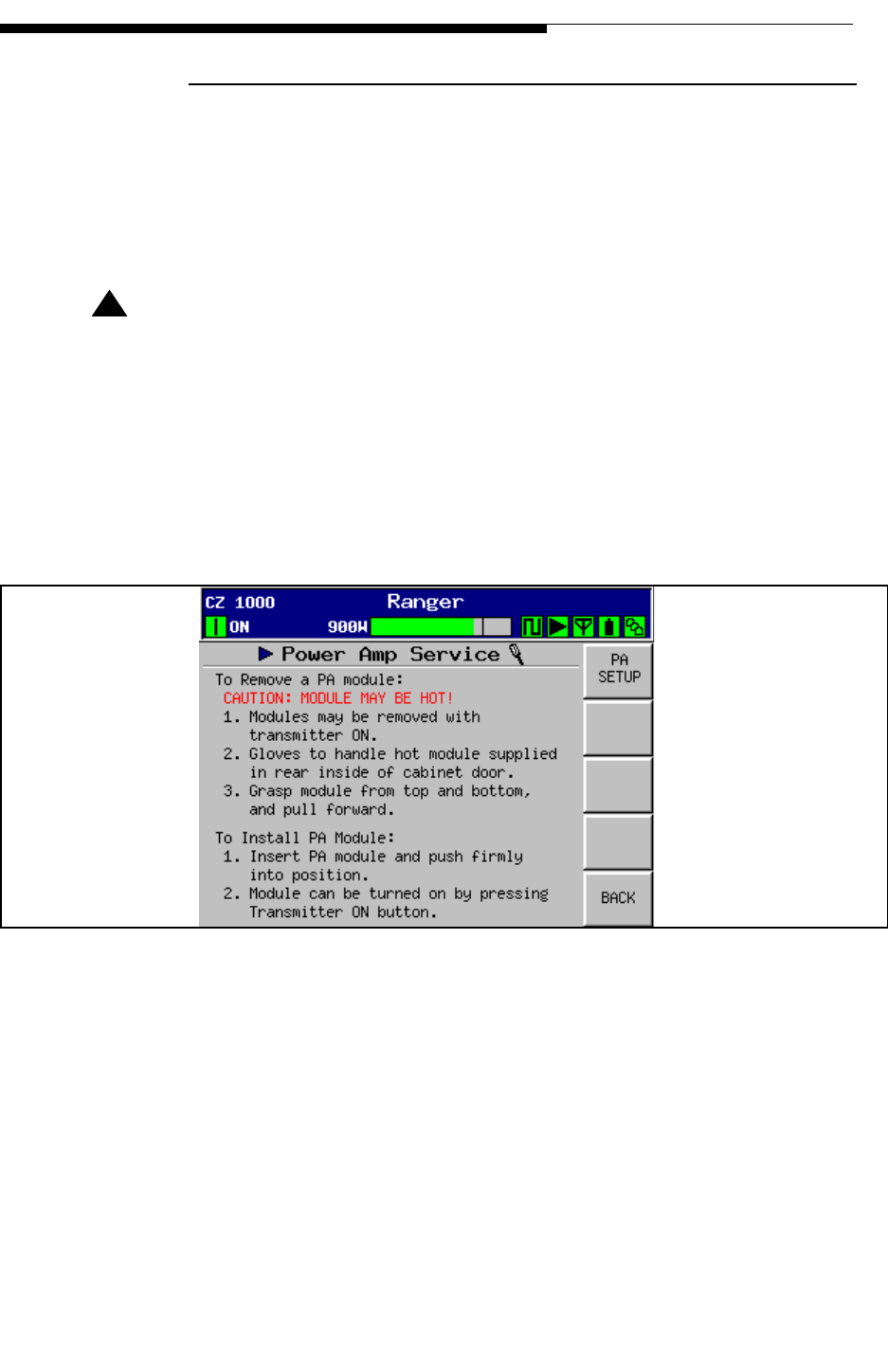
12/24/07 888-2685-001 3-13
WARNING: Disconnect primary power prior to servicing.
Section 3 Operation and Adjustments
Ranger Commissioning Manual
3.6.4 PA Service
This screen is accessed by pressing the “PA Service” button in Figure 3-6. This is a help
screen for removing and replacing PA Modules. Be sure to have a place ready to set the
module down after it is removed. It also provides access to the PA Setup screen in
which is used in the CZ1000F to balance the gain of the 2 modules.
! WARNING:
HOT SURFACE
THE RANGER PA MODULES ARE DESIGNED TO HANDLE VERY HIGH TEM-
PERATURES AND MAY BE EXTREMELY HOT, UP TO 90O F (50O C) ABOVE
ROOM TEMPERATURE. DO NOT TOUCH THE MODULES WITH BARE HANDS
AFTER THE TRANSMITTER HAS BEEN RUNNING, ESPECIALLY IN HIGH
AMBIENT TEMPERATURE ENVIRONMENTS. SPECIAL GLOVES HAVE BEEN
PROVIDED IN THE REAR OF THE CABINET OR CAN BE OBTAINED FROM
HARRIS, PART #0990006483 OR GRAINGER ITEM #4JF36.
Figure 3-10 PA Service Screen
To Figure 3-11
To Figure 3-6
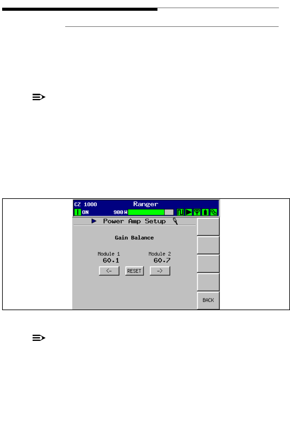
3-14 888-2685-001 12/24/07
WARNING: Disconnect primary power prior to servicing.
Ranger Commissioning Manual
Section 3 Operation and Adjustments
3.6.4.1 PA Setup (Gain Balance)
This screen is accessed by pressing the PA Setup button in Figure 3-10. Its sole purpose
is to balance the gain of the 2 PA modules in the CZ1000F transmitter. The goal is to
match the 2 module gain readings. Adjustment is only required if the module current
readings in Figure 3-11 are more than 1 amp apart. This procedure will have to be done
if a module is changed. The adjustment procedure is simple.
NOTE:
This adjustment should only be done at full power and after the module tempera-
tures have had time to stabilize. PA Module phasing should always be optimized
after finishing this procedure.
STEP 1 Press the RESET button. This allows the adjustment to always start from
a common point.
STEP 2 Use the Left and/or Right arrow buttons until the numbers match. There
will be some bounce in the readings, but they should be as close as
possible and no more than 1 amp apart.
Figure 3-11 PA Setup Screen
NOTE:
This adjustment is not to be used to decrease the PA module combiner reject
power. In some cases this adjustment may actually increase the PA module com-
biner reject power by a few watts.
It may be necessary to adjust the PA module phasing via the pot on the Module
Backplane board. For PA Module phasing see "3.7.2 Module Phasing Procedure" on
page 3-18.
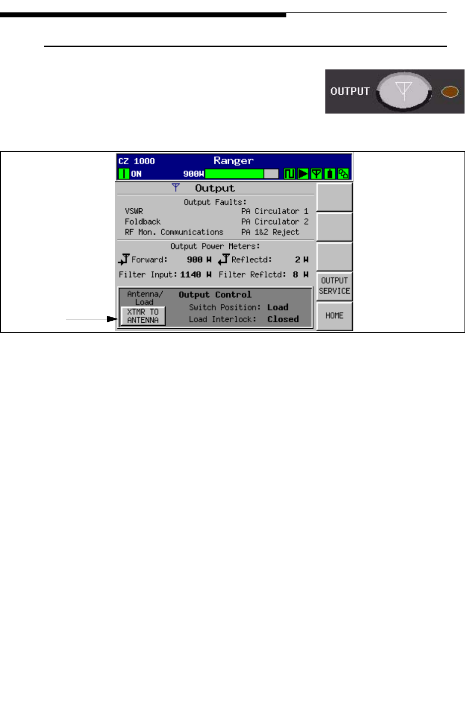
12/24/07 888-2685-001 3-15
WARNING: Disconnect primary power prior to servicing.
Section 3 Operation and Adjustments
Ranger Commissioning Manual
3.7 Output Main Menu
If you press the Output button on the control panel
overlay, or the Output button on the HOME screen, it
will take you to the screen shown in Figure 3-12. The
Output Menu Tree is shown in Figure 3-31 on page 3-33.
Figure 3-12 Output Screen
This screen is broken into 3 main areas:
a. Output Faults - This panel lists the 6 possible output screen faults. A fault would
cause one or more to be highlighted in red while a warning condition would high-
light yellow.
1. VSWR - VSWR has exceeded fault threshold of 1.9:1
2. Foldback - VSWR has exceeded foldback threshold of 1.4:1 (VSWR fold-
back is accomplished automatically by reducing the exciter power).
3. RF Monitor Communications - A warning condition stating that the RF
Monitor board is not communicating over the CAN bus to the Main Con-
troller.
4. PA Circulator 1 or PA Circulator 2- the power to the circulator reject load
has exceeded 400W. The RF Monitor board is calibrated to give a 3 Vdc
detected sample when the output from the reject attenuator is 40mW (40dB
below 400W).
5. PA 1&2 Reject - the power to the combiner reject load has exceeded 400W.
The RF Monitor board is calibrated to give a 3 Vdc detected sample when
the output from the reject attenuator is 40mW (40dB below 1kW).
To Figure 3-13
To Figure 3-3
Control
External RF Switch

3-16 888-2685-001 12/24/07
WARNING: Disconnect primary power prior to servicing.
Ranger Commissioning Manual
Section 3 Operation and Adjustments
b. Output Power Meters - This panel gives the Forward and reflected power outputs
both before and after the built-in mask filter.
c. Output Control - This area of the screen can be used to control an external motor-
ized RF switch so that the transmitter can be switched from Antenna to the Test
Load, provided the System Configuration screen in Figure 3-23 on page 3-28 is
set for “Motor”. For systems with a manual patch panel the System Configuration
screen should be set to “Manual”. It also reads out the position of an RF switch or
a 3-port patch panel, based on micro-switches located on the switch or panel.
Lastly, it shows the condition of the Test Load interlock. The test load interlock
will not affect transmitter operation if the switch is in the antenna position.
NOTE:
If the load interlock (also called the RF Mute Interlock) is open and the transmit-
ter is switched to the “Test Load” position, the transmitter output will be muted.
If a test load interlock is not used the appropriate connection on the External I/O
board must be jumpered. For more information see "2.7 Interlock Connections"
on page 2-7.
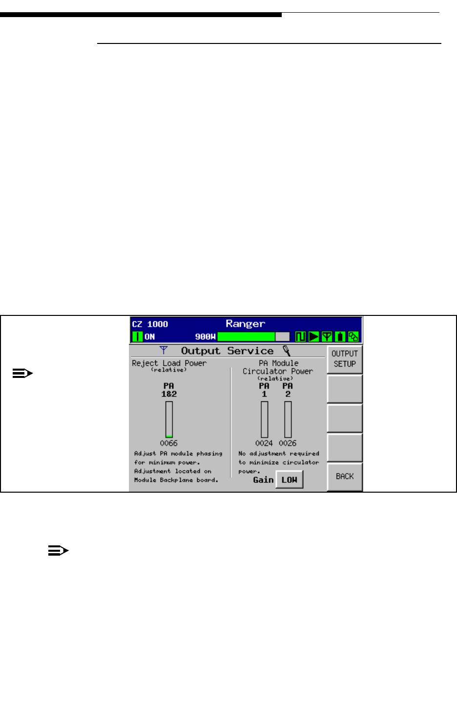
12/24/07 888-2685-001 3-17
WARNING: Disconnect primary power prior to servicing.
Section 3 Operation and Adjustments
Ranger Commissioning Manual
3.7.1 Output Service
This screen is accessed from the Output screen in Figure 3-12. It is used for 2 purposes:
a. To monitor the PA Module Circulator reject power. Provides a bargraph and a
DAC count of 0 - 1023 (0 meaning no reflected power and 1023 being maxi-
mum). This allows for a relative reading which can be monitored for changes
which could mean increased system VSWR or a bad circulator. There is no
adjustment for this reading.
b. To monitor Combiner Reject Load Power in the CZ1000F. Provides a bargraph
and a DAC count of 0 - 1023 (0 meaning no reflected power and 1023 being max-
imum). It is used to adjust the phase relationship of PA Module #2 to minimize
the power to the module combiner reject load. The combiner reject load is actu-
ally a 40dB 1kW attenuator whose output is sent to the RF Monitor board where
it is detected and then A/D converted for the reading shown below the “PA 1&2”
bargraph. It is a relative reading which will simply be minimized with the phasing
adjustment R7 on the Backplane Interface board. See "3.7.2 Module Phasing Pro-
cedure".
Figure 3-13 Output Service Screen
NOTE:
The GAIN button can be toggled between LOW and HIGH, with high only being
used to increase the detector resolution for finer adjustment of the module phas-
ing. Proper phasing can usually be obtained using only the LOW setting and
monitoring the DAC reading.
To Figure 3-15
To Figure 3-12
NOTE:
The left side of the
screen, “Reject Load
Power” is left blank
for the CZ500F.
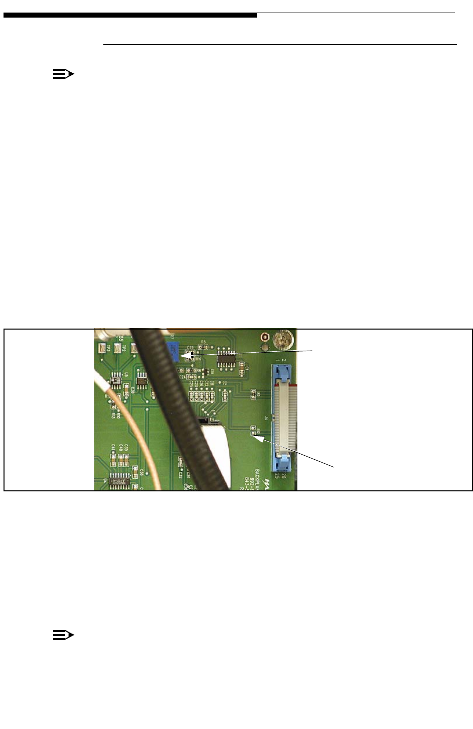
3-18 888-2685-001 12/24/07
WARNING: Disconnect primary power prior to servicing.
Ranger Commissioning Manual
Section 3 Operation and Adjustments
3.7.2 Module Phasing Procedure
NOTE:
This procedure is for the CZ1000F only.
The goal is to minimize the PA module combiner reject load power reading in Figure 3-
13, by adjusting the phase of module #2. The phase of PA module #1 is fixed. The “PA
1&2” reading should be less than 0030 with the GAIN button at the bottom of the
screen set to LOW. If the GAIN button is pressed it will toggle to high, increasing the
detector gain and allowing for finer resolution when adjusting module phasing. The
reading should be less than 0100 with the GAIN set to HIGH.
STEP 1 Check the PA module gain balance on the PA Setup screen, shown in
Figure 3-11 on page 3-14. These current readings should be less than 1
amp apart. If not, refer to "3.6.4.1 PA Setup (Gain Balance)" and adjust
the module gains before proceeding with the module phasing.
STEP 2 Using a digital voltmeter, monitor the test point on the Backplane
Interface board shown in Figure 3-14.
Figure 3-14 Test Point for Module Phasing
STEP 3 Adjust R7 (the only potentiometer) on the Backplane Interface board for
minimum voltage reading on the voltmeter. This should minimize the
reading on the Output Service screen in Figure 3-13. The location of the
Backplane Interface board is shown in Figure 2-1 on page 2-2 under the
letter N.
NOTE:
The reject power should be less than 12W when finished.
Module Phasing
Test point (pad)
Phasing Adjust R7
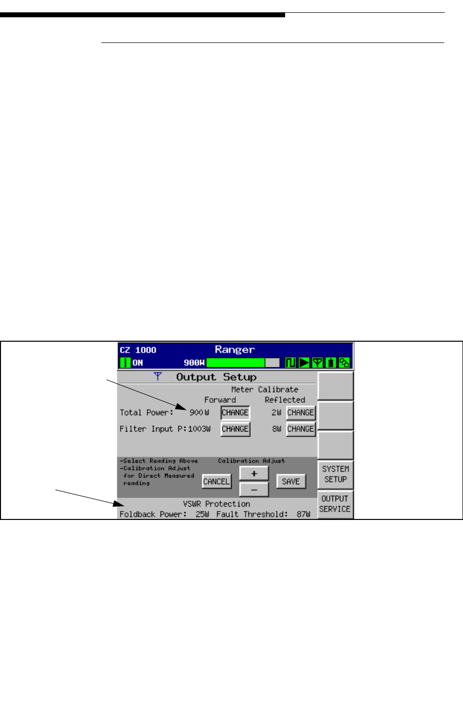
12/24/07 888-2685-001 3-19
WARNING: Disconnect primary power prior to servicing.
Section 3 Operation and Adjustments
Ranger Commissioning Manual
3.7.2.1 Output Setup
This screen is accessed by pressing the Output Setup button on the Output Service
screen in Figure 3-13. It is used to calibrate the filter input power and Total cabinet
Forward and Reflected power (after the filter).
It also calculates the VWSR protection thresholds of Foldback power and Fault
threshold and displays them at the bottom of the screen. These values are based on the
“Nominal Power Output” value entered into the System Setup screen in Figure 3-22 on
page 3-27.
• The foldback level is calculated using a VSWR = 1.4:1. Therefore the actual
foldback power can be calculated as:
Foldback Power = Nominal Power Output x 0.0278
• The fault threshold is calculated using a VSWR = 1.9:1. Therefore the actual
fault threshold can be calculated as:
VSWR Fault Threshold = Nominal Power Output x 0.0963
Figure 3-15 Output Setup Screen
To Figure 3-22
To Figure 3-13
Use the +/- buttons
to make this reading
match the measured
reading at the coupler
Calculated Values

3-20 888-2685-001 12/24/07
WARNING: Disconnect primary power prior to servicing.
Ranger Commissioning Manual
Section 3 Operation and Adjustments
3.7.3 Forward and Reflected Power Calibrations
The following procedure is used to calibrate the forward and reflected power readings
via the Output Setup screen. The forward must be calibrated first, then the reflected can
be calibrated. The procedure requires a digital power meter and a 10dB pad. Since
calibration is relatively easy and quick, it is recommended that both forward and
reflected always be calibrated together.
Forward Power
STEP 1 Connect the digital power meter to the forward power (incident) port on
the directional coupler either before or after the filter. For the location of
these ports see Figure 2-1 on page 2-2, designated B and R. The cables
numbers connected to these ports are #40 for the Total output and #42 at
the filter input.
STEP 2 Measure the power at the forward coupler. The coupler comes with a
table of precision coupling values for the various UHF channels which
should be used as the offset for the digital power meter. Make sure the
coupler serial number matches the coupling table. The coupling values
are also written on stickers which are attached to the couplers at the
factory.
STEP 3 Press the CHANGE button to select the coupler being calibrated (before
or after the filter) and then use the +/- buttons to make the displayed
power match the measured value on the digital power meter.
STEP 4 Press SAVE to store the setting or CANCEL to discard the changes.
Reflected Power
STEP 5 Press the CHANGE button for the desired reflected coupler (before or
after the filter). This temporarily disables the reflected power fault.
STEP 6 Note the forward power and remove the power meter from the forward
coupler. Connect the 10dB pad to the forward power coupler.
STEP 7 Remove the cable from the reflected coupler to be calibrated and connect
it to the 10dB pad. The cables are labeled #50 for the Filter input and
#39 for the Total reflected.
STEP 8 Use the +/- buttons to set the reflected reading on the GUI to 10% of the
forward reading noted earlier.
STEP 9 Press SAVE to store the setting or CANCEL to discard the changes.
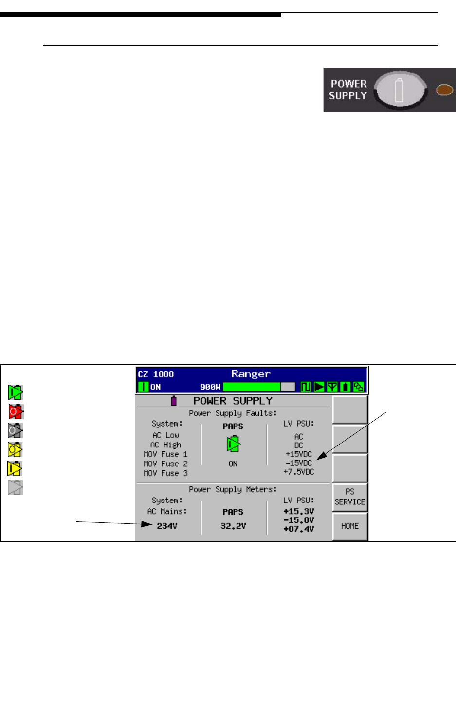
12/24/07 888-2685-001 3-21
WARNING: Disconnect primary power prior to servicing.
Section 3 Operation and Adjustments
Ranger Commissioning Manual
3.8 Power Supply Main Menu
If you press the Power Supply button on the control panel
overlay, it will take you to the screen shown in Figure 3-
16. The Power Supply Menu Tree is shown in Figure 3-32
on page 3-33.
This is the overall Power Supply metering screen for both the PA Power Supply, the
Low Voltage Power Supply Unit or LV PSU and the AC Mains. It is also the fault status
screen for the power supplies. A fault would cause one of the listed faults to be
highlighted red for fault or yellow for a warning condition.
System Faults:
• AC Low - triggers if the AC input to the MOV board goes below 177Vac
• AC High - triggers if the AC input to the MOV board is above 264Vac
• MOV Fuse 1, 2 or 3 - turns yellow if one or more of the MOV protection
fuses on the MOV board is open.
LV PSU Faults are generated by the Vicor power supply unit and monitored by the PS
Monitor board. The dc voltage faults are triggered at +/-15% of nominal.
Figure 3-16 Power Supply Screen
The PAPS (Power Amplifier Power Supply) icon will turn red or yellow if any of the
faults on this screen are activated. Figure 3-16 shows the possible icon configurations
with red being critical faults and yellow simply a warning condition.
To Figure 3-1
7
To Figure 3-3
PAPS Icons:
ON
Fault OFF
OFF (no faults)
ON with warning
OFF with warning
PS module unplugged
Fault threshold
for the dc outpu
ts
is +/-15%.
Calibrated on
PS Service Screen
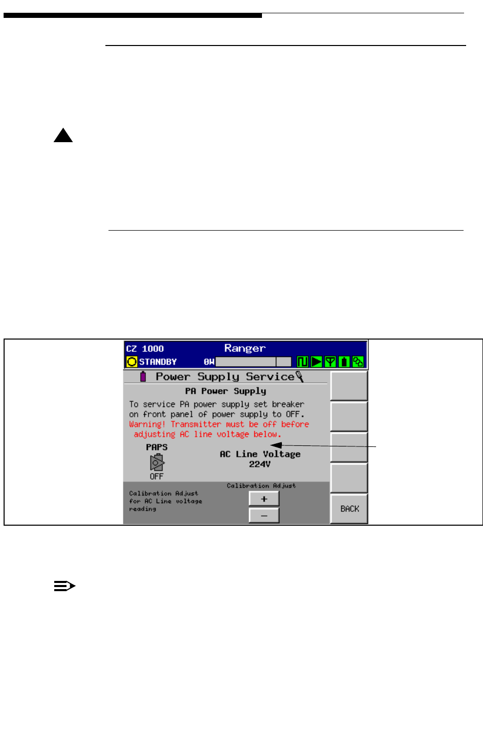
3-22 888-2685-001 12/24/07
WARNING: Disconnect primary power prior to servicing.
Ranger Commissioning Manual
Section 3 Operation and Adjustments
3.8.1 PS Service
This is an on-line help screen telling how to remove a power supply, but also allows for
calibration of the AC Mains reading on the Power supply screen in Figure 3-16.
! CAUTION:
ALWAYS SHUT THE BREAKER OFF ON THE FRONT OF THE PA POWER
SUPPLY BEFORE REMOVING TO PREVENT DAMAGE TO CONTACTS AND/
OR THE POWER SUPPLY.
3.8.1.1 AC Mains Meter Calibration
The AC Mains calibration must be done during transmitter installation, but will most
likely not require adjustment again unless the MOV or PS Monitor board is changed.
This is a critical transmitter adjustment as this reading is used for the AC high and AC
low faults.
Figure 3-17 PS Service Screen
NOTE:
This calibration should always be done with the transmitter shut off. This adjust-
ment can cause various power supply faults to appear momentarily, but can be
safely ignored. If the transmitter is turned ON, these faults can cause the transmit-
ter to mute momentarily.
To Figure 3-16
To calibrate,
simply measure
your ac mains
voltage at the wall
disconnect and
then use the +/-
buttons here to set
this reading to the
same as the
measured value.
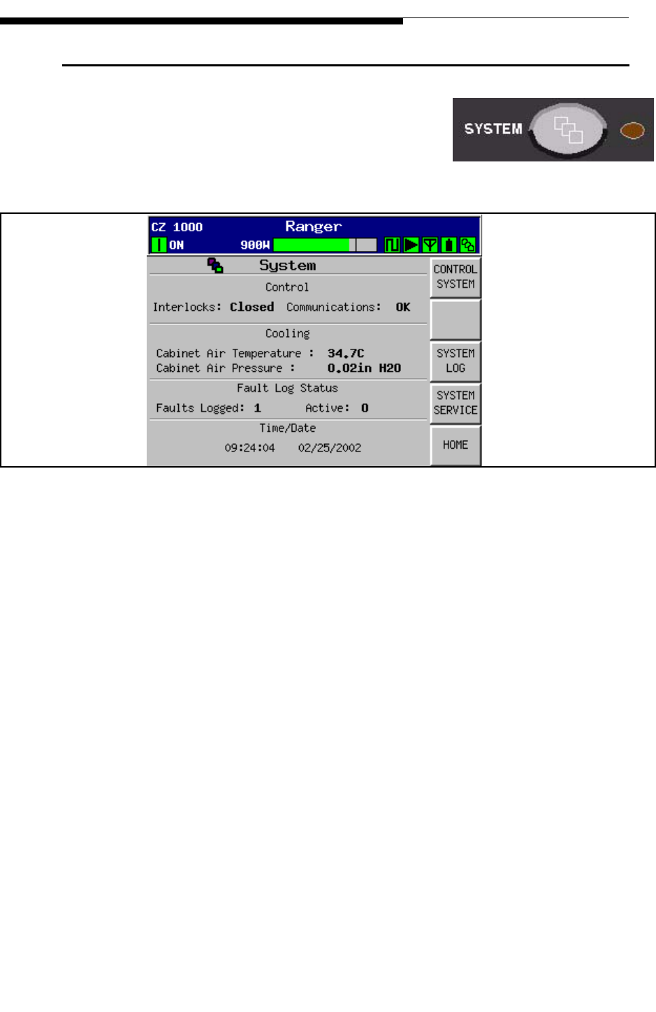
12/24/07 888-2685-001 3-23
WARNING: Disconnect primary power prior to servicing.
Section 3 Operation and Adjustments
Ranger Commissioning Manual
3.9 System Main Menu
If you press the System button on the control panel
overlay, it will take you to the screen shown in Figure 3-
18. The System Menu Tree is shown in Figure 3-33 on
page 3-34.
Figure 3-18 System Main Menu
This screen is basically a System Main Menu which gives overall status information
about the screens which can be accessed from here. This includes:
a. Control System - For more in-depth information press “Control System”
1. External Interlocks - Can read Open or Closed (as shown)
2. Communications - Can read OK or Fault. This could be a problem with any
of the serial communication links inside the transmitter.
b. System Log - For more in-depth information press “System Log”
1. Gives the current date and time (MM/DD/YYYY and HH:MM:SS)
2. Faults Logged - Total of fault list including Active and Inactive Faults
3. Active - Shows how many Active faults are present
c. System Service - Gives frequency and selected channel number. Pressing “Sys-
tem Service” gives access to configuration, touchscreen calibration, software and
hardware revisions, time and date setting, screen saver time-out and LCD display
contrast.
SYSTEM
To Figure 3-19
To Figure 3-20
To Figure 3-21
To Figure 3-3
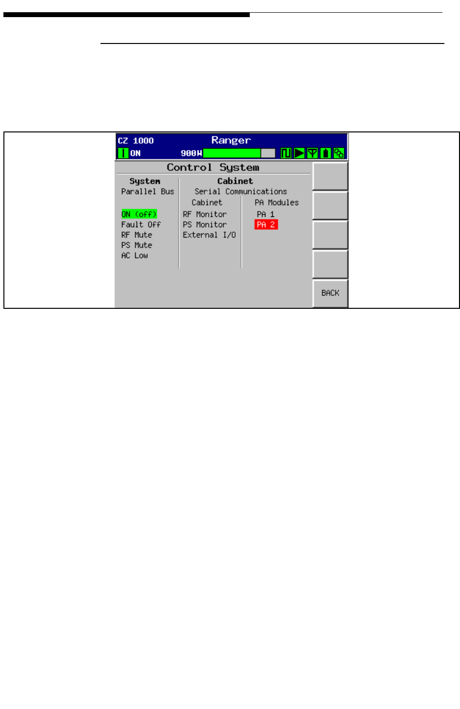
3-24 888-2685-001 12/24/07
WARNING: Disconnect primary power prior to servicing.
Ranger Commissioning Manual
Section 3 Operation and Adjustments
3.9.1 Control System
The Control system screen in Figure 3-19 is a status and fault screen for the parallel
control bus lines and the internal serial communication bus to each of the controller
boards and the PA Module(s).
Figure 3-19 Control System Screen
To Figure 3-18

12/24/07 888-2685-001 3-25
WARNING: Disconnect primary power prior to servicing.
Section 3 Operation and Adjustments
Ranger Commissioning Manual
3.9.2 System Log
This screen is accessed by pressing the System Log button on the System screen in
Figure 3-18. It is a complete listing of all transmitter and system faults in the order in
which they occurred. It can hold up to 99 faults. Active Faults will be highlighted and
cannot be reset. All other faults will be cleared when the RESET button is pressed.
Figure 3-20 shows that only faults #7 and #8 are active (at least on this screen), all other
faults are inactive. Use the Next and Previous buttons to view the entire list.
This should be thought of as a record of the faults which have occurred or as a summary
point of all transmitter faults. Individual faults may be investigated by pressing any of
the 5 hardware buttons to the right of the GUI display and then if necessary pressing
any highlighted buttons on the GUI to go deeper into the system.
The faults which show up on any particular screen are discussed with that screen image
in this section.
Figure 3-20 System Log Screen
To Figure 3-18
Note:
Date format is
DD/MM/YY
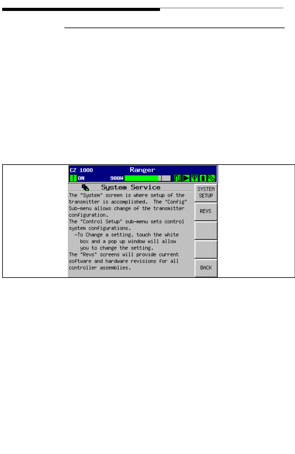
3-26 888-2685-001 12/24/07
WARNING: Disconnect primary power prior to servicing.
Ranger Commissioning Manual
Section 3 Operation and Adjustments
3.9.3 System Service
This screen is accessed by pressing the System Service button in Figure 3-18. This
screen simply provides information concerning the use of the sub-menus accessed from
this point. These are:
a. System Setup
1. Control Setup
a. Touchscreen Calibration
2. Config (Configuration)
b. SW REVS (Software Revisions)
1. HW REVS (Hardware Revisions)
Figure 3-21 System Service Screen
To Figure 3-22
To Figure 3-27
To Figure 3-18
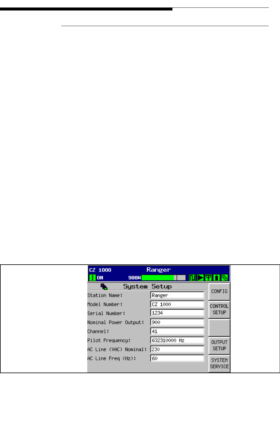
12/24/07 888-2685-001 3-27
WARNING: Disconnect primary power prior to servicing.
Section 3 Operation and Adjustments
Ranger Commissioning Manual
3.9.3.1 System Setup
This screen provides a way to change important pieces of information which are then
used throughout the GUI. To make a change, simply touch the white text box and a pop-
up window will allow you to enter the new information. Be sure to press CANCEL if
you do not wish to make a change.
a. Station Name - This can be up to 24 characters and will appear at the top of Every
GUI screen.
b. Model Number - This value is selected from a pull down list by touching the
white box. The model number chosen must match the transmitter name plate. It is
used to gray out portions of the GUI screens which are not used by some models.
c. Serial Number - Please note this for reference before calling for support.
d. Nominal Power Output (after all system filters) - This number is used to:
1. Set the 100% mark on the power bargraph at the top of every GUI screen.
2. Calculate the VSWR foldback and fault thresholds, see "3.7.2.1 Output
Setup" on page 3-19.
e. Channel - Used by the PA module for calibration.
f. Pilot Frequency - Exact station pilot frequency should be entered in Hz. This
entry has no function and is for informational purposes only.
g. AC Line (VAC) Nominal - This number should reflect your nominal AC line
voltage as measured at the disconnect.
h. AC Line Frequency (Hz) - 50 or 60Hz. Should reflect your line frequency.
Figure 3-22 System Setup Screen
To Figure 3-2
3
To Figure 3-2
4
To Figure 3-1
5
To Figure 3-2
1
Note:
Be sure to press CANCEL
on any pop-up window if
you do not wish to make
any changes. Pressing
DONE without making an
entry will cause the field to
revert to its default and the
previous information will
be lost.
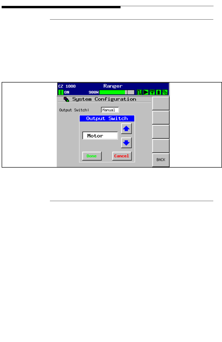
3-28 888-2685-001 12/24/07
WARNING: Disconnect primary power prior to servicing.
Ranger Commissioning Manual
Section 3 Operation and Adjustments
3.9.3.1.1 System Configuration
This screen is used to configure the transmitter to operate with either a 3 port patch
panel or a motorized RF switch. To change this setting touch the white text box and the
Output Switch pop up widow will appear (as shown in Figure 3-23). There are only 2
choices, “Manual” for the manual patch panel or “Motor” for a motorized switch.
Selecting Motor activates the XMTR TO ANTENNA button in the Output Control
section of the Output screen in Figure 3-12 on page 3-15.
Figure 3-23 System Output Switch Configuration
3.9.3.1.2 Control Setup
To set any of the parameters on this screen, simply touch inside the text box and a pop-
up menu will appear with the appropriate information (number pad or keyboard).
This screen allows the user to set the Date and Time which will be used for reporting
and for the fault log. The real time clock is backed up by a battery on the Main
Controller to prevent having a reset due to a power outage.
It also allows for adjustment of the Contrast of the GUI LCD display. The display
contrast will adjust dynamically as the number is changed to allow for room lighting. A
setting in the mid 80’s is normal.
The Screen Saver setting allows the user to select how long it will take for the screen to
blank out due to inactivity.
Password: The last box allows a password to be entered. The password protects against
unwanted entry to the transmitter configuration and setup screens, basically any screen
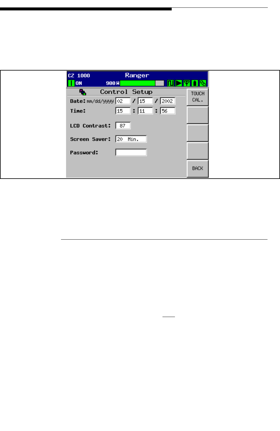
12/24/07 888-2685-001 3-29
WARNING: Disconnect primary power prior to servicing.
Section 3 Operation and Adjustments
Ranger Commissioning Manual
in which information can be changed. The default password is 1895, which will
override any other password and allow access.
The only function button is the Touch Cal or Touchscreen Calibration. This should not
require routine adjustment. The procedure is given next.
Figure 3-24 Control Setup Screen
3.9.3.1.3 Touch Screen Calibration
If the touch screen soft buttons on the GUI are working and seem to be accurate, then
this procedure is not required. If the soft buttons on the touch screen do not seem to
work or can only be activated by pressing outside the button graphic, then a simple
touch screen calibration will have to be done as follows:
STEP 1 Go to the touch screen calibration setup screen by pressing the Touch
Cal button in Figure 3-24. If you are not able to get to the screen, open
the control panel and press and hold the Remote Enable and Disable
buttons at the same time and momentarily reset the main controller. The
Main Controller Reset button is located near the center of the board
(directly behind the GUI). Keep the Enable and Disable buttons pressed
until the display is up and running. After the micro resets, the Main
Controller will prompt the operator to calibrate the touch screen.
STEP 2 Once you see the screen in Figure 3-25, simply touch the X in the first 2
screens. This will get you to the first screen in Figure 3-26.
To Figure 3-25 &
Figure 3-26
To Figure 3-22
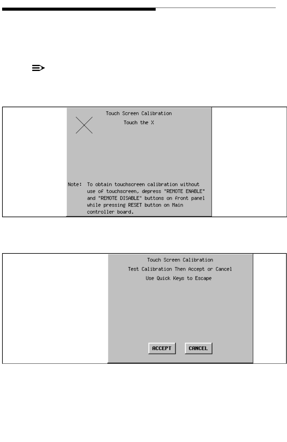
3-30 888-2685-001 12/24/07
WARNING: Disconnect primary power prior to servicing.
Ranger Commissioning Manual
Section 3 Operation and Adjustments
STEP 3 To test the calibration simply touch the screen in several places to make
sure an X shows up where you touched.
STEP 4 If the calibration is good, then press ACCEPT. If not, press CANCEL
and the cal procedure will be started over.
NOTE:
The procedure can be aborted by pressing any of the 5 hardware Quick keys on
the control panel.
Figure 3-25 Touchscreen Calibration Screen
Figure 3-26 Touchscreen Calibration Test Screen
Touch this screen in several
places to make sure an X shows
up exactly where the screen
was touched.
NOTE:
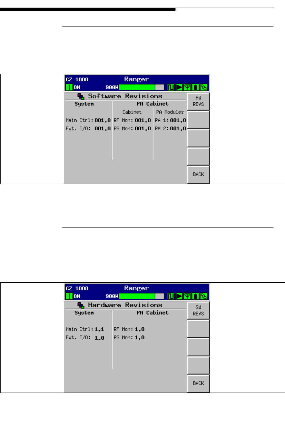
12/24/07 888-2685-001 3-31
WARNING: Disconnect primary power prior to servicing.
Section 3 Operation and Adjustments
Ranger Commissioning Manual
3.9.3.2 Software Revisions (SW REVs)
This screen shows the software revision for all transmitter controllers and PA module
controllers. This information should be known before calling for technical support.
Figure 3-27 Software Revisions Screen
3.9.3.2.1 Hardware Revisions
This screen shows the hardware revisions for all of the transmitter control boards. This
information is read from each board and is set using jumpers at the factory and should
be known before calling technical support.
Figure 3-28 Hardware Revisions Screen
To Figure 3-28
To Figure 3-21
To Figure 3-27
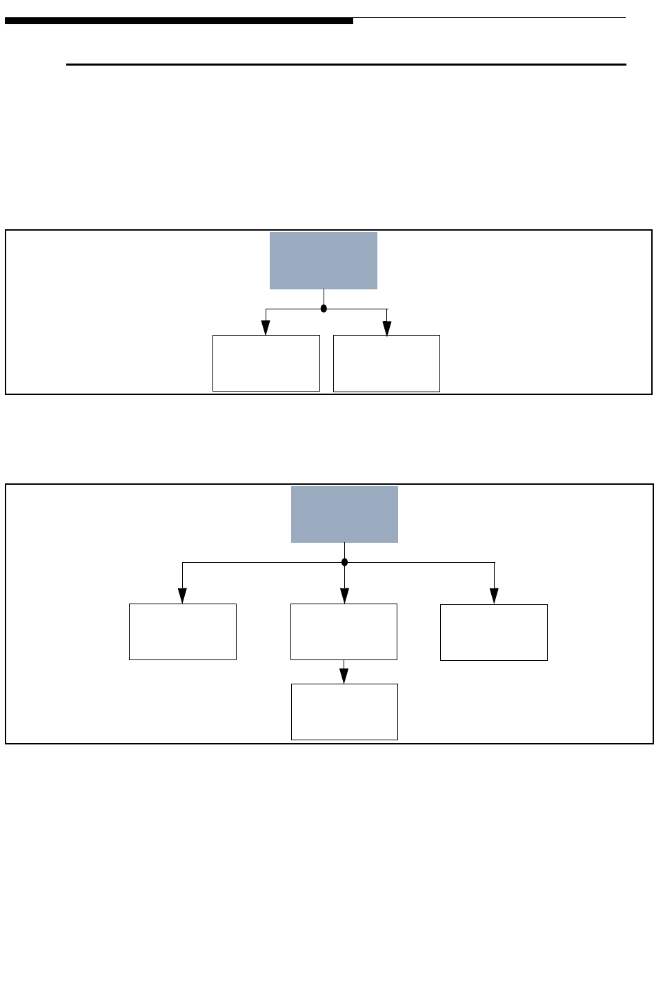
3-32 888-2685-001 12/24/07
WARNING: Disconnect primary power prior to servicing.
Ranger Commissioning Manual
Section 3 Operation and Adjustments
3.10 GUI Menu Structures
The following figures are simply showing all of the possible screens which can be
accessed on the GUI. This is mainly helpful when learning to navigate. The shaded
block at the top of each menu tree represents the Main Menu which is accessed using
the Quick navigation hardware button on the Control Panel or one of the 5 software
buttons on the right side of the HOME Page. Each successive level represents the
software buttons which will show up on the right side of the GUI.
Figure 3-29 Drive Chain Menu Structure
Figure 3-30 Power Amp Menu Structure
DRIVE
CHAIN
Drive
Faults Drive
Service
Main Menu
POWER
AMP
PA
Faults PA
Meters PA
Service
PA
Data
Main Menu
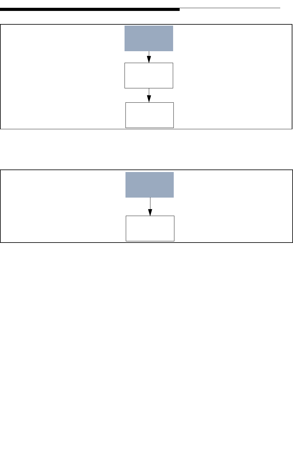
12/24/07 888-2685-001 3-33
WARNING: Disconnect primary power prior to servicing.
Section 3 Operation and Adjustments
Ranger Commissioning Manual
Figure 3-31 Output Menu Structure
Figure 3-32 Power Supply Menu Structure
OUTPUT
Output
Service
Output
Setup
Main Menu
POWER
SUPPLY
PS
Service
Main Menu
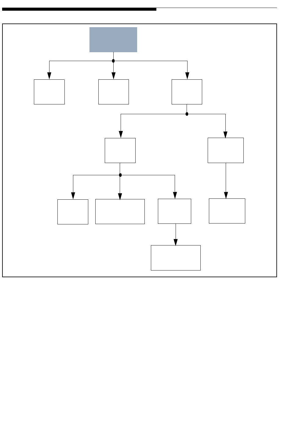
3-34 888-2685-001 12/24/07
WARNING: Disconnect primary power prior to servicing.
Ranger Commissioning Manual
Section 3 Operation and Adjustments
Figure 3-33 System Menu Structure
SYSTEM
Control
Output
Setup
System
Log System
Service
System
Setup Software
Revision
Configuration Control
Setup Hardware
Revision
Touch Screen
Calibration
Main Menu
System
(output Switch )

12/24/07 888-2685-001 4-1
WARNING: Disconnect primary power prior to servicing.
Ranger Commissioning Manual
Section 4
RF Testing 4
4.1 Introduction
This section defines suggested data and measurements that are to be included in the
report that should be generated as part of a Ranger Transmitter Proof of Performance.
The various sections of the report and measurements are defined and in some instances
samples are provided.
4.2 Proof Testing and Report
4.2.1 Report Cover Page
Title: Engineering Report of Television Transmitter Performance Characteristics
•Station Call Letters:
•Channel:
•Transmitter Model:
•Measured By:
•Measurement Date:
•Signature of Field Engineer:

4-2 888-2685-001 12/24/07
WARNING: Disconnect primary power prior to servicing.
Ranger Commissioning Manual
Section 4 RF Testing
4.2.2 Table of Contents
Table 4-1 describes the content of a typical Performance Report. The page numbers are
added as the report is generated. The report contents may also need to be modified
depending on specific site requirements or equipment provided.
Table 4-1 Typical Report Table of Contents (sample)
Section Title Report
Page No.
Facilities Authorized in Construction Permit
Transmitter Location
Transmitter Type and Power Output
Block Diagram for Measuring Transmitter
Test Equipment List
Output Power
Frequency Tolerance
Non-Linear Precorrection (Shoulders & Amplitude Response)
Out of Band Emissions
Spurious Emissions
Linear Precorrection (Group Delay & Amplitude Response)
Modulation Error Ratio
Systems Metering
Station Test Load Return Loss
Software Versions
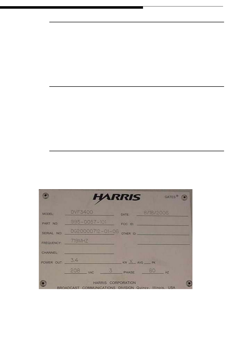
12/24/07 888-2685-001 4-3
WARNING: Disconnect primary power prior to servicing.
Section 4 RF Testing
Ranger Commissioning Manual
4.2.3 Facilities Authorized in Construction Permit
•Name of Applicant:
•Call Letters:
•Channel Number:
•File Number of License:
4.2.4 Transmitter Location
•State:
•County
•City:
•Street Address:
4.2.5 Transmitter Manufacturer ID Plate
Insert photograph of transmitter identification plate in this section. If photo is not
available transcribe the data from the nameplate into the report.
Figure 4-1 Sample Identification Plate

4-4 888-2685-001 12/24/07
WARNING: Disconnect primary power prior to servicing.
Ranger Commissioning Manual
Section 4 RF Testing
4.2.6 RF Power Summary
TPO (dBK) - Transmission Line Loss (dB) + Antenna Gain (dB) = ERP (dBK)
10 x Log TPO(kW) = dBK
4.2.7 Antenna and Bandpass Filter Information
•Filter Manufacturer:
•Filter Type:
•Filter Serial No.:
•Antenna Manufacturer:
•Antenna Type:
•Antenna Serial No.:
Table 4-2 RF Power Budget (Average, Digital)
Description dBK Watts
Amplifier(s) Rated Power
Transmitter System Rated Power
Transmitter Power Output (TPO)
Transmission Line Loss
Antenna Input Power
Antenna Power Gain (Maximum)
Effective Radiated Power (Average)
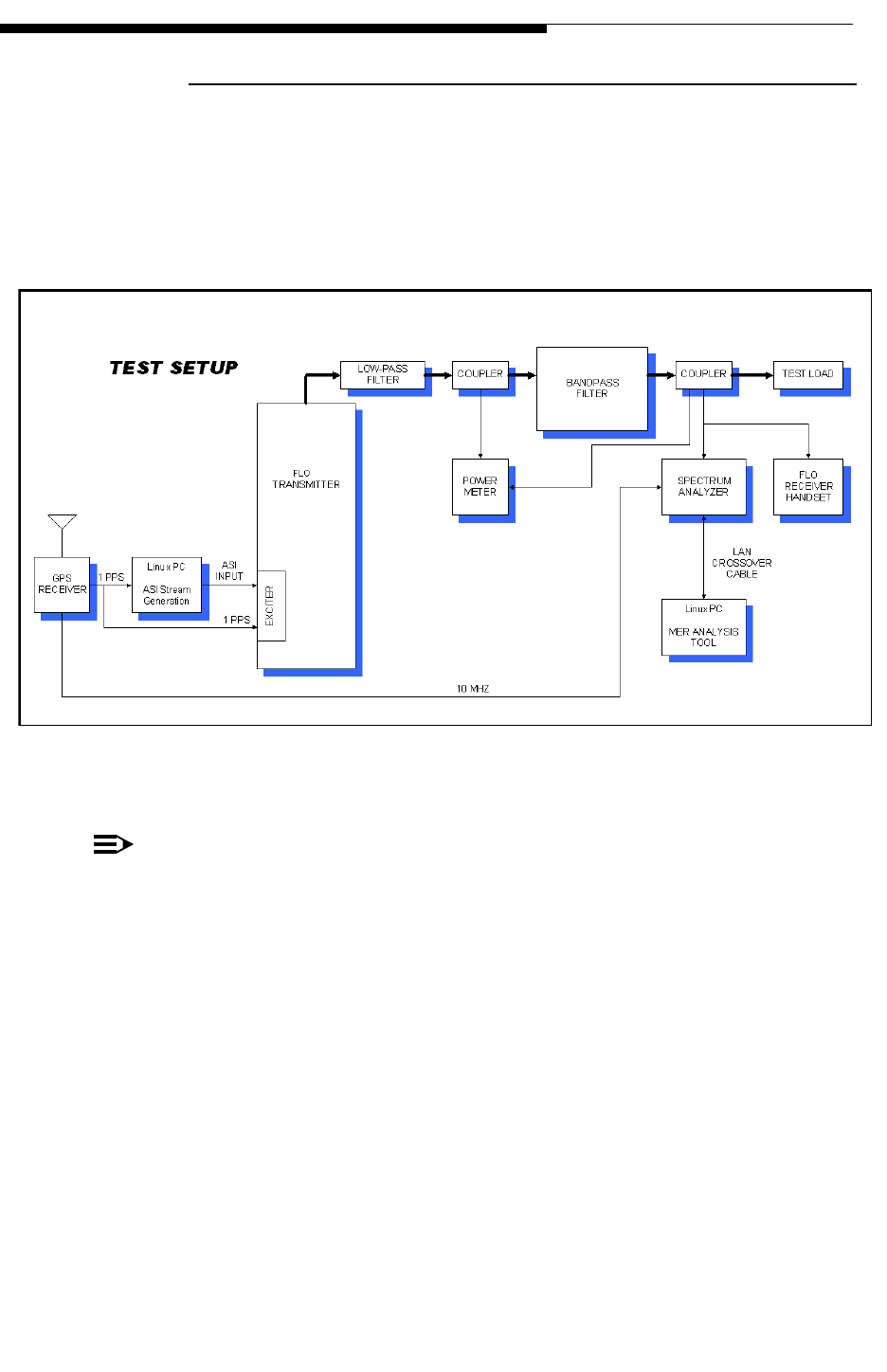
12/24/07 888-2685-001 4-5
WARNING: Disconnect primary power prior to servicing.
Section 4 RF Testing
Ranger Commissioning Manual
4.2.8 System Block Diagram
A simplified block diagram should be included in the report. A sample diagram is
shown below. The diagram should define signal flow and major components in the
system under test. The diagram may vary from site to site depending on the specific site
layout and equipment.
Figure 4-2 Block Diagram of the MER Measurement Setup
NOTE:
This diagram shows the measurement being taken from fwd coupler DC1 of the
filter assembly. If desired, the measurement can also be taken from exciter output
and fwd couplers of the transmitter.
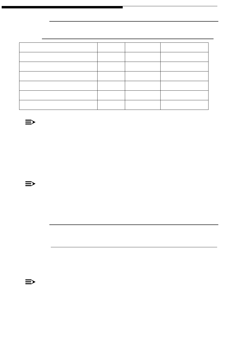
4-6 888-2685-001 12/24/07
WARNING: Disconnect primary power prior to servicing.
Ranger Commissioning Manual
Section 4 RF Testing
4.2.9 Test Equipment List
NOTE:
The test equipment outlined above is an example of typical equipment used to
perform the measurements. Other equipment with similar capabilities can be sub-
stituted. The serial nThe Qualcomm MER tool set consists of hardware and soft-
ware. In addition to the FSQ3 spectrum analyzer a Linux based PC is needed to
control the analyzer, a Linux based PC is needed to generate the test ASI stream
to feed the Apex exciters, and a GPS receiver to provide a 1PPS reference signal.
The software is provided by Qualcomm.
NOTE:
Rather than use two Linux PC’s a single, high performance, Linux PC could be
used to peform both functions. An additional Windows PC will be needed to ana-
lyze the measured data sets.
4.2.10 Transmitter Power Output
4.2.10.1 Objective
To verify the nominal rated RF output power (average) of the transmitter in digital
mode (FLO modulation).
NOTE:
The transmitter output power is measured at the forward output precision direc-
tional coupler located before the filter. The output of the transmitter must be con-
nected to an appropriately sized dummy load or to the MediaFLO channel filter
assembly which is connected to a dummy load.
Table 4-3 Test Equipment for Measurements
Test Equipment Mfg. Model Serial No.
Spectrum Analyzer R&S FSQ3
Network Analyzer HP HP8714B
RF Power Meter HP E4418A
Power Sensor HP 8482H
Frequency Counter HP HP53181A
Qualcomm MER Tool Set N/A N/A
12/24/07 888-2685-001 4-7
WARNING: Disconnect primary power prior to servicing.
Section 4 RF Testing
Ranger Commissioning Manual
4.2.10.2 Requirement(s)
The output power shall be measured using a true RMS RF power meter and a precision
directional coupler. Output power shall be 375 or 750 W (within +/- 10%)
4.2.10.3 Setup and Test Equipment
Table 4-4 Power Measurement Setup
Transmitter Exciter
Status 1 Active on Exciter A External GPS Active
Status 2 Active on Exciter B External GPS Active
Table 4-5 Power Measurement Test Equipment
True RMS power meter
Spectrum Analyzer
Spectrum Analyzer
4-8 888-2685-001 12/24/07
WARNING: Disconnect primary power prior to servicing.
Ranger Commissioning Manual
Section 4 RF Testing
4.2.10.4 Power Measurement Procedure
4.2.10.5 Power Measurement Test Results
Step Procedure Description Expected Observation
1Configure the transmitter to operate
on air with Exciter A with
precorrector settings to:
Non-Linear Precorrection = ADAPT
Linear Precorrection = BYPASS
2Connect the true RMS power meter
probe to the transmitter output
directional coupler (forward port
located before the filter). The
transmitter output should be
connected to the load.
Measured power output is
within +/- 10% of rated
power
3Configure the transmitter to operate
on air with Exciter B with
precorrector settings to:
Non-Linear Precorrection = ADAPT
Linear Precorrection = BYPASS
Measured Pout is within +/-
10% of rated power
Expected Results Result (circle)
Rated Pout with Exciter A at output of directional couplers. PASS FAIL
Rated Pout with Exciter B at output of directional couplers. PASS FAIL

12/24/07 888-2685-001 4-9
WARNING: Disconnect primary power prior to servicing.
Section 4 RF Testing
Ranger Commissioning Manual
4.2.11 Frequency Tolerance
4.2.11.1 Objective
To verify the Channel Center Frequency meets the tolerance requirements.
The transmitter will be operated in CW mode (719 MHz for U.S. applications and at
other frequencies to be defined by Qualcomm for international operation) while the
frequency is measured at the transmitter forward output directional coupler. Output
power must be adjusted to 375 or 500 watts +/- 10% (output level depends on power
level of transmitter).
4.2.11.2 Requirement(s)
The relative maximum frequency difference (|f-fc|/fc) between the mean actual transmit
carrier (f) frequency and the specified transmit frequency (fc) shall be less than 1 x 10⁻⁹
with the external reference connected.
With external reference disconnected, the relative maximum frequency difference shall
be less than 1 x 10⁻⁸ for at least 24 hours.
4.2.11.3 Setup and Test Equipment
Table 4-6 Frequency Tolerance Setup
Transmitter Exciter
Status 1 Active on Exciter A External GPS Active
Status 2 Standby on Exciter B External GPS Active
Table 4-7 Frequency Tolerance Test Equipment
Frequency Meter (error < +/- 0.72 Hz
RF Test Cables (with known and measured losses)
4-10 888-2685-001 12/24/07
WARNING: Disconnect primary power prior to servicing.
Ranger Commissioning Manual
Section 4 RF Testing
4.2.11.4 Frequency Tolerance Procedure
NOTE:
The operating frequency of 719 MHz is for U.S. operation. Qualcomm may
define other UHF frequencies for international operation.
4.2.11.5 Frequency Tolerance Test Results
Step Procedure Description Expected Observation
1Generate a CW tone as per the
instructions in Appendix B.
2Using a frequency counter (or a
spectrum analyzer) measure the fre-
quency of the tone coming out of the
Exciter for 30 minutes (Provide the
frequency counter/spectrum ana-
lyzer with a reference signal derived
from the same GPS signal that the
Exciter has).
The maximum deviation of the car-
rier tone from 719000000 should be
less than ±1.0 Hz
3Set FLO FPGA, SFN mode = Off.
Also, increase the SFN limit to 500
microseconds. Remove the 1PPS
signal, and using the frequency
counter/spectrum analyzer measure
the frequency of the tone overnight/
24 hours.
The maximum deviation of the car-
rier tone from 719000000 should be
less than ±10.0 Hz
Expected results Result (circle)
Maximum deviation with GPS signal is less than +/- 1.0 Hz. PASS FAIL
Maximum deviation without GPS signal is less than +/- 10.0
Hz.
PASS FAIL

12/24/07 888-2685-001 4-11
WARNING: Disconnect primary power prior to servicing.
Section 4 RF Testing
Ranger Commissioning Manual
4.2.12 Non-Linear Precorrection (Shoulders & Amplitude
Response)
4.2.12.1 Objective
To verify the shoulders with the non-linear precorrection set to ADAPT mode.
The transmitter will be operated in digital mode (FLO modulation) at 719 MHz and the
RF spectrum is measured at the transmitter output directional coupler forward port.
NOTE:
The operating frequency of 719 MHz is for U.S. operation. Qualcomm may
define other UHF frequencies for international operation
The transmitter must be connected to the MediaFLO channel filter assembly terminated
in a dummy load.
4.2.12.2 Requirement(s)
The measured shoulder levels should be <-36 dB
4.2.12.3 Setup and Test Equipment
Table 4-8 Non-Linear Precorrection Setup
Transmitter Exciter
Status 1 Active on Exciter A External GPS Active
Status 2 Active on Exciter B External GPS Active
Table 4-9 Non-Linear Precorrection Test Equipment
Spectrum Analyzer
RF Test Cables (with known and measured losses)

4-12 888-2685-001 12/24/07
WARNING: Disconnect primary power prior to servicing.
Ranger Commissioning Manual
Section 4 RF Testing
4.2.12.4 Non-Linear Precorrection Procedure
Step Procedure Description Expected Observation
1Configure the transmitter to
operate on air with Exciter A
with precorrector settings to:
Non-Linear Precorrection =
ADAPT
Linear Precorrection = BYPASS
Then connect the spectrum
analyzer to the transmitter
output directional coupler
forward port.
RF Spectrum output should be
clean.
2Configure the spectrum analyzer
as follows:
Center Frequency = 719 MHz
Span = 10 MHz
Resolution BW = 30 KHz
Video BW = 300 Hz
Sweep = Auto
Sweep Points = 10001
Amplitude Reference Level = 10
dB
Amplitude Attenuation = 30 dB
3Measure shoulders level at Fc +/
- 3.0 MHz with Exciter A Shoulders level < -36 dB
4Measure shoulders level at Fc +/
- 3.0 MHz with Exciter B Shoulders level < -36 dB
5Repeat steps 3-4 with the
spectrum analyzer configured as
follows:
Start Frequency = 698 MHz
Stop Frequency = 746 MHz
Resolution BW = 30 KHz
Video BW = 300 Hz
Sweep = Auto
Sweep Points = 10001
Amplitude Reference Level = 10
dB
Amplitude Attenuation = 30 dB
Results should be consistent with
those from steps 3-4.
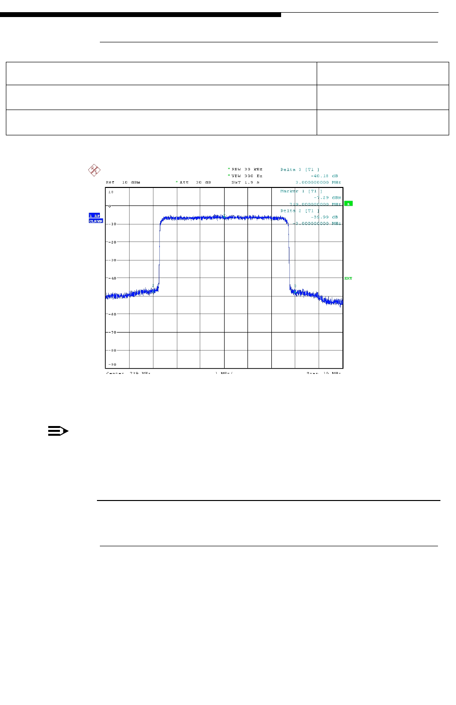
12/24/07 888-2685-001 4-13
WARNING: Disconnect primary power prior to servicing.
Section 4 RF Testing
Ranger Commissioning Manual
4.2.12.5 Non-Linear Precorrection Test Results
Figure 4-3 Non-Linear Precorrection Plot
NOTE:
The operating frequency of 719 MHz is for U.S. operation. Qualcomm may
define other UHF frequencies for international operation
4.2.13 Out of Band Emissions
4.2.13.1 Objective
To verify the out of band spurious emissions at the output of band pass filter.
The transmitter will be operated in digital mode (FLO modulation) at the nominal rated
RF output power at 719MHz channel frequency.
Expected results Result (circle)
Shoulders level <-36 dB with Exciter A at FC +/- 3.0 MHz. PASS FAIL
Shoulders level <-36 dB with Exciter B at FC +/- 3.0 MHz PASS FAIL
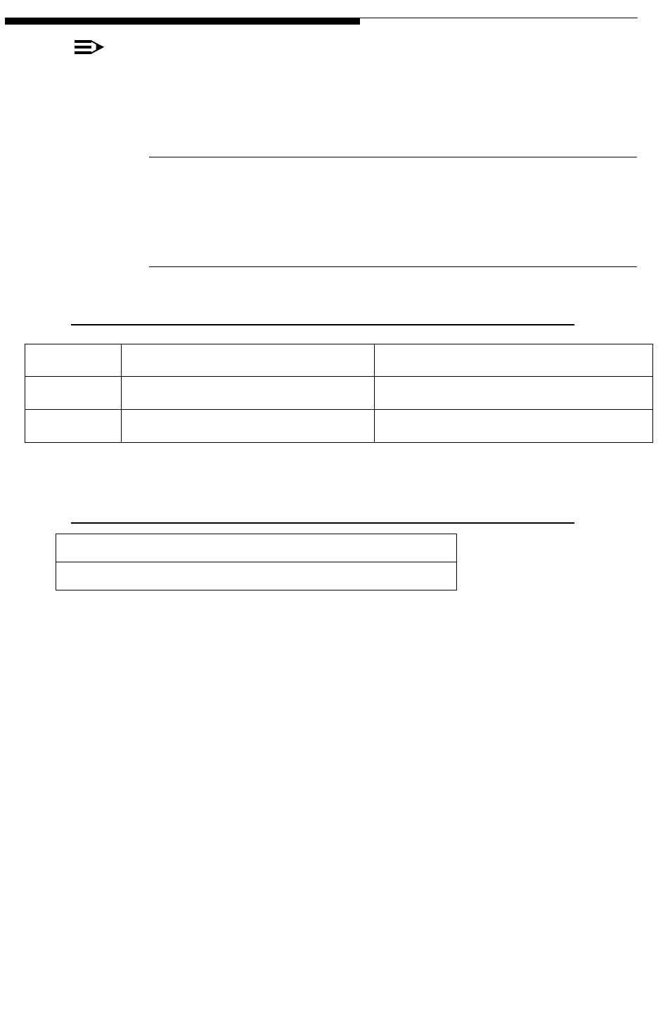
4-14 888-2685-001 12/24/07
WARNING: Disconnect primary power prior to servicing.
Ranger Commissioning Manual
Section 4 RF Testing
NOTE:
The operating frequency of 719 MHz is for U.S. operation. Qualcomm may
define other UHF frequencies for international operation
4.2.13.2 Requirement(s)
See Expected Observations column in the following Procedure.
4.2.13.3 Setup and Test Equipment
Table 4-10 Out of Band Emissions Setup
Transmitter Exciter
Status 1 Active on Exciter A External GPS Active
Status 2 Active on Exciter B External GPS Active
Table 4-11 Out of Band Emissions Test Equipment
Spectrum Analyzer
RF Test Cables (with known and measured losses)

12/24/07 888-2685-001 4-15
WARNING: Disconnect primary power prior to servicing.
Section 4 RF Testing
Ranger Commissioning Manual
4.2.13.4 Out of Band Emissions Procedure
Step Procedure Description Expected Observation
1Configure the transmitter to operate
on air with Exciter A with
precorrector settings to:
Non-Linear Precorrection = ADAPT
Linear Precorrection = ADAPT
Then connect the spectrum analyzer
to the transmitter output of the
bandpass filter.
RF Spectrum output should be
clean.
2Configure the spectrum analyzer as
follows:
Start Frequency = 698 MHz
Stop Frequency = 715.9 MHz
Resolution BW = 100 KHz
Video BW = 300 Hz
Sweep = Auto
Sweep Points = 10001(number of
points in sweep)
Amplitude Reference Level = 10 dB
Amplitude Attenuation = 30 dB
Then measure 698–715.9 MHz with
Exciter A on air.
Less than -38 dBm/100 kHz
3Change the following spectrum
analyzer settings:
Start Frequency = 722.1 MHz
Stop Frequency = 746 MHz.
Then measure 722.1–746 MHz with
Exciter A on air.
Less than -38 dBm/100 kHz
4Change the following spectrum
analyzer settings:
RBW = 30 Khz
Start Frequency = 715.9 MHz
Stop Frequency = 716 MHz.
Then measure 715.9-716 MHz with
Exciter A on air.
Less than -38 dBm/30 kHz
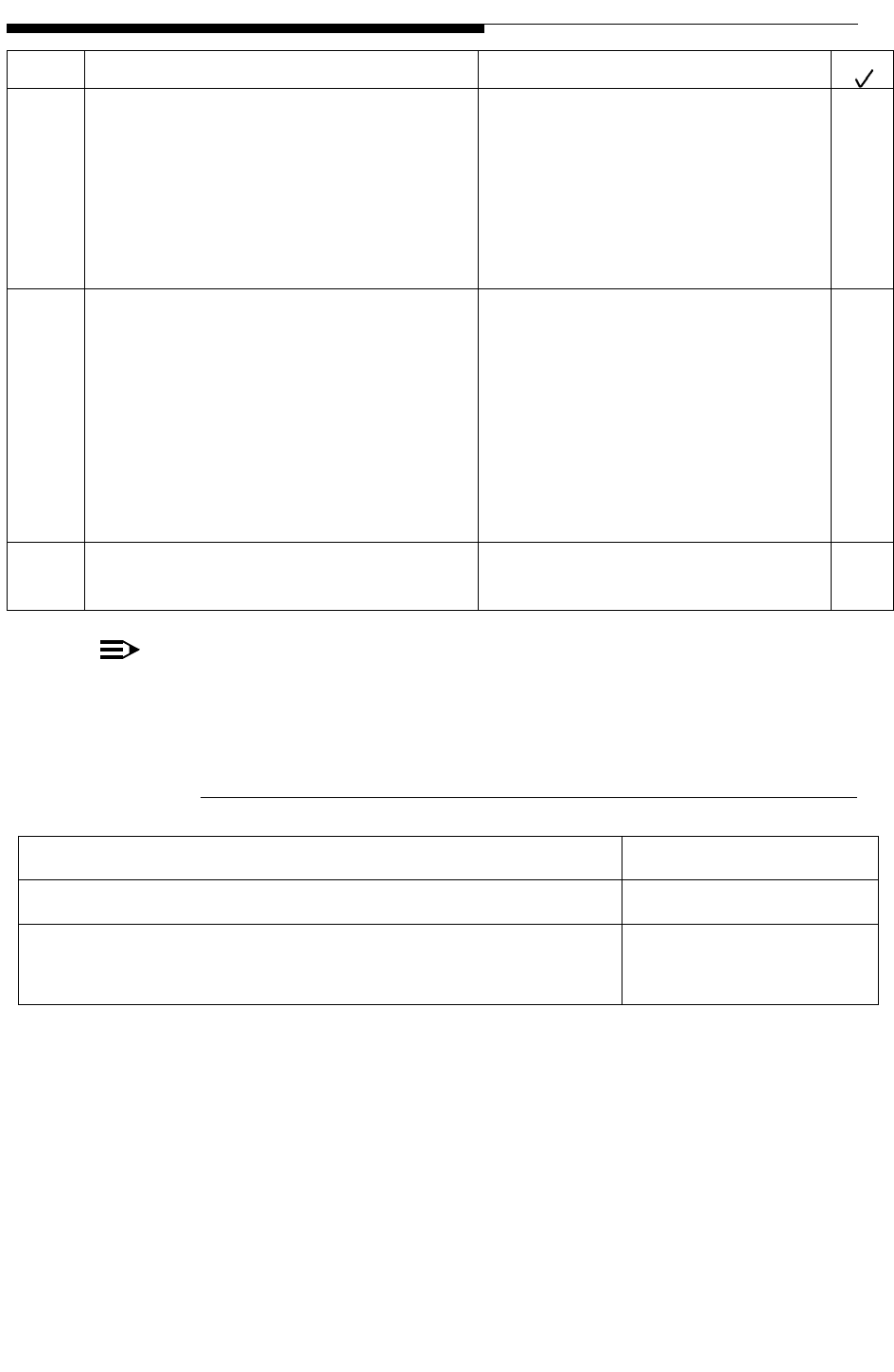
4-16 888-2685-001 12/24/07
WARNING: Disconnect primary power prior to servicing.
Ranger Commissioning Manual
Section 4 RF Testing
NOTE:
The operating frequency of 719 MHz is for U.S. operation. Qualcomm may
define other UHF frequencies for international operation.
4.2.13.5 Out of Band Emissions Test Results
The following plots show the typical results:
5Change the following spectrum
analyzer settings:
RBW = 30 Khz
Start Frequency = 722 MHz
Stop Frequency = 722.1 MHz.
Then measure 722 – 722.1 MHz
with Exciter A on air.
Less than -38 dBm/30 kHz
6Attach a notch filter between the
spectrum analyzer and the output of
the bandpass filter.
Change the following spectrum
analyzer settings:
RBW = 100 kHz
Start Frequency = 698 MHz
Stop Frequency = 746 MHz.
Then measure 698-746 MHz
Less than -38 dBm/100 kHz
7Repeat steps 2-6 with Exciter B on
air. Results should be consistent
with those from steps 2--6.
Expected results Result (circle)
Out of band emissions with exciter A PASS FAIL
Out of band emissions with exciter B PASS FAIL
Step Procedure Description Expected Observation
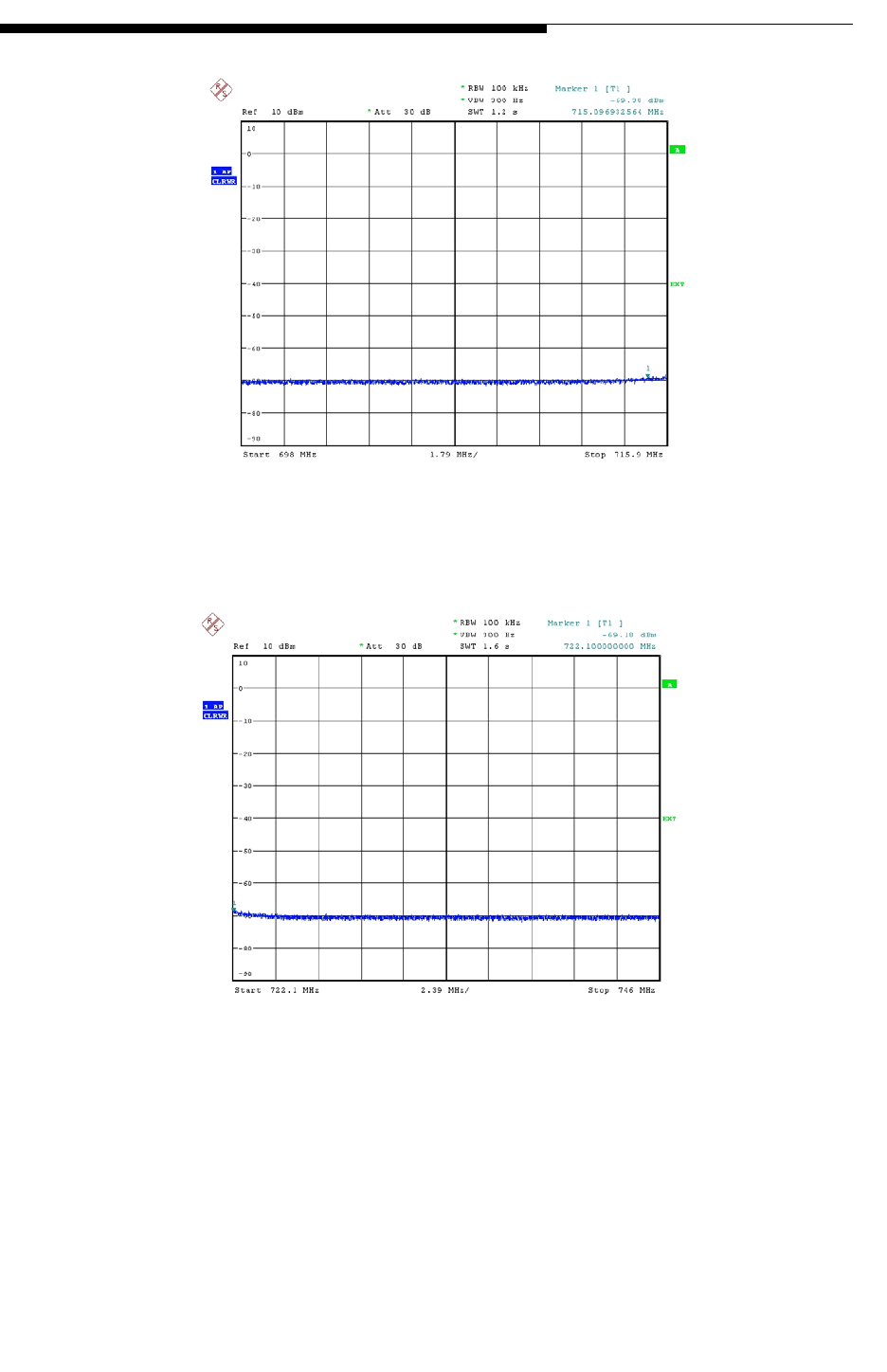
12/24/07 888-2685-001 4-17
WARNING: Disconnect primary power prior to servicing.
Section 4 RF Testing
Ranger Commissioning Manual
Figure 4-4 Out of Band Emissions Plot 1
Figure 4-5 Out of Band Emissions Plot 2
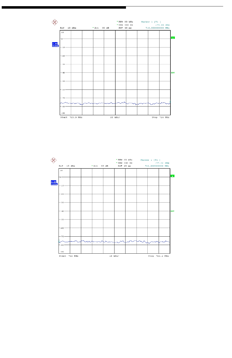
4-18 888-2685-001 12/24/07
WARNING: Disconnect primary power prior to servicing.
Ranger Commissioning Manual
Section 4 RF Testing
Figure 4-6 Out of Band Emissions Plot 3
Figure 4-7 Out of Band Emissions Plot 4
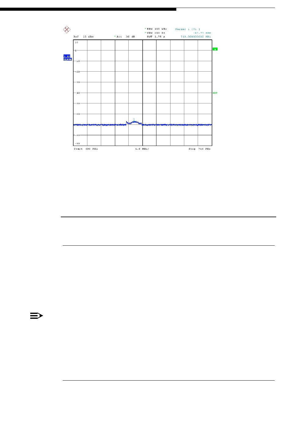
12/24/07 888-2685-001 4-19
WARNING: Disconnect primary power prior to servicing.
Section 4 RF Testing
Ranger Commissioning Manual
Figure 4-8 Out of Band Emissions Plot 5
4.2.14 Spurious Emissions (including 2nd & 3rd harmonics)
4.2.14.1 Objective
To verify the spurious emissions - including 2nd and 3rd harmonics - at the output of
the band pass filter.
The transmitter will be operated in digital mode (FLO modulation) at the nominal rated
RF output power at 719 MHz channel frequency.
NOTE:
The operating frequency of 719 MHz is for U.S. operation. Qualcomm may
define other UHF frequencies for international operation
4.2.14.2 Requirements
See Expected Observation in the procedure below.

4-20 888-2685-001 12/24/07
WARNING: Disconnect primary power prior to servicing.
Ranger Commissioning Manual
Section 4 RF Testing
4.2.14.3 Setup & Test Equipment
Table 4-12 Spurious Emissions Setup
4.2.14.4 Spurious Emissions Procedure
In order to prevent overloading of the spectrum analyzer, a band-reject filter covering
the transmit channel is inserted in front of the analyzer. A high pass filter can be used
instead of a band-reject filter to measure the transmitter harmonics. Connect the
spectrum analyzer to the transmitter band pass filter output forward directional coupler
through the channel band reject filter or the high pass filter as documented.
Transmitter Exciter
Status 1 Active on Exciter A External GPS Active
Status 2 Active on Exciter B External GPS Active
Table 4-13 Spurious Emissions Test Equipment
Spectrum Analyzer
RF Test Cables (with known and measured losses)

12/24/07 888-2685-001 4-21
WARNING: Disconnect primary power prior to servicing.
Section 4 RF Testing
Ranger Commissioning Manual
.
Step Procedure Description Expected Observation
1Configure the transmitter to
operate on air with Exciter A
with precorrector settings to:
Non-Linear Precorrection =
ADAPT
Linear Precorrection = BYPASS
Then connect the spectrum
analyzer to the transmitter band
pass filter output directional
coupler.
2Configure the spectrum analyzer
as follows:
Start Frequency = 746 MHz
Stop Frequency = 824 MHz
Resolution BW = 100 KHz
Video BW = 300 Hz
Sweep = Auto
Sweep Points = 10001
Amplitude Reference Level = 10
dB
Amplitude Attenuation = 30 dB
Then measure 746-824 MHz with
Exciter A on air.
Less than -13dBm/100 kHz
3Change the following spectrum
analyzer settings:
Start Frequency = 824 MHz
Stop Frequency = 894 MHz.
Then measure 824-894 MHz with
Exciter A on air.
Less than -38 dBm/100 kHz
4Change the following spectrum
analyzer settings:
Start Frequency = 894 MHz
Stop Frequency = 1850 MHz.
Then measure 894-1850 MHz
with Exciter A on air.
Less than -13 dBm/100 kHz
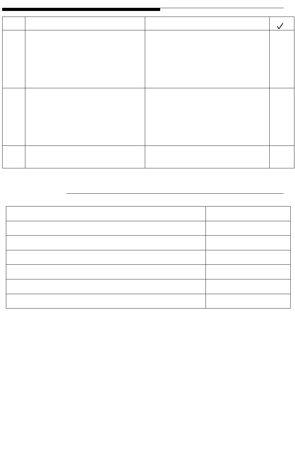
4-22 888-2685-001 12/24/07
WARNING: Disconnect primary power prior to servicing.
Ranger Commissioning Manual
Section 4 RF Testing
4.2.14.5 Spurious Emissions Test Results
The following plots show the typical results:
5Change the following spectrum
analyzer settings:
Start Frequency = 1850 MHz
Stop Frequency = 1990 MHz.
Then measure 1850-1990 MHz
with Exciter A on air.
Less than -38 dBm/100 kHz
6Change the following spectrum
analyzer settings:
Start Frequency = 1900 MHz
Stop Frequency = 3000 MHz.
Then measure 1900-3000 MHz
with Exciter A on air.
Less than -13 dBm/100 kHz
7Repeat steps 2-6 with Exciter B
on air. Results should be consistent with
those from steps 2-6.
Expected results Result
2nd Harmonic with Exciter A PASS FAIL
2nd Harmonic with Exciter B PASS FAIL
3rd Harmonic with Exciter A PASS FAIL
3rd Harmonic with Exciter B PASS FAIL
No emission above limit from 847-3000 MHz with Exciter A PASS FAIL
No emission above limit from 847-3000 MHz with Exciter B PASS FAIL
Step Procedure Description Expected Observation
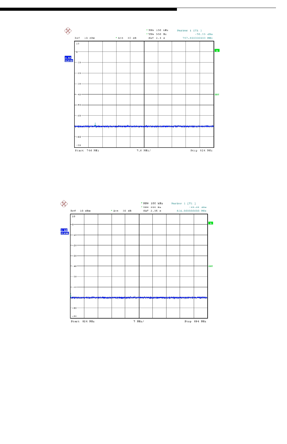
12/24/07 888-2685-001 4-23
WARNING: Disconnect primary power prior to servicing.
Section 4 RF Testing
Ranger Commissioning Manual
Figure 4-9 Spurious Emissions Plot 1
Figure 4-10 Spurious Emissions Plot 2
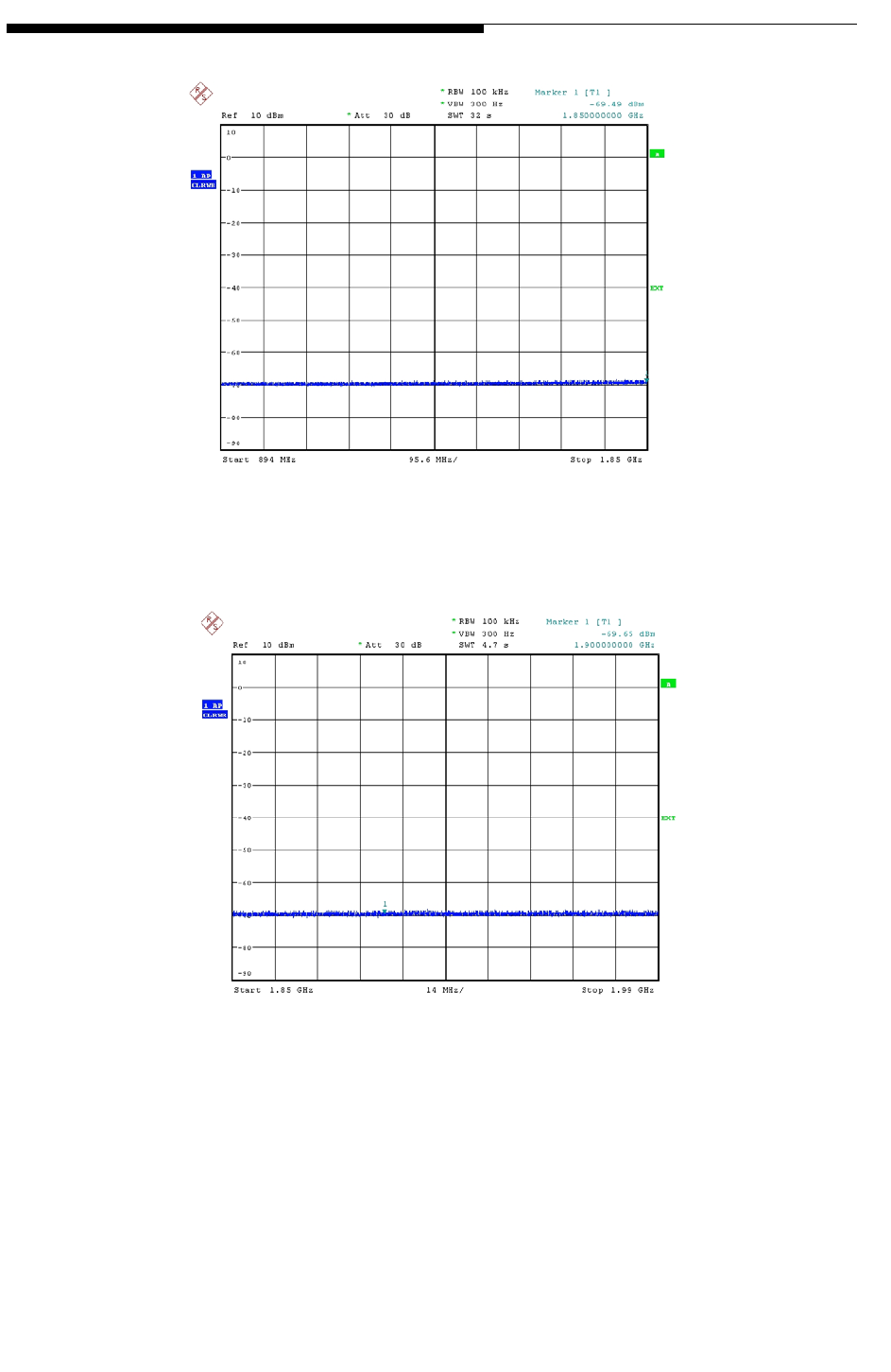
4-24 888-2685-001 12/24/07
WARNING: Disconnect primary power prior to servicing.
Ranger Commissioning Manual
Section 4 RF Testing
Figure 4-11 Spurious Emissions Plot 3
Figure 4-12 Spurious Emissions Plot 4
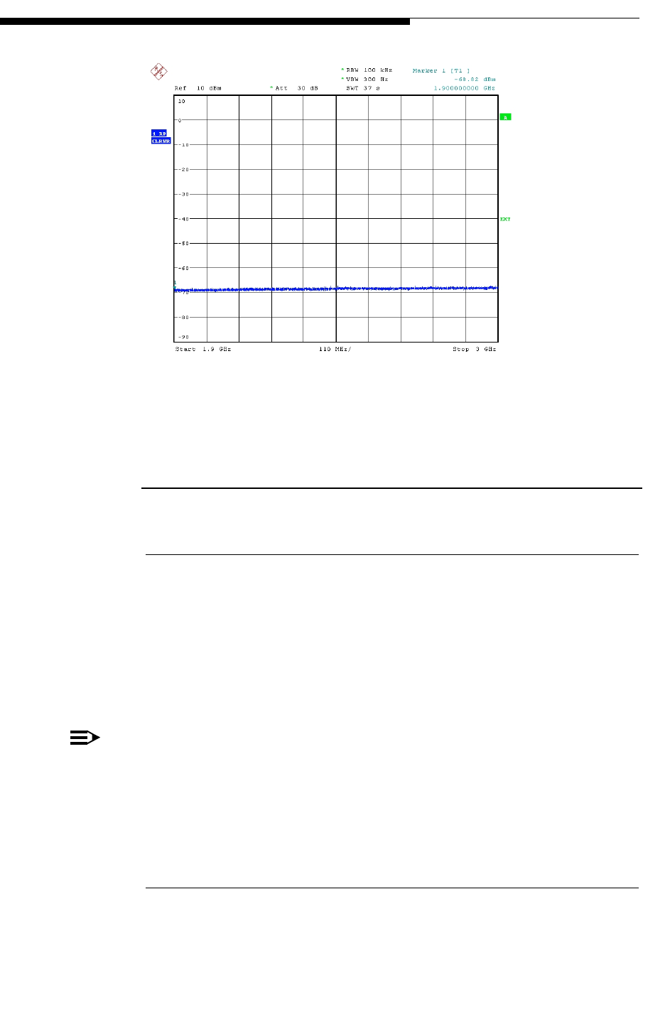
12/24/07 888-2685-001 4-25
WARNING: Disconnect primary power prior to servicing.
Section 4 RF Testing
Ranger Commissioning Manual
Figure 4-13 Spurious Emissions Plot 5
4.2.15 Linear Precorrection (Group Delay & Amplitude
Response)
4.2.15.1 Objective
To verify the linear precorrection - group delay and amplitude response compensation -
at the output of the band pass filter.
The transmitter will be operated in digital mode (FLO modulation) at the rated output
power at the MediaFLO channel frequency. The transmitter output will be connected to
the MediaFLO channel filter assembly terminated in a dummy load.
NOTE:
The transmitter RF must be turned ON at the rated RF output power for at least
four (4) hours to allow for the filter to warm up.
4.2.15.2 Requirements
Group Delay < 1usec
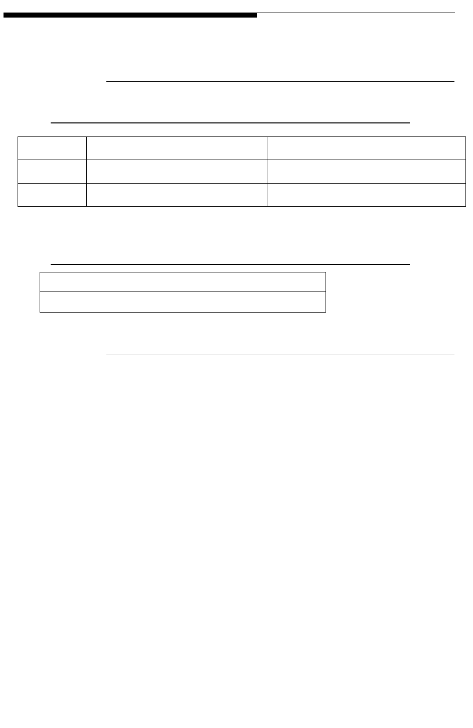
4-26 888-2685-001 12/24/07
WARNING: Disconnect primary power prior to servicing.
Ranger Commissioning Manual
Section 4 RF Testing
Amplitude Response <+/- 0.5 dB
4.2.15.3 Setup & Test Equipment
Table 4-14 Linear Precorrection Setup
4.2.15.4 Spurious Emissions Procedure
In order to prevent overloading of the spectrum analyzer, a band-reject filter covering
the transmit channel is inserted in front of the analyzer. A high pass filter can be used
instead of a band-reject filter to measure the transmitter harmonics. Connect the
spectrum analyzer to the transmitter band pass filter output forward directional coupler
through the channel band reject filter or the high pass filter as documented.
Transmitter Exciter
Status 1 Active on Exciter A External GPS Active
Status 2 Active on Exciter B External GPS Active
Table 4-15 Spurious Emissions Test Equipment
Spectrum Analyzer
RF Test Cables (with known and measured losses)
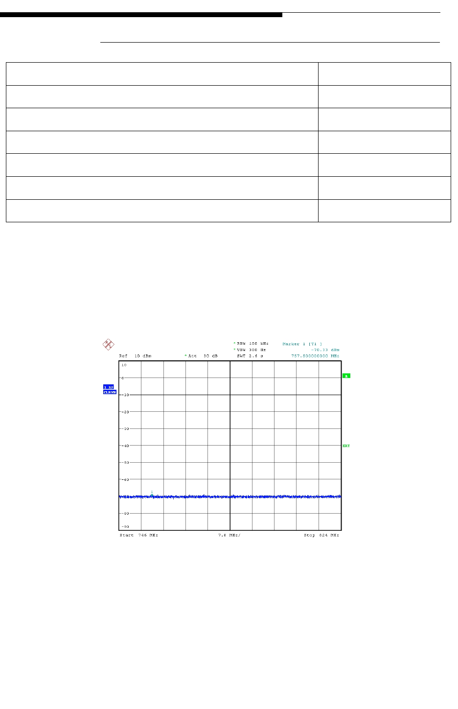
12/24/07 888-2685-001 4-27
WARNING: Disconnect primary power prior to servicing.
Section 4 RF Testing
Ranger Commissioning Manual
4.2.15.5 Spurious Emissions Test Results
The following plots show the typical results:
Figure 4-14 Spurious Emissions Plot 1
Expected results Result (circle)
2nd Harmonic with Exciter A PASS FAIL
2nd Harmonic with Exciter B PASS FAIL
3rd Harmonic with Exciter A PASS FAIL
3rd Harmonic with Exciter B PASS FAIL
No emission above limit from 847-3000 MHz with Exciter A PASS FAIL
No emission above limit from 847-3000 MHz with Exciter B PASS FAIL
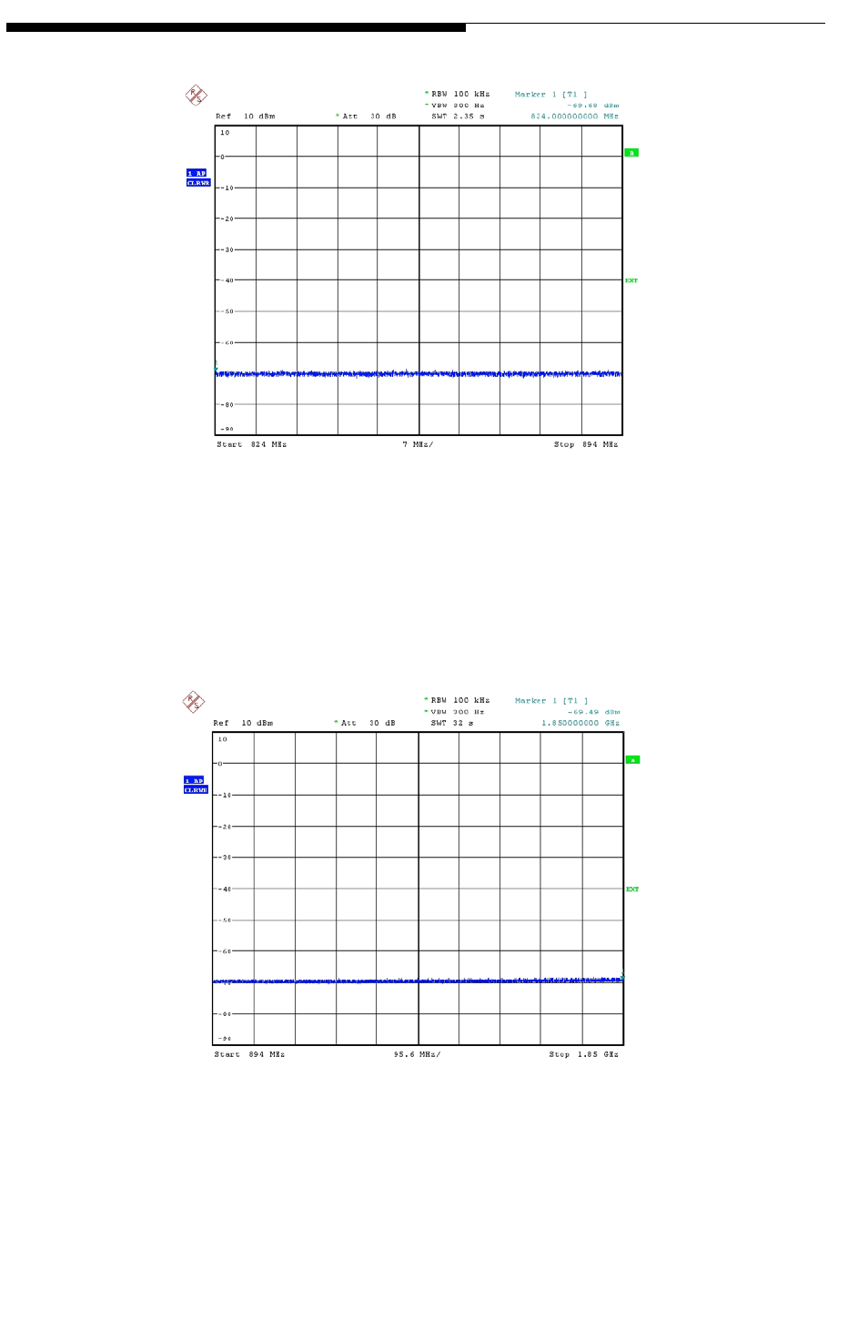
4-28 888-2685-001 12/24/07
WARNING: Disconnect primary power prior to servicing.
Ranger Commissioning Manual
Section 4 RF Testing
Figure 4-15 Spurious Emissions Plot 2
Figure 4-16 Spurious Emissions Plot 3
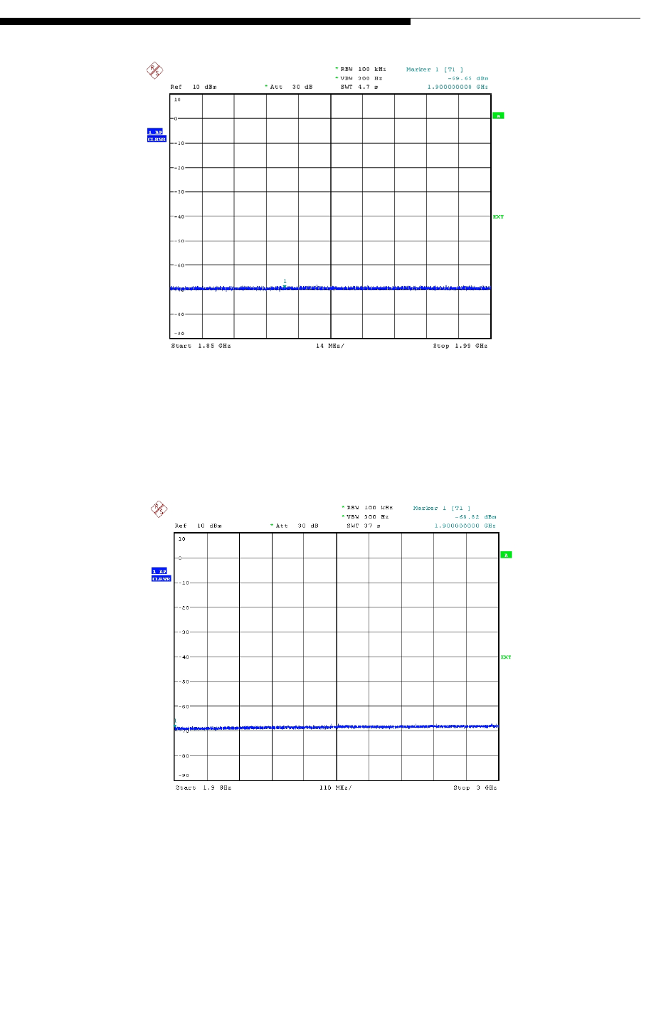
12/24/07 888-2685-001 4-29
WARNING: Disconnect primary power prior to servicing.
Section 4 RF Testing
Ranger Commissioning Manual
Figure 4-17 Spurious Emissions Plot 4
Figure 4-18 Spurious Emissions Plot 5

4-30 888-2685-001 12/24/07
WARNING: Disconnect primary power prior to servicing.
Ranger Commissioning Manual
Section 4 RF Testing
4.2.15.6 Linear Precorrection Procedure
Step Procedure Description Expected
Observation
1Connect the FSQ3 to the transmitter
Mask filter output directional
coupler forward port. The filter
output must be connected to the
dummy load.
NOTE: The transmitter RF must be
turned ON at the rated RF output
power for at least four (4) hours to
allow for the filter to warm up.
2Configure the transmitter to operate
on air with Exciter A with
precorrector settings to:
Non-Linear Precorrection = ADAPT
Linear Precorrection = BYPASS
3Using Katts, transmit test pattern
MER_p2.katts (provided by QC). Let
the PID setting on the transmitter
remain 16. Collect 10 sets of data
after the bandpass filter using the
FSQ test receiver, and compute the
MER.
The MER should be
at least 33dB for all
active subcarriers
4Perform the MER measurement 100
times at the MediaFLO channel filter
assembly output directional coupler
forward port. The MER measurement
procedure also outputs the residual
group delay. Group delay data may
be averaged with 16 sliding averages
in post processing procedure (using
excel).
Residual Group
Delay is less than
1usecs over
Fc+2.71MHz or Fc-
2.71MHz in all the
100 MER
measurements.
5Transmitter turned ON with linear
and non-linear precorrection
performed and turned ON with
Exciter A
Measure the amplitude response.
Amplitude variations
within Fc±2.71MHz
is less than ±0.5dB in
all the 100 MER
measurements.
6Repeat steps 3-5 with Exciter B on
air. Results should be
consistent with those
from steps 3-5.
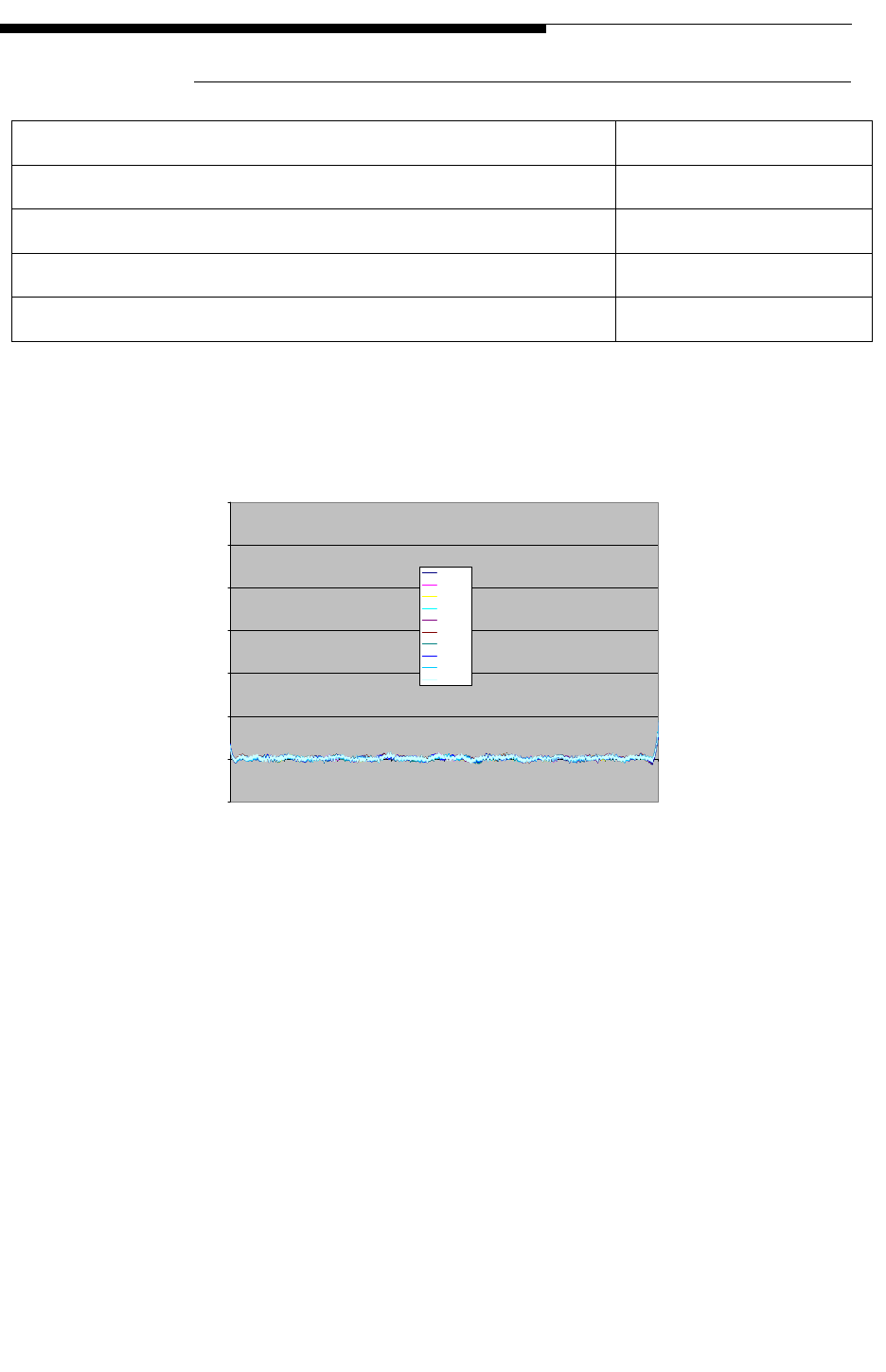
12/24/07 888-2685-001 4-31
WARNING: Disconnect primary power prior to servicing.
Section 4 RF Testing
Ranger Commissioning Manual
4.2.15.7 Linear Precorrection Test Results
The following plots show the typical results:
Figure 4-19 Group Delay Plot 1
Expected results Result
Residual Group Delay < 1 usecs with Exciter A PASS FAIL
Residual Group Delay < 1 usecs with Exciter B PASS FAIL
Amplitude Variations , 1 dB with Exciter A PASS FAIL
Amplitude Variations , 1 dB with Exciter B PASS FAIL
Group delay
-0.5
0
0.5
1
1.5
2
2.5
3
0 500 1000 1500 2000 2500 3000 3500 4000
Channel
Group delay (uS)
Run# 1
Run# 2
Run# 3
Run# 4
Run# 5
Run# 6
Run# 7
Run# 8
Run# 9
Run# 10
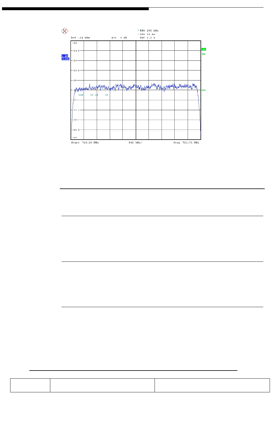
4-32 888-2685-001 12/24/07
WARNING: Disconnect primary power prior to servicing.
Ranger Commissioning Manual
Section 4 RF Testing
Figure 4-20 Amplitude Variation Plot 2
4.2.16 Modulation Error Ratio (MER)
4.2.16.1 Objective
To verify the modulation error ratio (MER) at the output of the band pass filter.
4.2.16.2 Requirement(s)
MER > 33dB
4.2.16.3 Setup and Test Equipment
The Setup and test procedure to measure the MER will be based on the MER Memo
from QUALCOMM in Appendix A.
Table 4-16 Modulation Error Ratio Setup
Exciter Katts

12/24/07 888-2685-001 4-33
WARNING: Disconnect primary power prior to servicing.
Section 4 RF Testing
Ranger Commissioning Manual
Status Active
Set FLO FPGA, SFN mode = OFF
Disable auto-mute
Active, playing configurations speci-
fied in procedure
Table 4-17 Modulation Error Ratio Test Equipment
Per memo provided by Qualcom in Appendix A

4-34 888-2685-001 12/24/07
WARNING: Disconnect primary power prior to servicing.
Ranger Commissioning Manual
Section 4 RF Testing
4.2.16.4 Modulation Error Measurement Procedure
Step Procedure Description Expected
Observation
1Using the controller software,
provision the following set of
parameters:
P = {National Length = 288, Local
Length = 0, PPC Symbols = 14,
Frame Length = 292, WID = 5 and
LID 6, Active TS = TS1, WPID =
LPID = 16, Network Geographic
Delay = 0, Transmitter Delay = 13
microseconds}, and let the exciter be
initialized. Note: WID & LID values
must match the MER tool settings.
Provide the exciter RF output to the
phone over a cable. Precorrection
settings should be set to Non-Linear
Precorrection = Adaptive, Linear
Precorrection = Adaptive
RF Spectrum output
should be clean, and
the phone should
decode the signal
2Set FLO FPGA, SFN mode = Off. Do
not provide any ASI input to the
transmitter
The RF should still
be present
3Collect 10 sets of data after the
bandpass filter using the FSQ test
receiver, and compute the MER as
per Appendix A
The MER should be
at least 33dB for all
active subcarriers
4Using Katts, transmit test pattern
MER_p2.katts (provided by QC). Let
the PID setting on the transmitter
remain 16. Collect 10 sets of data
after the bandpass filter using the
FSQ test receiver, and compute the
MER.
The MER should be
at least 33dB for all
active subcarriers
5Using Katts, transmit test pattern
MER_p3.katts (provided by QC). Let the
PID setting on the transmitter remain 16.
Collect 10 sets of data after the bandpass
filter using the FSQ test receiver, and
compute the MER.
The MER should be at
least 33dB for all active
subcarriers
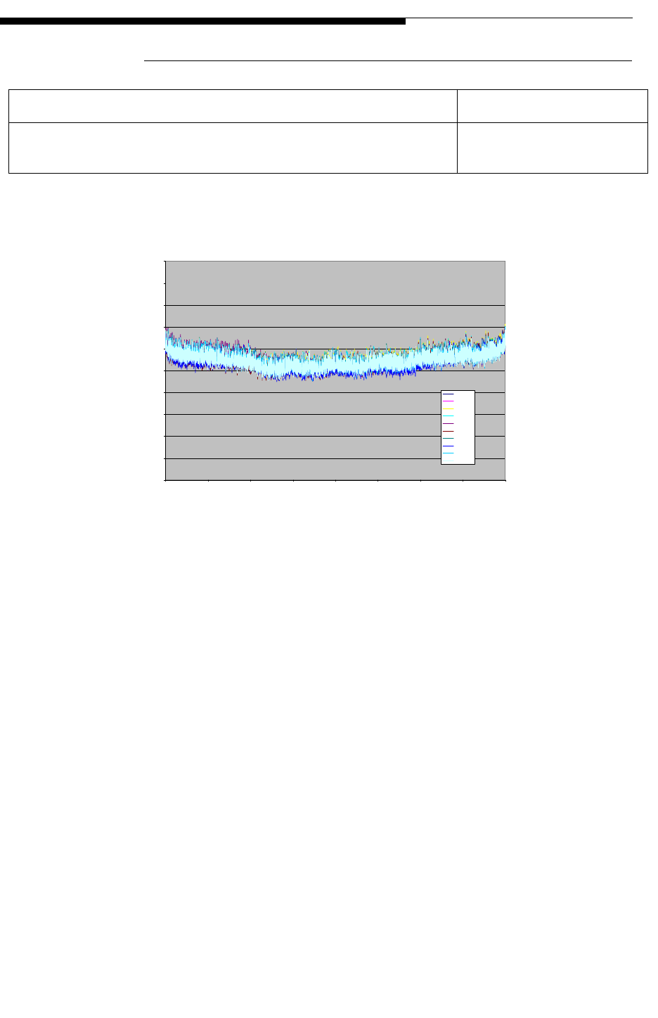
12/24/07 888-2685-001 4-35
WARNING: Disconnect primary power prior to servicing.
Section 4 RF Testing
Ranger Commissioning Manual
4.2.16.5 Modulation Error Results
Figure 4-21 Modulation Error Ration Plot 1
The plot above is the output of Qualcomm’s MER tool. It shows the MER of 10 data
captures (runs).
Expected Results Result (circle)
MER is greater than 33 dB for all the subcarriers in all
the three cases PASS FAIL
MER
30.0000
31.0000
32.0000
33.0000
34.0000
35.0000
36.0000
37.0000
38.0000
39.0000
40.0000
0 500 1000 1500 2000 2500 3000 3500 4000
Channel
MER (dB)
Run# 1
Run# 2
Run# 3
Run# 4
Run# 5
Run# 6
Run# 7
Run# 8
Run# 9
Run# 10
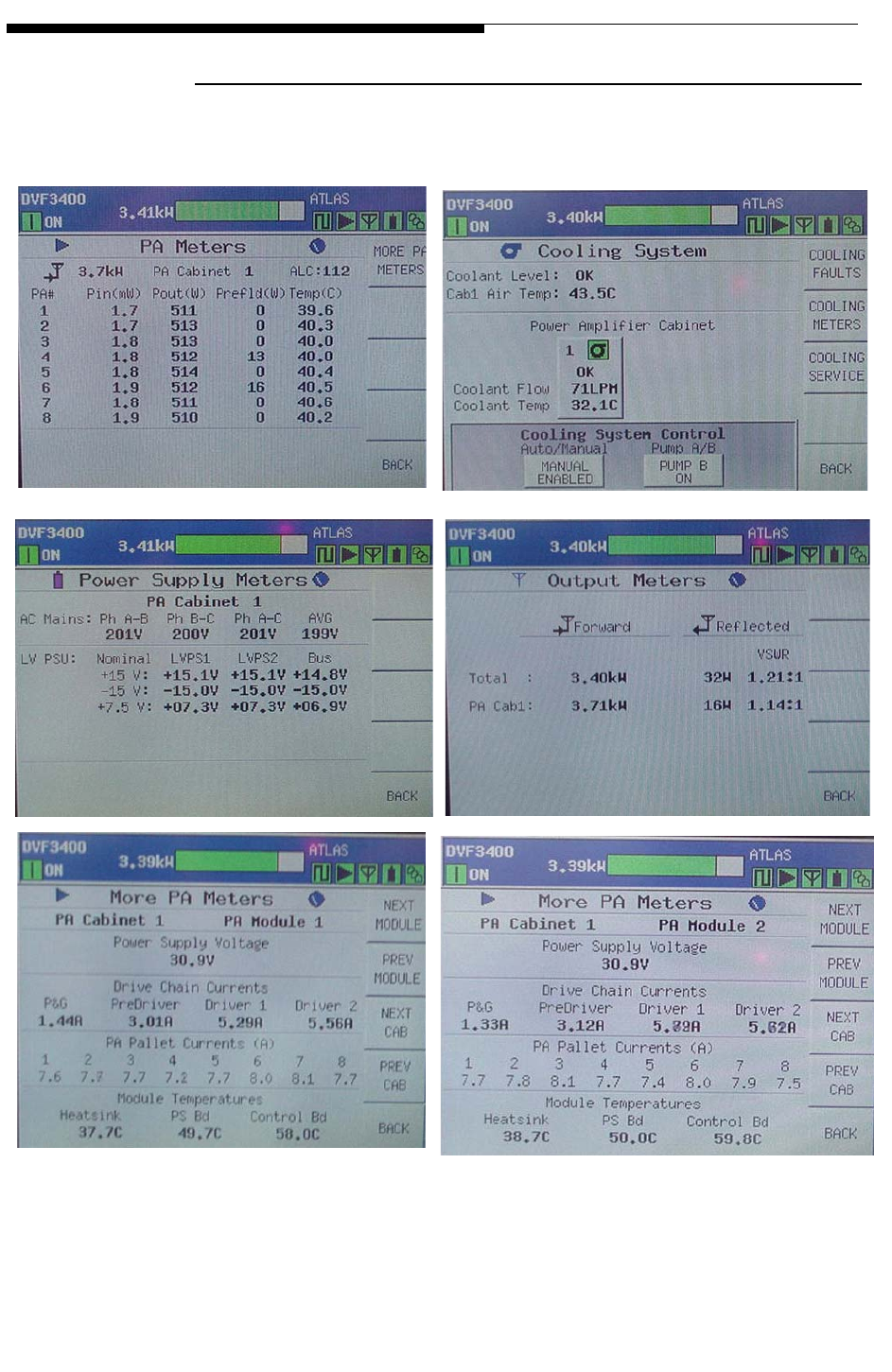
4-36 888-2685-001 12/24/07
WARNING: Disconnect primary power prior to servicing.
Ranger Commissioning Manual
Section 4 RF Testing
4.2.17 Meter Readings
The following GUI screens should be captured or photographed and included in the
report:
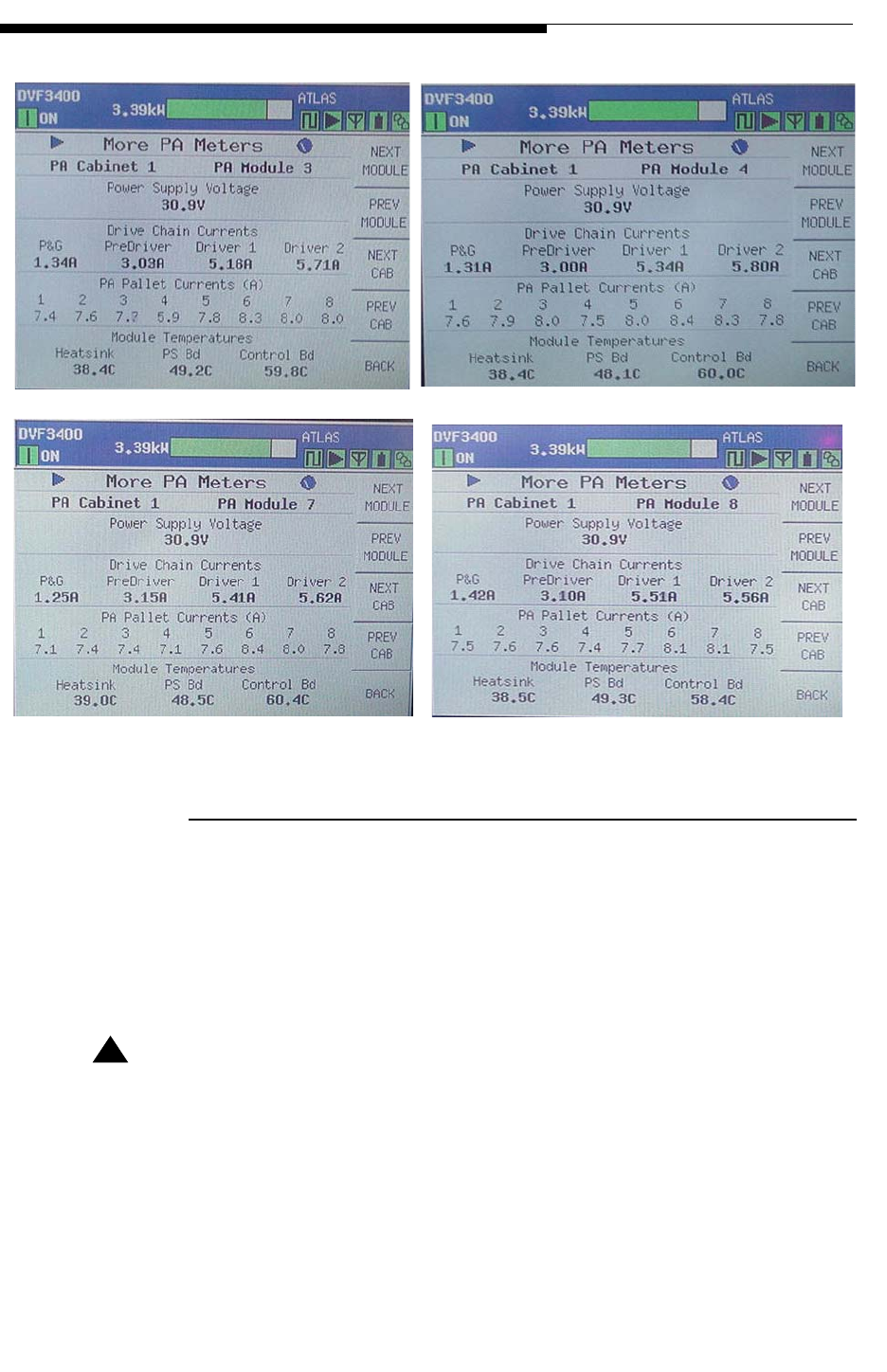
12/24/07 888-2685-001 4-37
WARNING: Disconnect primary power prior to servicing.
Section 4 RF Testing
Ranger Commissioning Manual
4.2.18 System VSWR Plots
The following VSWR plots should be included in the report:
•System VSWR into station load
•System VSWR into transmission line and antenna.
! CAUTION:
PRIOR TO MEASURING THE VSWR OF THE TRANSMISSION LINE AND ANTENNA
MEASURE THE AMOUNT OF RF PRESENT ON THE TRANSMISSION LINE. IN
AREAS OF HIGH RF RADIATION THERE MAY BE ENOUGH RF PRESENT ON THE
TRANSMISSION LINE TO DAMAGE THE INPUT OF THE NETWORK ANALYZER. IN
THESE INSTANCES IT MAY BE NECESSARY TO USE AN AMPLIFIER AT THE
OUTPUT OF THE NETWORK ANALYZER IN ORDER TO GET ACCURATE
MEASUREMENTS.
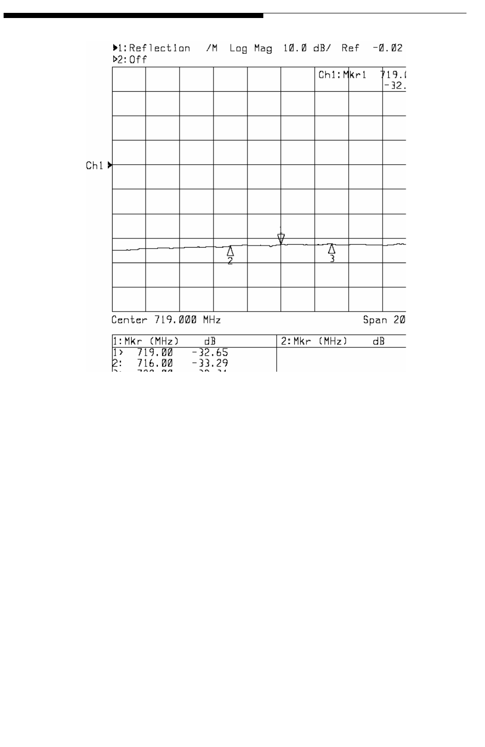
4-38 888-2685-001 12/24/07
WARNING: Disconnect primary power prior to servicing.
Ranger Commissioning Manual
Section 4 RF Testing
Figure 4-22 Station Load Return Loss (sample)
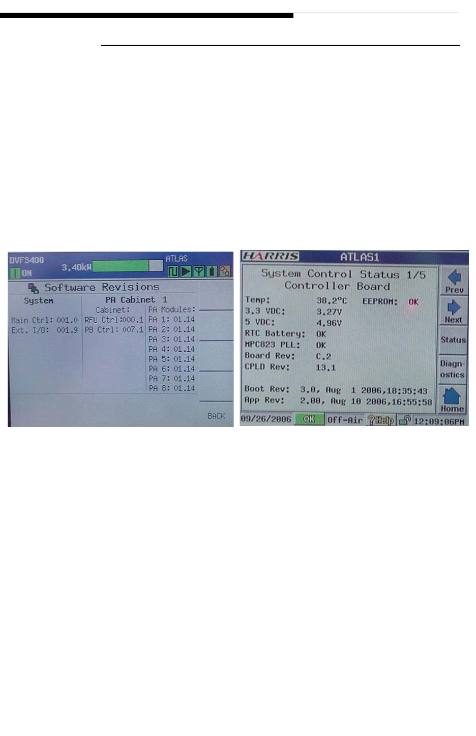
12/24/07 888-2685-001 4-39
WARNING: Disconnect primary power prior to servicing.
Section 4 RF Testing
Ranger Commissioning Manual
4.2.19 Software Versions
•The following GUI screens should be captured on transmitter GUI and the APEX
GUI:
•Software Revisions (Tx GUI sample shown below)
•Adaptive Processing Status (APEX)
•System Control Status Controller 1/5 (APEX sample shown below)
•IF & RF Processing Status UDC Interface Board 1/4 (APEX)
•System Control Status Front Panel Board 4/5 (APEX)
•System Control Status External I/O Board 2/5)
TX GUI APEX

4-40 888-2685-001 12/24/07
WARNING: Disconnect primary power prior to servicing.
Ranger Commissioning Manual
Section 4 RF Testing
4.3 Appendix A - Linux Data Capture & Processing
4.3.1 Introduction
This document is written with the assumption that the “pp” directory has been placed
with the path /local/mnt/pp. In cases where the “pp” directory has been placed with
another path, substitute that path in everywhere this document calls for /local/mnt.
a. In this document a space is indicated by _, an underlined blank character.
b. The “pp” directory contains 4 subdirectories:
1. tracdata: This directory contains files used to capture the I/Q data from the
FSQ.
2. testreceiver: This directory contains files used to process the I/Q data.
3. results: This directory is where the results are stored after processing.
4. automation: This directory contains the shell scripts which run the capture
and processing.
c. The processing main menu discussed later in this document contains the
following 8 choices:
1. Enter “1” to perform the measurement.
2. Enter “2” to change the FLO signal parameters.
3. Enter “3” to view the current FLO signal parameters.
4. Enter “4” to change the Linux computer’s IP address.
5. Enter “5” to view the current Linux computer IP address.
6. Enter “6” to change the setting for the FSQ’s IP address.
7. Enter “7” to view the current setting for the FSQ’s IP address.
8. Enter “8” to exit the processing menu and return to the terminal command
line.
4.3.2 Required Equipment
a. Rhode & Schwarz FSQ
b. Linux Laptop
c. 1PPS source
4.3.3 Block Diagram
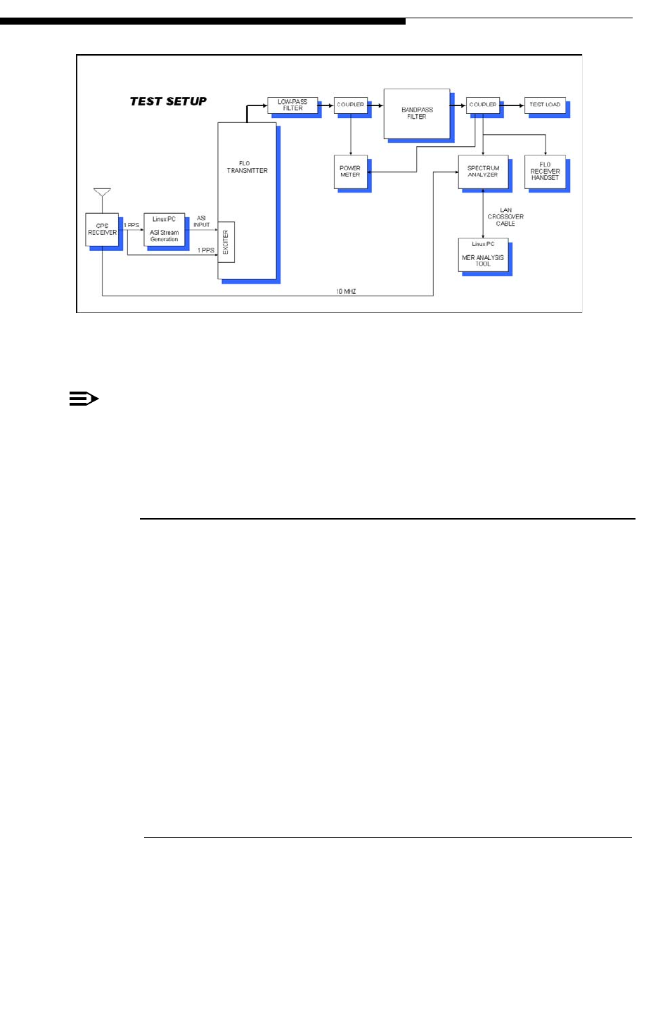
12/24/07 888-2685-001 4-41
WARNING: Disconnect primary power prior to servicing.
Section 4 RF Testing
Ranger Commissioning Manual
Figure 4-23 MER Measurement Block Diagram
NOTE:
This diagram shows the measurement being taken from fwd coupler DC1 of the
filter assembly. If desired the measurement can also be taken from exciter output
and fwd couplers of the transmitter.
4.3.4 1PPS Source Setup
a. The following setup is required when a 1PPS source is not available at the testing
site.
1. Disconnect the GPS RF input from the exciter you are not testing. This is
located on the top of Transmitter rack A.
2. Connect this GPS RF feed to the Synpaq III 1PPS source “ANTENNA”
input.
3. Connect the AC power adapter to the Synpaq III 1PPS source “DC
POWER” input.
4. The Synpaq III “1PPS” output will now be active and will require a Phono-
M to BNC-F adapter.
4.3.4.1 FSQ Connections
a. Connect the FSQ analyzer to an AC source.
b. Connect the 1PPS source to the FSQ rear port labeled “EXT TRIGGER/GATE
IN”.

4-42 888-2685-001 12/24/07
WARNING: Disconnect primary power prior to servicing.
Ranger Commissioning Manual
Section 4 RF Testing
c. Connect an RF cable from the 10MHz monitor port of the exciter under test to the
FSQ rear port labeled ”REF IN 1…20MHz”.
d. Connect an Ethernet crossover cable between the LAN interface on the rear of the
FSQ and the Linux laptop.
e. Connect an RF cable from the filter assembly desired measurement port to the
FSQ front port labeled “RF INPUT”.
NOTE:
The power level into the FSQ should be -27dBm ± 1dBm. Measure the input feed
power level with a power meter and adjust the level with attenuators as needed to
get as close as possible to -27dBm.

12/24/07 888-2685-001 4-43
WARNING: Disconnect primary power prior to servicing.
Section 4 RF Testing
Ranger Commissioning Manual
4.3.4.2 FSQ Settings
a. Press the “PRESET” key to restore the FSQ default state.
b. Recall the “DATA_CAPTURE” state from the FSQ:
1. Press the “FILE” key on the FSQ
2. Press the “RECALL” softkey on the FSQ
3. Select the path to the disk where the state is saved.
4. Select “DATA_CAPTURE” and select “OK”
5. Verify the following:
a. Press “SETUP” key and verify “REFERENCE” is set to “EXT”
b. RBW = 30kHz
c. VBW = 300Hz
d. Attn = 5dB
e. Ref Lev = -20dBm
f. Press “TRIG” key and verify the “EXTERN” softkey is selected.
c. If the FSQ “DATA_CAPTURE” state is not available:
1. Press the “SETUP” key and then use “REFERENCE” softkey to set to
EXT.
2. Press the “FREQ” key and enter the desired center frequency using the
number pad and unit selections.
3. Press the “SPAN” key and enter “10” from the numeric keypad and
terminate the entry with the “MHz” key.
4. Press the “BW” key. Press the “RES BW MANUAL” softkey and enter
“30 kHz”. Then press the “VIDEO BW MANUAL” softkey and enter
“300 Hz”.
5. Press the “TRIG” key and then press the “EXTERN” softkey.
4.3.5 Setting Static IP Address for FSQ & Linux Machine
Connect an Ethernet crossover cable between the LAN interface on the rear of the FSQ
and the Linux laptop.

4-44 888-2685-001 12/24/07
WARNING: Disconnect primary power prior to servicing.
Ranger Commissioning Manual
Section 4 RF Testing
4.3.5.1 For the FSQ
a. Press the “SETUP” key. Press the “GENERAL SETUP” soft key and then the
“CONFIGURE NETWORK” softkey.
b. Using the arrow keys or knob, select the desired Local Area Connection and the
press the enter key.
c. The LAN status dialog box appears, select “Properties” and press enter.
d. Using the arrow keys select “Internet Protocol (TCP/IP)”, and then use the knob
to select properties and press enter.
e. Enter an IP address and Subnet mask. The following is suggested:
1. IP address: 10.46.252.190
2. Subnet mask: 255.255.255.0
4.3.5.2 For Linux Laptop
a. Log on to Linux laptop
1. Username: root
2. Password: M3diaFL0
b. Open a new terminal by right clicking on the desktop and selecting “New
Terminal” from the drop down menu.
c. Go to the processing main menu by typing:
1. cd_/local/mnt/pp/automation
2. ./PROCESSING
d. Change the Linux machines settings for the FSQ’s IP address.
1. Enter “6” and press “ENTER”.
2. Enter the static IP address which was set for the FSQ. The suggested FSQ
IP address is 10.46.252.190
e. Set the Linux machine to have a static IP address similar to the FSQ:
1. Enter “4” and press “ENTER”.
2. Enter “1” and press “ENTER”.
3. Enter the IP address and press “ENTER”. The suggested IP address is
10.46.252.189
4. Enter the subnet mask and press “ENTER”. The suggested subnet mask is
255.255.255.0

12/24/07 888-2685-001 4-45
WARNING: Disconnect primary power prior to servicing.
Section 4 RF Testing
Ranger Commissioning Manual
f. To verify the connection with the FSQ:
1. Open a new terminal by right clicking on the desktop and selecting “New
Terminal” from the drop down menu.
2. In the terminal type “ping xxx.xxx.xxx.xxx” where the x’s represent the
FSQ’s IP address. After pressing enter the screen should display that the
ping was returned with 0% loss. After a few lines have progressed with 0%
loss press “CTRL+C” to stop the ping.
4.3.6 Capturing and Processing Data
4.3.6.1 Setting Flo Signal Parameters
The FLO signal parameters must be correct for each site in order to ensure accurate
results. Once the FLO signal parameters are set through they do not need to be changed
until there is a change in the FLO signal.
a. Log on to Linux laptop
1. Username: root
2. Password: M3diaFL0
b. Open a new terminal by right clicking on the desktop and selecting “New
Terminal” from the drop down menu.
c. Go to the processing main menu by typing:
1. cd_/local/mnt/pp/automation
2. ./PROCESSING
d. Changing the FLO signal Parameters:
1. Enter “2” and press “ENTER”.
2. Enter the WID and press “ENTER”.
3. Enter the LID and press “ENTER”.
4. Enter the # of OFDM symbols per frame and press “ENTER”.
5. Enter the # of reserved symbols (PPC) and press “ENTER”.
6. Enter the first local symbol and press “ENTER”. The first local symbol is
equal to the national length +2.

4-46 888-2685-001 12/24/07
WARNING: Disconnect primary power prior to servicing.
Ranger Commissioning Manual
Section 4 RF Testing
4.3.6.2 Performing the Measurement
a. Open a new terminal by right clicking on the desktop and selecting “New Termi-
nal” from the drop down menu.
b. Go to the processing main menu by typing:
1. cd_/local/mnt/pp/automation
2. ./PROCESSING
c. If the FLO signal parameters have changed since the last capture change the
settings for FLO signal parameters.
d. Perform the measurements
1. Enter “1” and press “ENTER”.
2. Enter the desired number of captures and press “ENTER”.
4.3.6.3 Looking at the Results
a. Open a new terminal by right clicking on the desktop and selecting “New Termi-
nal” from the drop down menu.
b. The results are stored in a directory indexed by data and time
c. Go to the results directory
1. cd_/local/mnt/pp/results
d. Go to the indexed directory for the day, month, year of the desired capture
1. ls -- To list the possible directories
2. cd_ddMMYYYY
e. Go to the indexed directory for the hour, minute, second of the desired capture
1. ls -- To list the possible directories
2. cd_HHMMSS
f. Open a file to view its contents
1. ls -- To view the files in the directory
2. emacs_filename
4.3.6.4 Moving Results to Flash Drive
a. Mounting the flash drive

12/24/07 888-2685-001 4-47
WARNING: Disconnect primary power prior to servicing.
Section 4 RF Testing
Ranger Commissioning Manual
1. Click on the “RedHat” icon on the taskbar.
2. Select “System Tools”
3. Select “Disk Management”
4. In the user mount tool, select the directory /mnt/flash and click “Mount”
b. Open a new terminal by right clicking on the desktop and selecting “New
Terminal” from the drop down menu.
c. Go to the indexed directory for the day, month, year of the desired capture
1. cd_/local/mnt/pp/results/ddMMYYYY
2. ls -- To view the possible results in the directory
d. Copy the desired result directory to the flash drive
1. cp_-rf_HHMMSS/_/mnt/flash
e. Unmounting the flash drive
1. Click on the “RedHat” icon on the taskbar.
2. Select “System Tools”
3. Select “Disk Management”
4. In the user mount tool, select the directory /mnt/flash and click “Unmount”

4-48 888-2685-001 12/24/07
WARNING: Disconnect primary power prior to servicing.
Ranger Commissioning Manual
Section 4 RF Testing
4.4 Appendix B - Generating a CW Tone
a. Open a web browser and enter the IP address of the eCDi with the target exciter
port.
1. http://eCDI's IP:20080 exciter AAdd: Steps 1, 2 & 3.
2. http://eCDI's IP:20180 exciter B
3. (API Test Configuration Register 1)
4. "Request Memory File"
5. Memory Start Address: 40000C8
6. Memory Length: 1
7. This will be used to verify the current value.
8. Go to "Upload/Execute FPGA Script File" and upload the script file
"CWEnable.txt"
9. Script "CWDisable.txt” will disable the tone once testing is completed.
b. CW enable script
1. n
2. # Script file for testing FPGA Modulator board
3. # m <address> <count> <cr>- dump data command; dumps "count" 32-bit
words at <address>
4. # l <address> <count> <data> <cr>- fill same data command; fills "count"
32-bit words with data starting at <address>
5. # p <address> <count> <d(n) d(n+1)... d(count)> <cr> - fill data
command; fills "count" 32-bit words data(n) to data(count) starting at
<address>
6. # k <address> <cr>- peek address command; reads 32-bit data word at
<address>
7. # o <address> <data> <cr>- poke data command; writes 32-bit data word
at <address>
8. # h <cr>- echo on command - enables echo of command file to log file
9. # n <cr>- echo off command - disables echo of command file to log file
10. # w <cr>- wait for 10 msec.
11. # z - END FILE: z
12. h
13. # enable cw tone IQ_MUX_ATT
c. CW disable script

12/24/07 888-2685-001 4-49
WARNING: Disconnect primary power prior to servicing.
Section 4 RF Testing
Ranger Commissioning Manual
1. n
2. # Script file for testing FPGA Modulator board
3. # m <address> <count> <cr>- dump data command; dumps "count" 32-bit
words at <address>
4. # l <address> <count> <data> <cr>- fill same data command; fills "count"
32-bit words with data starting at <address>
5. # p <address> <count> <d(n) d(n+1)... d(count)> <cr> - fill data
command; fills "count" 32-bit words data(n) to data(count) starting at
<address>
6. # k <address> <cr>- peek address command; reads 32-bit data word at
<address>
7. # o <address> <data> <cr>- poke data command; writes 32-bit data word
at <address>
8. # h <cr>- echo on command - enables echo of command file to log file
9. # n <cr>- echo off command - disables echo of command file to log file
10. # w <cr>- wait for 10 msec.
11. # z - END FILE: z
12. h
13. # disable cw tone IQ_MUX_ATT

4-50 888-2685-001 12/24/07
WARNING: Disconnect primary power prior to servicing.
Ranger Commissioning Manual
Section 4 RF Testing
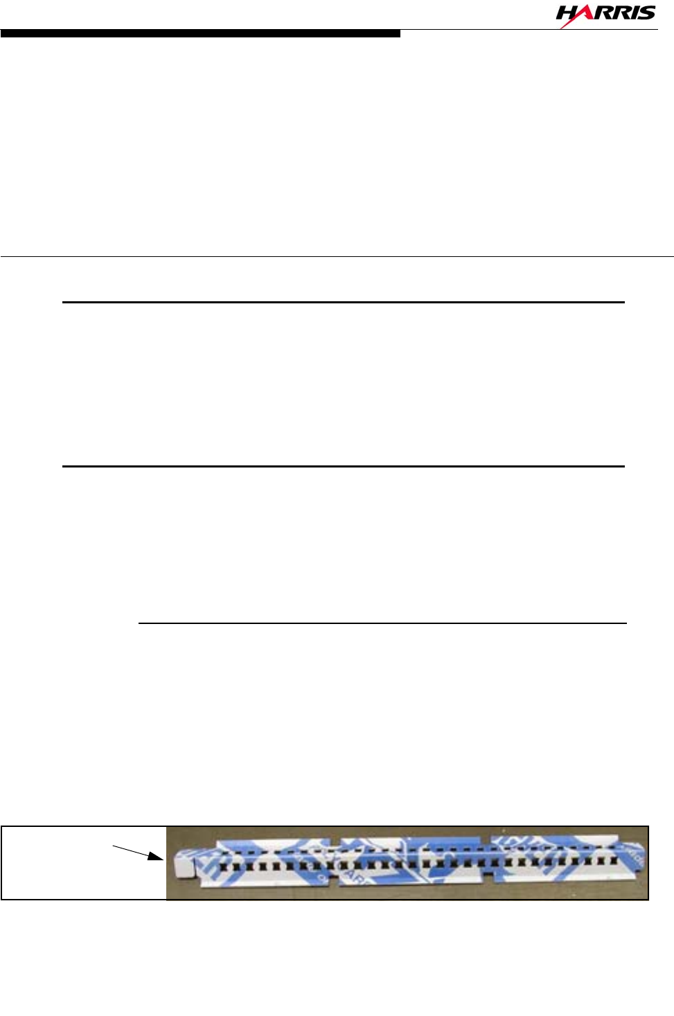
12/24/07 888-2685-001 5-1
WARNING: Disconnect primary power prior to servicing.
Ranger Commissioning Manual
Section 5
Replacement
Procedures 5
5.1 Introduction
This section contains information on how to remove and replace electrical and
mechanical parts and any alignments or adjustments associated with the replacement.
All routine alignment procedures are contained in Section 3 with the associated GUI
screen.
5.2 PA Module Removal
The PA module(s) simply push in or pull out of the transmitter. There are no latches or
screws. There is a module off switch located behind the front cover at the top and
bottom of the module so that when the module is grasped to be pulled out, the touch
switch shuts it off first.
5.2.1 CZ1000F PA Module Air Block
For the CZ1000F, a special Air Block (a long, thin Lexan shield shown in Figure 5-1)
has been provided in case one of the modules is to be removed for an extended period of
time. The Air Block simulates the back pressure of a module. This keeps the airflow
through the rest of the transmitter at normal levels even with the module removed. The
Air Block will only fit in Slot #2 (the right-hand slot). Therefore, if a module is to be
removed for a period of more than a few hours, the Air Block should be installed in slot
2 and the remaining module must be placed in slot 1 (if not already there).
Figure 5-1 Lexan Air Block
Install this end
nearest the back
of the cabinet
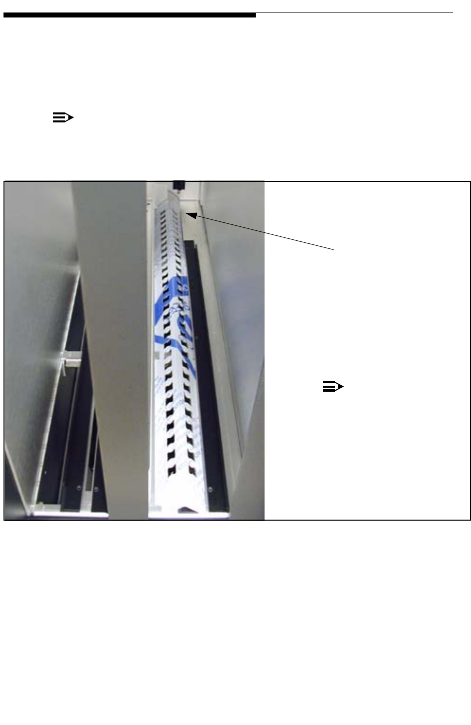
5-2 888-2685-001 12/24/07
WARNING: Disconnect primary power prior to servicing.
Ranger Commissioning Manual
Section 5 Replacement Procedures
To install the Air Block, place the right side into the slot as shown in Figure 5-2. To
finish, squeeze near the back until it starts into the slot on the left. Now using either
your hands or a screwdriver, work it into the slot from back to front. It could also be
installed starting at the front and working your way to the back, whichever works best
for you. When finished, both sides of the Air Block should be captive under the shelf.
NOTE:
If you use a tool to aid installation, be very careful not to bend the aluminum
guide to the left of the slot.
Figure 5-2 Air Block Installed
NOTE:
The peelable label was left on
the lexan so that the pictures
would show up better. The label
should be peeled off before use.
Note: The slot is installed around
the aluminum bracket.
12/24/07 888-2685-001 5-3
WARNING: Disconnect primary power prior to servicing.
Section 5 Replacement Procedures
Ranger Commissioning Manual
5.2.2 PA Module Pallet Replacement
The phase and gain of the individual pallet amplifiers in the PA Module are tightly
controlled in manufacturing allowing field replacement of the individual pallets using a
"PA Pallet Replacement Kit". The PA Modules are designed to cover a specific
frequency range or BAND within the UHF DTV spectrum. The PA Modules for each
band have a different part number and so do the Pallet Replacement Kits. See Table 5-1.
The tools required for the replacement include:
•Safety glasses
•Soldering iron
•Sn63Pb37 solder (Harris Part# 086-0004-054)
•Alcohol and a piece of cotton cloth
•Medium size Phillips blade screwdriver
•Medium size flat blade screwdriver
•7/64" size Allen wrench with torque indicating mechanism (15 inch pounds)
The Pallet replacement procedure is as described below:
! WARNING:
THE DIAMOND PA MODULES ARE DESIGNED TO HANDLE VERY HIGH TEMPERA-
TURES AND MAY BE EXTREMELY HOT, UP TO 90O F (50O C) ABOVE ROOM TEM-
PERATURE. DO NOT TOUCH THE MODULES WITH BARE HANDS AFTER THE
TRANSMITTER HAS BEEN RUNNING, ESPECIALLY IN HIGH AMBIENT TEMPERA-
TURE ENVIRONMENTS. SPECIAL GLOVES HAVE BEEN PROVIDED IN THE REAR
OF THE CONTROL CABINET OR CAN BE OBTAINED FROM HARRIS, PART #099-
0006-483 OR GRAINGER ITEM #4JF36.
STEP 1 Using the protective gloves, remove the PA module from the
Transmitter.
STEP 2 Place the module on the bench with the lid up.
STEP 3 Remove the cover using the Phillips screwdriver to remove all the screws.
Table 5-1 PA Pallet Replacement Kit Part Numbers
Replacement Kit Part # Channels (Frequency Band)
994-9782-002 42 - 58 (636 - 741MHz)
994-9782-003 59 - 78 (736 - 860MHz)
994-9782-004 14 - 26 (470 - 550MHz)
994-9782-005 27 - 41 (547 - 638MHz)
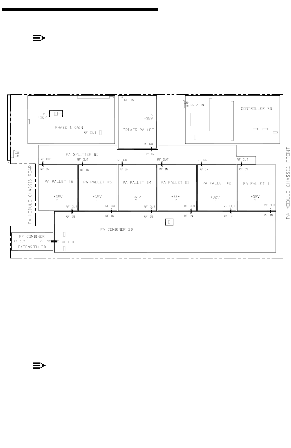
5-4 888-2685-001 12/24/07
WARNING: Disconnect primary power prior to servicing.
Ranger Commissioning Manual
Section 5 Replacement Procedures
STEP 4 Unsolder the brown DC power wire from the bad pallet, and stretch it up.
NOTE:
Be sure to properly identify the failed pallet prior to removal. Figure 5-3 can be
used to verify pallet location. The pallets are numbered 1 through 6 with pallet
number 1 being closest to the front of the module.
Figure 5-3 PA Pallet Numbering Scheme
STEP 5 Unsolder the input and output ribbon wires from the pallet side leaving
them attached on the combiner and splitter. Carefully bend them up and
out of the way. Remove the 7 Allen head mounting screws holding the
pallet in place.
STEP 6 Carefully lift up the pallet using the copper clamps, situated over the RF
Transistors as handles.
NOTE:
Lifting the pallet can be made easier by using a flat blade screwdriver to gently
pry upward on the edge of one of the screws still mounted to the pallet being
removed. Use an adjacent screw on an adjacent board to pry against lifting up on
the board that is being removed. Once the board is loosened in this way the cop-

12/24/07 888-2685-001 5-5
WARNING: Disconnect primary power prior to servicing.
Section 5 Replacement Procedures
Ranger Commissioning Manual
per clamps can be used to finish removal of the board with less pressure
required.
STEP 7 Remove the thermal pad from the heat sink and discard. These pads
should not be reused.
STEP 8 Wipe off any thermal grease or other residue from the heat sink using the
cotton cloth and alcohol. Make sure the surface is completely clean in
preparation for the installation of the new pallet.
STEP 9 Install the new thermal pad. The pad is oriented so the brown wire is
passed through the hole as the pad is installed on top of the heat sink. It
does not matter which side of the thermal pad is up and which side is
down as there is no performance difference.
STEP 10 Position the new PA pallet in place with the brown wire directed through
the corresponding hole in the pallet.
STEP 11 After the pallet is placed, make sure the DC power wire passing
underneath the pallet is entirely inside of the designated channel in the
heat sink and is not between the pallet and the heat sink.
STEP 12 Install the seven mounting screws and torque each to 15 inch pounds.
STEP 13 Solder the brown DC power wire onto the newly installed pallet using
the soldering iron and Sn63Pb37 solder.
STEP 14 Use an Ohmmeter to check the resistance from the brown power wire
pad to ground. It should be 1K ohm or greater. If the meter shows a short
circuit or low Ohm reading between these two points, remove the pallet,
and check the wire position underneath the pallet. Fix the position of the
wire and re-mount the pallet.
STEP 15 Solder the input and output ribbon wires to the pallet, make sure the
ribbon wire is not broken, damaged, or touching ground at any point.
STEP 16 Clean all three solder connections with a piece of cotton cloth and
alcohol.
STEP 17 Replace the lid on the module and reinstall all the screws.
Install the module back into the transmitter and push the ON button, check the value of
the DC current consumed by the new pallet. It should be the same as for the rest of the
pallets +/- 10%.
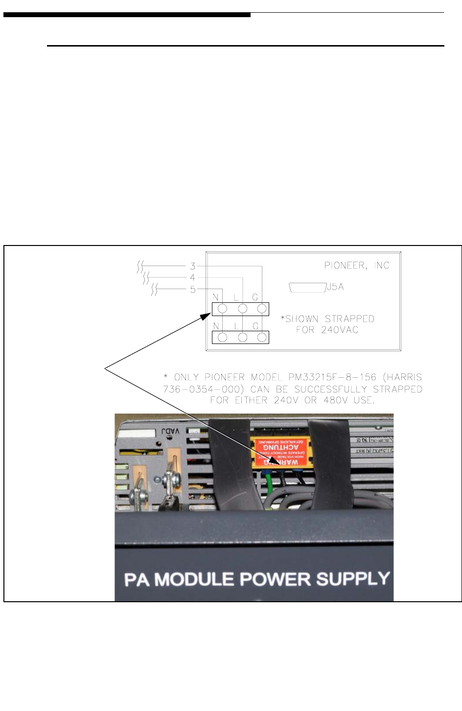
5-6 888-2685-001 12/24/07
WARNING: Disconnect primary power prior to servicing.
Ranger Commissioning Manual
Section 5 Replacement Procedures
5.3 Power Supply Module Replacement
Removal and replacement of the power supply module is a simple matter of shutting off
the breaker on the front of the module, removing the 2 black screws in the front panel
and pulling the module out.
Before replacing the module with a new one be sure to check the AC voltage strapping
on the front side of the supply (inside the aluminum chassis). The power supply
modules can be strapped for 240 or 480 Vac but all Ranger supplies should be strapped
for 240 Vac operation. Proper strapping for 240Vac is shown in Figure 5-4, along with a
picture of the inside of the actual supply chassis. This information (and 480Vac
strapping) is also shown on the Power Supply Wiring Diagram, 843-5494-353 in the
schematic package.
Figure 5-4 Power Supply AC Strapping
Jumpers should be
straight across
between the
terminal strips as
shown here
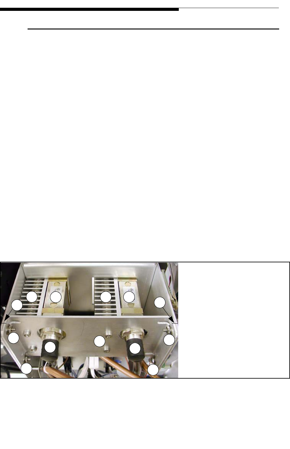
12/24/07 888-2685-001 5-7
WARNING: Disconnect primary power prior to servicing.
Section 5 Replacement Procedures
Ranger Commissioning Manual
5.4 Circulator Removal/Replacement
The circulators are mounted on an adjustable plate behind the PA modules. It is very
important that when they are replaced that they are mounted correctly or the module
may not seat properly in the circulator. If mounted too far forward, the circulator could
actually hold the module out so that it does not seat properly in the lower module
connector which carries PS, signal and control causing the module not to operate or
become intermittent.
STEP 1 Shut the transmitter off along with the breaker on the power supply.
STEP 2 Pull the PA modules out a few inches to disengage them from the rear
connectors.
STEP 3 Mark the adjustable plate shown in Figure 5-5 for front to back position
(F) on the top as shown and on the bottom. This will make re-assembly
much easier and increase confidence that it is back in the correct
position.
STEP 4 Remove the RF output cables (D) and the reject cables from the
circulators. If necessary, mark them for proper installation later.
STEP 5 Remove the adjustable plate screws (C) and pull circulator assembly
straight back. This should provide access to the screws on the side of
either circulator. The heatsink screws pass all the way through the
heatsink and should only be removed if better access to the circulator
screws is required.
Figure 5-5 Circulator Assembly
AB
C
CC
C
D
A
B
D
A - Circulator
B - Circulator Heatsink
C - Adjustable plate screw
s
D - RF Output Cables
E - Heatsink screws
E
F - Mark plate here
F
F
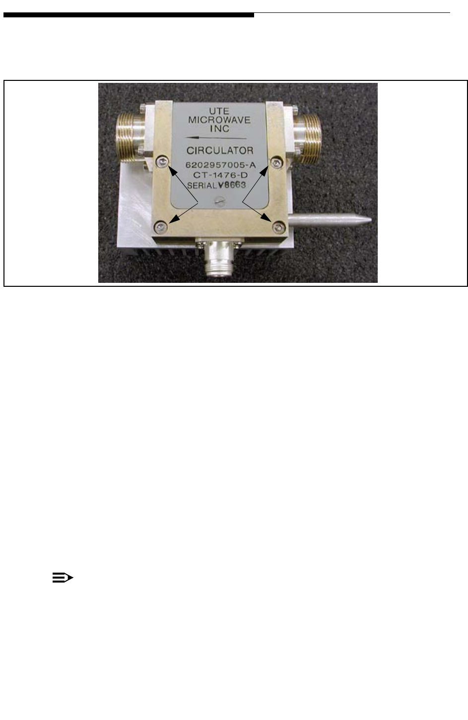
5-8 888-2685-001 12/24/07
WARNING: Disconnect primary power prior to servicing.
Ranger Commissioning Manual
Section 5 Replacement Procedures
STEP 6 The circulator screws are hex head and require an allen tool to remove.
These screws are shown in Figure 5-6.
Figure 5-6 Circulator Side View
STEP 7 Clean the old thermal compound off of the heatsink with cotton cloth
and alcohol. Put a thin layer of thermal compound on the new circulator
and mount it to the heatsink.
STEP 8 Push the modules back into place. Have someone hold the modules
firmly in place or tape them to the cabinet for the next step.
STEP 9 Re-install the adjustable plate with the circulators mounted on it. With
the modules held in place, seat the circulators into the module. The
marks you made earlier should be very close to lining up. They should
not be any further away from the module than before. The most
important thing is that you are not holding the module away from the
lower connector but are making good RF contact to the circulator.
STEP 10 Tighten the screws (C) in the adjustable plate and then re-connect the RF
output and reject cables to the circulators. Make sure you connect the
cables to the same circulator as before.
NOTE:
Swapping the output cables will cause all of the power to end up in the combiner
reject load, while swapping the reject cables will cause the attenuator readings to
be reversed on the GUI and therefore protect the wrong attenuator.
It should not be necessary but you may want to check module phasing and adjust if
necessary for the CZ1000F, see "3.7.2 Module Phasing Procedure" on page 3-18.
Remove
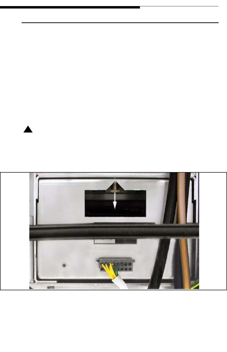
12/24/07 888-2685-001 5-9
WARNING: Disconnect primary power prior to servicing.
Section 5 Replacement Procedures
Ranger Commissioning Manual
5.5 Blower Assembly Removal
The blower assembly is a slide-in unit which can be removed as follows:
(See Figure 5-7)
• Shut the transmitter off.
• Remove the horizontal divider plate directly behind the blower assembly.
• Disconnect the blower power connector at the back of the blower assembly.
• Pull down on the spring loaded locking pin at the back of the assembly and
pull the blower assembly out the back of the cabinet. It may be necessary to
move some cable out of the way. Be careful not to over-extend any of the
smaller cables.
! WARNING:
DO NOT LEAVE THE DIVIDER PLATE OUT DURING RE-ASSEMBLY. THE DIVIDER
PLATE IS NECESSARY FOR PROPER TRANSMITTER AIRFLOW AND COOLING.
Figure 5-7 Blower Tray, Rear View
Pull Pin Down to Remove
Horizontal Divider Plate
Blower Power Connector

5-10 888-2685-001 12/24/07
WARNING: Disconnect primary power prior to servicing.
Ranger Commissioning Manual
Section 5 Replacement Procedures

12/24/07 888-2685-001 6-1
WARNING: Disconnect primary power prior to servicing.
Ranger Commissioning Manual
Section 6
ISP (In-System
Programming) 6
6.1 Introduction
This section provides step by step procedures for updating the software loaded onto
each of the controllers in the Ranger transmitter via the In-System Programming feature
or ISP. This allows for software updates without having to change firmware ICs. The
ISP program and the software files for each of the controllers is supplied on the CD-
ROM which came with the transmitter, along with an acrobat version of the technical
manual. The ISP program requires an external Windows PC with an available RS-232
serial port which can be connected to the Main Controller board. This single connection
(via ISP bridging) will allow updating of all controllers, including:
• Main Controller Bd
• PS Monitor Bd
• RF Monitor Bd
• External I/O Bd
NOTE:
The PA Modules require a different serial connection point and therefore have a
separate ISP procedure than the 4 controllers mentioned above.
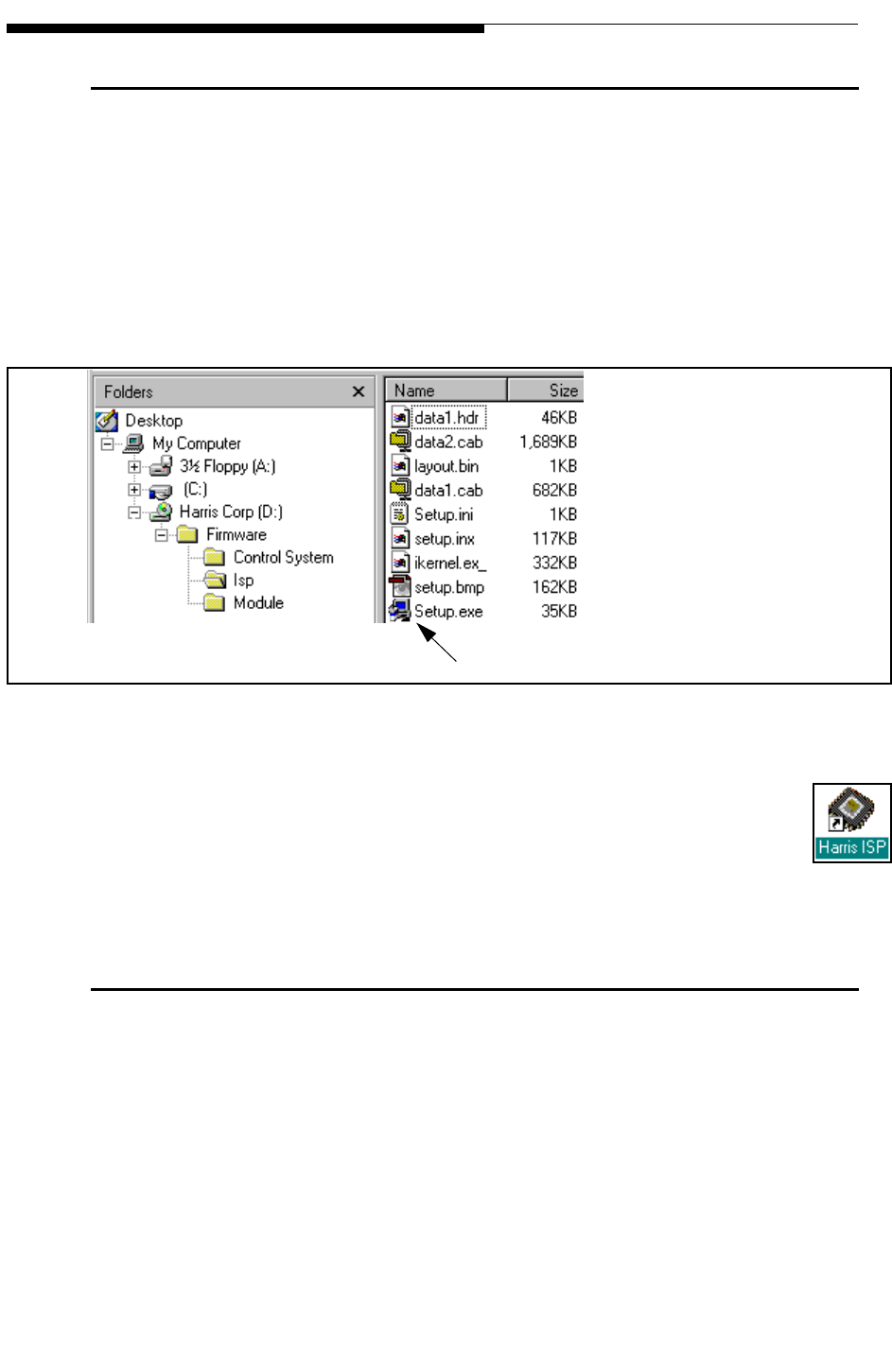
6-2 888-2685-001 12/24/07
WARNING: Disconnect primary power prior to servicing.
Ranger Commissioning Manual
Section 6 ISP (In-System Programming)
6.2 Installing the ISP Program
The In-System Programming (ISP) application, HarrisISP.exe, is a Windows based
software program. The main requirements are a Windows based PC and an open COM
port.
To install the HarrisISP.exe program simply double click the Setup.exe program located
on the CD-ROM in the directory D:\Firmware\Isp\ as shown in Figure 6-1 or use the
RUN command in the START menu.
Figure 6-1 CD-ROM ISP Directory
Simply follow the on screen instructions and do not change the paths where
the program wants to be installed. When finished you should have the Harris
ISP icon on your desktop, like the one to the right.
6.3 ISP Procedures
The ISP procedure is basically the same for all of the control boards (Main Controller,
RF monitor, PS monitor and External I/O) but is slightly different for the PA Module
controller. The main differences are the serial connection point and the baud rate. This
means there are 2 ISP procedures:
• Control System ISP
• PA Module ISP
Double Click to Launch Install program

12/24/07 888-2685-001 6-3
WARNING: Disconnect primary power prior to servicing.
Section 6 ISP (In-System Programming)
Ranger Commissioning Manual
When firmware in the transmitter is updated, all firmware revisions (for the controllers
and the modules) should be checked and brought up to the revision levels on the CD-
ROM if not already the same. The .s19 file names for the controllers and the modules
have the revision number as part of the name.
For example: RANGER_CTRL_APP_0013.s19 is revision 1.3 Main Controller code.
NOTE:
There is a separate ISP procedure used to update the Apex exciter. See the Apex
exciter manual for details on updating Apex exciter software.
6.3.1 Control System ISP Procedure
The example given here is for updating the Main Controller board since the steps are
the same for the other control boards except for the update file. This means the
procedure is to be repeated for updating each of the following control boards:
• Main Controller
• RF Monitor
• PA Monitor
• External I/O
STEP 1 Insert the CD-ROM into the disk drive.
STEP 2 Open the transmitter controller front door. Connect a standard RS-232
cable from the serial port on your computer to DB9 connector J90 on the
left edge of the Main Controller Board.
STEP 3 Run the “Harris ISP.exe” program. The window shown in Figure 6-2
should open.
STEP 4 Set “Port” to the number of the COM port being used on your computer.
STEP 5 Set “Baud” to 19200.
STEP 6 Press Query Micros; wait for system to recognize the 4 controller boards
as shown in Figure 6-3. If it does not find the micros, press Stop Query,
change the COM port and press Query Micros again.
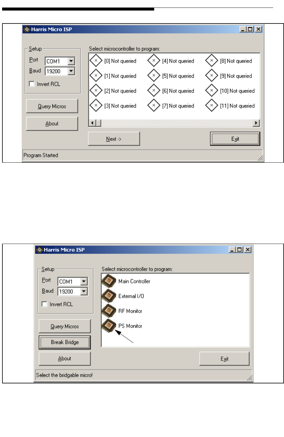
6-4 888-2685-001 12/24/07
WARNING: Disconnect primary power prior to servicing.
Ranger Commissioning Manual
Section 6 ISP (In-System Programming)
Figure 6-2 ISP Opening Screen
STEP 7 If you only see one micro (RF Monitor, PS Monitor or External I/O),
instead of the four, as in Figure 6-3, press the Break Bridge button and
then press Query Micros again. This will clear any previous ISP bridge
connection and you should now see all four micros.
Figure 6-3 Response to “Query Micros”
Double-click to select
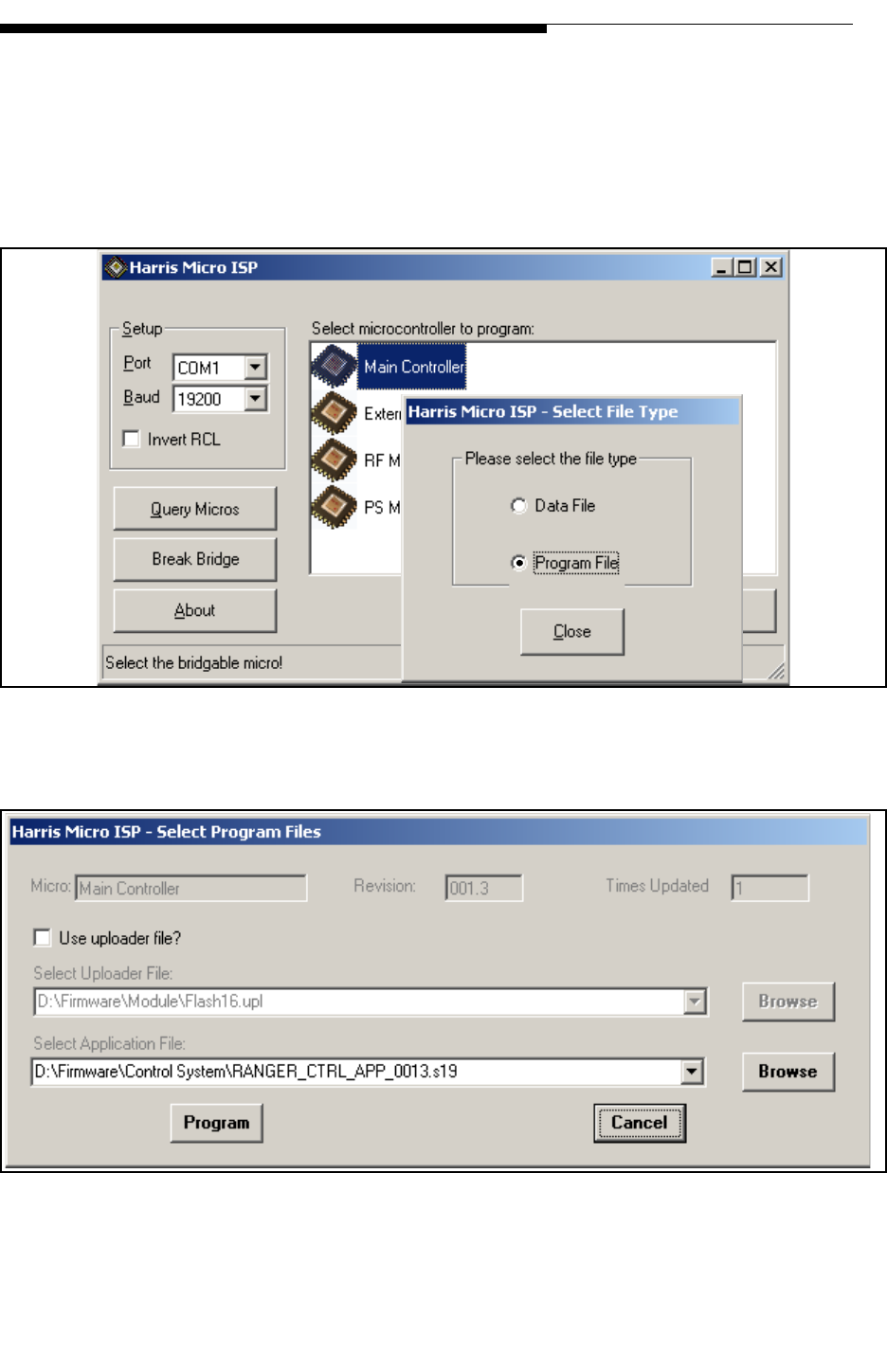
12/24/07 888-2685-001 6-5
WARNING: Disconnect primary power prior to servicing.
Section 6 ISP (In-System Programming)
Ranger Commissioning Manual
STEP 8 Once it has found the micros, select the one you want to update by
double-clicking the icon to the left of the name. This will open the
smaller pop-up window shown in Figure 6-4.
STEP 9 Select the Program File button as shown. This will open the “Select
Program Files” window shown in Figure 6-5.
Figure 6-4 Controller Selected for Update, Program File Selected
Figure 6-5 Browse the CD for the Desired S19 Application File
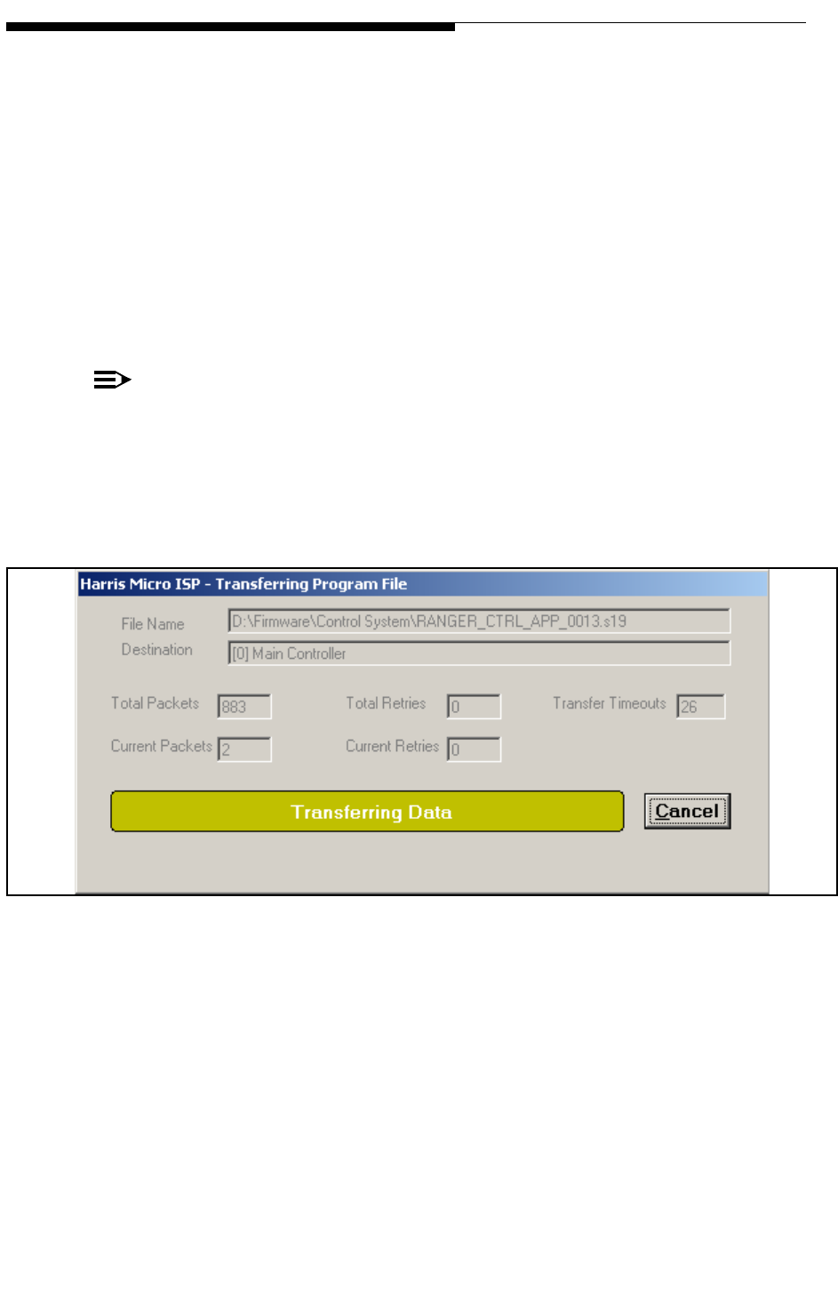
6-6 888-2685-001 12/24/07
WARNING: Disconnect primary power prior to servicing.
Ranger Commissioning Manual
Section 6 ISP (In-System Programming)
STEP 10 Under the “Select Application File” press the browse button and find the
appropriate file on the CD-ROM for the board you are updating. The
files are located on the cd at (insert your drive letter in place of D):
D:\Firmware\Control System\*.s19. The file names are given below.
Note that the numbers to the left of the period are the revision number
and may be different than shown here.
• "RANGER_CTRL_APP_0013.s19" to update the Main Controller
• "RANGER_PSM_APP_0013.s19" to update the PS Monitor
• "RANGER_RFM_APP_0011.s19" to update the RF Monitor
• "RANGER_EXIO_APP_0011.s19" to update the External I/O
NOTE:
Remember to select the correct application file (.s19 file) for the board being
updated.
STEP 11 Press Program. This will open the window in Figure 6-6 which monitors
the transfer process. This will take several minutes.
Figure 6-6 Data Being Transferred (will take several minutes)
STEP 12 When it has transferred all of the new programming packets it will then
take a couple seconds to program the flash chip as shown in Figure 6-7.
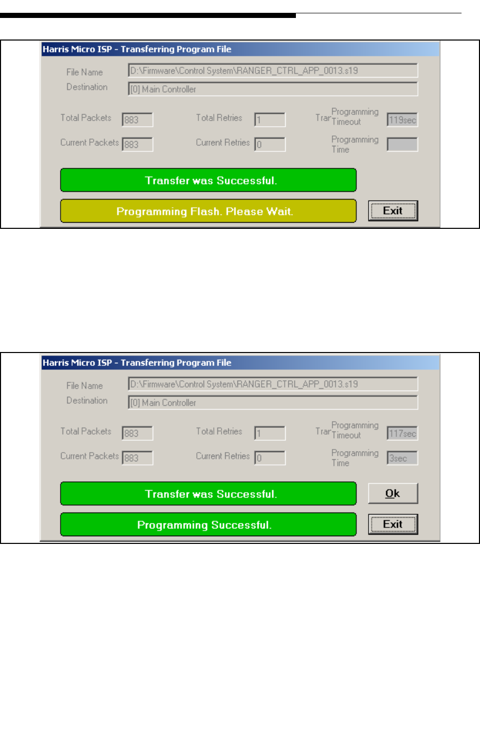
12/24/07 888-2685-001 6-7
WARNING: Disconnect primary power prior to servicing.
Section 6 ISP (In-System Programming)
Ranger Commissioning Manual
Figure 6-7 Programming Flash
STEP 13 The final screen is shown in Figure 6-8 which shows “Programming
Successful”. Press OK to finish the update and get back to the main
screen shown in Figure 6-2. Do not skip STEP 14.
Figure 6-8 Programming Successful
STEP 14 To program another controller board or to simply check the current
firmware revisions, press the “Break Bridge” button and then press
Query micros. This should bring up the display shown in Figure 6-3.
Select the next micro to be updated and repeat the procedure if
necessary.
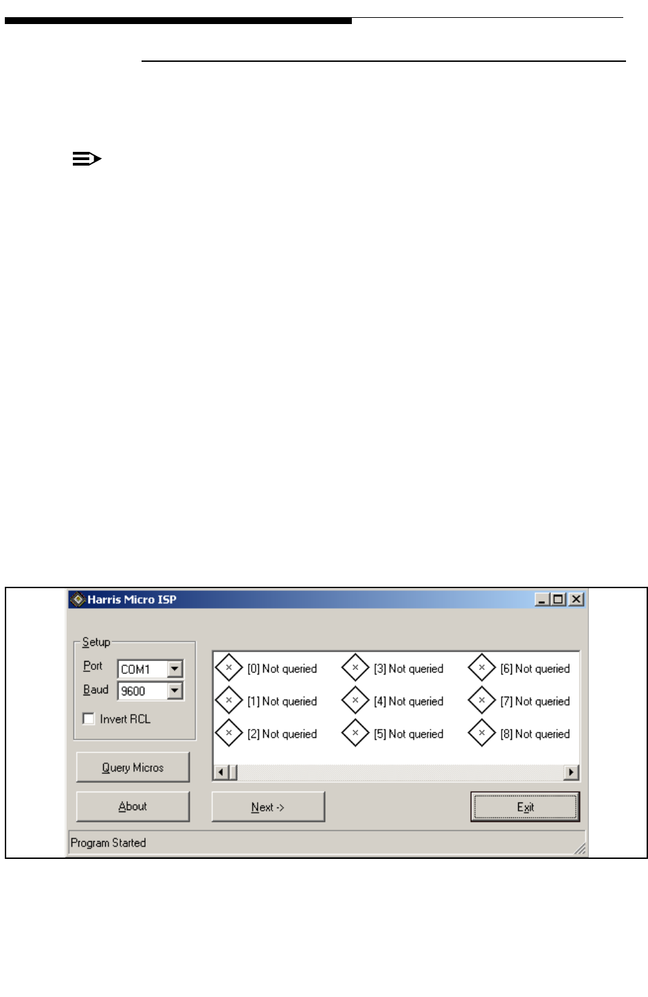
6-8 888-2685-001 12/24/07
WARNING: Disconnect primary power prior to servicing.
Ranger Commissioning Manual
Section 6 ISP (In-System Programming)
6.3.2 PA Module ISP Procedure
This procedure is only for updating the software in the PA Module(s). The
HarrisISP.exe program must have already been installed on your computer.
IMPORTANT:
This procedure is intended for use on the CZ500F and CZ1000F modules only.
STEP 1 Insert the CD-ROM into the disk drive.
STEP 2 Open the transmitter back door. Connect a standard RS-232 cable from
the serial port on your computer to the DB9 serial connector on the
Backplane Interface board. See Figure 2-1 on page 2-2 for physical
board location.
STEP 3 Run the “Harris ISP.exe” program. The window shown in Figure 6-9
should open.
STEP 4 Set “Port” to the number of the COM port being used on your computer.
STEP 5 Set “Baud” to 9600.
STEP 6 Press Query Micros; wait for system to recognize the 1 or 2 PA Module
micros as shown in Figure 6-10. The micros are at address 33 and 34 so
it will take a minute for them to show up. Note the status indicator at the
bottom left corner of the window. If it does not find the micros, press
Stop Query, change the COM port and press Query Micros again.
Figure 6-9 ISP Opening Screen
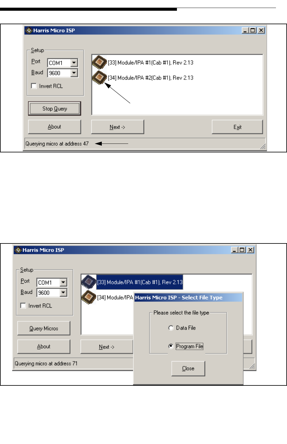
12/24/07 888-2685-001 6-9
WARNING: Disconnect primary power prior to servicing.
Section 6 ISP (In-System Programming)
Ranger Commissioning Manual
Figure 6-10 Response to “Query Micros”
STEP 7 Once it has found the micros, select the one you want to update by
double-clicking the icon to the left of the name. This will open the
smaller pop-up window shown in Figure 6-11. Select the Program File
button as shown. This will open the “Select Program Files” window
shown in Figure 6-12.
Figure 6-11 Controller Selected for Update, Program File Selected
Double Click to Select
Status Indicator
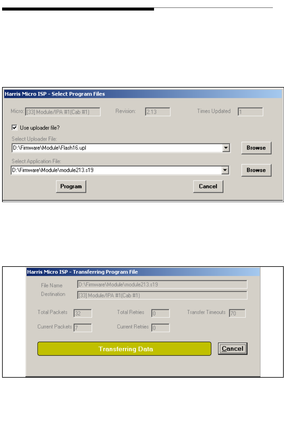
6-10 888-2685-001 12/24/07
WARNING: Disconnect primary power prior to servicing.
Ranger Commissioning Manual
Section 6 ISP (In-System Programming)
STEP 8 Make sure the “Use uploader file?” box is checked as shown in Figure
6-12 and browse to find the uploader file “Flash16.upl” on the CD-
ROM. It is located in the directory D:\Firmware\module\
STEP 9 Under the “Select Application File” press the browse button to find the
“module213.s19” application file in the same directory. The 213 means
revision 2.3 and therefore may be different on your disk.
Figure 6-12 Select Uploader and Application File
STEP 10 Press Program. This will open the window in Figure 6-13 which
monitors the transfer process. This will take several minutes.
Figure 6-13 Data Being Transferred (will take several minutes)
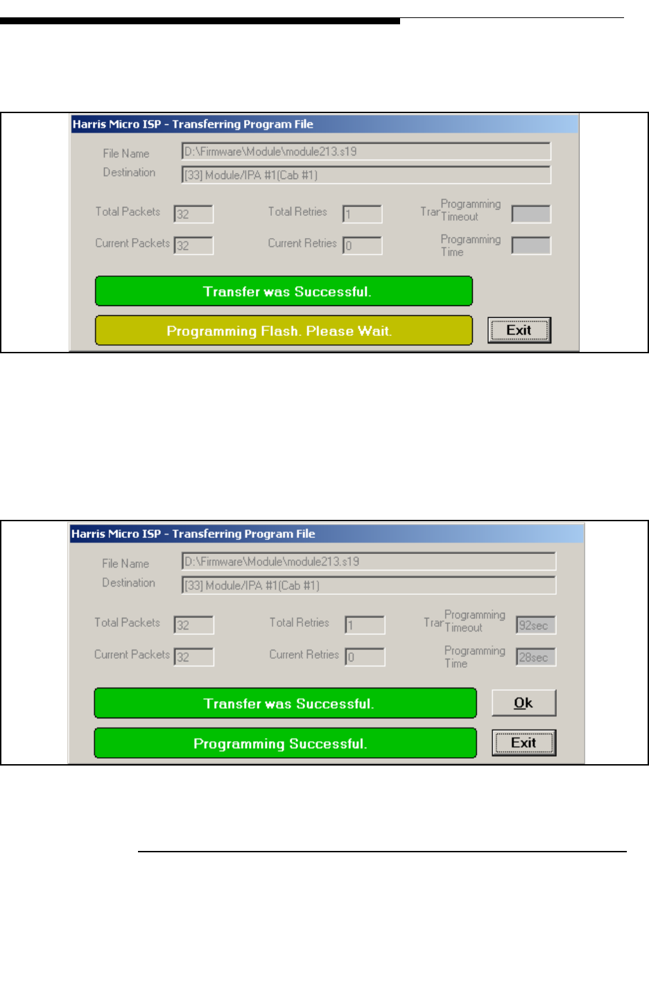
12/24/07 888-2685-001 6-11
WARNING: Disconnect primary power prior to servicing.
Section 6 ISP (In-System Programming)
Ranger Commissioning Manual
STEP 11 When it has transferred all of the new programming packets it will then
take a couple seconds to program the flash chip as shown in Figure 6-14.
Figure 6-14 Programming Flash
STEP 12 The final screen is shown in Figure 6-15 which shows “Programming
Successful”. Press OK to finish the update and then repeat the procedure
to update the second PA Module, at address 34, for the CZ1000F.
Figure 6-15 Programming Successful
6.3.3 ISP Errors
If an error is encountered during the ISP process, close the program, check or change
the serial cable and try the procedure again. If the problem persists, contact Harris
technical support.

6-12 888-2685-001 12/24/07
WARNING: Disconnect primary power prior to servicing.
Ranger Commissioning Manual
Section 6 ISP (In-System Programming)