GemTek Technology ADV981119G ADSL2+ Residential Gateway User Manual Cisco 4020210A
Gemtek Technology Co., Ltd. ADSL2+ Residential Gateway Cisco 4020210A
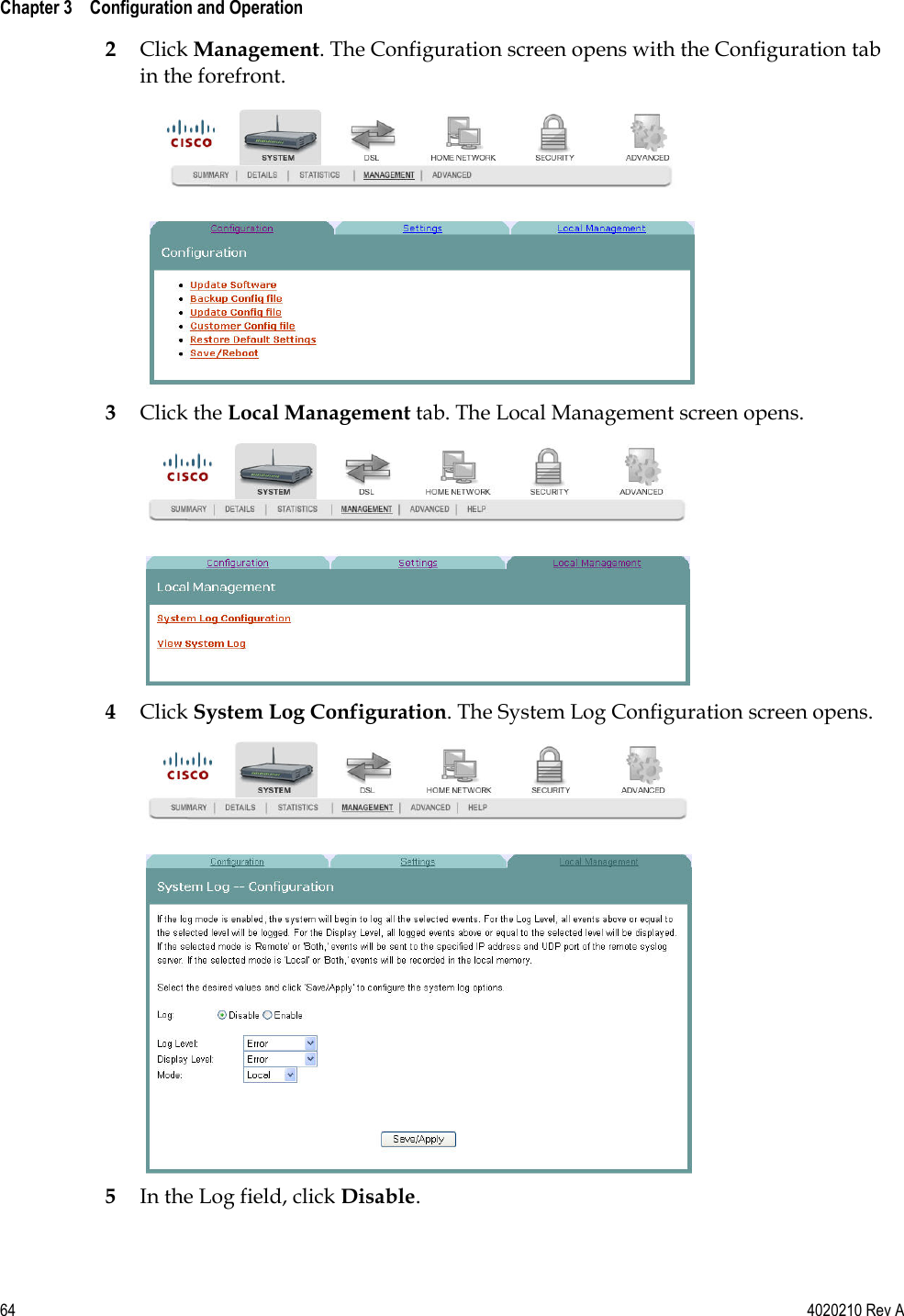
UserManual.wiki
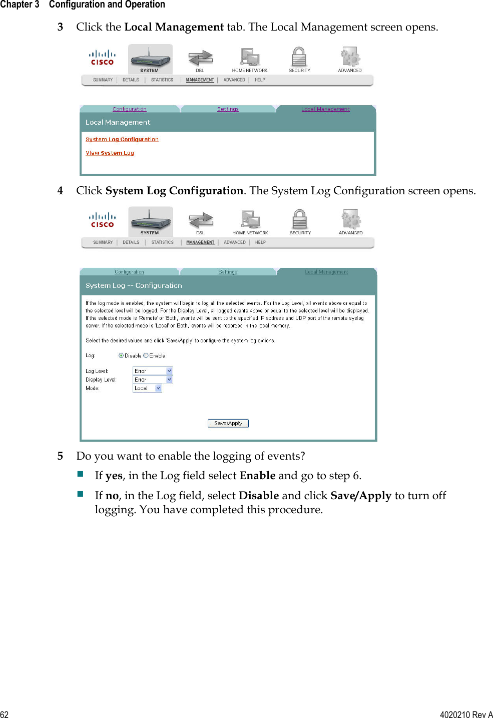
>
GemTek Technology
>
ADV981119G User Manual
>
Manual Part 2
Contents
1.
Manual Part 1
2.
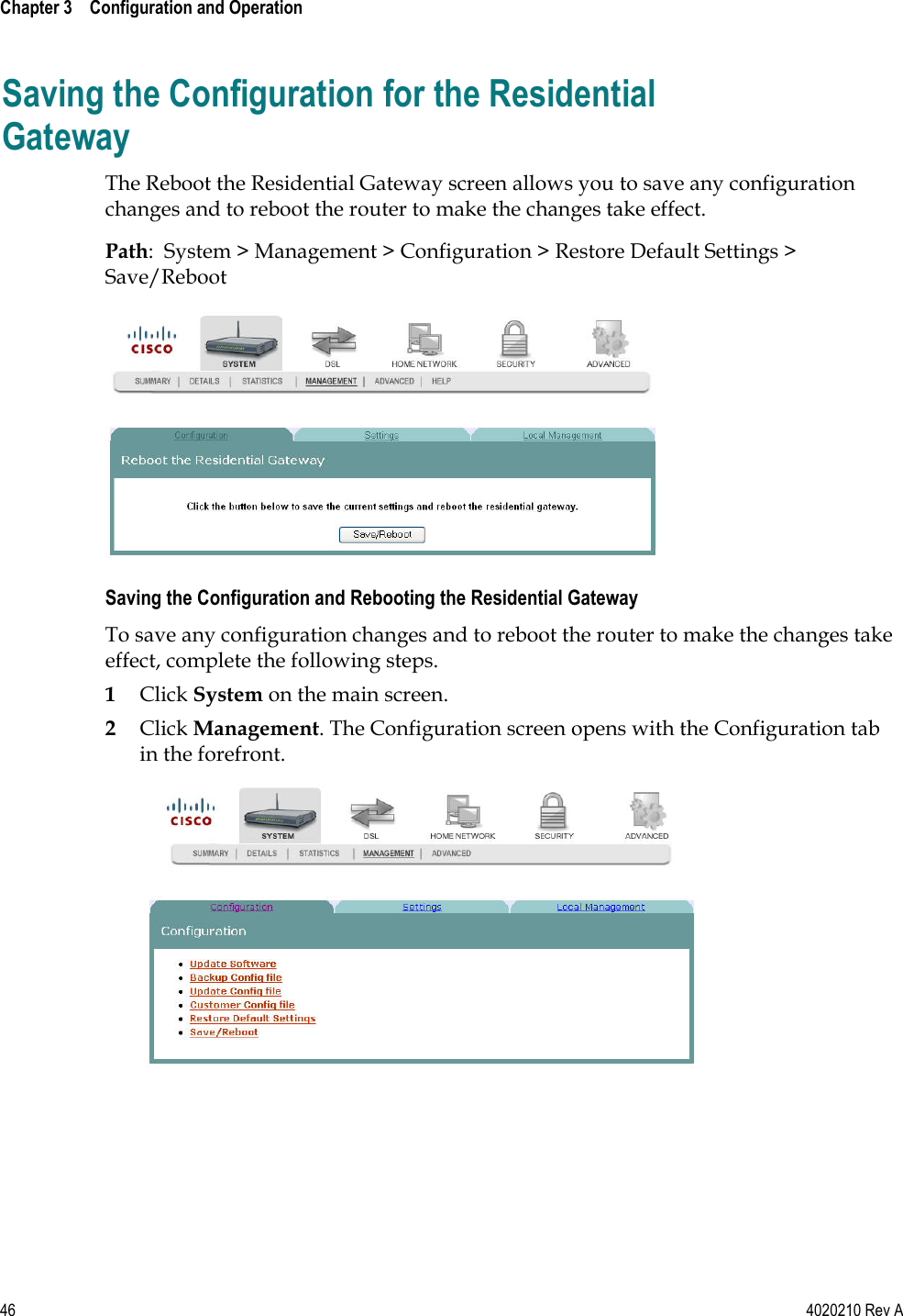
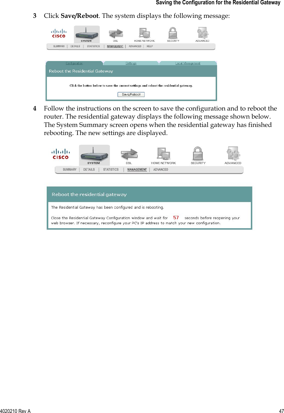
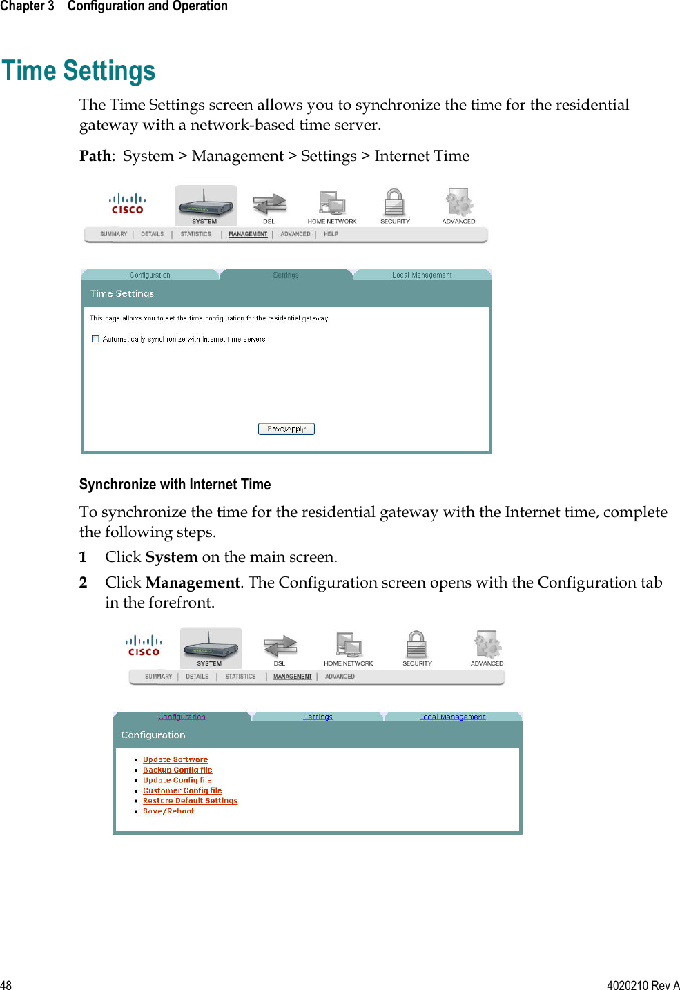
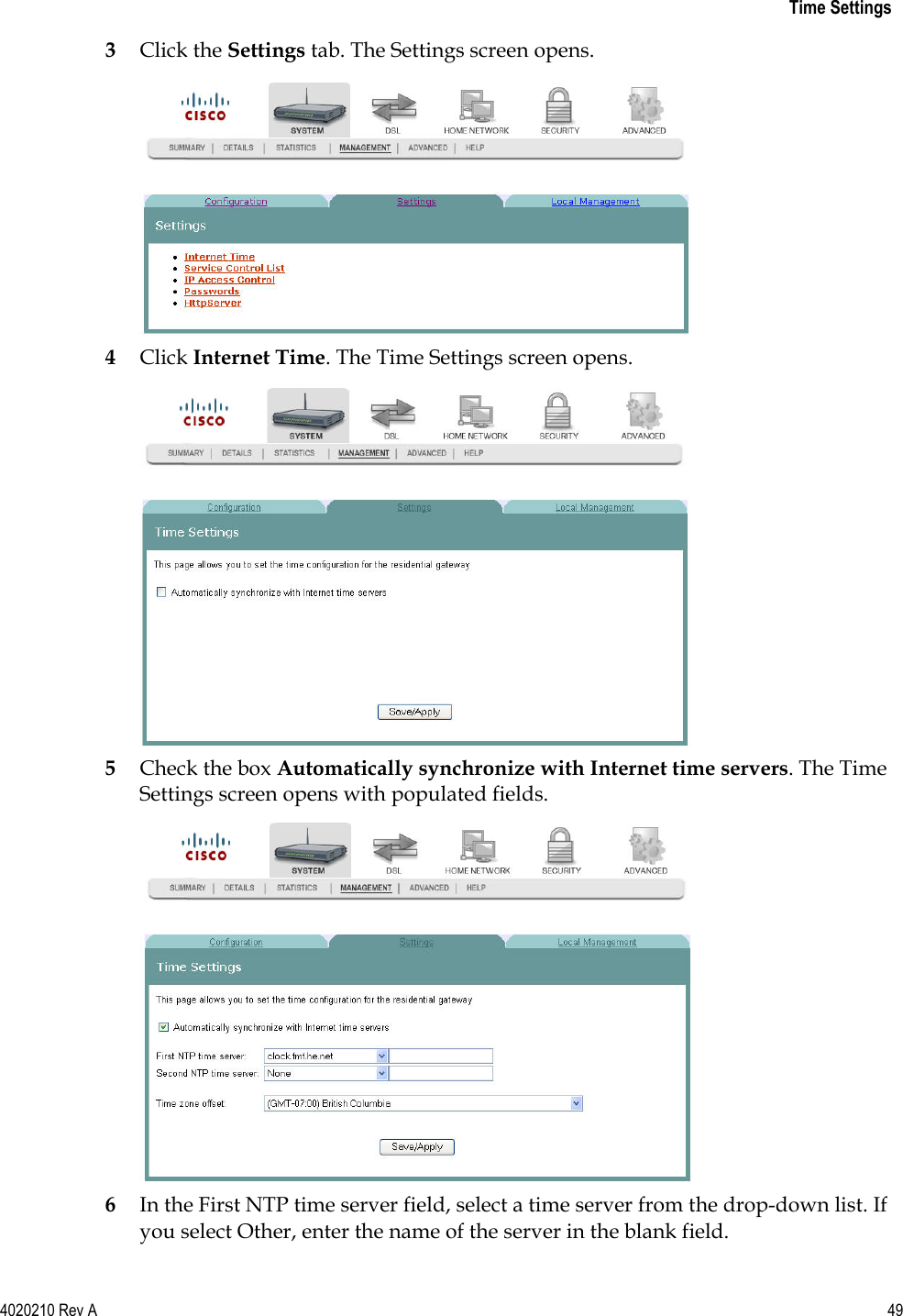
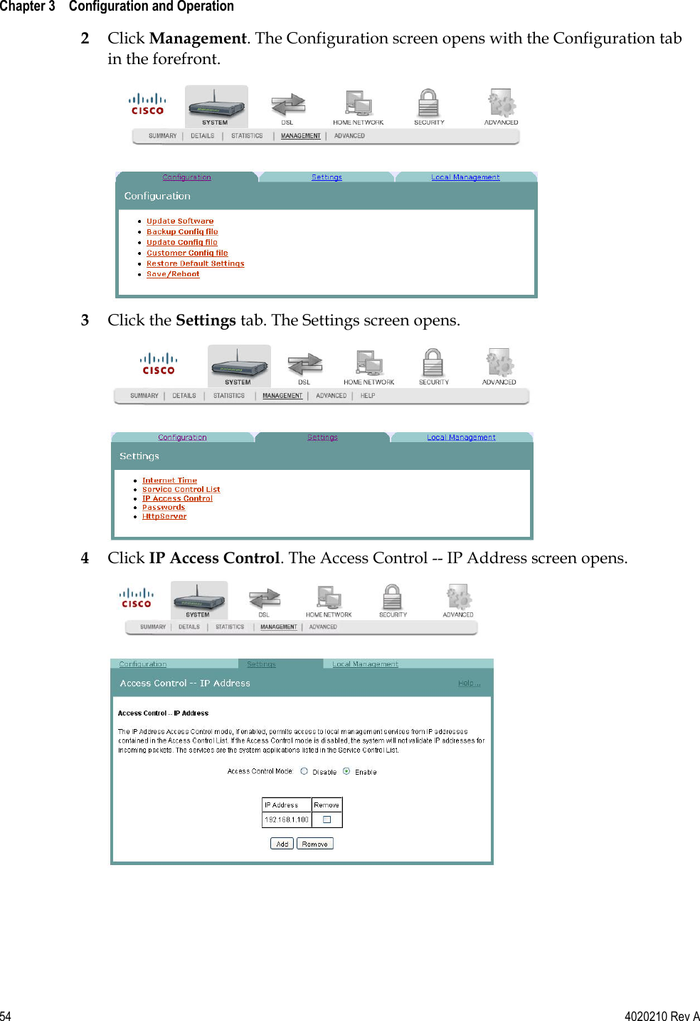
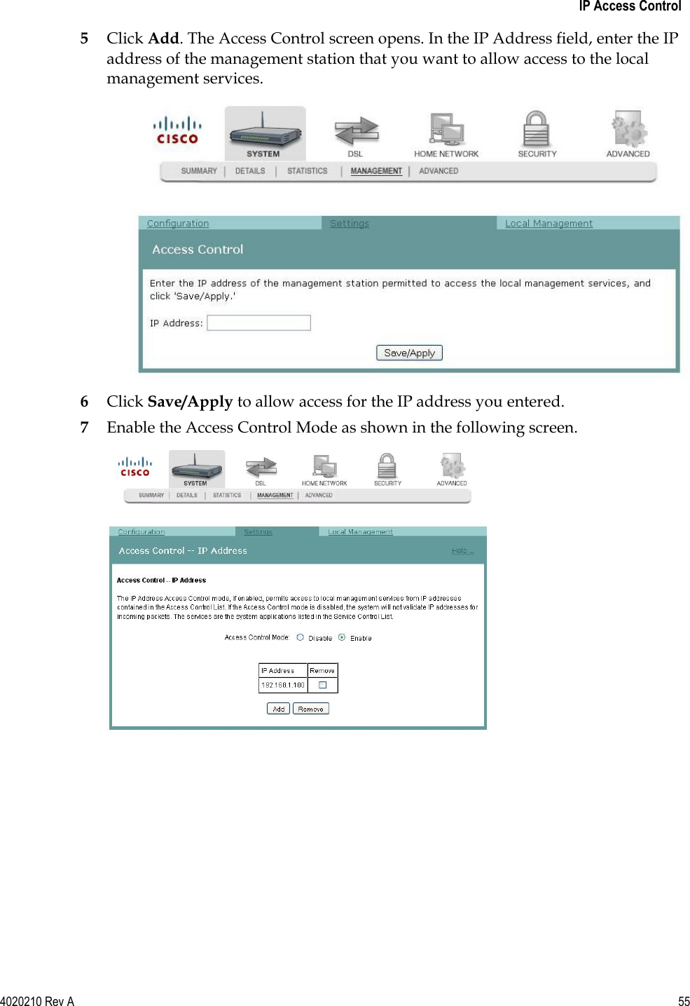
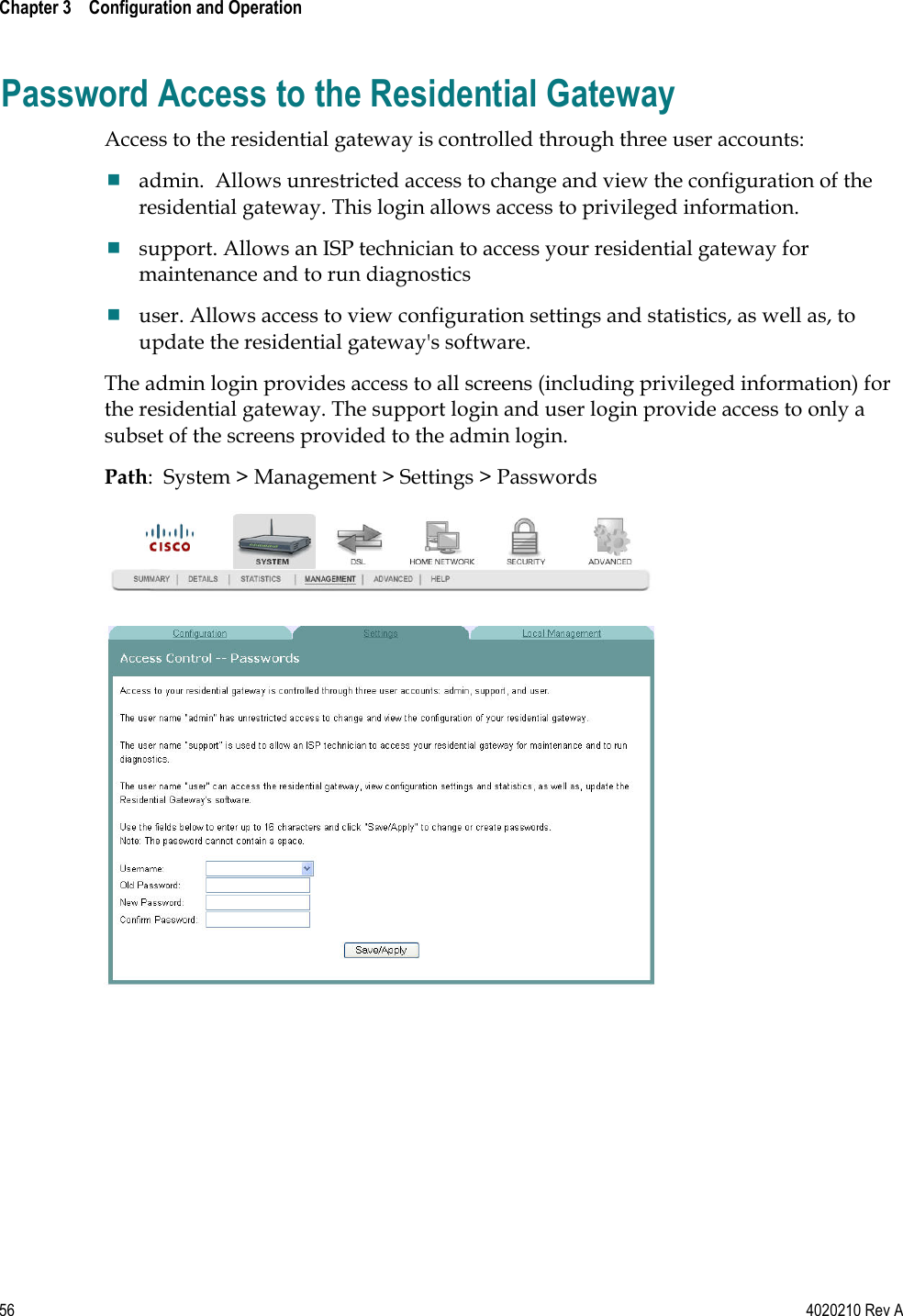
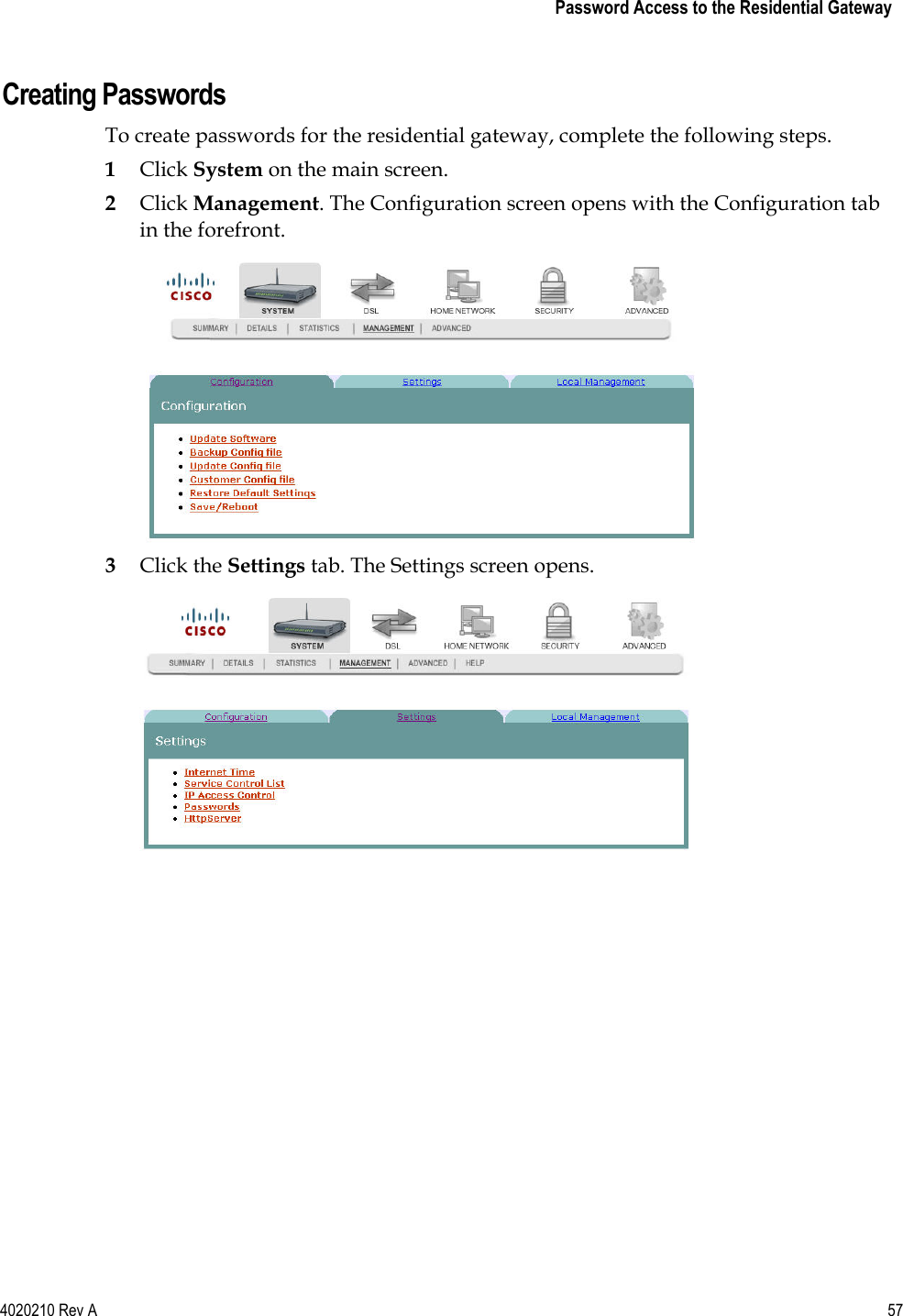
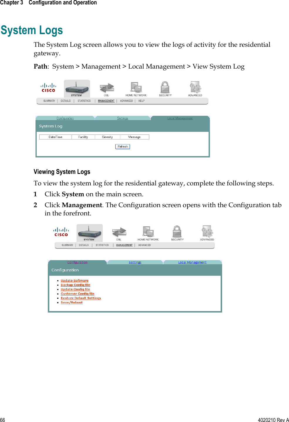
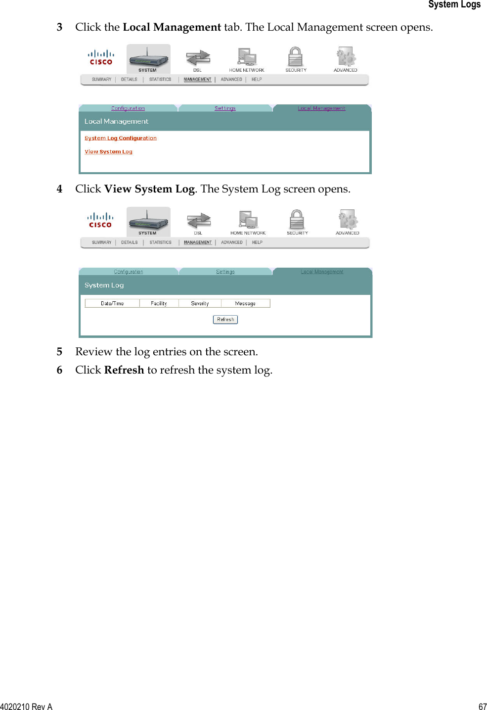
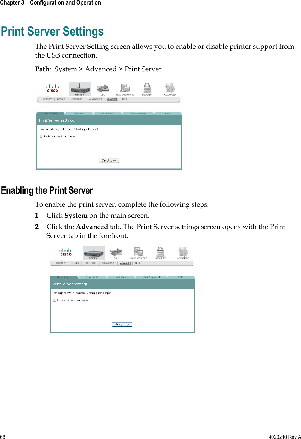
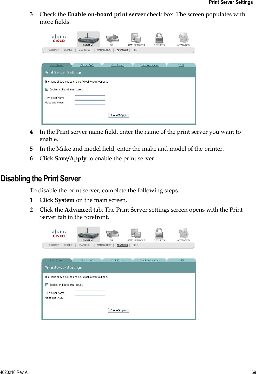
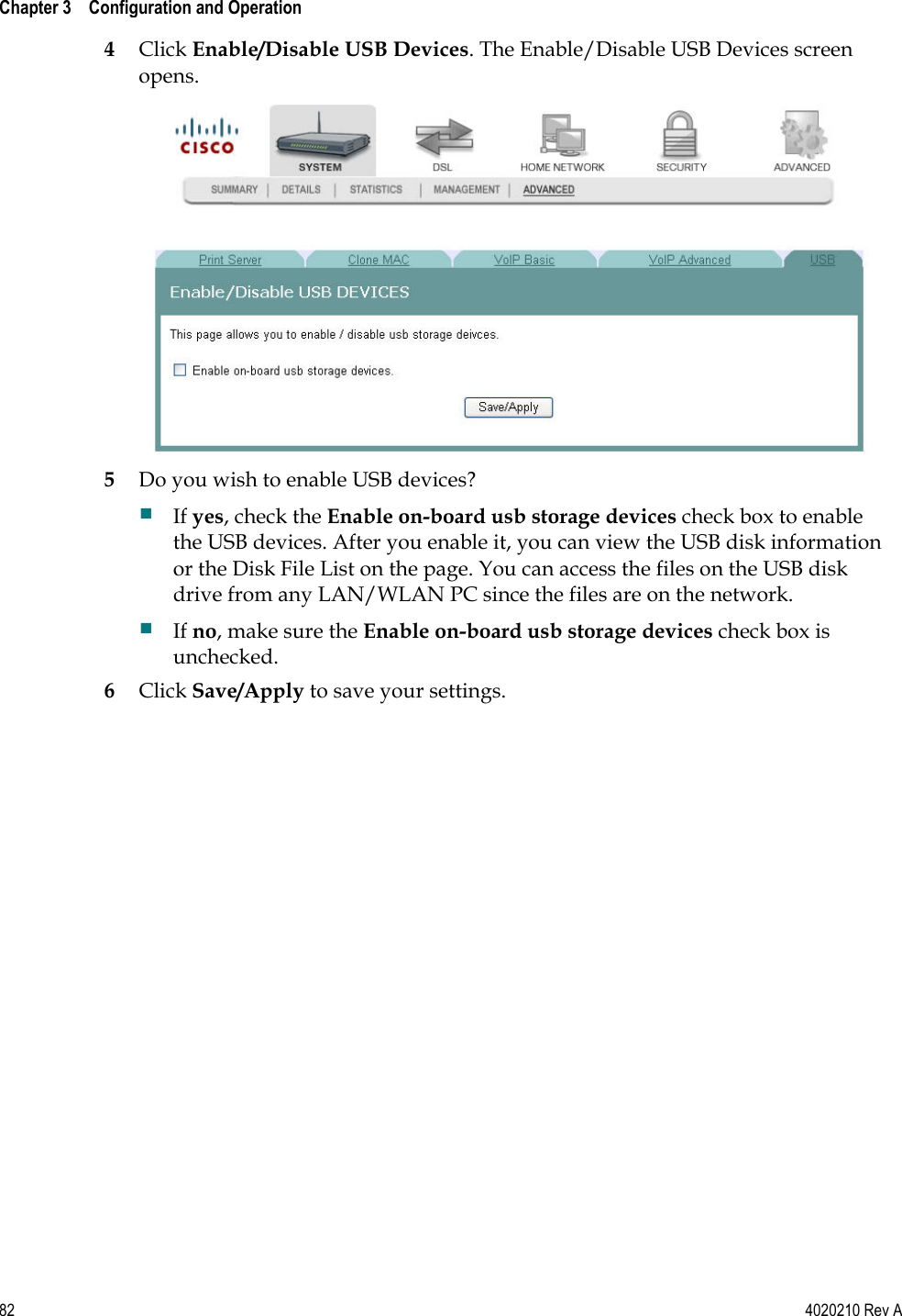
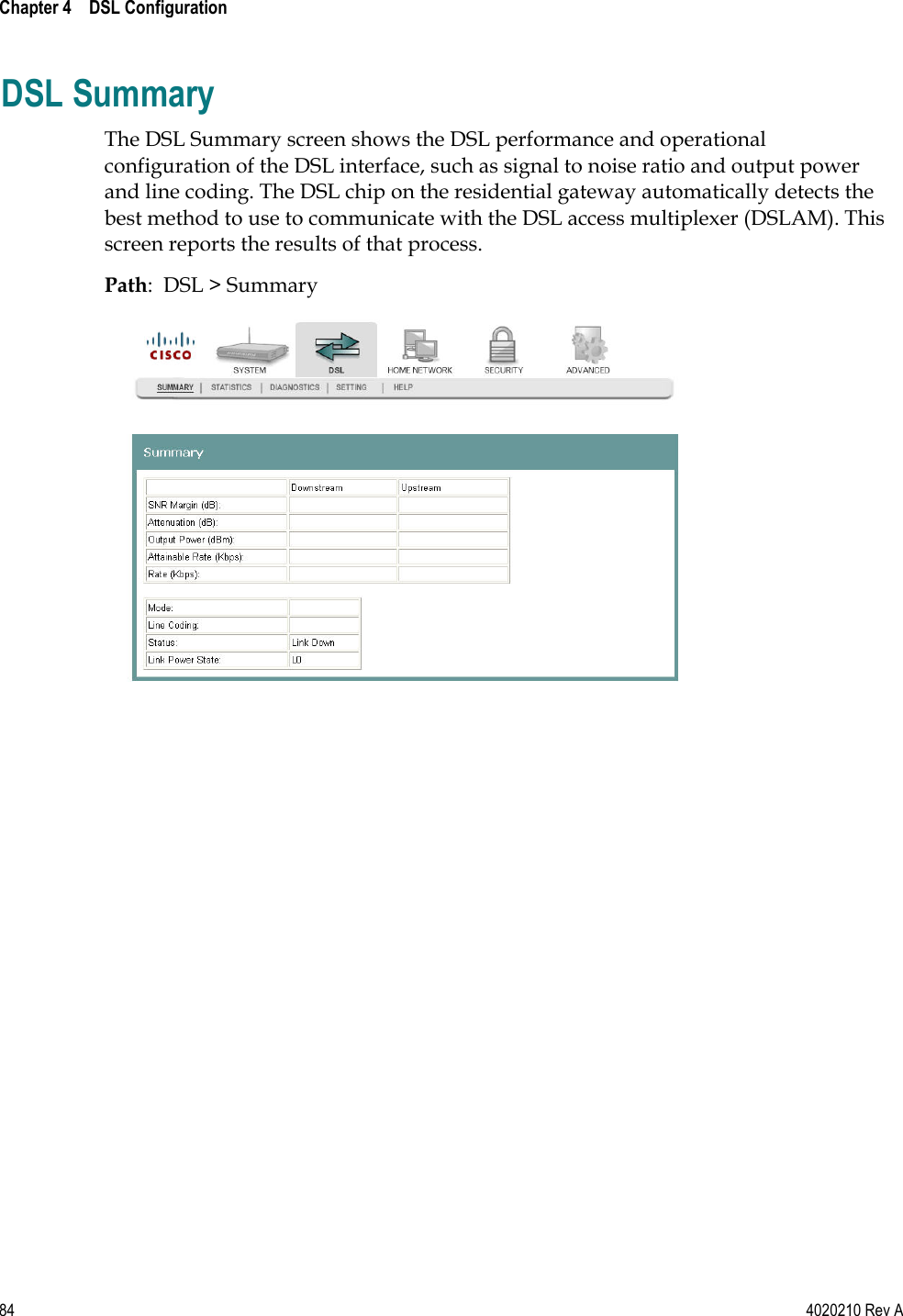
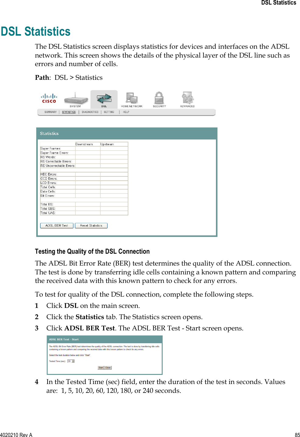
Manual Part 2
3.
Manual Part 3
4.
Manual Part 4
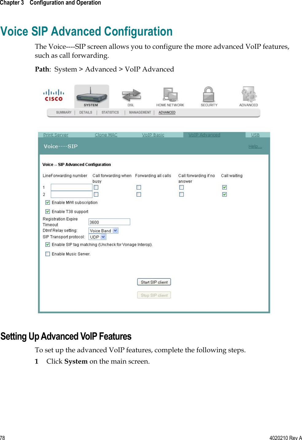
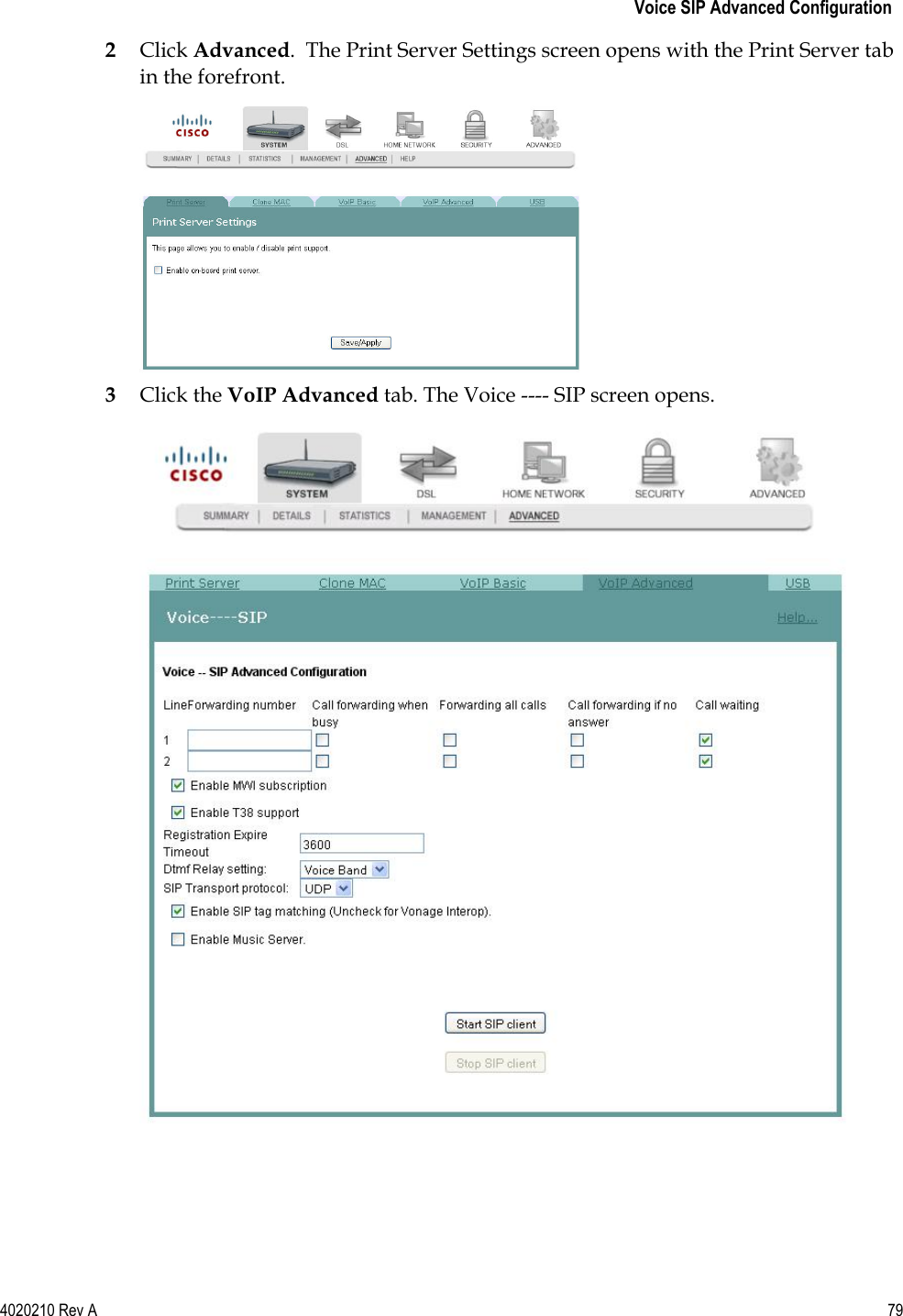
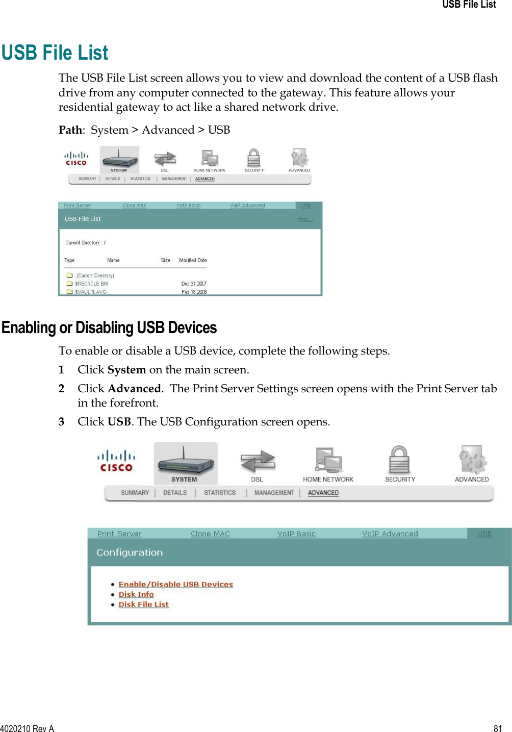
Manual Part 2
Navigation menu
Upload a User Manual
Namespaces
Wiki Guide
HTML
PDF
Info
Views
User Manual
Discussion / Help
Navigation