GemTek Technology ADV981119G ADSL2+ Residential Gateway User Manual Cisco 4020210A
Gemtek Technology Co., Ltd. ADSL2+ Residential Gateway Cisco 4020210A
Contents
- 1. Manual Part 1
- 2. Manual Part 2
- 3. Manual Part 3
- 4. Manual Part 4
Manual Part 2
Cha
p
te
r
3 Confi
g
uration and O
p
eration
18 4020210
Rev
A
In This Chapter
Logging In to the Residential Gateway ............................................. 19
Setting Up Your System with the Setup Wizard.............................. 21
Setting System Date and Time............................................................ 25
Setting Password................................................................................... 26
DHCP Leases......................................................................................... 27
WAN Information................................................................................. 28
Route Information................................................................................. 29
ARP Information................................................................................... 30
CPU Information................................................................................... 31
Memory Information............................................................................ 32
LAN Statistics........................................................................................ 33
WAN Statistics ...................................................................................... 34
ATM Statistics ....................................................................................... 35
Tools Update Software......................................................................... 36
Updating Software................................................................................ 37
Settings Backup..................................................................................... 38
Update Settings..................................................................................... 40
Customer Configuration File .............................................................. 42
Restore Default Settings....................................................................... 44
Saving the Configuration for the Residential Gateway................... 46
Time Settings ......................................................................................... 48
Service Control...................................................................................... 51
IP Access Control.................................................................................. 53
Password Access to the Residential Gateway .................................. 56
HTTP Server Port.................................................................................. 59
System Log Configuration................................................................... 61
System Logs........................................................................................... 66
Print Server Settings ............................................................................. 68
Clone MAC Addresses......................................................................... 71
Voice SIP Basic Configuration ............................................................ 74
Voice SIP Advanced Configuration ................................................... 78
USB File List........................................................................................... 81
4020210 Rev
A
19
Logging In to the Residential Gateway
The default configuration of the residential gateway uses IP address 192.168.1.254. If
you have connected the residential gateway correctly and you have properly
configured your computer, use the following steps to log in to the residential
gateway as an administrator.
Note: A non-administrative user may need a different user name and password for
logging in to the residential gateway. These users can access non-privileged
information.
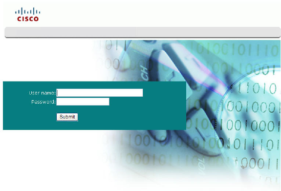
1 On your PC, open the web browser that you prefer to use.
2 In the address field, enter the following IP address: 192.168.1.254. The system
prompts you to enter your user name and password.
3 Enter admin for the user name and 1PTV-ADM1N (where 1 is the numeral one
in both 1PTV and ADM1N) for the password. The residential gateway opens
with the System Summary page in the forefront. You can use this web interface
to check the status of the residential gateway and to configure parameters.
Note: The screens shown in this guide represent the default values for the
device.
Cha
p
te
r
3 Confi
g
uration and O
p
eration
20 4020210
Rev
A
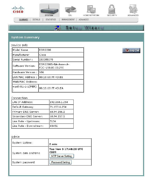
System Summary
The System Summary screen provides a summary of the software used by the
residential gateway and indicates the current status of the DSL connection. You can
use this screen to find hardware and software information as well as physical and IP
layer information.
This screen also provides a link to the Setup Wizard. The Setup Wizard is a step-by-
step sequence to set up your residential gateway for the first time to ensure proper
operation.
The Log Out button on this screen allows you to quickly log out and log back in
without opening a browser.
Path: System > Summary
Setting Up Your System with the Setup Wizard
4020210 Rev
A
21
Setting Up Your System with the Setup Wizard
The Setup Wizard is a step-by-step sequence to set up your residential gateway for
the first time to ensure proper operation. The wizard combines the various tasks into
one convenient tool to reduce configuration time. The wizard requires that you make
a few selections within this process. Your selections will depend on your service
provider.
To set up your system with the Setup Wizard, complete the following steps.
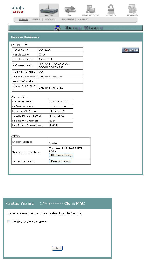
1 Click System on the main screen. The System Summary window opens.
2 Click Setup Wizard at the top of the screen. The (Setup Wizard 1/4) ------ Clone
MAC screen opens.
Cha
p
te
r
3 Confi
g
uration and O
p
eration
22 4020210
Rev
A
3 Do you want to enable the clone MAC function? MAC cloning enables you to
change the MAC address of the residential gateway to match the MAC address
of your PC or any service provider supplied MAC address. If you do not enable
MAC cloning, the default MAC address of the residential gateway is used.
If yes, select the Enable clone MAC address check box. A field appears for
you to enter the MAC address you want to clone. Go to step 4.
If no, clear the Enable clone MAC address check box. Go to step 5.
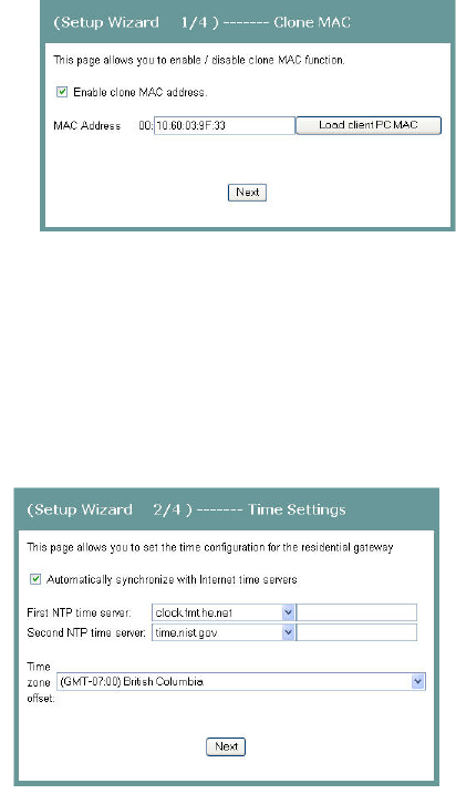
4 In the MAC address field, type in a MAC address or click Load client PCMAC to
load your PC's MAC address.
5 Click Next. The (Setup Wizard 2/4 ------- Time Settings) screen opens. This
screen lets you synchronize the time on the residential gateway with an Internet
time server. If you do not synchronize the time with an Internet time server, the
residential gateway will use its default time.
6 Do you want to automatically synchronize the time on the residential gateway
with an Internet Time server?
If yes, check the Automatically synchronize with Internet time servers check
box. Go to step 7.
If no, clear the Automatically synchronize with Internet time servers check
box. The residential gateway will get its time from its own internal clock. Go
to step 9.
7 In the First NTP time server field, select the Network Time Protocol (NTP) time
server from the drop-down list that you want the residential gateway to check
first to get its time.
8 In the Second NTP time server field, select the time server from the drop-down
list that you want to use as a backup server for the residential gateway to get its
time.
Setting Up Your System with the Setup Wizard
4020210 Rev
A
23
9 In the Time zone offset field, select your time zone from the drop-down list.
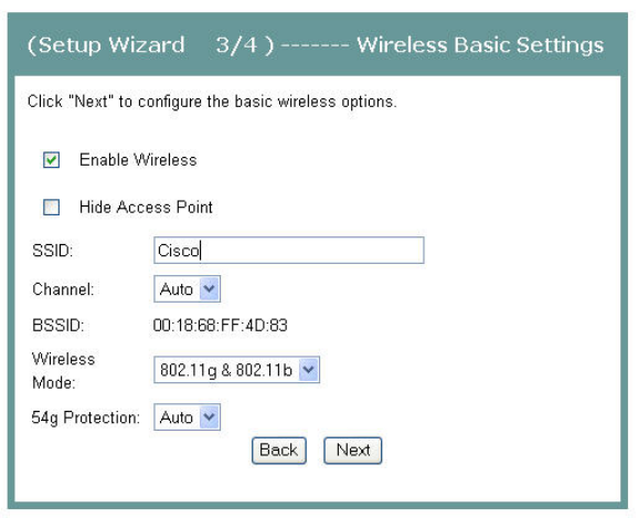
10 Click Next. The (Setup Wizard 3/4) ------- Wireless Basic Settings screen opens.
The residential gateway offers wireless capability by default. This screen allows
you to configure the wireless settings to work with the devices in your
environment.
11 Do you want to enable wireless?
If yes, check the Enable Wireless check box.
If no, clear the Enable Wireless check box. The wireless capability of the
residential gateway is disabled, and all devices communicating with the
residential gateway will have to be hard wired.
12 Do you want to prevent other wireless devices from communicating over the
wireless network with the residential gateway?
If yes, select the Hide Access Point check box.
If no, clear the Hide Access Point check box. No devices will be locked out
from communicating with the residential gateway over the wireless network.
13 In the SSID field, enter the service set identifier (SSID).
14 In the Channel field, select the channel from the drop-down list to select the
frequency that you will use for wireless communication. Values are auto and
channels 1 through 11.
Cha
p
te
r
3 Confi
g
uration and O
p
eration
24 4020210
Rev
A
15 In the Wireless Mode field, select one of the following modes:
802.11g & 802.11b
802.11g only
802.11b only
16 In the 54g Protection field, select Auto to enable 54g protection or Off to disable
the function. The Auto option will use RTS/CTS to improve 802.11g performance
in mixed 802.11g/802.11b networks. Turning the protection off maximizes
802.11g throughput under most conditions.
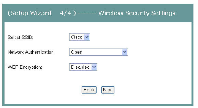
17 Click Next. The (Setup Wizard 4/4) ----- Wireless Security Settings screen opens.
18 In the Select SSID field, select the SSID from the drop-down list that you want to
use.
19 In the Network Authentication field, choose one of these two options for the
authentication method:
Open. All devices may access the wireless network when WEP Encryption is
disabled. When no authentication is required and if encryption is disabled,
then the data that is passing between the access point and the client is also
not encrypted. When WEP is enabled, the data is encrypted, but the client is
not authenticated.
WPA/WPA2. See Securing Your Wireless Network with Encryption Keys (on
page 120).
20 Do you want to enable WEP Encryption?
If yes, in the WEP Encryption field, select Enabled from the drop-down list.
If no, in the WEP Encryption field, select Disabled from the drop-down list.
21 Click Save/Reboot to save the changes you made. You must reboot the gateway
for the changes to take effect.
Setting System Date and Time
4020210 Rev
A
25
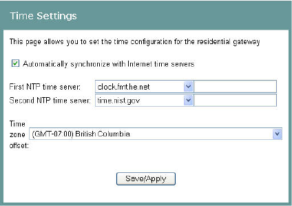
Setting System Date and Time
When you first set up your system with the wizard, you set your system's date and
time. At a later time, you may need to reset the date and time, and you can use the
following procedure.
To set the system date and time, complete the following steps.
1 Click System on the main screen. The System Summary window opens.
2 Under the Admin section on the screen, click NTP Server Setting. The Time
Settings screen opens.
3 Make sure the Automatically synchronize with Internet time servers check box is
checked.
4 In the First NTP time server field, select clock.fmt.he.net from the drop-down
list.
5 In the Second NTP time server field, select time.nist.gov from the drop-down
list.
6 In the Time zone offset field, select the time zone that you want to use from the
drop-down list.
7 Click Save/Apply to save your settings.
Cha
p
te
r
3 Confi
g
uration and O
p
eration
26 4020210
Rev
A
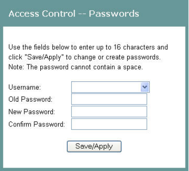
Setting Password
To set the password for the residential gateway, complete the following steps.
1 Click System on the main screen. The System Summary window opens.
2 Under the Admin section on the screen, click Password Setting. The Access
Control -- Password screen opens.
3 In the Username field, select one of the following options for the user name:
admin. Allows unrestricted access to change and view the configuration of
the residential gateway. This login allows access to privileged information.
The default password for this user name is 1PTV-ADM1N (where 1 is the
numeral one in both 1PTV and ADM1N).
support. Allows an ISP technician to access your residential gateway for
maintenance and to run diagnostics. The default password for this user name
is 1PTV-SUPP0RT (where 1 is the numeral in 1PTV and 0 is the numeral 0 in
SUPP0RT).
user. Allows access to view configuration settings and statistics, as well as, to
update the residential gateway's software. The default password is user.
4 In the Old Password field, enter the old password you have been using.
5 In the New Password field, enter the new password.
6 In the Confirm Password field, enter the new password again to confirm it.
7 Click Save/Apply to save your user name and password.
DHCP Leases
4020210 Rev
A
27
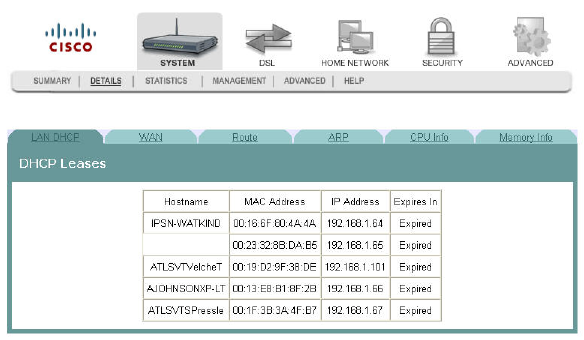
DHCP Leases
The DHCP Leases screen displays the Dynamic Host Configuration Protocol (DHCP)
table. This screen shows a mapping of hosts (shown by their MAC addresses) and
their assigned IP addresses. The DHCP server for the residential gateway assigns
these IP addresses to the devices. The screen also shows when the lease for the IP
address expires.
Path: System > Details > LAN DHCP
Cha
p
te
r
3 Confi
g
uration and O
p
eration
28 4020210
Rev
A
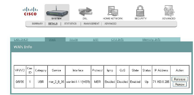
WAN Information
The WAN Info screen provides information about the ADSL2+ wide area network
(WAN) parameters and status. You can use this screen to check the ADSL2+
connection.
Path: System > Details > WAN
In MER protocol (as shown here), press Release or Renew to release your current
WAN IP address and obtain a new DHCP lease. In PPPoE or PPPoA protocol (not
shown here), press Connect to activate a new WAN connection or press Disconnect
to disable the connection.
Route Information
4020210 Rev
A
29
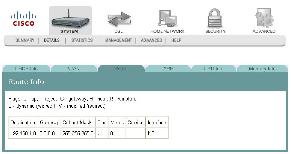
Route Information
The Route Info screen shows the routing table for the residential gateway. This
screen provides the gateway address for specific destination IP addresses.
Path: System > Details > Route
Cha
p
te
r
3 Confi
g
uration and O
p
eration
30 4020210
Rev
A
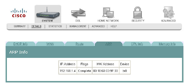
ARP Information
The ARP Info screen displays the Address Resolution Protocol (ARP) table. This
table shows the IP address to MAC address mapping.
Path: System > Details > ARP
CPU Information
4020210 Rev
A
31
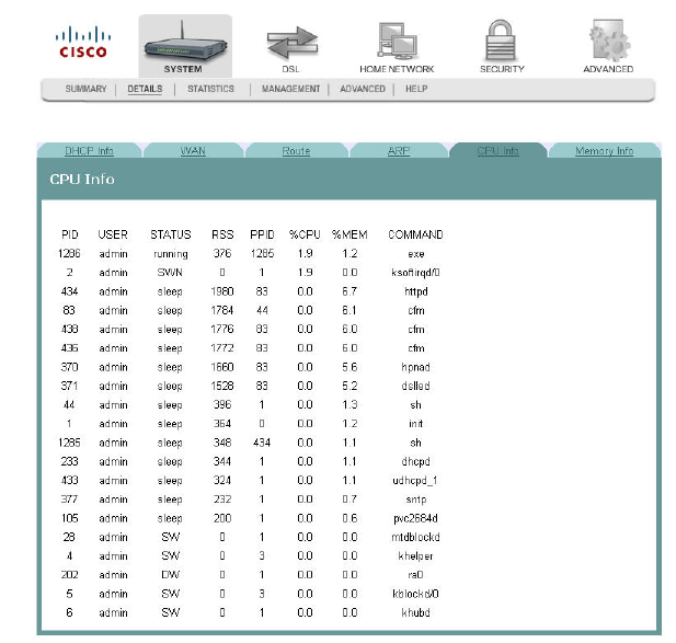
CPU Information
The CPU Info screen shows detailed information about the CPU utilization and the
active processes running on the residential gateway.
Path: System > Details > CPU Info
Cha
p
te
r
3 Confi
g
uration and O
p
eration
32 4020210
Rev
A
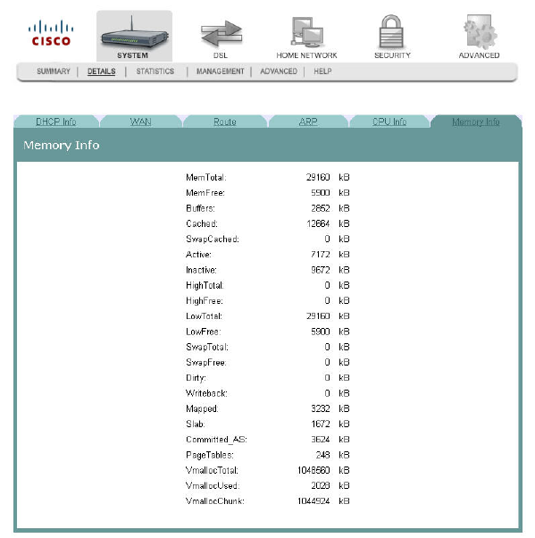
Memory Information
The Memory Info screen shows the detailed memory availability of the residential
gateway.
Path: System > Details > Memory Info
LAN Statistics
4020210 Rev
A
33
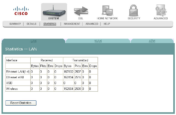
LAN Statistics
The Statistics -- LAN screen displays statistics for the local area network (LAN). This
screen shows the number of transmitted and received packets on the LAN interface
for Ethernet, USB, and wireless devices.
Path: System > Statistics > LAN
Reset Statistics
To reset the statistics, click Reset Statistics on the screen. This action clears the
counters and sets them to zero for the packets received and transmitted on the LAN
interface.
Cha
p
te
r
3 Confi
g
uration and O
p
eration
34 4020210
Rev
A
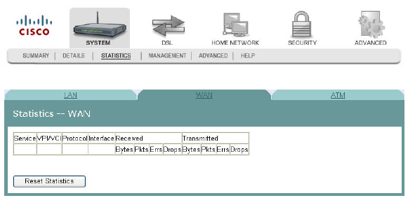
WAN Statistics
The Statistics -- WAN screen displays statistics for the devices and interfaces on the
wide area network (WAN). This screen shows the number of transmitted and
received packets for the DSL WAN interface.
Path: System > Statistics > WAN
Reset Statistics
To reset the statistics, click Reset Statistics on the screen. This action clears the
counters and sets them to zero for the packets received and transmitted on the WAN
interface.
ATM Statistics
4020210 Rev
A
35
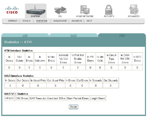
ATM Statistics
The Statistics -- ATM screen displays statistics on the ATM interface. This screen
shows the ATM Layer-2 statistics such as the number of ATM cells transmitted and
received over the ATM interface.
Path: System > Statistics > ATM
Reset Statistics
To reset the statistics, click Reset on the screen. This action clears the counters and
sets them to zero for the packets received and transmitted on the ATM interface.
Cha
p
te
r
3 Confi
g
uration and O
p
eration
36 4020210
Rev
A
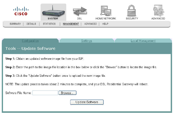
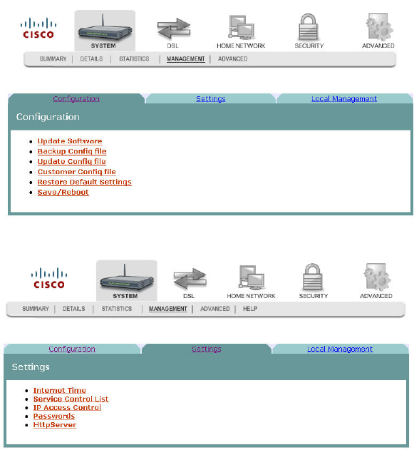
Tools Update Software
The Tools -- Update Software screen allows you to update the software for the
residential gateway with a new version.
Path: System > Management > Configuration > Update Software
Updating Software
4020210 Rev
A
37
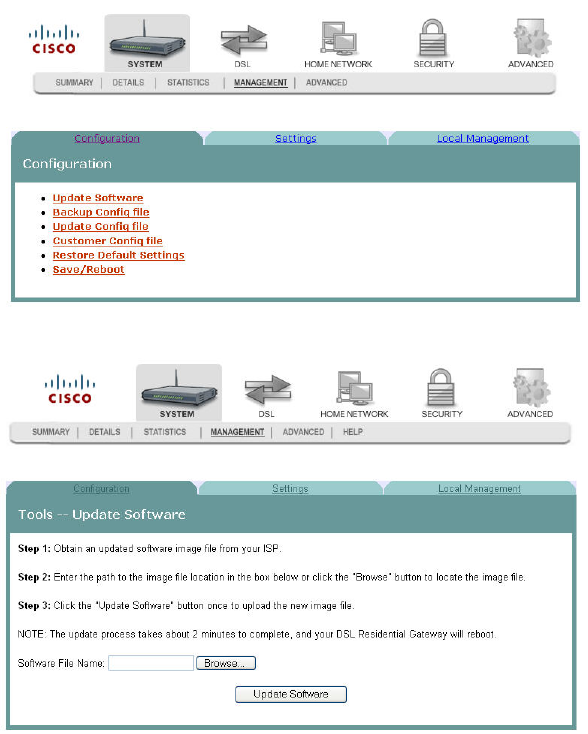
Updating Software
To update the software for the residential gateway, complete the following steps.
1 Click System on the main screen.
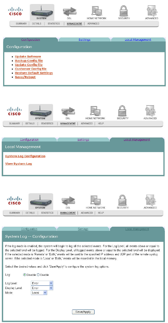
2 Click Management. The Configuration screen opens with the Configuration tab
in the forefront.
3 Click Update Software. The Tools Update Software screen opens.
4 In the Software File Name field, click Browse to locate the software image file.
5 Click Update Software to update the software of your residential gateway with
the new version. The residential gateway loads the new software and reboots
when the software update is complete.
Cha
p
te
r
3 Confi
g
uration and O
p
eration
38 4020210
Rev
A
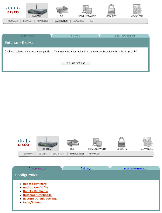
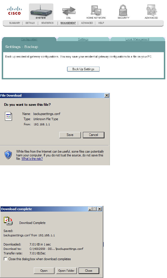
Settings Backup
The Settings - Backup screen allows you to back up the residential gateway
configuration and save it to disk.
Path: System > Management > Configuration > Back Up Config File
Backing Up Configuration Settings
To back up the configuration settings for the residential gateway, complete the
following steps.
1 Click System on the main screen.
2 Click Management. The Configuration screen opens with the Configuration tab
in the forefront.
Settings Backup
4020210 Rev
A
39
3 Click Backup Config file. The Settings - Backup screen opens.
4 Click Back Up Settings. The following screen is displayed.
5 Click Save. The system prompts you to select a location to store the backup.
6 Select a location and type in a file name.
7 Click Save to save a backup of the configuration. The system displays a message
when the download of the file is complete.
Cha
p
te
r
3 Confi
g
uration and O
p
eration
40 4020210
Rev
A
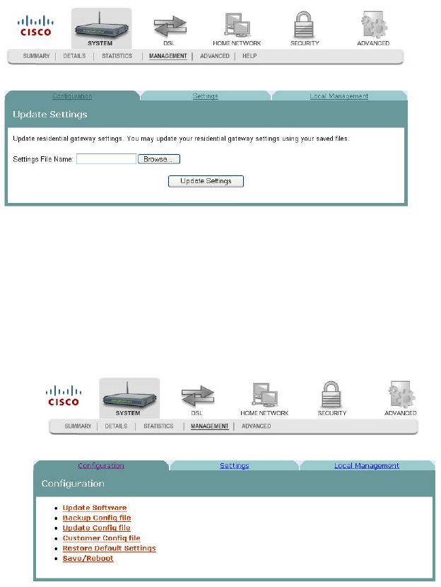
Update Settings
The Update Settings screen allows you to update the settings for the residential
gateway from a source file. We recommend that you use this feature if you want to
set up multiple residential gateways with a similar configuration.
Path: System > Management > Configuration > Update Config File
Updating Configuration Settings
To update the configuration settings for the residential gateway, complete the
following steps.
1 Click System on the main screen.
2 Click Management. The Configuration screen opens with the Configuration tab
in the forefront.
Update Settings
4020210 Rev
A
41
3 Click Update Config file. The Update Settings screen opens.
4 In the Settings File Name field, enter the name of the configuration file that you
want to use to update your settings. You can click Browse to locate the file.
5 Click Update Settings to update the configuration of the residential gateway.
6 Wait a few minutes while the system reboots the residential gateway. The new
configuration takes effect after the residential gateway reboots.
Cha
p
te
r
3 Confi
g
uration and O
p
eration
42 4020210
Rev
A
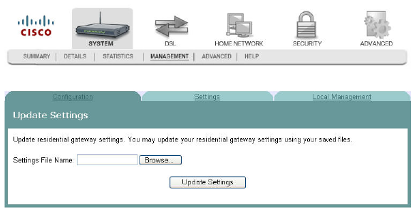
Customer Configuration File
You can upload a previously saved configuration file to be the device's default
factory settings. When you upload this file, the device will be reset to your
customized configuration file instead of the factory default configuration file. The
customer configuration file contains specific settings for your system.
Note: If you need to revert to the factory default settings, you can press the Restore
Default Settings button on the screen or the Reset button on the device. For more
information, see Restore Default Settings (on page 44).
Path: System > Management > Configuration > Update Config File
1 Click System on the main screen.
2 Click Management. The Configuration screen opens with the Configuration tab
in the forefront.
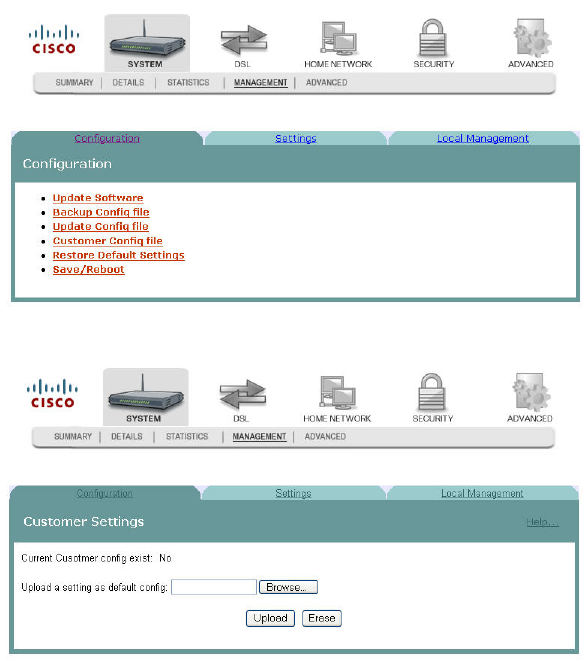
3 Click Customer Config file. The Customer Settings screen opens.
4 Click Browse to select the configuration file that you have previously saved.
Customer Configuration File
4020210 Rev
A
43
5 Click Upload to upload your configuration file. You may also delete your
uploaded configuration file by pressing the Erase button on the screen.
Notes:
When you delete your uploaded customer config file by clicking Erase, the
system reverts to the device's original default factory settings. If you do not
erase the uploaded customer config file, the system will not revert to the
device's original default factory setting when you press Restore Default
Settings or click the Reset button on the device. If the uploaded customer
config file exists, the system will reset to the new setting when you click
Restore Default Settings or the Reset button on the device. The new setting in
the customer config file is the default config settings now after you uploaded
the customer config file.
Your current configuration will not be deleted when you upload your
configuration file. Please do not confuse this with the Update Config File
utility.
Cha
p
te
r
3 Confi
g
uration and O
p
eration
44 4020210
Rev
A
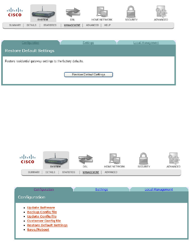
Restore Default Settings
The Restore Default Settings screen allows you to restore the residential gateway
configuration to the default settings.
Note: You can also reset the device by inserting a sharp instrument, such as a paper
clip, in the reset area on the back of the residential gateway.
Path: System > Management > Configuration > Restore Default Settings
Restoring the Configuration to the Default Settings
To restore the configuration to the default settings, complete the following steps.
1 Click System on the main screen.
2 Click Management. The Configuration screen opens with the Configuration tab
in the forefront.
Restore Default Settings
4020210 Rev
A
45
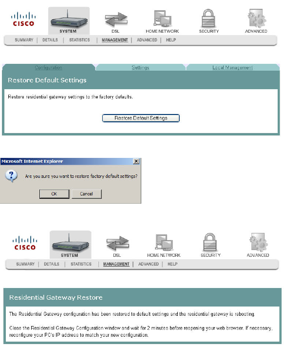
3 Click Restore Default Settings. The Tools Restore Default Settings screen opens.
4 Click Restore Default Settings. The system displays the following prompt:
5 Click OK. The system displays the following message:
6 Follow the on-screen instructions to restore the default settings.
Cha
p
te
r
3 Confi
g
uration and O
p
eration
46 4020210
Rev
A
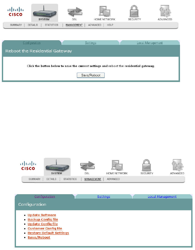
Saving the Configuration for the Residential
Gateway
The Reboot the Residential Gateway screen allows you to save any configuration
changes and to reboot the router to make the changes take effect.
Path: System > Management > Configuration > Restore Default Settings >
Save/Reboot
Saving the Configuration and Rebooting the Residential Gateway
To save any configuration changes and to reboot the router to make the changes take
effect, complete the following steps.
1 Click System on the main screen.
2 Click Management. The Configuration screen opens with the Configuration tab
in the forefront.
Saving the Configuration for the Residential Gateway
4020210 Rev
A
47
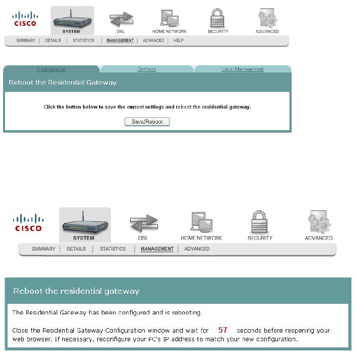
3 Click Save/Reboot. The system displays the following message:
4 Follow the instructions on the screen to save the configuration and to reboot the
router. The residential gateway displays the following message shown below.
The System Summary screen opens when the residential gateway has finished
rebooting. The new settings are displayed.
Cha
p
te
r
3 Confi
g
uration and O
p
eration
48 4020210
Rev
A
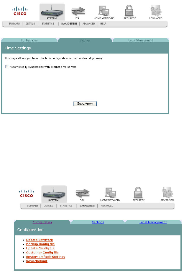
Time Settings
The Time Settings screen allows you to synchronize the time for the residential
gateway with a network-based time server.
Path: System > Management > Settings > Internet Time
Synchronize with Internet Time
To synchronize the time for the residential gateway with the Internet time, complete
the following steps.
1 Click System on the main screen.
2 Click Management. The Configuration screen opens with the Configuration tab
in the forefront.
Time Settings
4020210 Rev
A
49
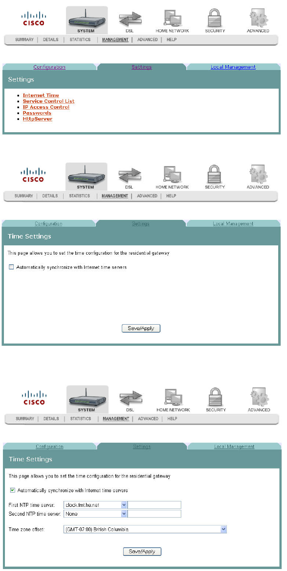
3 Click the Settings tab. The Settings screen opens.
4 Click Internet Time. The Time Settings screen opens.
5 Check the box Automatically synchronize with Internet time servers. The Time
Settings screen opens with populated fields.
6 In the First NTP time server field, select a time server from the drop-down list. If
you select Other, enter the name of the server in the blank field.
Cha
p
te
r
3 Confi
g
uration and O
p
eration
50 4020210
Rev
A
7 In the Second NTP time server field, select a time server from the drop-down list.
If you select Other, enter the name of the server in the blank field.
8 In the Time zone offset field, select the time zone specific to your area.
9 Click Save/Apply.
Service Control
4020210 Rev
A
51
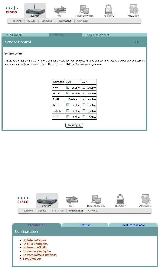
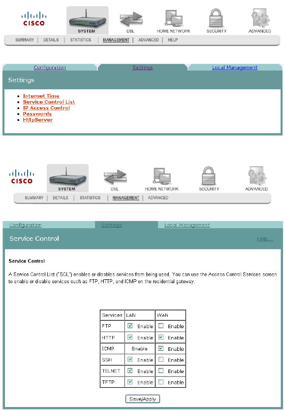
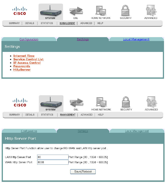
Service Control
The Service Control screen allows you to enable or disable services such as FTP,
HTTP, and ICMP on the residential gateway.
Path: System > Management > Settings > Service Control List
Enabling or Disabling Services
To enable or disable services on the residential gateway, complete the following
steps.
1 Click System on the main screen.
2 Click Management. The Configuration screen opens with the Configuration tab
in the forefront.
Cha
p
te
r
3 Confi
g
uration and O
p
eration
52 4020210
Rev
A
3 Click the Settings tab. The Settings screen opens.
4 Click Service Control List. The Service Control screen opens.
5 To enable or disable a service, do the following:
To enable a service, select the check box next to the service you want to
enable. A check box with a check indicates that the service is enabled.
To disable a service, de-select the check box next to the service you want to
disable. A check box without a check indicates that the service is disabled.
6 Click Save/Apply to enable or disable the selected services.
IP Access Control
4020210 Rev
A
53
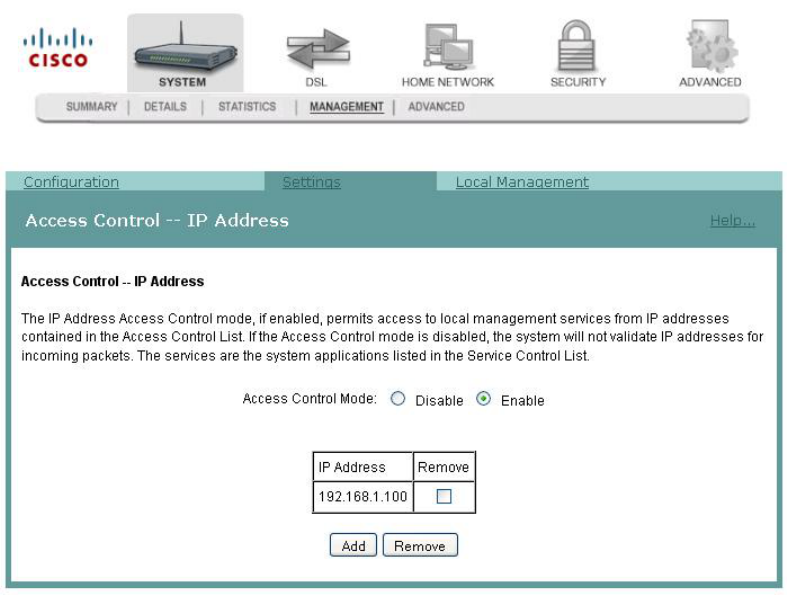
IP Access Control
The IP Address Access Control mode, if enabled, permits access to local
management services from IP addresses contained in the Access Control List. If the
Access Control mode is disabled, you cannot configure the residential gateway from
non-local IP addresses. For example, you can use this feature to prevent a remote site
from configuring the residential gateway. The services are the system applications
listed in the Service Control List.
Path: System > Management > Settings > IP Access Control
Adding IP Address Access Control
To add IP address access control, complete the following steps.
1 Click System on the main screen. The System Summary screen opens by default.
Cha
p
te
r
3 Confi
g
uration and O
p
eration
54 4020210
Rev
A
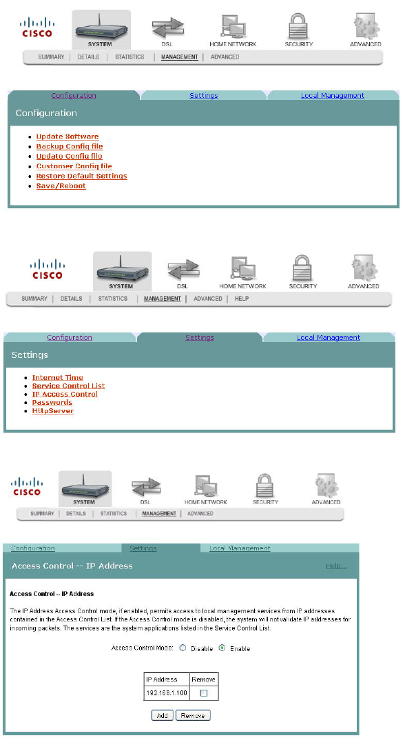
2 Click Management. The Configuration screen opens with the Configuration tab
in the forefront.
3 Click the Settings tab. The Settings screen opens.
4 Click IP Access Control. The Access Control -- IP Address screen opens.
IP Access Control
4020210 Rev
A
55
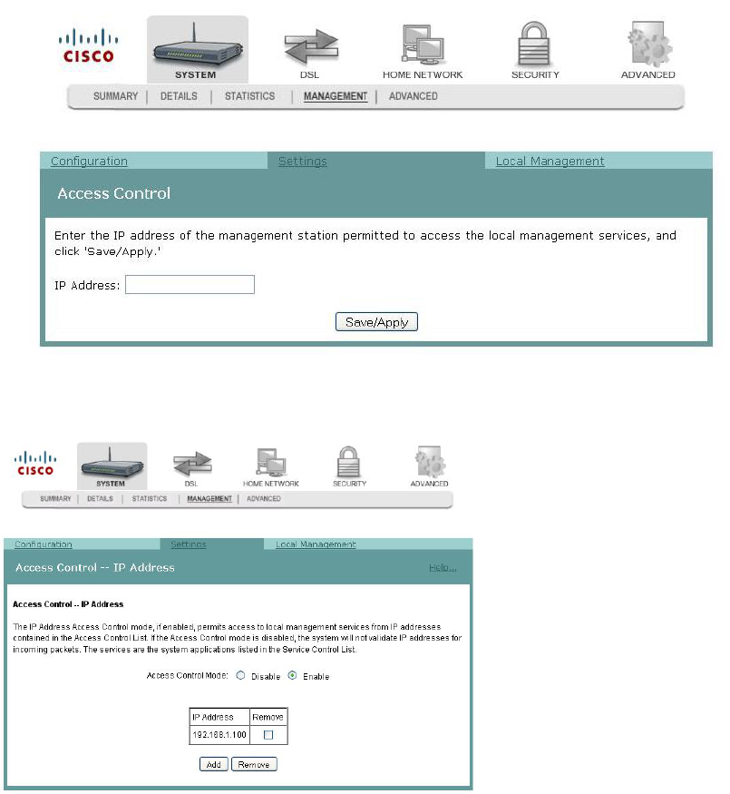
5 Click Add. The Access Control screen opens. In the IP Address field, enter the IP
address of the management station that you want to allow access to the local
management services.
6 Click Save/Apply to allow access for the IP address you entered.
7 Enable the Access Control Mode as shown in the following screen.
Cha
p
te
r
3 Confi
g
uration and O
p
eration
56 4020210
Rev
A
Password Access to the Residential Gateway
Access to the residential gateway is controlled through three user accounts:
admin. Allows unrestricted access to change and view the configuration of the
residential gateway. This login allows access to privileged information.
support. Allows an ISP technician to access your residential gateway for
maintenance and to run diagnostics
user. Allows access to view configuration settings and statistics, as well as, to
update the residential gateway's software.
The admin login provides access to all screens (including privileged information) for
the residential gateway. The support login and user login provide access to only a
subset of the screens provided to the admin login.
Path: System > Management > Settings > Passwords
Password Access to the Residential Gateway
4020210 Rev
A
57
Creating Passwords
To create passwords for the residential gateway, complete the following steps.
1 Click System on the main screen.
2 Click Management. The Configuration screen opens with the Configuration tab
in the forefront.
3 Click the Settings tab. The Settings screen opens.

Cha
p
te
r
3 Confi
g
uration and O
p
eration
58 4020210
Rev
A
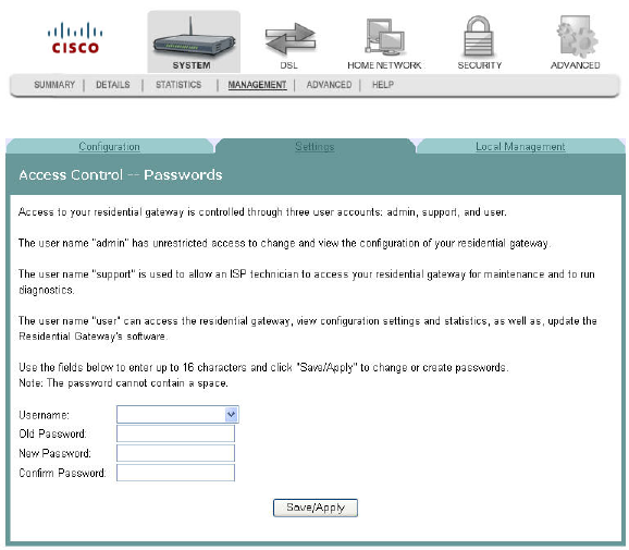
4 Click Passwords. The Access Control -- Passwords screen opens.
5 In the Username field from the drop-down list, select the type of password you
are creating: admin, support, or user. The default user name is admin.
6 In the Old Password field, enter the old password. The maximum character
length is 16 characters, and passwords cannot contain a space. The default
password is admin.
7 In the New Password field, enter the new password. The maximum character
length is 16 characters, and passwords cannot contain a space.
8 In the Confirm Password field, enter the new password again to confirm your
entry.
9 Click Save/Apply to save the password.
Tip: Another quick way to change passwords is to go to the System (home) page.
Scroll down to the last option and click Password Setting. A popup window
opens as shown below. Use this screen to enter your new passwords.
HTTP Server Port
4020210 Rev
A
59
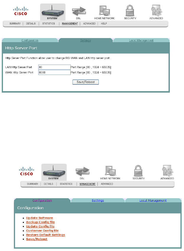
HTTP Server Port
The HTTP Server Port screen allows you to specify the TCP port for the HTTP server
on both the LAN and WAN interfaces.
Path: System > Management > Settings > HttpServer
Modifying the HTTP Server Ports
To modify the HTTP Server ports, complete the following steps.
1 Click System on the main screen.
2 Click Management. The Configuration screen opens with the Configuration tab
in the forefront.
Cha
p
te
r
3 Confi
g
uration and O
p
eration
60 4020210
Rev
A
3 Click the Settings tab. The Settings screen opens.
4 Click HttpServer. The Http Server Port opens.
5 In the LAN Http Server Port field, enter the port number for the HTTP server
from the LAN side.
6 In WAN Http Server Port field, enter the port number for the HTTP server from
the WAN side.
System Log Configuration
4020210 Rev
A
61
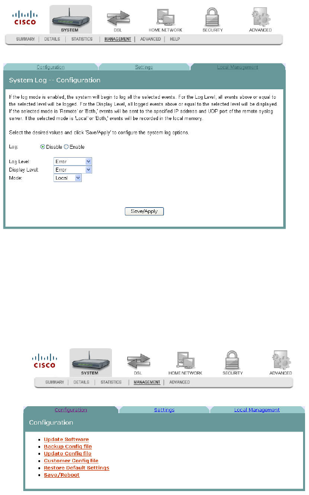
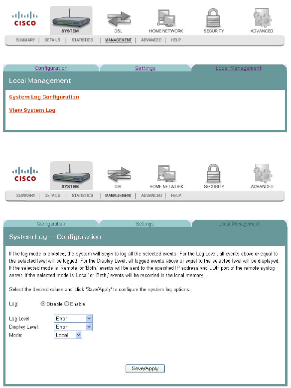
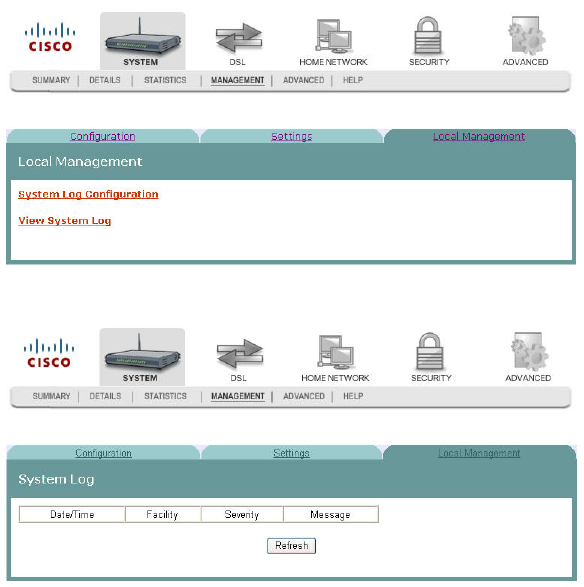
System Log Configuration
The System Log -- Configuration screen allows you to log all the selected events on
the residential gateway. For example, a failed login is an event that you can select.
Path: System > Management > Local Management > System Log Configuration
Logging Events
To log selected events, complete the following steps.
1 Click System on the main screen.
2 Click Management. The Configuration screen opens with the Configuration tab
in the forefront.
Cha
p
te
r
3 Confi
g
uration and O
p
eration
62 4020210
Rev
A
3 Click the Local Management tab. The Local Management screen opens.
4 Click System Log Configuration. The System Log Configuration screen opens.
5 Do you want to enable the logging of events?
If yes, in the Log field select Enable and go to step 6.
If no, in the Log field, select Disable and click Save/Apply to turn off
logging. You have completed this procedure.
System Log Configuration
4020210 Rev
A
63
6 In the Log Level field, select the level of events that you want to log from the
following options. All events above or equal to the selected level will be logged.
Emergency
Alert
Critical
Error
Warning
Notice
Informational
Debugging
7 In the Display Level field, select the level of the logged events that you want to
display from the following options. All logged events above or equal to the
selected level will be displayed.
Emergency
Alert
Critical
Error
Warning
Notice
Informational
Debugging
8 Select the mode for the logging from the following options. If the selected mode
is "remote" or "both," events are sent to the specified IP address and UDP port of
the remote syslog server. If the selected mode is "local" or "both," events are
recorded in the local memory.
Local. Events are logged in memory. You must log in to the device to display
the events.
Remote. Events log is sent to a remote server (syslog server).
Both. Events are logged in memory and are sent to the remote server.
9 Click Save/Apply to start logging events.
Disabling Logging
To disable the logging function, complete the following steps.
1 Click System on the main screen.
Cha
p
te
r
3 Confi
g
uration and O
p
eration
64 4020210
Rev
A
2 Click Management. The Configuration screen opens with the Configuration tab
in the forefront.
3 Click the Local Management tab. The Local Management screen opens.
4 Click System Log Configuration. The System Log Configuration screen opens.
5 In the Log field, click Disable.
System Log Configuration
4020210 Rev
A
65
6 In the Log Level field, select from the following options to indicate the level of
alarms to be logged:
Emergency
Alert
Optical
Error
Warning
Notice
Informational
Debugging
7 In the Display Level field, select from the following options to indicate the level
of alarms that you want displayed:
Emergency
Alert
Optical
Error
Warning
Notice
Informational
Debugging
8 In the Mode field, select from the following options to indicate the location to
store the logs.
Local. Store on the residential gateway.
Remote. Store on a remote log server.
Both. Store on the residential gateway and on the remote log server.
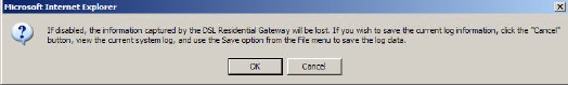
9 Click Save/Apply. The following prompt appears alerting you that you will lose
any information captured by the residential gateway:
10 Are you sure you want to disable logging and lose the captured data?
If yes, click OK to turn off logging.
If no, click Cancel.
Cha
p
te
r
3 Confi
g
uration and O
p
eration
66 4020210
Rev
A
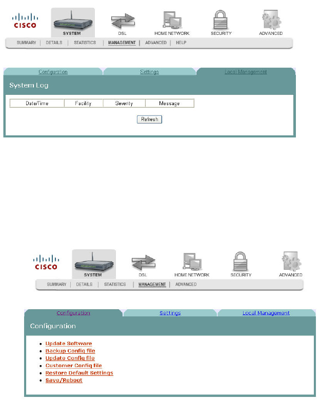
System Logs
The System Log screen allows you to view the logs of activity for the residential
gateway.
Path: System > Management > Local Management > View System Log
Viewing System Logs
To view the system log for the residential gateway, complete the following steps.
1 Click System on the main screen.
2 Click Management. The Configuration screen opens with the Configuration tab
in the forefront.
System Logs
4020210 Rev
A
67
3 Click the Local Management tab. The Local Management screen opens.
4 Click View System Log. The System Log screen opens.
5 Review the log entries on the screen.
6 Click Refresh to refresh the system log.
Cha
p
te
r
3 Confi
g
uration and O
p
eration
68 4020210
Rev
A
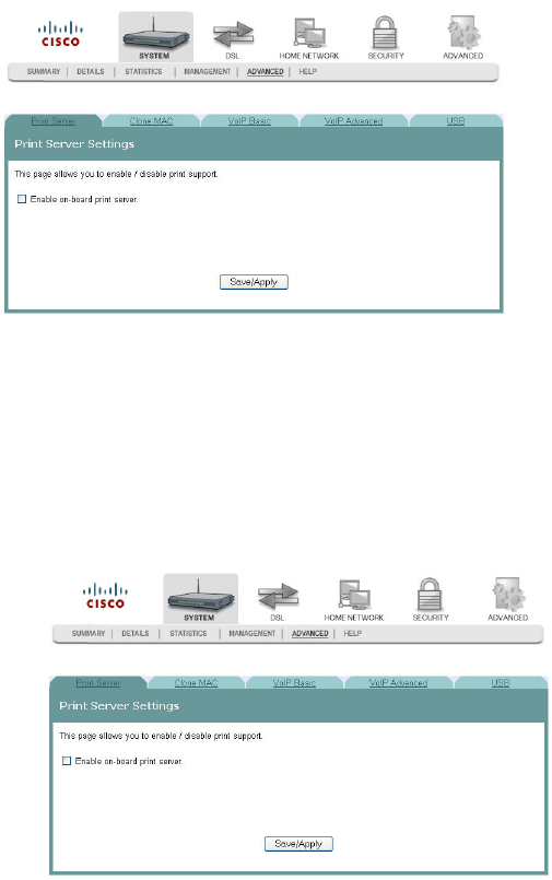
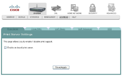
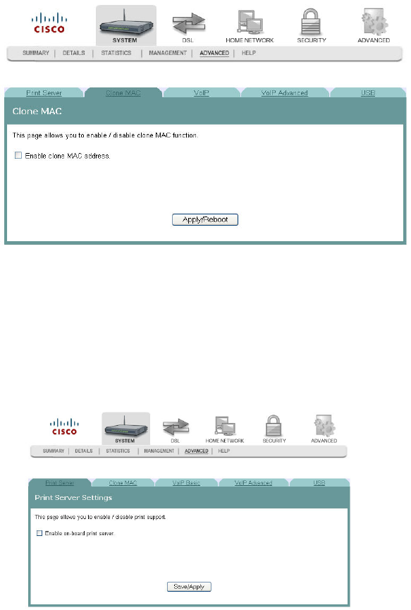
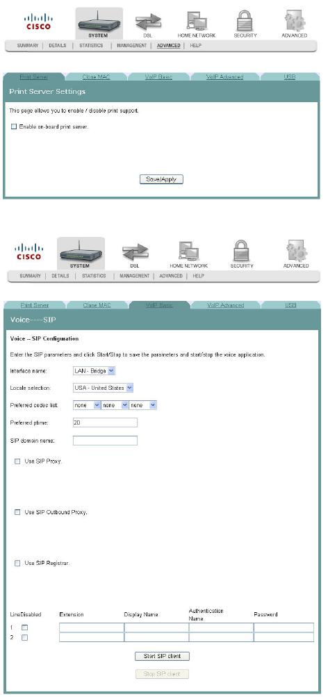
Print Server Settings
The Print Server Setting screen allows you to enable or disable printer support from
the USB connection.
Path: System > Advanced > Print Server
Enabling the Print Server
To enable the print server, complete the following steps.
1 Click System on the main screen.
2 Click the Advanced tab. The Print Server settings screen opens with the Print
Server tab in the forefront.
Print Server Settings
4020210 Rev
A
69
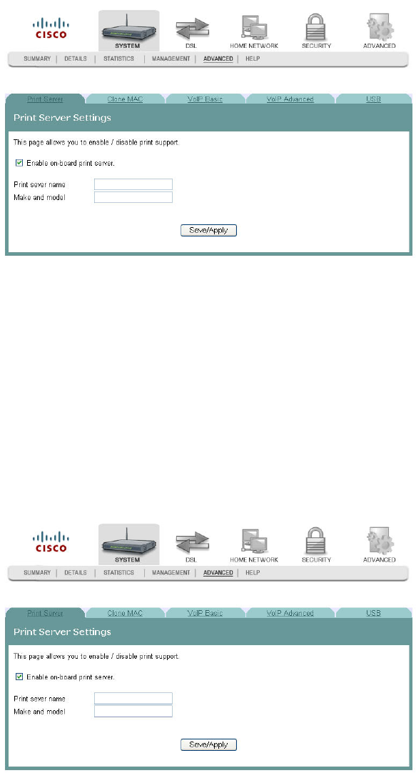
3 Check the Enable on-board print server check box. The screen populates with
more fields.
4 In the Print server name field, enter the name of the print server you want to
enable.
5 In the Make and model field, enter the make and model of the printer.
6 Click Save/Apply to enable the print server.
Disabling the Print Server
To disable the print server, complete the following steps.
1 Click System on the main screen.
2 Click the Advanced tab. The Print Server settings screen opens with the Print
Server tab in the forefront.
Cha
p
te
r
3 Confi
g
uration and O
p
eration
70 4020210
Rev
A
3 Clear the Enable on-board print server check box. The screen refreshes and the
fields for entering print server name, make, and mode are removed from the
screen.
4 Click Save/Apply to disable the print server.
Clone MAC Addresses
4020210 Rev
A
71
Clone MAC Addresses
The Clone MAC screen allows you to enable or disable the clone MAC function. The
Clone MAC function allows you to clone MAC addresses so that the residential
gateway assumes the MAC address of an attached device or a user-specified MAC
address.
Path: System > Advanced > Clone MAC
Enabling the Clone MAC Function
To enable the Clone MAC function, complete the following steps.
1 Click System on the main screen.
2 Click the Advanced tab. The Print Server settings screen opens with the Print
Server tab in the forefront.
Cha
p
te
r
3 Confi
g
uration and O
p
eration
72 4020210
Rev
A
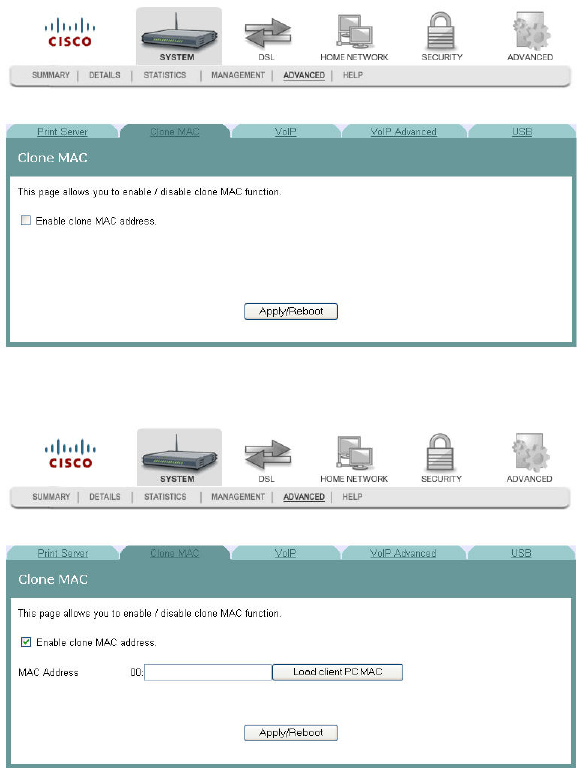
3 Click the Clone MAC tab.
4 Select the Enable clone MAC address check box. The screen populates with
more fields.
5 In the MAC Address field, enter the MAC address that you want to clone. You
can also click Load client PC MAC to locate an address you want to clone.
6 Click Apply/Reboot to clone the MAC address. The residential gateway reboots
and assumes the MAC address you have specified.
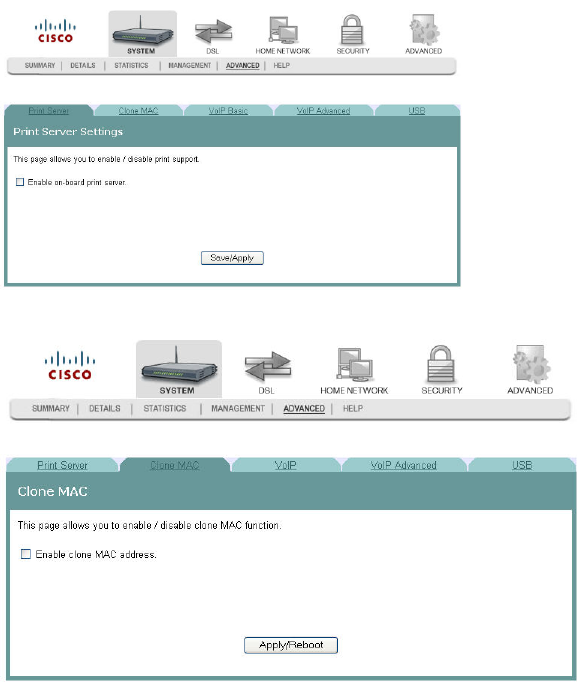
Disabling the Clone MAC Function
To disable the Clone MAC function, complete the following steps.
1 Click System on the main screen.
Clone MAC Addresses
4020210 Rev
A
73
2 Click the Advanced tab. The Print Server settings screen opens with the Print
Server tab in the forefront.
3 Click the Clone MAC tab.
4 Uncheck the Enable clone MAC address check box. The screen refreshes and the
field for entering the MAC address is removed from the screen.
5 Click Apply/Reboot to disable the Clone MAC function.
Cha
p
te
r
3 Confi
g
uration and O
p
eration
74 4020210
Rev
A
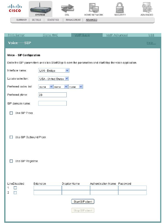
Voice SIP Basic Configuration
The Voice ---- SIP screen allows you to enter and save the session initiation protocol
(SIP) parameters and to start and stop the voice application.
Path: System > Advanced > VoIP Basic
Setting Up VoIP
To enter the VoIP parameters, complete the following steps.
1 Click System on the main screen.
Voice SIP Basic Configuration
4020210 Rev
A
75
2 Click Advanced. The Print Server Settings screen opens with the Print Server tab
in the forefront.
3 Click the VoIP Basic tab. The Voice ---- SIP screen opens.
4 In the Interface name field, select the interface you want to use for VoIP.
5 In the Locale selection field, select the country where you are located.
Cha
p
te
r
3 Confi
g
uration and O
p
eration
76 4020210
Rev
A
6 In the Preferred codec list field, select one of the following codec values:
Note: If you want to indicate an order of preference, enter a codec value for each
column.
G711U
G711A
G723
G726
G729
BV16
iLBC
7 In the Preferred ptime field, enter the time in seconds.
8 In the SIP domain name field, enter the domain name for the session initiation
protocol (SIP) server.
9 Do you wish to use SIP Proxy?
If yes, check the Use SIP Proxy check box. The SIP Proxy and the SIP Proxy
port fields appear. Enter the SIP proxy server domain name or IP address
and the SIP Proxy port.
If no, make sure the Use SIP Proxy check box is unchecked.
10 Do you wish to use an SIP Outbound proxy?
If yes, check the Use SIP Outbound Proxy check box. The SIP Outbound
Proxy and the SIP Outbound Proxy port fields appear. Enter the SIP
outbound proxy server domain name or IP Address and the SIP outbound
proxy port.
If no, make sure the Use SIP Outbound Proxy check box is unchecked
11 Do you wish to use SIP Registrar?
If yes, check the Use SIP Registrar check box. The SIP Registrar and the SIP
Registrar port fields appear. Enter the SIP registrar's domain name or IP
address and the SIP registrar's port.
If no, make sure the Use SIP Registrar check box is unchecked.
12 Do you want to disable the line?
If yes, check the Line Disabled checkbox to disable the line and prevent the
phone connecting to this line from working.
If no, make sure the Line Disabled checkbox is unchecked. For normal
operation, the Line Disabled Checkbox should be unchecked.
13 In the Extension field, enter the phone number (extension) for the VoIP line.
14 In the Display Name field, enter the name that you want to be displayed.
15 In the Authentication Name field, enter the name that you want to be
authenticated.
Voice SIP Basic Configuration
4020210 Rev
A
77
16 In the Password field, enter the password for the extension. This allows you to
authenticate the phone number.
17 Do you want to activate the line?
If yes, click Start SIP client to save your settings and to activate the line.
If no, click Stop SIP client to deactivate the line.
Cha
p
te
r
3 Confi
g
uration and O
p
eration
78 4020210
Rev
A
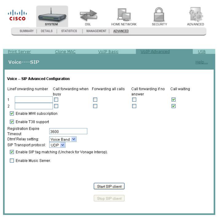
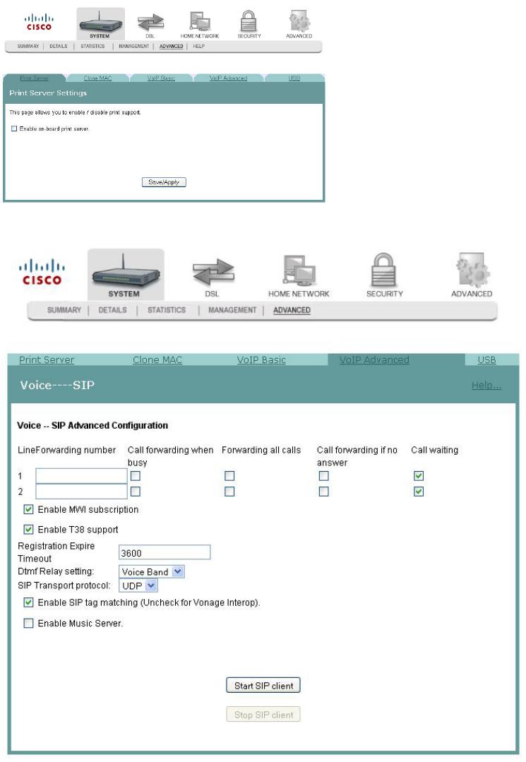
Voice SIP Advanced Configuration
The Voice----SIP screen allows you to configure the more advanced VoIP features,
such as call forwarding.
Path: System > Advanced > VoIP Advanced
Setting Up Advanced VoIP Features
To set up the advanced VoIP features, complete the following steps.
1 Click System on the main screen.
Voice SIP Advanced Configuration
4020210 Rev
A
79
2 Click Advanced. The Print Server Settings screen opens with the Print Server tab
in the forefront.
3 Click the VoIP Advanced tab. The Voice ---- SIP screen opens.
Cha
p
te
r
3 Confi
g
uration and O
p
eration
80 4020210
Rev
A
4 In the LineForwarding number field, enter the number to which you want to
forward calls. Configure how calls are forwarded to this line using the following
options:
a Check the Call forwarding when busy check box if you want to forward this
line to another number when this line is busy.
b Check the Forwarding all calls check box if you want to forward all calls to
this line.
c Check the Call forwarding if no answer check box if you want to forward this
line if the caller receives no answer.
d Check the Call waiting check box if you want to enable call waiting for this
line.
5 Repeat step 4 for a second phone line for which you wish to forward incoming
calls.
6 Check the Enable MWI subscription check box if you want to enable the message
waiting indicator.
7 Check the Enable T38 support check box if you want to enable T38 fax support.
8 In the Registration Expire Timeout field, enter the registration expiration time of
the SIP client.
9 In the Dtmf Relay setting field, select one of the following settings:
Sip Info
RFC2833
Voice Band
10 In the SIP Transport protocol field, select the protocol you will support from the
following options:
All
TCP
UDP
TLS
11 Check the Enable SIP tag matching (Uncheck for Vonage Interop) check box if
you want to enable session initiation protocol.
12 Check the Enable Music Server check box if you want to have music playing
while callers wait.
13 Click Start SIP client or click Stop SIP client if you want to start or stop the SIP
client.
USB File List
4020210 Rev
A
81
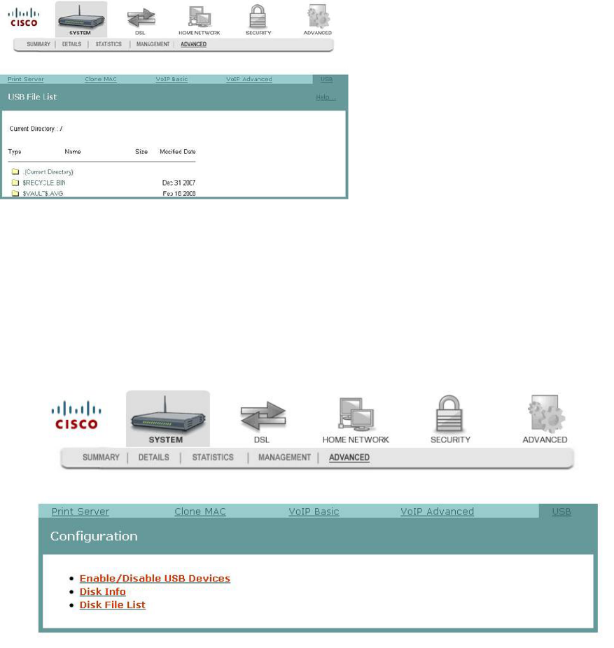
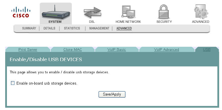
USB File List
The USB File List screen allows you to view and download the content of a USB flash
drive from any computer connected to the gateway. This feature allows your
residential gateway to act like a shared network drive.
Path: System > Advanced > USB
Enabling or Disabling USB Devices
To enable or disable a USB device, complete the following steps.
1 Click System on the main screen.
2 Click Advanced. The Print Server Settings screen opens with the Print Server tab
in the forefront.
3 Click USB. The USB Configuration screen opens.
Cha
p
te
r
3 Confi
g
uration and O
p
eration
82 4020210
Rev
A
4 Click Enable/Disable USB Devices. The Enable/Disable USB Devices screen
opens.
5 Do you wish to enable USB devices?
If yes, check the Enable on-board usb storage devices check box to enable
the USB devices. After you enable it, you can view the USB disk information
or the Disk File List on the page. You can access the files on the USB disk
drive from any LAN/WLAN PC since the files are on the network.
If no, make sure the Enable on-board usb storage devices check box is
unchecked.
6 Click Save/Apply to save your settings.

4020210 Rev
A
83
The DSL tab allows you to check the status of the DSL connection and
to modify the configuration.
Use this chapter to help you check the status of the DSL connection,
such as performance, and to modify the DSL configuration.
4 Chapter 4
DSL Configuration
In This Chapter
DSL Summary ....................................................................................... 84
DSL Statistics......................................................................................... 85
DSL Diagnostics.................................................................................... 87
DSL Settings........................................................................................... 90
DSL Advanced Settings ....................................................................... 92
ADSL Tone Settings.............................................................................. 94
Cha
p
te
r
4 DSL Confi
g
uration
84 4020210
Rev
A
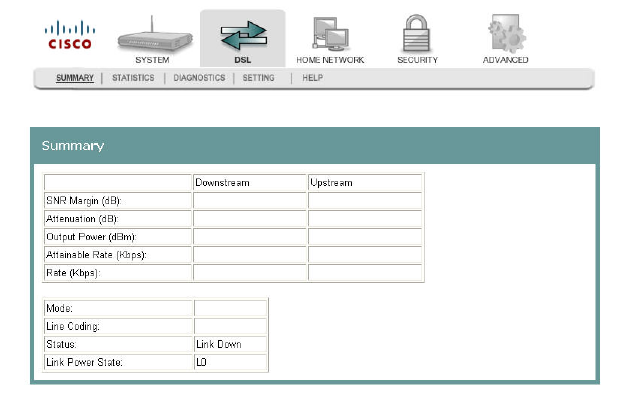
DSL Summary
The DSL Summary screen shows the DSL performance and operational
configuration of the DSL interface, such as signal to noise ratio and output power
and line coding. The DSL chip on the residential gateway automatically detects the
best method to use to communicate with the DSL access multiplexer (DSLAM). This
screen reports the results of that process.
Path: DSL > Summary
DSL Statistics
4020210 Rev
A
85
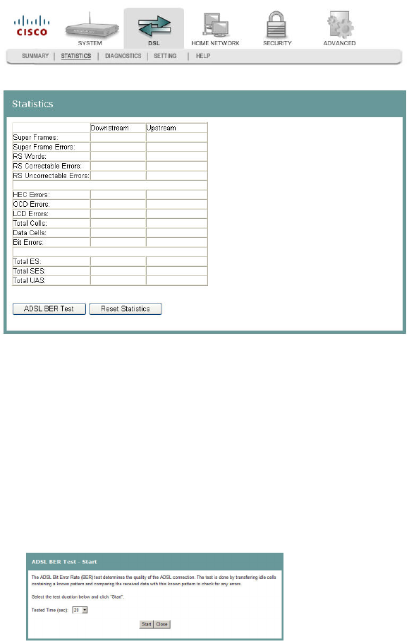
DSL Statistics
The DSL Statistics screen displays statistics for devices and interfaces on the ADSL
network. This screen shows the details of the physical layer of the DSL line such as
errors and number of cells.
Path: DSL > Statistics
Testing the Quality of the DSL Connection
The ADSL Bit Error Rate (BER) test determines the quality of the ADSL connection.
The test is done by transferring idle cells containing a known pattern and comparing
the received data with this known pattern to check for any errors.
To test for quality of the DSL connection, complete the following steps.
1 Click DSL on the main screen.
2 Click the Statistics tab. The Statistics screen opens.
3 Click ADSL BER Test. The ADSL BER Test - Start screen opens.
4 In the Tested Time (sec) field, enter the duration of the test in seconds. Values
are: 1, 5, 10, 20, 60, 120, 180, or 240 seconds.
Cha
p
te
r
4 DSL Confi
g
uration
86 4020210
Rev
A
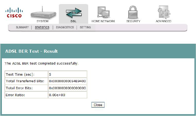
5 Click Start on the ADSL BER Test - Start screen to start the test. The result of the
ADSL BER Test appears as shown in the following example.
6 Click Close to close the popup window and return to the DSL Statistics page
Reset Statistics
To reset the statistics, complete the following steps.
1 Click DSL on the main screen.
2 Click the Statistics tab. The Statistics screen opens.
3 Click Reset Statistics on the Statistics screen. This action clears the ADSL cell
counters and sets them to zero.
DSL Diagnostics
4020210 Rev
A
87
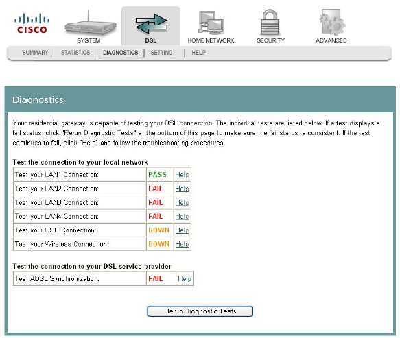
DSL Diagnostics
The Diagnostics screen shows the results of diagnostics tests that the residential
gateway performs while testing your DSL connection. The individual tests are listed
on the Diagnostics screen.
Path: DSL > Diagnostics
Running Diagnostic Tests
To run diagnostic tests for the residential gateway, complete the following steps.
1 Click DSL on the main screen.

Cha
p
te
r
4 DSL Confi
g
uration
88 4020210
Rev
A
2 Click the Diagnostics tab. The Diagnostics screen opens.
3 Click Rerun Diagnostic Tests to start the diagnostics test. The screen populates
with results such as Fail or Pass.
DSL Diagnostics
4020210 Rev
A
89
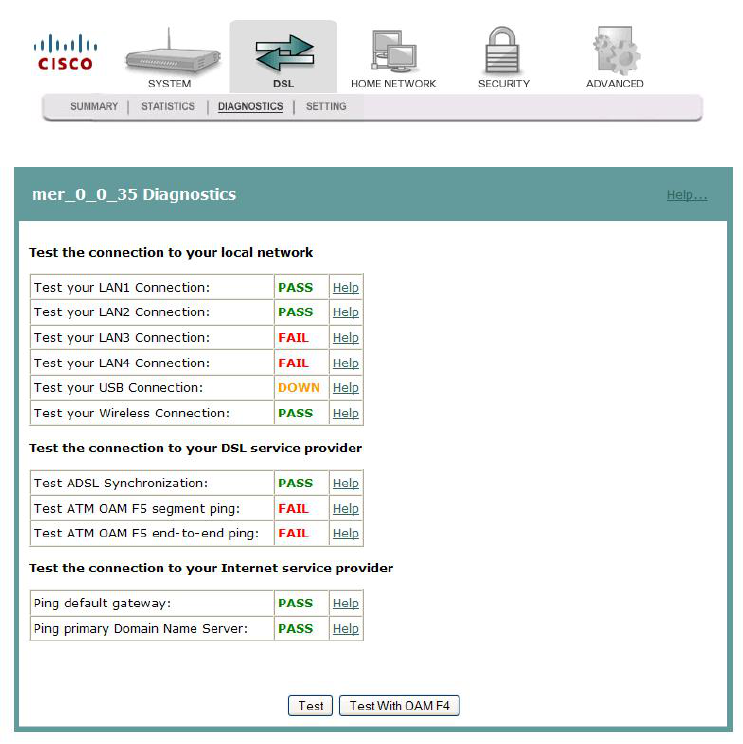
4 When you have a Permanent Virtual Circuit (PVC) up, for example an MER
connection as shown in the screen-shot below, then you can see a list of other
tests such as OAM F4/F5 or the PING test appear on the DSL Diagnostics page.
You can click Test with OAM F4 to run a OAM F4 test.
Cha
p
te
r
4 DSL Confi
g
uration
90 4020210
Rev
A
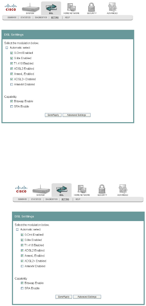
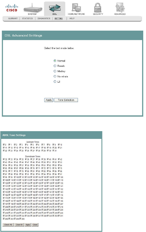
DSL Settings
The DSL Settings screen allows you to set the modulation for the residential
gateway, select a phone line pair, and to select advanced capability of the chip set:
Seamless Rate Adaptation (SRA), Bitswap Enable, and so forth.
Path: DSL > Setting
Configuring DSL Settings
To configure the DSL settings for the residential gateway, complete the following
steps.
1 Click DSL on the main screen. The Summary screen opens by default.
2 Click the Setting tab. The DSL Settings screen opens.
DSL Settings
4020210 Rev
A
91
3 Do you want to automatically select the modulation?
If yes, make sure the Automatic Select check box is checked under Select the
modulation below field. Go to step 5.
If no, uncheck the Automatic Select check box. A list of modulation types
appears.
4 Under the Select the modulation below area on the screen, select the modulation
that you want to use. You can select one or all of the following modulations:
G.Dmt Enabled
G.lite Enabled
T1.413 Enabled
ADSL2 Enabled
AnnexL Enabled
ADSL2+ Enabled
AnnexM Enabled
5 Under the Capability field, select the capability that you want to use from the
following options:
Bitswap Enable
SRA Enable
6 Click Save/Apply to save the settings.
Cha
p
te
r
4 DSL Confi
g
uration
92 4020210
Rev
A
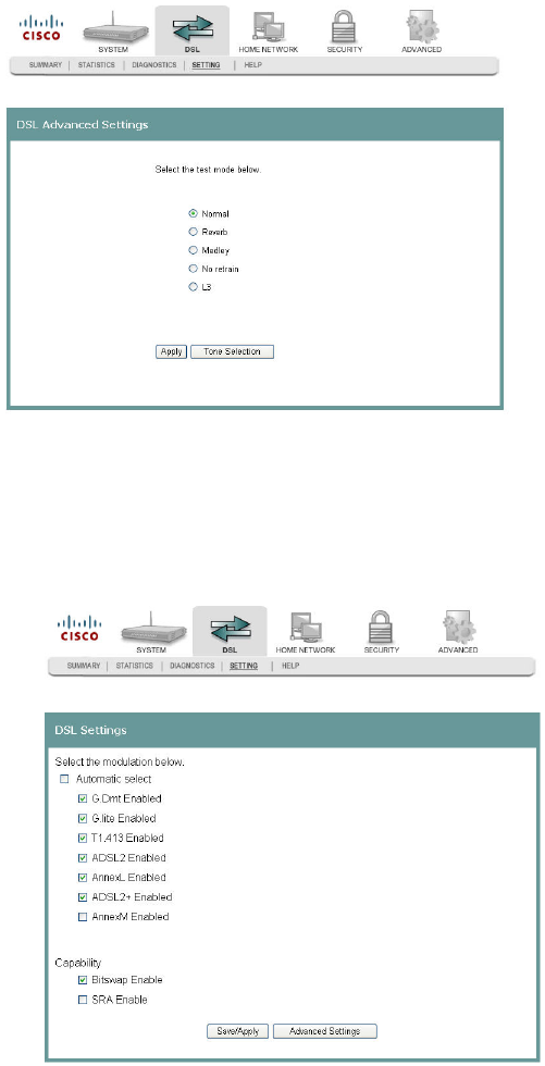
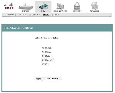
DSL Advanced Settings
The DSL Advanced Settings screen allows you to select a test mode.
Path: DSL > Setting > Advanced Settings
Configuring DSL Advanced Settings
To configure the DSL advanced settings, complete the following steps.
1 Click DSL on the main screen. The Summary screen opens by default.
2 Click the Setting tab. The DSL Settings screen opens.
DSL Advanced Settings
4020210 Rev
A
93
3 Click Advanced Settings. The DSL Advanced Settings screen opens.
4 Select the test mode from the following options:
Normal
Reverb
Medley
No refrain
L3
5 Click Apply to configure and save the advanced settings.
Cha
p
te
r
4 DSL Confi
g
uration
94 4020210
Rev
A
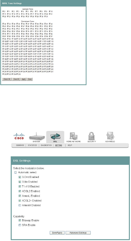
ADSL Tone Settings
The ADSL Tone Settings screen allows you to select active DSL tones or frequencies
used by the DSL transceiver.
Path: DSL > Setting > Advanced Settings > Tone Selection
Setting DSL Tones or Frequencies
To set DSL tones or frequencies, complete the following steps.
1 Click DSL on the main screen. The Summary screen opens by default.
2 Click the Setting tab. The DSL Settings screen opens.
ADSL Tone Settings
4020210 Rev
A
95
3 Click Advanced Settings. The DSL Advanced Settings screen opens.
4 Click Tone Selection. The ADSL Tone Settings screen opens.
5 Select the ADSL tone settings as follows.
To select all the tones, click Check All.
To select individual tones, click Clear All and then select the tones you want.
6 Click Apply to configure the tone settings.
7 Click Close to return to the DSL Advanced Settings screen.

4020210 Rev
A
97
The Home Network tab allows you to check the home network
configuration. You use this tab to configure and check the status of the
devices connected to your home network.
5 Chapter 5
Home Network Configuration
In This Chapter
Client Summary .................................................................................... 98
WAN Quick Setup.............................................................................. 101
LAN Setup ........................................................................................... 108
Wireless Summary.............................................................................. 112
Wireless Basic...................................................................................... 113
Wireless Security................................................................................. 120
Wireless MAC Filtering ..................................................................... 127
Wireless Bridge ................................................................................... 131
Wireless Station List ........................................................................... 133
Wi-Fi Protected Setup ........................................................................ 135
HPNA Information............................................................................. 137
HPNA Statistics Information ............................................................ 139
Cha
p
te
r
5 Home Network Confi
g
uration
98 4020210
Rev
A
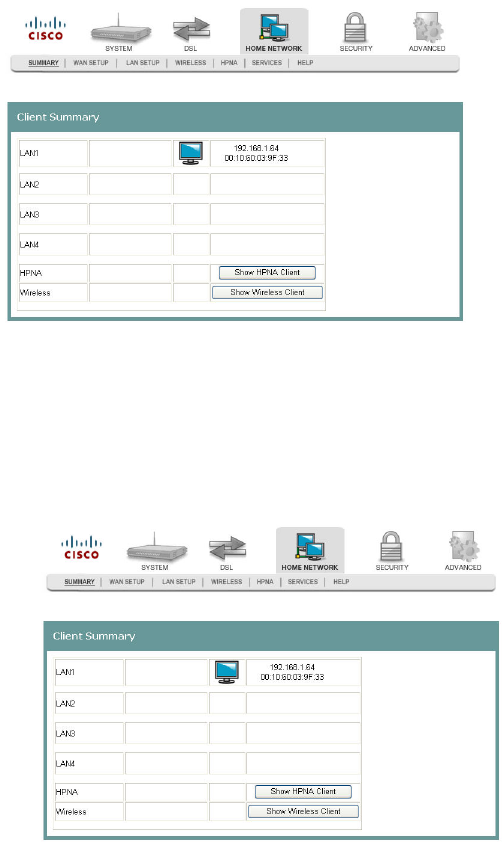
Client Summary
The Client Summary screen shows all the client devices (Wired/Wireless/HPNA)
attached to the residential gateway on the LAN side. You can click Show HPNA
Client to display the HPNA devices attached to the HPNA RF interface of the
residential gateway.
Path: Home Network > Summary > Show HPNA Client
Updating HPNA Clients
To update the HPNA clients, complete the following steps.
1 Click Home Network on the main screen.
2 Click Summary. The Client Summary screen opens.