GemTek Technology AP990625S Wireless Video Client User Manual UserMan 1 MXF AP990625S
Gemtek Technology Co., Ltd. Wireless Video Client UserMan 1 MXF AP990625S
Contents
- 1. UserMan-1_MXF-AP990625S
- 2. UserMan-2_MXF-AP990625S
- 3. UserMan (statement)_MXF-AP990625S
UserMan-1_MXF-AP990625S
Quick Reference Guide
Cisco Models VEN401 and VEN402 Video Bridge Solution
Cisco Systems, Inc. 678 277-1120
5030 Sugarloaf Parkway, Box 465447 800 722-2009
Lawrenceville, GA 30042 www.cisco.com
Cisco and the Cisco logo are trademarks or registered trademarks of Cisco and/or its affi liates in the U.S. and other countries. A listing of Cisco’s trademarks can be found at www.cisco.com/go/trademarks.
The Wi-Fi Protected Setup mark is a mark of the Wi-Fi Alliance. Wi-Fi Protected Setup is a trademark of the Wi-Fi Alliance.
Other third party trademarks mentioned are the property of their respective owners.
The use of the word partner does not imply a partnership relationship between Cisco and any other company. (1009R)
Product and service availability are subject to change without notice.
© 2011 Cisco and/or its affi liates. All rights reserved.
February 2011 Part Number 4038770 Rev A
Safety First
Your VEN401 and VEN402 come with a CD that contains a user guide with important safety information. Before installing these
devices, read the Important Safety Instructions provided in the user guide.
Open Source GNU GPL Statement
Cisco Models VEN401 and VEN402 contain(s), in part, certain free/open source software (“Free Software”) under licenses
which generally make the source code available for free copy, modi cation, and redistribution. Examples of such licenses
include all the licenses sponsored by the Free Software Foundation (e.g. GNU General Public License (GPL), GNU Lesser
General Public License (LGPL), Berkeley Software Distribution (BSD), the MIT licenses and di erent versions of the Mozilla and
Apache licenses). To nd additional information regarding the Free Software, including a copy of the applicable license and
related information, please go to: (i) for North America http://www.cisco.com/web/consumer/support/open_source.html,
or (ii) for outside North America http://www.cisco.com/web/consumer/support/open_source.html#~international. Once at
the site, search for the product listing and click on the related items identi ed. If you have any questions or problems accessing
any of the links, please contact: spvtg-external-opensource-requests@cisco.com.
Pairing a VEN402 Client Device
Complete the following steps to pair the VEN401 access point with a VEN402 client device.
Note: The VEN402 can only be paired with a VEN401.
1. Press the WPS button on the client device. The WPS LED ashes.
Important: You have 2 minutes to perform step 2.
2. Click the WPS button on the VEN401 Access Point. The WPS LED ashes. When the devices are paired, the WPS LED remains
lit for a short time.
Note: The WPS LED indicator remains o when the WPS is idle. This is a normal condition.
Pairing Other Client Devices
If you wish to pair the VEN401 access point with another client device, such as a Cisco wireless set-top, refer to the
documentation for that device for instructions.
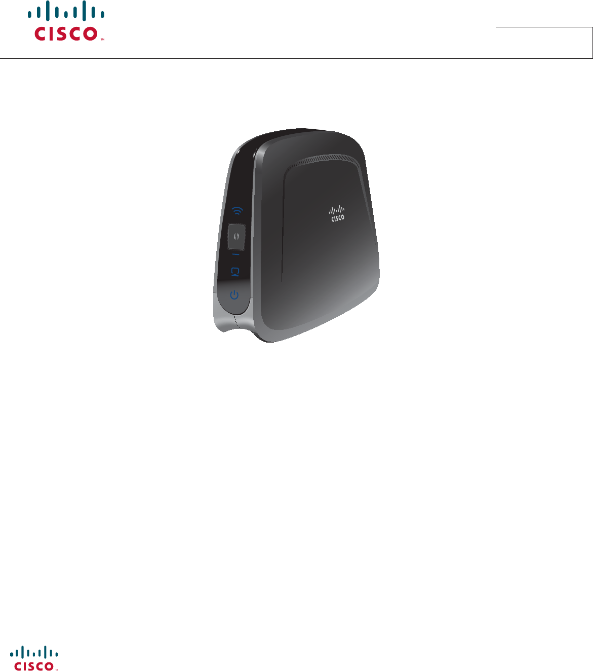
1 Wireless LED
2 Wi-Fi Protected Setup (WPS) button
3 Wi-Fi Protected Setup (WPS) LED
4 Ethernet LED
5 Power LED
Welcome
With the VEN401 and VEN402 Video Bridge Solution, you can put a set-top, digital video recorder (DVR), or digital media adapter
(DMA) almost anywhere in the home.
Simply connect the VEN401 Access Point to your residential gateway or router to make Internet access available inside your
home. Then, connect the VEN402 Client device to your set-top, DVR, or DMA. Once you pair the devices, you don’t need cables
or wall jacks to pass high-de nition video streams from the Internet to your set-top or other media devices. Follow these simple
instructions to get connected now.
The consumer support website provides news and information about this product. For more information, please refer to
http://www.cisco.com/web/consumer/support/index.html
Front Panel
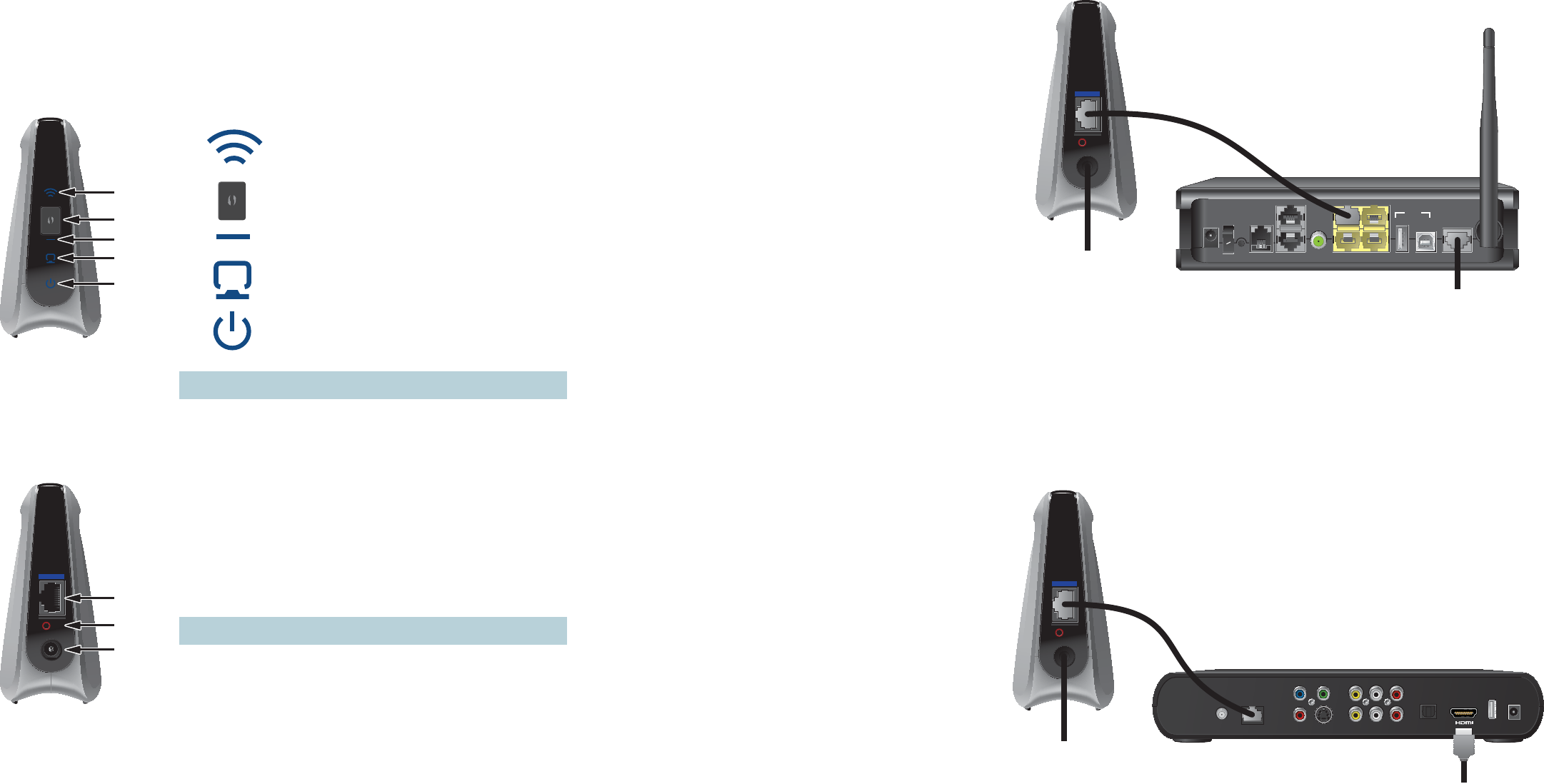
Connecting the VEN401 Access Point to a Residential Gateway or Router
1. Connect the 12 VDC Power Supply plug to the wall power outlet. Use only the power adapter provided with this product.
2. Connect the power jack to the power port on the VEN401.
3. Connect one end of the RJ-45 Ethernet cable to the Ethernet port on the VEN401.
4. Connect the other end of the RJ-45 Ethernet cable to an available Ethernet port on your residential gateway or router.
Note: This illustration may vary from the actual product.
T14853
1
2
4
3
5
1 Ethernet Port • Connects the VEN401 Access Point to a residential gateway or router
• Connects the VEN402 Client to a set-top, DVR, or DMA
2 Reset Restores factory default settings when held for more than 5 seconds
3 Power Connects device to the external 12 VDC power supply
Back Panel
12VDC
Reset
Ethernet
T14854
1
2
3
Note: This illustration may vary from the actual product.
Connecting the VEN402 Client to a Set-Top, DVR, or DMA
1. Connect the 12 VDC Power Supply plug to the wall power outlet. Use only the power adapter provided with this product.
2. Connect the power jack to the power port on the VEN402.
3. Connect one end of the RJ-45 Ethernet cable to the Ethernet port on the VEN402.
4. Connect the other end of the RJ-45 Ethernet cable to an available Ethernet port on a set-top, DVR, or DMA.
12VDC
Reset
Ethernet
T14855
To Wall
Power Outlet
ON
ON
OFF
RESET
PSTN
USB
DEVICE
PC
TEL 2
TEL 1/2
LAN 3
LAN 1
W/LAN 4
LAN 2
DSL
HPNA
POWER
To Network Jack
RJ-45
Cable
Pr
Pb Y
TO TV
(VIDEO OUT)
NETWORK S-VIDEO VIDEO
OUT
AUDIO
OUT
LR
OPTICAL POWERUSB
12VDC
Reset
Ethernet
T14856
To Wall
Power Outlet
To TV
RJ-45
Cable