GemTek Technology AP990625S Wireless Video Client User Manual Cisco Model VEN401 and VEN402 User Guide
Gemtek Technology Co., Ltd. Wireless Video Client Cisco Model VEN401 and VEN402 User Guide
Contents
- 1. UserMan-1_MXF-AP990625S
- 2. UserMan-2_MXF-AP990625S
- 3. UserMan (statement)_MXF-AP990625S
UserMan-2_MXF-AP990625S

4038769 Rev 0 1
Cisco Model VEN401 and VEN402
User Guide
Draft
DRAFT
DRAFT
Please Read
Important
Please read this entire guide. If this guide provides installation or operation
instructions, give particular attention to all safety statements included in this guide.
DRAFT
Notices
Trademark Acknowledgments
Cisco and the Cisco Logo are trademarks of Cisco Systems, Inc. and/or its affiliates
in the U.S. and other countries. A listing of Cisco's trademarks can be found at
www.cisco.com/go/trademarks.
Third party trademarks mentioned are the property of their respective owners.
The use of the word partner does not imply a partnership relationship between
Cisco and any other company. (1005R)
The Wi-Fi Protected Setup mark is a mark of the Wi-Fi Alliance. Wi-Fi Protected
Setup is a trademark of the Wi-Fi Alliance.
Disclaimer
The maximum performance for wireless is derived from IEEE Standard 802.11
specifications. Actual performance can vary, including lower wireless network
capacity, data throughput rate, range and coverage. Performance depends on many
factors, conditions and variables, including distance from the access point, volume of
network traffic, building materials and construction, operating system used, mix of
wireless products used, interference and other adverse conditions.
Publication Disclaimer
Cisco Systems, Inc. assumes no responsibility for errors or omissions that may
appear in this publication. We reserve the right to change this publication at any
time without notice. This document is not to be construed as conferring by
implication, estoppel, or otherwise any license or right under any copyright or
patent, whether or not the use of any information in this document employs an
invention claimed in any existing or later issued patent.
Copyright
© 2011 Cisco Systems, Inc. All rights reserved. Printed in the United States of America.
Information in this publication is subject to change without notice. No part of this
publication may be reproduced or transmitted in any form, by photocopy,
microfilm, xerography, or any other means, or incorporated into any information
retrieval system, electronic or mechanical, for any purpose, without the express
permission of Cisco Systems, Inc.
DRAFT
4038769 Rev 01 iii
Contents
IMPORTANT SAFETY INSTRUCTIONS v
Power Source Warning ............................................................................................. vi
Ground the Product ................................................................................................... vi
Protect the Product from Lightning ........................................................................ vi
Verify the Power Source from the On/Off Power Light ...................................... vi
Eliminate AC Mains Overloads ............................................................................... vi
Provide Ventilation and Select a Location ........................................................... vii
Protect from Exposure to Moisture and Foreign Objects ................................... vii
Service Warnings ..................................................................................................... vii
Check Product Safety .............................................................................................. vii
Protect the Product When Moving It .................................................................... vii
Compliance Information ix
Declaration of Conformity ........................................................................................ ix
Canada EMI Regulation ............................................................................................ ix
Dynamic Frequency Selection (DFS) Dual Band Frequencies .............................. x
RF Exposure Statements ............................................................................................ x
CE Compliance xi
Declaration of Conformity with Regard to the EU Directive
1999/5/EC (R&TTE Directive) ............................................................................. xi
Europe xii
National Restrictions ................................................................................................ xii
Open Source GNU GPL Statement xiii
About This Guide xv
Introduction ............................................................................................................... xv
Scope ........................................................................................................................... xv
Audience .................................................................................................................... xv
Document Version .................................................................................................... xv
DRAFT
Contents
iv 4038769 Rev 01
Installing the Devices 1
Front Panel ................................................................................................................................ 2
Back Panel ................................................................................................................................. 3
Connecting the VEN401 Access Point to a Residential Gateway or Router .................... 4
Connecting the VEN402 Client to a Set-Top, DVR, or DMA ............................................. 5
Pair Devices .............................................................................................................................. 6
Pairing a VEN402 Client Device ............................................................................... 6
Pairing Other Client Devices ..................................................................................... 6
Web-Based User Interface 7
Login .......................................................................................................................................... 8
Basic Setup ................................................................................................................................ 9
Wireless Setup ........................................................................................................................ 11
Basic Wireless Settings ............................................................................................. 11
Multiple SSID Settings ............................................................................................. 13
MAC Filter Settings .................................................................................................. 15
Security Settings ........................................................................................................ 16
Wi-Fi Protected Setup............................................................................................... 19
Set Up WPS on the VEN401 .................................................................................... 19
Associated Devices ................................................................................................... 21
Administration Setup ............................................................................................................ 22
Management Settings ............................................................................................... 22
Log Settings ............................................................................................................... 23
Diagnostics ................................................................................................................. 25
Backup Settings ......................................................................................................... 26
Factory Default Settings ........................................................................................... 27
Firmware Upgrade ................................................................................................... 27
Reboot ......................................................................................................................... 29
Status Information ................................................................................................................. 30
General System Status Information ........................................................................ 30
Wireless Status Information .................................................................................... 31
DRAFT
IMPORTANT SAFETY INSTRUCTIONS
4038769 Rev 01 v
IMPORTANT SAFETY INSTRUCTIONS
Notice to Installers
The servicing instructions in this notice are for use by qualified service personnel only. To reduce the
risk of electric shock, do not perform any servicing other than that contained in the operating
instructions, unless you are qualified to do so.
1)
Read these instructions.
2)
Keep these instructions.
3)
Heed all warnings.
4)
Follow all instructions.
5)
Do not use this apparatus near water.
6)
Clean only with dry cloth.
7)
Do not block any ventilation openings. Install in accordance with the manufacturer's
instructions.
8)
Do not install near any heat sources such as radiators, heat registers, stoves, or other
apparatus (including amplifiers) that produce heat.
9)
Do not defeat the safety purpose of the polarized or grounding-type plug. A
polarized plug has two blades with one wider than the other. A grounding-type
plug has two blades and a third grounding prong. The wide blade or the third
prong are provided for your safety. If the provided plug does not fit into your
outlet, consult an electrician for replacement of the obsolete outlet.
10)
Protect the power cord from being walked on or pinched particularly at plugs,
convenience receptacles, and the point where they exit from the apparatus.
11)
Only use attachments/accessories specified by the manufacturer.
12)
Use only with the cart, stand, tripod, bracket, or table specified by the
manufacturer, or sold with the apparatus. When a cart is used, use caution
when moving the cart/apparatus combination to avoid injury from
tip-over.
13)
Unplug this apparatus during lightning storms or when unused for long periods of
time.
DRAFT

IMPORTANT SAFETY INSTRUCTIONS
vi 4038769 Rev 01
14)
Refer all servicing to qualified service personnel. Servicing is required when the
apparatus has been damaged in any way, such as a power-supply cord or plug is
damaged, liquid has been spilled or objects have fallen into the apparatus, the
apparatus has been exposed to rain or moisture, does not operate normally, or has
been dropped.
Power Source Warning
A label on this product indicates the correct power source for this product. Operate this product only
from an electrical outlet with the voltage and frequency indicated on the product label. If you are
uncertain of the type of power supply to your home or business, consult your service provider or your
local power company.
The AC inlet on the unit must remain accessible and operable at all times.
Ground the Product
WARNING: Avoid electric shock and fire hazard! If this product connects to coaxial
cable wiring, be sure the cable system is grounded (earthed). Grounding provides
some protection against voltage surges and built-up static charges.
WARNING: Avoid electric shock and fire hazard! Do not locate an outside antenna
system in the vicinity of overhead power lines or power circuits. Touching power lines
or circuits might be fatal.
This product may contain a tuner capable of receiving off-the-air broadcasts.
Protect the Product from Lightning
In addition to disconnecting the AC power from the wall outlet, disconnect the signal inputs.
Verify the Power Source from the On/Off Power Light
When the on/off power light is not illuminated, the apparatus may still be connected to the power
source. The light may go out when the apparatus is turned off, regardless of whether it is still plugged
into an AC power source.
Eliminate AC Mains Overloads
WARNING: Avoid electric shock and fire hazard! Do not overload AC mains, outlets,
extension cords, or integral convenience receptacles. For products that require battery
power or other power sources to operate them, refer to the operating instructions for
those products.
DRAFT

IMPORTANT SAFETY INSTRUCTIONS
4038769 Rev 01 vii
Provide Ventilation and Select a Location
Remove all packaging material before applying power to the product.
Do not place this apparatus on a bed, sofa, rug, or similar surface.
Do not place this apparatus on an unstable surface.
Do not install this apparatus in an enclosure, such as a bookcase or rack, unless the installation
provides proper ventilation.
Do not place entertainment devices (such as VCRs or DVDs), lamps, books, vases with liquids, or
other objects on top of this product.
Do not block ventilation openings.
Protect from Exposure to Moisture and Foreign Objects
WARNING: Avoid electric shock and fire hazard! Do not expose this product to
dripping or splashing liquids, rain, or moisture. Objects filled with liquids, such as
vases, should not be placed on this apparatus.
WARNING: Avoid electric shock and fire hazard! Unplug this product before cleaning.
Do not use a liquid cleaner or an aerosol cleaner. Do not use a magnetic/static cleaning
device (dust remover) to clean this product.
WARNING: Avoid electric shock and fire hazard! Never push objects through the
openings in this product. Foreign objects can cause electrical shorts that can result in
electric shock or fire.
Service Warnings
WARNING: Avoid electric shock! Do not open the cover of this product. Opening or
removing the cover may expose you to dangerous voltages. If you open the cover, your
warranty will be void. This product contains no user-serviceable parts.
Check Product Safety
Upon completion of any service or repairs to this product, the service technician must perform safety
checks to determine that this product is in proper operating condition.
Protect the Product When Moving It
Always disconnect the power source when moving the apparatus or connecting or disconnecting
cables.
20090915_IP with Tuner_Safety
DRAFT
DRAFT

Compliance Information
4038769 Rev 01 ix
Compliance Information
United States FCC Compliance
This device has been tested and found to comply with the limits for a Class B digital device,
pursuant to part 15 of the FCC Rules. These limits are designed to provide reasonable
protection against such interference in a residential installation. This equipment generates,
uses, and can radiate radio frequency energy. If not installed and used in accordance with the
instructions, it may cause harmful interference to radio communications. However, there is
no guarantee that interference will not occur in a particular installation. If this equipment
does cause harmful interference to radio or television reception, which can be determined by
turning the equipment OFF and ON, the user is encouraged to try to correct the interference
by one or more of the following measures:
Reorient or relocate the receiving antenna.
Increase the separation between the equipment and receiver.
Connect the equipment into an outlet on a circuit different from that to which the
receiver is connected.
Consult the service provider or an experienced radio/television technician for help.
Any changes or modifications not expressly approved by Cisco Systems, Inc., could void the
user's authority to operate the equipment.
The information shown in the FCC Declaration of Conformity paragraph below is a
requirement of the FCC and is intended to supply you with information regarding the FCC
approval of this device. The phone numbers listed are for FCC-related questions only and not
intended for questions regarding the connection or operation for this device. Please contact your
service provider for any questions you may have regarding the operation or installation of this device.
Declaration of Conformity
This device complies with Part 15 of FCC
Rules. Operation is subject to the following
two conditions: 1) the device may not cause
harmful interference, and 2) the device must
accept any interference received, including
interference that may cause undesired
operation.
Model(s): VEN401 and VEN402
Manufactured by:
Cisco Systems, Inc.
5030 Sugarloaf Parkway
Lawrenceville, Georgia 30044 USA
Telephone: 770 236-1077
Canada EMI Regulation
This Class B digital apparatus complies with Canadian ICES-003.
Cet appareil numérique de la class B est conforme à la norme NMB-003 du Canada.
DRAFT
Compliance Information
x 4038769 Rev 01
Dynamic Frequency Selection (DFS) Dual Band Frequencies
Some configurations of this product may operate in the 5150-5250 MHz and 5470-5725 MHz
bands. If you select any channel in these frequency ranges, the product is restricted to indoor
operation only per FCC guidance. The use of this product on the affected frequencies when
outside is in non compliance of the FCC regulations and guidelines.
RF Exposure Statements
Note: This transmitter must not be co-located or operated in conjunction with any other
antenna or transmitter. This equipment should be installed and operated with a minimum
distance of 7.9 inches (20 cm) between the radiator and your body.
US
This system has been evaluated for RF exposure for humans in reference to ANSI C 95.1
(American National Standards Institute) limits. The evaluation was based in accordance with
FCC OET Bulletin 65C rev 01.01 in compliance with Part 2.1091 and Part 15.27. The minimum
separation distance from the antenna to general bystander is 7.9 inches (20 cm) to maintain
compliance.
Canada
This system has been evaluated for RF exposure for humans in reference to Canada Health
Code 6 (2009) limits. The evaluation was based on evaluation per RSS-102 Rev 4. The
minimum separation distance from the antenna to general bystander is 7.9 inches (20 cm) to
maintain compliance.
EU
This system has been evaluated for RF exposure for humans in reference to the ICNIRP
(International Commission on Non-Ionizing Radiation Protection) limits. The evaluation was
based on the EN 50385 Product Standard to Demonstrate Compliance of Radio Base Stations
and Fixed Terminals for Wireless Telecommunications Systems with basic restrictions or
reference levels related to Human Exposure to Radio Frequency Electromagnetic Fields from
300 MHz to 40 GHz. The minimum separation distance from the antenna to general
bystander is 20 cm (7.9 inches).
DRAFT

CE Compliance
4038769 Rev 01 xi
CE Compliance
Declaration of Conformity with Regard to the EU Directive 1999/5/EC
(R&TTE Directive)
This declaration is only valid for configurations (combinations of software, firmware and
hardware) supported or provided by Cisco Systems for use within the EU. The use of
software or firmware not supported or provided by Cisco Systems may result in the
equipment no longer being compliant with the regulatory requirements.
DRAFT

Europe
xii 4038769 Rev 01
Europe
The CE mark and class-2 identifier are affixed to the product and its packaging. This product
conforms to the following European directives:
-1999/5/EC
National Restrictions
This product operates in the 5 GHz Wi-Fi bands and shall only be used indoors.
Disclaimer
Cisco Systems, Inc. assumes no responsibility for errors or omissions that may
appear in this manual. We reserve the right to change this manual at any time
without notice.
Note: The VEN401 and VEN402 have disabled the 5600-5650M band by S/W to
avoid 5600-5650M band for IC certification.
Compliance Statement
Draft Note: The following paragraph is under construction until full product release.
The URL addresses are not actual addresses, but placeholder examples in this draft.
To find additional information regarding compliance information for the Cisco
VEN401 and VEN402 models, please go to: (i) for North America
http://www.cisco.com/web/consumer/support/<TBD>.html, or (ii) for outside
North America
http://www.cisco.com/web/consumer/support/<TBD>.html#~international. Once
at the site, search for the product listing and click on the related items identified. If
you have any questions or problems accessing any of the links, please contact:
spvtg-external-<TBD>-requests@cisco.com.
DRAFT
Open Source GNU GPL Statement
4038769 Rev 01 xiii
Open Source GNU GPL Statement
Cisco VEN401 and VEN402 models contain, in part, certain free/open source
software ("Free Software") under licenses which generally make the source code
available for free copy, modification, and redistribution. Examples of such licenses
include all the licenses sponsored by the Free Software Foundation (e.g. GNU
General Public License (GPL), GNU Lesser General Public License (LGPL), Berkeley
Software Distribution (BSD), the MIT licenses and different versions of the Mozilla
and Apache licenses). To find additional information regarding the Free Software,
including a copy of the applicable license and related information, please go to: (i)
for North America
http://www.cisco.com/web/consumer/support/open_source.html, or (ii) for outside
North America
http://www.cisco.com/web/consumer/support/open_source.html#~international.
Once at the site, search for the product listing and click on the related items
identified. If you have any questions or problems accessing any of the links, please
contact: spvtg-external-opensource-requests@cisco.com.
DRAFT
DRAFT
About This Guide
4038769 Rev 01 xv
About This Guide
Introduction
Congratulations on choosing the Cisco® VEN401 plus VEN402 Video Bridge Solution
for the Connected Home experience. By connecting your video devices wirelessly,
you are now free to place your televisions and video devices almost anywhere in the
home.
The small shape and unique design of the VEN401 plus VEN402 devices provide a
stylish solution without pulling wires through walls or along floorboards. The
VEN401 plus VEN402 devices are also ideal for sharing music, photos, movies, and
other files wirelessly inside the home.
Scope
This guide provides instructions and recommendations for installing and
configuring the VEN401 plus VEN402 Video Bridge Solution.
Audience
This guide is written for the home subscriber.
Document Version
This is the first formal release of this document.
DRAFT
DRAFT

4038769 Rev 01 1
Introduction
This chapter provides information to install the VEN401 Access Point
and VEN402 Client devices in home network.
1 Chapter 1
Installing the Devices
In This Chapter
Front Panel ............................................................................................... 2
Back Panel ................................................................................................ 3
Connecting the VEN401 Access Point to a Residential
Gateway or Router .................................................................................. 4
Connecting the VEN402 Client to a Set-Top, DVR, or DMA ............ 5
Pair Devices ............................................................................................. 6
DRAFT
Chapter 1 Installing the Devices
2 4038769 Rev 01
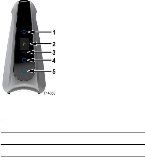
Front Panel
The front panel of your devices have the following indicators and functions:
Note: This illustration may vary from the actual product.
1
Wireless LED
2
Wi-Fi Protected Setup (WPS) button
3
Wi-Fi Protected Setup (WPS) LED
4
Ethernet LED
5
Power LED
DRAFT
Back Panel
4038769 Rev 01 3
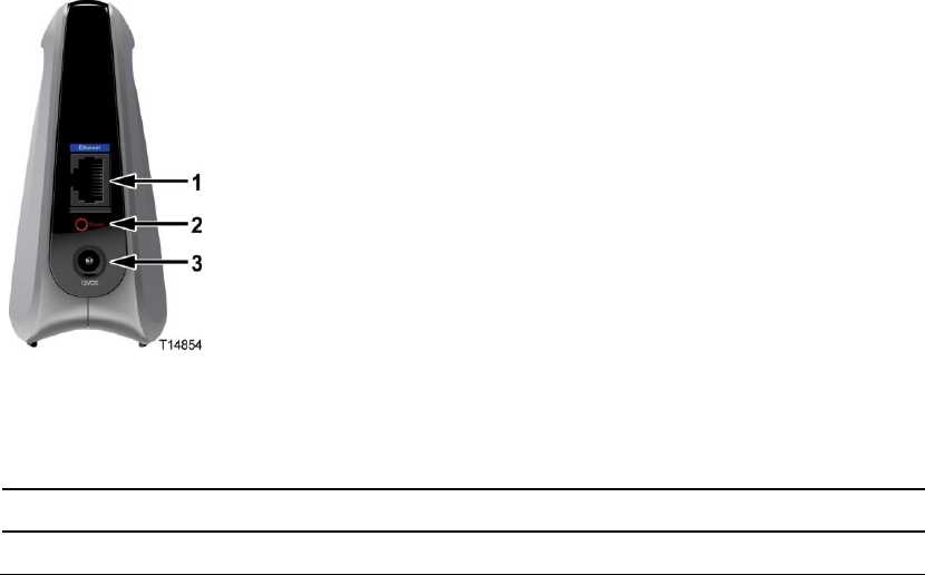
Back Panel
The back panel of your devices have the following ports and functions:
Note: This illustration may vary from the actual product.
1
Ethernet Port
Connects the VEN401 Access Point to a residential gateway or router
Connects the VEN402 Client to a set-top, DVR, or DMA
2
Reset
Restores factory default settings when held for more than 5 seconds
3
Power
Connects device to the external 12 VDC power supply
DRAFT
Chapter 1 Installing the Devices
4 4038769 Rev 01
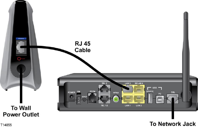
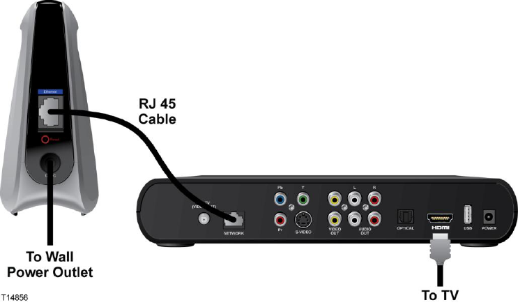
Connecting the VEN401 Access Point to a
Residential Gateway or Router
Complete the following steps to connect the VEN401 Access Point to a residential
gateway or router.
1 Connect the 12 VDC Power Supply plug to the wall power outlet. Use only the
power adapter provided with this product.
2 Connect the power jack to the power port on the VEN401.
3 Connect one end of the RJ-45 Ethernet cable to the Ethernet port on the VEN401.
4 Connect the other end of the RJ-45 Ethernet cable to an available Ethernet port on
your residential gateway or router.
DRAFT
Connecting the VEN402 Client to a Set-Top, DVR, or DMA
4038769 Rev 01 5
Connecting the VEN402 Client to a Set-Top, DVR,
or DMA
Complete the following steps to connect the VEN402 Client to a set-top, DVR, or
DMA.
1 Connect the 12 VDC Power Supply plug to the wall power outlet. Use only the
power adapter provided with this product.
2 Connect the power jack to the power port on the VEN402.
3 Connect one end of the RJ-45 Ethernet cable to the Ethernet port on the VEN402.
4 Connect the other end of the RJ-45 Ethernet cable to an available Ethernet port on
a set-top, DVR, or DMA.
DRAFT
Chapter 1 Installing the Devices
6 4038769 Rev 01
Pair Devices
Pairing a VEN402 Client Device
Complete the following steps to pair the VEN401 access point with a VEN402 client
device.
Note: The VEN402 can only be paired with a VEN401.
1 Press the WPS button on the client device. The WPS LED flashes.
Note: You have 2 minutes to perform step 2.
2 Click the WPS button on the VEN401 Access Point. The WPS LED flashes. When
the devices are paired, the WPS LED remains lit for a short time.
Note: The WPS LED indicator remains off when the WPS is idle. This is a normal
condition.
Pairing Other Client Devices
If you wish to pair the VEN401 access point with another client device, such as a
Cisco wireless set-top, refer to the documentation for that device for instructions.
DRAFT

4038769 Rev 01 7
Introduction
To facilitate in-home customization and troubleshooting, the VEN401
plus VEN402 Video Bridge Solution includes a web-based user
interface. The web-based user interface allows you to customize your
Wi-Fi security and access other configurable features.
The parameters accessed from the user interface are typically managed
by your service provider. This chapter provides information for
advanced users to manage some of the parameters for basic and
wireless setup, including wireless security. If you are not familiar with
the terms or features described in this chapter, contact your service
provider for assistance.
Notes:
The parameters discussed in this chapter can be configured for
both the VEN401 and VEN402 devices unless noted otherwise.
The illustrations in this chapter may vary from your actual
product.
2 Chapter 2
Web-Based User Interface
In This Chapter
Login ......................................................................................................... 8
Basic Setup ............................................................................................... 9
Wireless Setup ....................................................................................... 11
Administration Setup ........................................................................... 22
Status Information ................................................................................ 30
DRAFT
Chapter 2 Web-Based User Interface
8 4038769 Rev 01
Login
Complete the following steps to determine the IP address of your device and log in
to the web-based user interface for your device.
1 The VEN 401/402 receive their IP addresses via DHCP from the connected
router or gateway. Please, refer to your router or gateway documentation to
determine the IP address.
2 Open a web browser on your computer.
3 Type the DHCP-provided IP address in the URL address field and then press
Enter.
A pop-up window appears prompting you to provide login information.
4 Is this your first time logging in?
If yes, leave the Login ID field empty and type admin in the Password field.
Then, press Continue.
If no, type the ID and Password you used or saved last time you logged in.
Then, press Continue.
DRAFT
Basic Setup
4038769 Rev 01 9
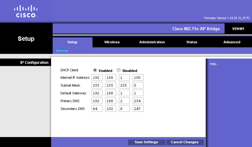
Basic Setup
Use the Setup screen to define the Internet Protocol (IP) configuration for your
device.
1 Choose your Dynamic Host Configuration Protocol (DHCP) option per the
following guidelines:
Enabled: If your network includes a DHCP server for dynamic allocation of
IP addresses, choose this option if you want DHCP to assign an IP address
and subnet mask to the device. Depending on your router, the default
gateway, primary DNS server, and secondary DNS server may also be
assigned.
Disabled: Choose this option if you want to manually enter IP configuration
information.
2 Did you select the Disabled option?
If yes, complete the fields on the screen per the following guidelines:
– Internet IP Address: If you configure the device for a static IP address,
enter that IP address.
– Subnet Mask: If you configure the device for a static IP address, enter the
subnet mask. Use the same value that is configured for the personal
computers (PCs) on your network.
– Default Gateway: If you configure the device for a static IP address, enter
the gateway IP address. Use the same value that is configured for the PCs
on your network.
DRAFT
Chapter 2 Web-Based User Interface
10 4038769 Rev 01
– Primary DNS (Optional): Enter the IP address of the primary the Domain
Name System (DNS) server that is used in your network. Use the same
value that is used for the PCs on your local area network (LAN).
Typically, your service provider provides this address. This address is
required if you use a host name instead of an IP address in any
configuration field in the configuration windows.
– Secondary DNS (Optional): Enter the IP address of a secondary (backup)
DNS server to use if the primary DNS server is unavailable. This address
is required to support a secondary DNS server if you use a host name
instead of an IP address in any configuration field of the configuration
windows.
If no, continue with step 3.
3 Click the Save Settings button to apply your changes or Cancel Changes button
to cancel.
DRAFT
Wireless Setup
4038769 Rev 01 11
Wireless Setup
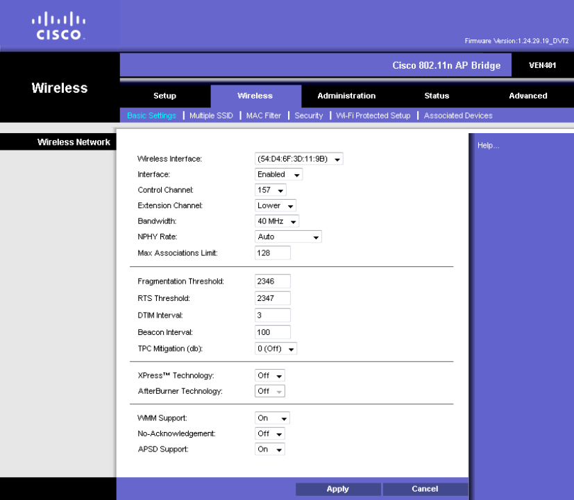
Basic Wireless Settings
Use the Basic Settings screen to the wireless interface for your device.
1 If you are configuring a VEN402 client device, you may enter the Network Name
(SSID) for the wireless network you want to join in the field provided.
Otherwise, go to step 2.
2 From the Wireless Network Wireless Interface field, select which wireless
interface you want to configure.
3 Do you have any Wireless-N (5GHz) devices in your network?
If yes, select Enabled for the Interface field to run wireless on your network.
If no, select Disabled.
DRAFT
Chapter 2 Web-Based User Interface
12 4038769 Rev 01
4 Your device selects the optimum Control Channel for Wireless-N(5GHz)
networking by default. If you want to configure the Control Channel manually,
select another setting form the drop-down menu.
5 Use the following guidelines to configure the remaining fields:
Note: This list below varies based on the code version on your device. If you
have a question about any field, please contact your service provider.
Extension Channel: If you selected 40MHz Channel for the Bandwidth
setting, then this setting will be available for your primary Wireless-N
(5GHz) channel. If you are not sure which channel to select, keep the default
setting of Upper/Lower.
Bandwidth: You can select the channel bandwidth manually for Wireless-N
connections. When it is set to 20MHz, only the 20MHz channel is used. When
it is set to 40MHz, Wireless-N connections will use the 40MHz channel.
Max Associations Limit: Enter the maximum number of wireless clients that
can be connected at a time. The acceptable range is 1 through 128.
Fragmentation Threshold: Enter a the maximum packet byte size to allow.
Packets that exceed this value will be subdivided. This value specifies the
maximum size for a packet before data is fragmented into multiple packets. If
you experience a high packet error rate, you may slightly increase the
Fragmentation Threshold. Setting the Fragmentation Threshold too low may
result in poor network performance. Only minor reduction of the default
value is recommended. In most cases, it should remain at its default value of
2346.The acceptable range is 256 through 2346.
RTS Threshold: Enter the maximum bytes allowed for the Request to Send
(RTS) Threshold to define how often RTS packets will be sent. Should you
encounter inconsistent data flow, only minor reduction of the default, 2346, is
recommended. If a network packet is smaller than the preset RTS threshold
size, the RTS/CTS mechanism will not be enabled. The device sends Request
to Send (RTS) frames to a particular receiving station and negotiates the
sending of a data frame. After receiving an RTS, the wireless station responds
with a Clear to Send (CTS) frame to acknowledge the right to begin
transmission. The RTS Threshold value should remain at its default value of
2346.The acceptable range is 256 through 2346.
DTIM Interval: Enter a value between 1 and 255 to set the interval of the
Delivery Traffic Indication Message (DTIM). A DTIM field is a countdown
field informing clients of the next window for listening to broadcast and
multicast messages. When the device has buffered broadcast or multicast
messages for associated clients, it sends the next DTIM with a DTIM Interval
value. Its clients hear the beacons and awaken to receive the broadcast and
multicast messages. The default value is 1.
Beacon Interval: Enter a value between 1 and 65,535 milliseconds to set the
frequency of the beacon interval for the device. A beacon is a packet
broadcast by the device to synchronize the wireless network(s). The default
value is 100.
DRAFT
Wireless Setup
4038769 Rev 01 13
TPC Mitigation (db): Power Mitigation factor (in db).
WMM Support: The device supports Wi-Fi Multimedia (WMM) for Quality
of Service (QoS). When WMM Support is enabled, it provides four priority
queues for different types of traffic. It automatically maps the incoming
packets to the appropriate queues based on QoS settings (in the IP or layer 2
header). WMM provides the capability to prioritize traffic in your
environment. If you have other devices on your network that support WMM,
select On. The default is On.
No-Acknowledgement: When enabled, wireless devices will not
acknowledge each transmitted packet. This may cause more efficient
throughput in low RF noise environments, but will degrade performance in
noisy environments. The default is Off.
APSD Support: Automatic Power Save Delivery (APSD) is a special power-
saving mode to achieve end-to-end QoS. This option is available if you
enabled WMM Support. Select On to enable Automatic Power Save Delivery
(APSD) or Off to disable this feature.
6 Click the Apply button to apply your changes or Cancel button to cancel.
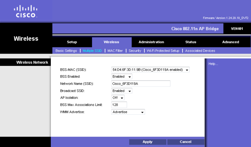
Multiple SSID Settings
The Multiple SSID Settings screen allows you to manage your wireless network if
your Access Point will be used to support multiple stations.
Note: The mutiple SSID parameters are applicable only to the VEN401 Access Point
device. The VEN402 client device does not support multiple SSIDs.
DRAFT
Chapter 2 Web-Based User Interface
14 4038769 Rev 01
1 From the BSS-MAC(SSID) field, select the wireless BSSID interface you want to
configure.
2 Do you want to enable this interface?
a If yes, select Enabled for the BSS-Enabled field and continue with step 3.
b If no, select Disabled and skip to the last step.
3 For added security, you should change the default SSID (Cisco) in the Network
Name (SSID) field to a unique name.
Note: The SSID is the network name shared among all points in a wireless
network. The SSID must be identical for all devices in the wireless network. It is
case-sensitive and must not exceed 32 characters (use any of the characters on the
keyboard). Make sure this setting is the same for all points in your wireless
network.
4 When wireless clients survey the local area for wireless networks to associate
with, they will detect the SSID broadcast by the Access Point. Do you want to
broadcast the Access Point’s SSID?
If yes, keep the default setting, Enabled, for the Broadcast SSID field.
If no, then select Disabled.
5 Do you want to prevent stations (STAs) associated with your Access Point from
communicating with each other?
If yes, select On for the AP Isolation field.
If no, select Off.
6 Enter a value in the BSS Max Associations Limit field to set the number of
associations the device can accept.
7 Do you want to allow WMM to be advertised in beacons and probes for this
interface?
If yes, select Advertise for the WMM Advertise field.
If no, select Do Not Advertise.
8 Click the Apply button to apply your changes or the Cancel button to cancel.
DRAFT
Wireless Setup
4038769 Rev 01 15
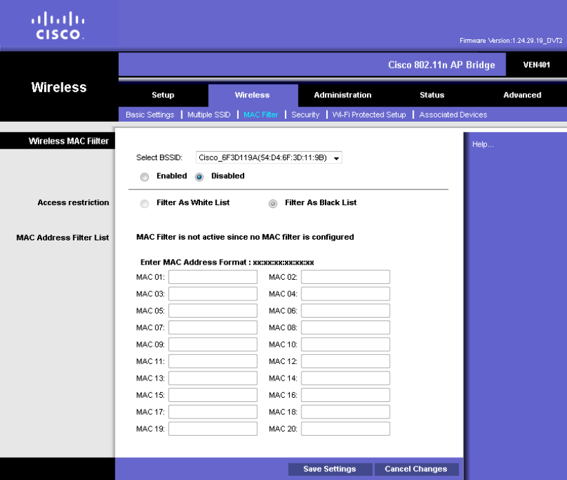
MAC Filter Settings
Wireless access can be filtered by using the MAC addresses of the wireless devices
transmitting within your network.
1 From the Select BSSID field, select the device you want to configure.
2 Do you want to use the Wireless MAC Filter feature for the device selected?
a If yes, select Enabled and continue with step 3.
b If no, select Disabled and skip to the last step.
3 Select the Access Restriction method you want to use as follows:
Filter As White List - Select this option to allow only PCs whose MAC
addresses are listed on this screen access to the wireless network.
Filter As Black List - Select this option to block the PCs whose MAC
addresses are listed on this screen from accessing the wireless network.
4 Enter the MAC Addresses whose wireless access you want to control in the fields
provided.
DRAFT
Chapter 2 Web-Based User Interface
16 4038769 Rev 01
5 Click the Save Settings button to apply your changes or Cancel Changes button
to cancel.
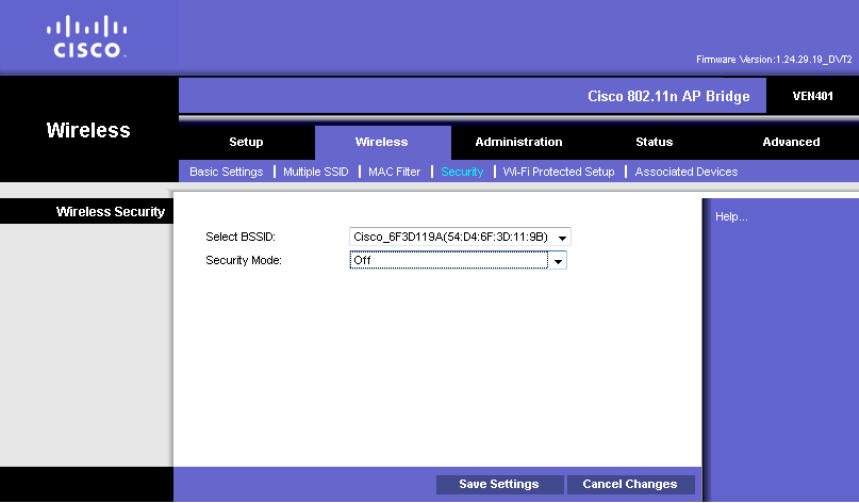
Security Settings
Use this screen to configure the security of your wireless network.
Complete the following steps to select a security mode for a specific BSSID.
1 Are you configuring a VEN401 or VEN402 device?
If you are configuring a VEN401, select the wireless BSSID interface you wish
to configure from the Select BSSID drop-down menu.
If you are configuring a VEN402, the Network Name (SSID) field appears in
a non-editable field.
2 Select the Security Mode setting desired per the guidelines below:
Off—This option turns the security feature off. Off: This option features no
security on your wireless network. If you select this option, skip to the last
step.
Note: Some countries require by law for wireless networks to be secured.
Cisco is not responsible for users who do not adhere to country-specific
regulations. Contact your service provider to find out what your country
requires.
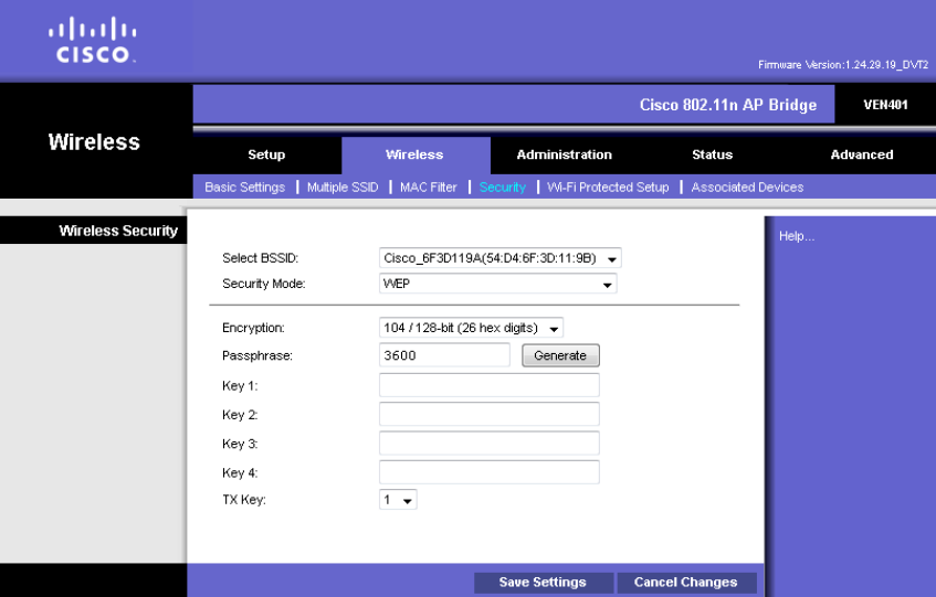
WEP—WEP is a basic encryption method, which is not as secure as the other
methods available.
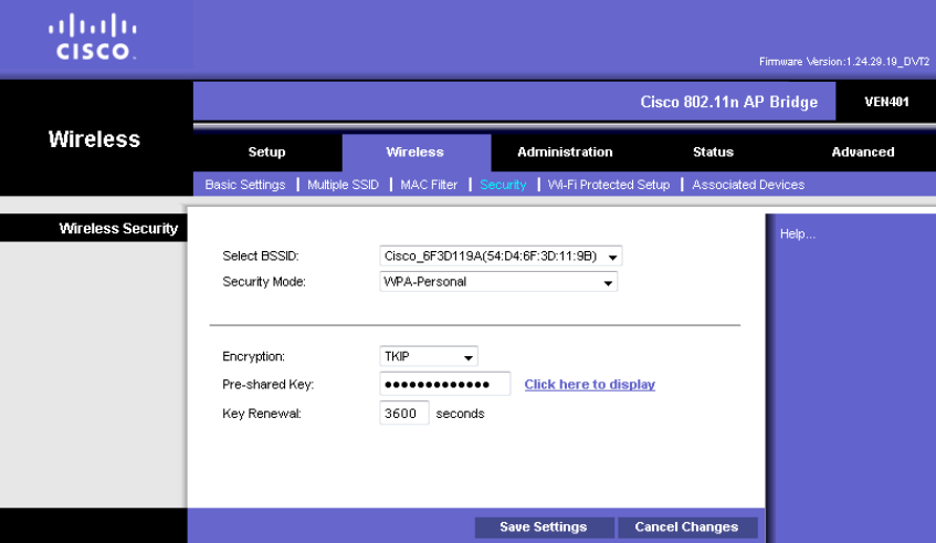
WPA-Personal—This method offers three encryption methods, TKIP, AES,
and TKIP or AES, with dynamic encryption keys.
DRAFT
Wireless Setup
4038769 Rev 01 17
WPA2-Personal—WPA2-Personal is a stronger encryption method than
WPA-Personal. This method offers three encryption methods, TKIP, AES,
and TKIP or AES, with dynamic encryption keys.
Mixed WPA2 Personal/WPA Personal—This options supports both WPA
and WPA2 clients.
3 Did you select WEP?
If yes, continue with the WEP Settings (on page 17) section to complete your
security setup.
If no, continue with the Other Security Mode Settings (on page 18) section to
complete your security setup.
4 Click the Save Settings button to apply your changes or Cancel Changes button
to cancel.
WEP Settings
Complete the following steps if you select WEP for the Security Mode.
1 Select a level of WEP encryption, 40/64-bit (10 hex digits) or 104/128-bit (26 hex
digits).
2 If you want to use a Passphrase to automatically generate WEP keys?
If yes, enter the Passphrase in the field field and click the Generate button.
Skip to the last step.
Note: The WEP Passphrase is compatible with Cisco wireless products only.
If you are using non-Cisco products, manually enter the appropriate WEP
key on those devices.
DRAFT
Chapter 2 Web-Based User Interface
18 4038769 Rev 01
If no, leave the Passphrase field empty and continue with step 3.
3 Enter the WEP key(s) manually in the fields provided (Key 1-4).
4 To indicate which WEP key to use, select the appropriate Transmit (TX) Key
number from the drop-down menu.
5 Click the Save Settings button to apply your changes or Cancel Changes button
to cancel.
Other Security Mode Settings
Complete the following steps if you select WPA-Personal, WPA2-Personal, or
Mixed WPA2 Personal/WPA Personal for the Security Mode.
1 Select the type of encryption method you want to use, TKIP, AES, or TKIP or
AES.
2 Enter the Pre-shared Key (also known as a Passphrase), which can have 8 to 63
characters.
Note: The Click here to display link opens a text file with the key in clear text.
3 Enter the Key Renewal period, which configures how often the Router changes
the encryption keys.
4 Click the Save Settings button to apply your changes or Cancel Changes button
to cancel.
DRAFT
Wireless Setup
4038769 Rev 01 19
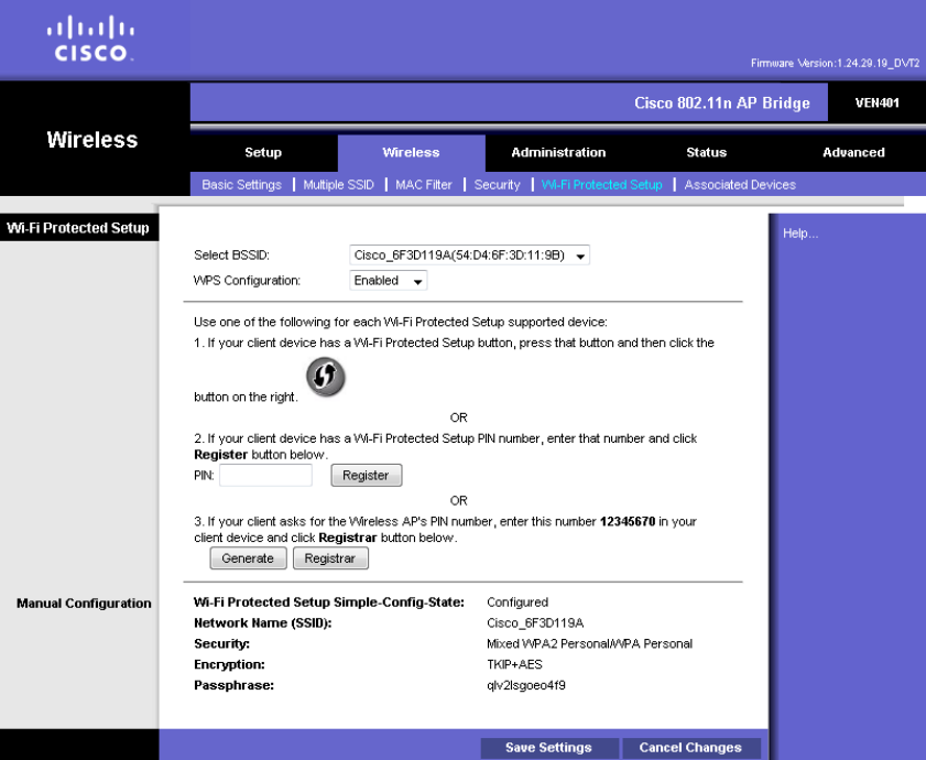
Wi-Fi Protected Setup
Set Up WPS on the VEN401
Use this screen to enable the Wi-Fi Protected Setup (WPS) feature on your VEN401
Access Point device.
1 From the Select BSSID drop-down menu select the wireless BSSID interface you
want to configure.
2 From the WPS Configuration drop-down menu select Enabled to enable the
WPS feature.
3 If your client device has a WPS button, complete the steps below to pair your
devices. Otherwise, skip to step 4.
a Click or press the WPS button on the client device.
b Click the WPS button on this screen.
c After the client devices have been paired, click the OK button.
d Skip to step 5.
DRAFT
Chapter 2 Web-Based User Interface
20 4038769 Rev 01
4 If your client device has a WPS PIN or passcode, complete the steps below:
a Enter your PIN in the field provided.
b Click the Register button.
c After the client devices has been configured, click the OK button.
5 Click the Save Settings button to apply your changes or Cancel Changes button
to cancel.
6 Refer back to your client device or its documentation for further instructions.
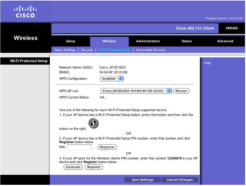
Set Up WPS on the VEN402
Use this screen to use the Wi-Fi Protected Setup (WPS) feature on the VEN402 client
device. The Network Name (SSID) and BSSID are identified in non-editable fields.
1 From the WPS Configuration menu select Enabled to enable the WPS feature.
2 From the WPS AP List menu, select the desired access point from the list of
available options. If necessary, click the Rescan button to refresh the list. The
WPS Current Status field indicates that the scan is in process or complete.
3 If your access point device has a WPS button, complete the steps below to pair
your devices. Otherwise, skip to step 4.
a Click or press the WPS button on the client device.
b Click the WPS button on this screen.
c After the client devices have been paired, click the OK button.
DRAFT
Wireless Setup
4038769 Rev 01 21
d Skip to the last step.
4 If your client device has a WPS PIN or passcode, complete the steps below:
a Enter your PIN in the field provided.
b Click the Register button.
c After the client devices has been configured, click the OK button.
5 Click the Save Settings button to apply your changes or Cancel Changes button
to cancel.
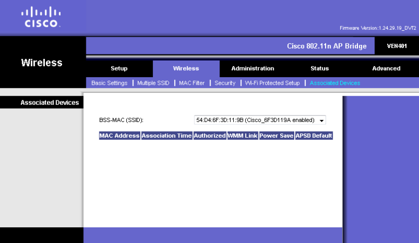
Associated Devices
Use this screen to list the devices associated with a specific SSID.
To view details for an associated device, select the SSID from the drop-down menu.
The page refreshes with a list of devices associated with the selected SSID and
general information for each device found.
DRAFT
Chapter 2 Web-Based User Interface
22 4038769 Rev 01
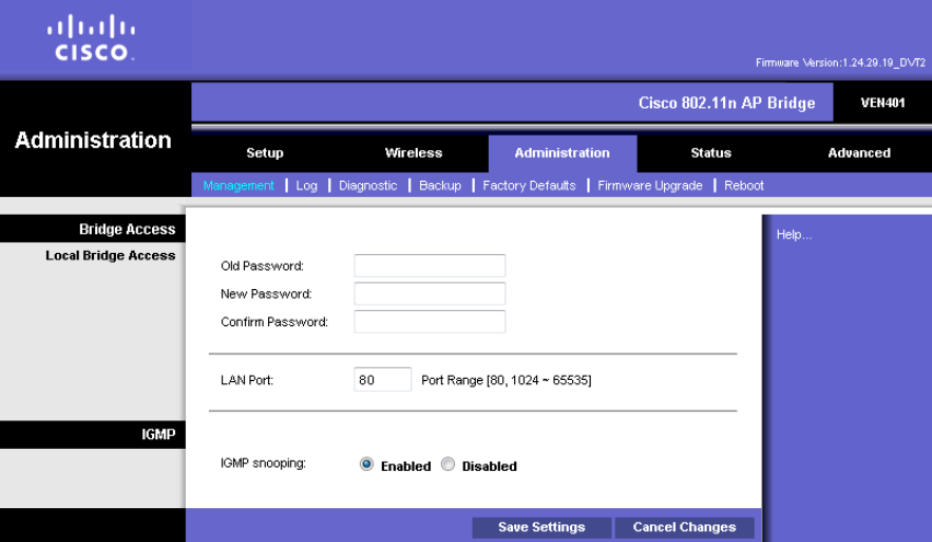
Administration Setup
Management Settings
Use this screen setup or change your password, LAN Port, or IGMP setting.
Password
Complete the following steps to setup or change the password you are prompted to
provide when you access the web-based utility.
Note: The default password is admin.
1 Enter the current password in the Old Password field.
2 Enter the new password in the New Password field.
3 Re-enter the new password in the Confirm Password field.
4 Click the Save Settings button to apply your changes or Cancel Changes button
to cancel.
LAN Port
Enter the desired TCP port for the device’s web-based utility in the LAN Port field.
Click the Save Settings button to apply your changes or Cancel Changes button to
cancel.
DRAFT
Administration Setup
4038769 Rev 01 23
IGMP
The Internet Group Membership Protocol (IGMP ) feature improves multicasting for
LAN-side clients. Select Enabled if your clients support IGMP, otherwise, select
Disabled. Click the Save Settings button to apply your changes or Cancel Changes
button to cancel.
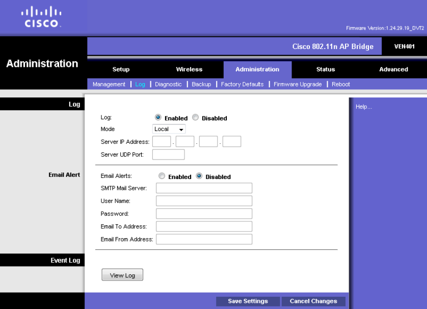
Log Settings
Use this screen to configure the device to record system activity in a log or to view
the log report.
Configure Log Settings
Complete the following steps to enable or disable log reporting.
1 Do you wish to enable log reporting?
If yes, select the Enabled radio button for the Log field and continue with
step 2.
If no, select the Disabled radio button for the Log field and skip to the last
step.
DRAFT
Chapter 2 Web-Based User Interface
24 4038769 Rev 01
2 Select one of the following options from the Mode drop-down menu:
Local—Select this option to retrieve logs from the local server. When this
option is selected, the Server IP and Server UDP Port fields are not
applicable.
Remote—Select this option to send logs to a system server. When this option
is selected, the Server IP and Server UDP Port fields are required.
3 Enter the Server IP Address of your syslog server.
4 Enter the Server UDP Port of your syslog server.
5 Do you wish to receive email alerts if a log message is detected?
If yes, select the Enabled radio button for the Email Alerts field and complete
the following fields:
– SMTP Mail Server—Enter the address (domain name) or IP address of
the SMTP (Simple Mail Transport Protocol) Server you use for outgoing
E-mail.
– Email To Address—Enter the E-mail address the alert is to be sent to.
– Email From Address—Enter the E-mail will show this address as the
Sender's address.
If no, select the Disabled radio button for the Email Alerts field and skip to
the last step.
6 Click the Save Settings button to apply your changes or Cancel Changes button
to cancel.
View Log
Complete the following steps to view the logs.
1 Click the View Log button. A new window appears with the log data.
2 Click the Refresh button to update the log.
3 Click the Clear button to clear all the information in the current log.
4 Click the Close button to close window.
DRAFT
Administration Setup
4038769 Rev 01 25
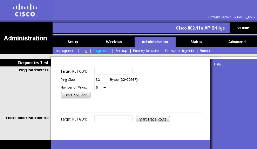
Diagnostics
Use this screen to execute a ping test or trace route request. The ping test allows you
to check the connections of your network devices, including connection to the
Internet.
Ping Test
Complete the following steps to execute a ping test.
1 Enter the IP address or Fully Qualified Domain Name (FQDN) that you want to
ping in the Target IP/FQDN field. This can be either a local (LAN) or Internet
(WAN) IP address.
2 Enter the packet size you want to use in the Ping Size field. The default is 32
bytes.
3 Enter how many times you want to ping in the Number of Pings field. The
default is 3.
4 Enter the number of milliseconds before the ping test will time out in the Ping
Timeout field. The default is 5000 milliseconds.
5 Click the Start Test button. The results of the ping test are displayed.
6 Click Refresh to update the on-screen information.
DRAFT
Chapter 2 Web-Based User Interface
26 4038769 Rev 01
Trace Route Parameters
Complete the following steps to execute a trace route request.
1 Enter the desired IP address or Fully Qualified Domain Name (FQDN) in the
Target IP/FQDN field. This can be either a local (LAN) or Internet (WAN) IP
address.
2 Click the Start Trace Route button. The results are displayed.
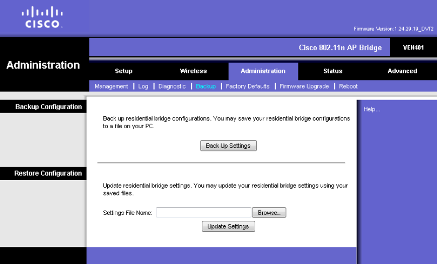
Backup Settings
The Backup screen allows you to back up or restore the device’s settings using a
configuration file.
Path: Administration > Backup
Backup Configuration
Back Up Settings—To save the device's settings in a configuration file, click this
button and follow the on-screen instructions.
Restore Configuration
To use this option, you must have previously backed up its configuration settings.
Settings File Name—Click Browse and select the device’s configuration file.
Update Settings—To restore the device’s configuration settings, click this button
and follow the on-screen instructions.
DRAFT
Administration Setup
4038769 Rev 01 27
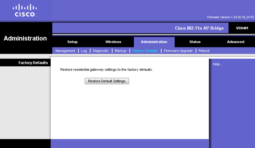
Factory Default Settings
The Factory Defaults screen allows you to restore the device’s configuration to its
factory default settings. (An alternative method is to press and hold the Reset button
on the back panel of your device for approximately ten seconds.)
Path: Administration > Factory Defaults
Restore Default Settings—Click this button to restore settings to the factory default
values. You will be prompted to confirm or cancel the restore request.
Note: Restoring factory defaults on the device deletes custom settings. Record your
custom settings before clicking the Restore Factory Defaults button.
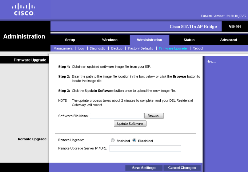
Firmware Upgrade
The Firmware Upgrade screen allows you to upgrade the firmware. Do not upgrade
the firmware unless you are experiencing problems with the device or the new
firmware has a feature you want to use.
Note: When up upgrade, the device may lose the settings you have customized.
Before you upgrade its firmware, write down all of your custom settings. After you
upgrade its firmware, you will have to re-enter all of your configuration settings.
DRAFT
Chapter 2 Web-Based User Interface
28 4038769 Rev 01
Path: Administration > Upgrade
Upgrade Firmware
Follow the on-screen instructions to upgrade the firmware manually.
Software File Name—Click the Browse button and select the firmware upgrade file.
Update Software—After you have selected the appropriate file, click this button,
and follow the on-screen instructions.
DRAFT
Administration Setup
4038769 Rev 01 29
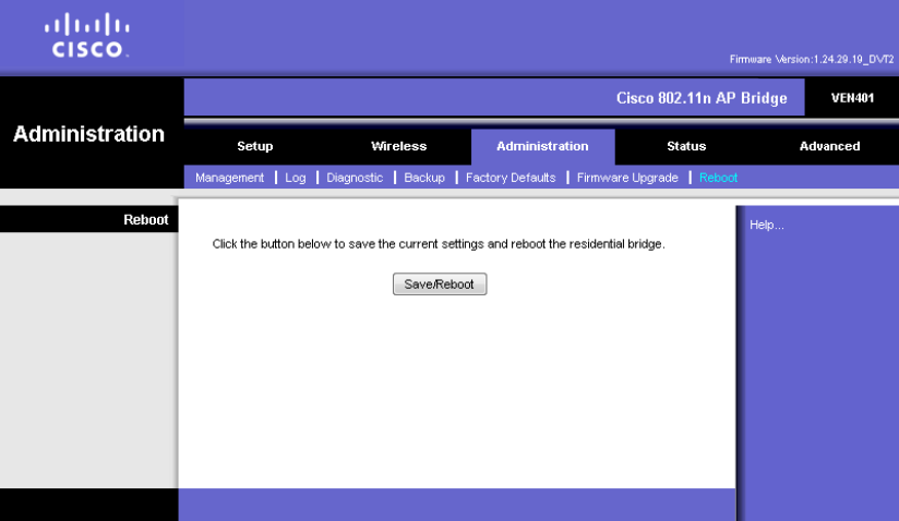
Reboot
The Reboot screen allows you to gracefully stop and restart the device. Performing a
reboot allows you to save any configuration changes and to reboot the device to
make the changes take effect.
Path: Administration > Reboot
Click Save/Reboot to reboot the device. The restart will terminate the Internet
connection.
DRAFT
Status Information
30 4038769 Rev 01
Status Information
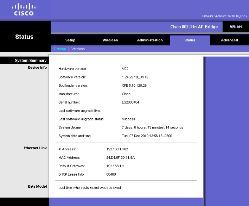
General System Status Information
Use this screen to view general information for your device.
Device Information
Hardware Version—Provides the version number of the device’s hardware.
Software Version—Provides the version number of the device's software.
Bootloader version—Provides the version number of the bootloader.
Manufacturer—Provides the manufacturer name.
Serial Number—Provides the serial number of the device.
Last software upgrade time—Indicates most recent upgrade attempt.
Last software upgrade status—Indicates if upgrade attempt succeeded or failed.
DRAFT
Status Information
4038769 Rev 01 31
System Uptime—Provides the length of time the device has been active.
System date and time—Provides the current date and time of the device.
Ethernet Link
IP Address—Provides the device's IP address, as it appears on your local network.
MAC Address—Provides the device’s MAC address.
Default Gateway—Provides the default gateway IP address.
DHCP Lease Time—Provides the length of time for the DHCP lease setting.
Data Model
Provides date and time of the most current update to the data model.
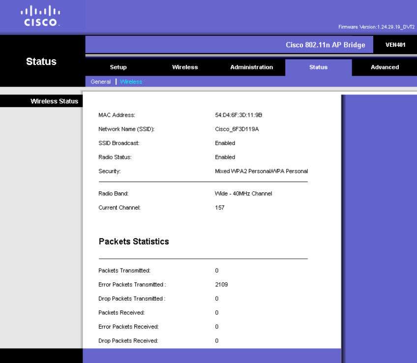
Wireless Status Information
Use this screen to view the status of your wireless connection.
MAC Address—Provides the MAC address of the device’s local, wireless interface.
DRAFT
Status Information
32 4038769 Rev 01
Network Name (SSID)—Provides the name of the wireless network.
SSID Broadcast—Indicates if the SSID broadcast setting is enabled or disabled.
Radio Status—Indicates if the radio is enable or disabled.
Security—Provides the wireless security method.
Radio Band—Provides the radio band setting.
Current Channel-Provides the channel associated with the frequency that the radio
band uses.
Packet Statistics
This section lists the number of packets transmitted and received, including attempts
that encounter an error condition or are dropped.
DRAFT
4038769 Rev 01 33
DRAFT

Cisco Systems, Inc.
5030 Sugarloaf Parkway, Box 465447
Lawrenceville, GA 30042
678 277-1120
800 722-2009
www.cisco.com
This document includes various trademarks of Cisco Systems, Inc. Please see the Notices
section of this document for a list of the Cisco Systems, Inc. trademarks used in this
document.
Product and service availability are subject to change without notice.
© 2011 Cisco and/or its affiliates. All rights reserved.
February 2011
Part Number 4038769 Rev 01
DRAFT