GemTek Technology CISCO867VAE XDSL Router User Manual HIG880 860
Gemtek Technology Co., Ltd. XDSL Router HIG880 860
UserManual.wiki
>
GemTek Technology
>
CISCO867VAE User Manual
>
User Manual Part 1
Contents
1.
User Manual Part 1
2.
User Manual Part 2
3.
User Manual Statements Part 1
4.
User Manual Statements Part 2
User Manual Part 1
Navigation menu
Upload a User Manual
Namespaces
Wiki Guide
HTML
PDF
Info
Views
User Manual
Discussion / Help
Navigation
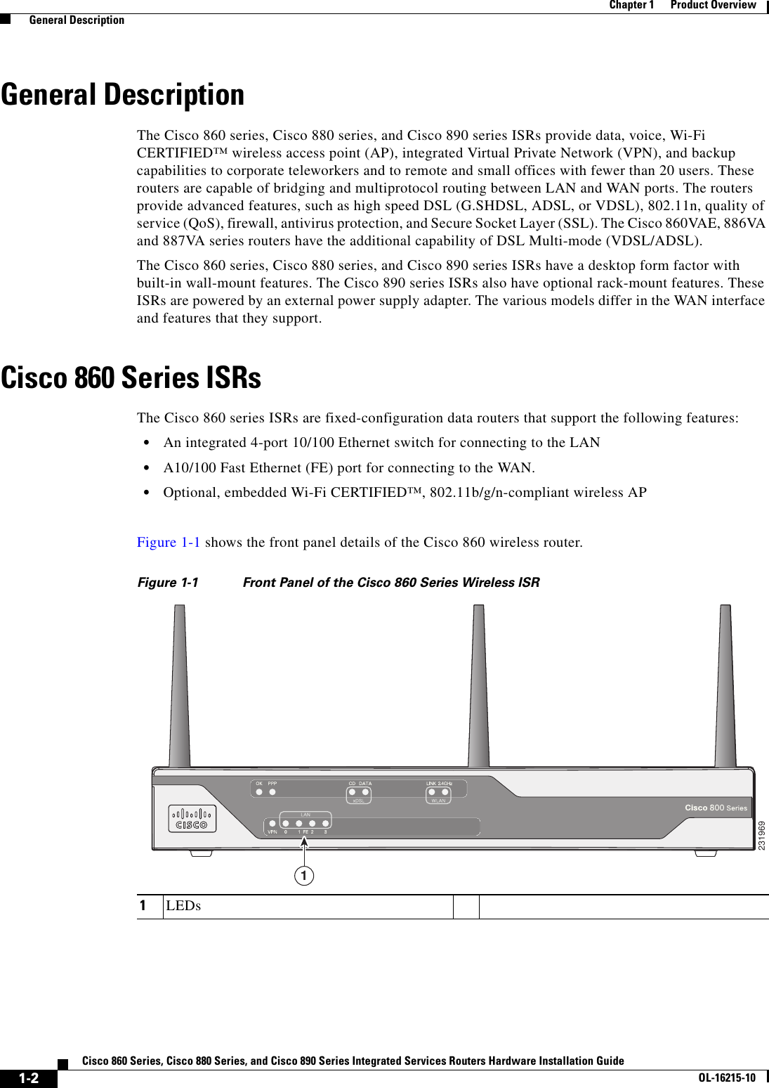
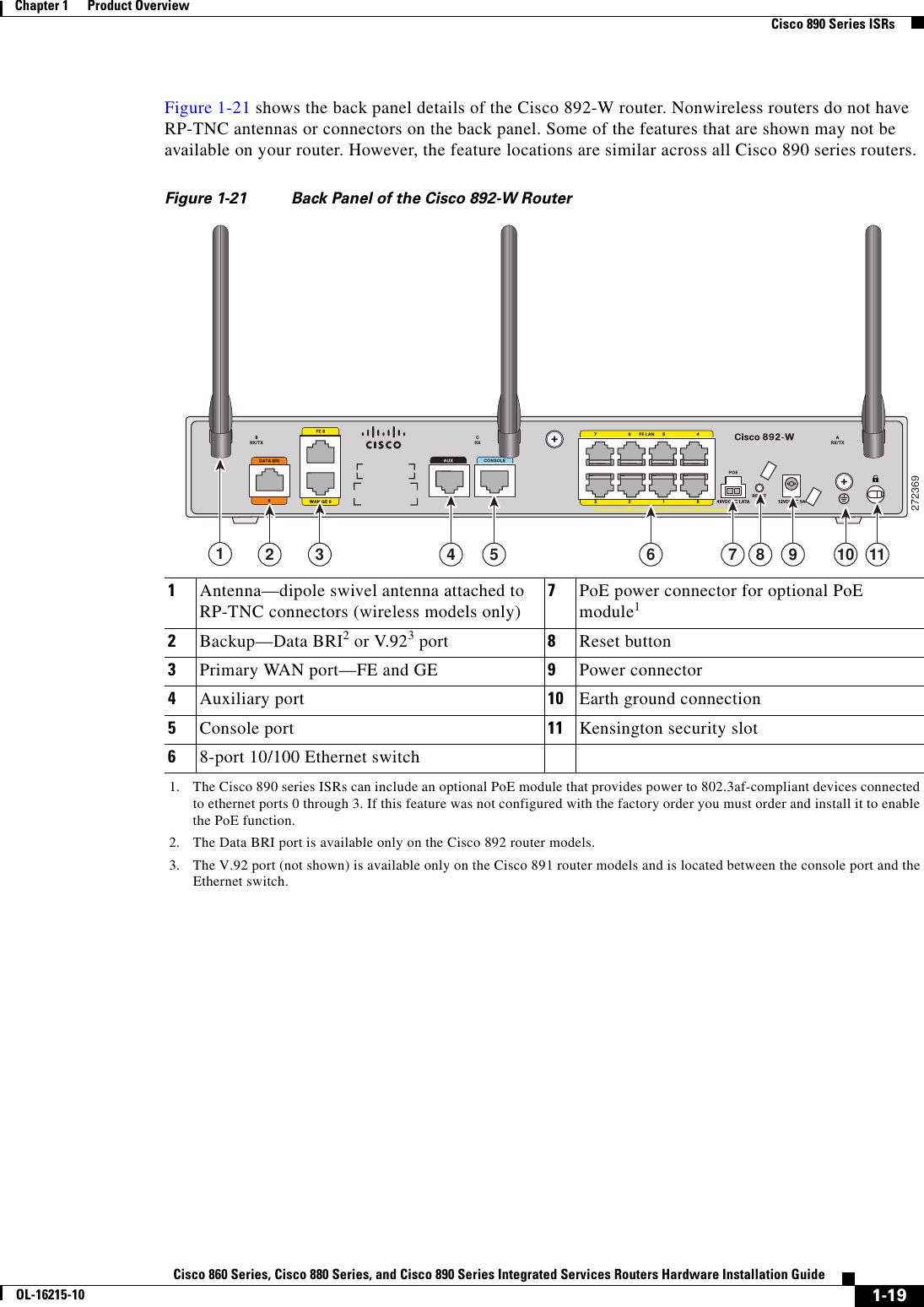
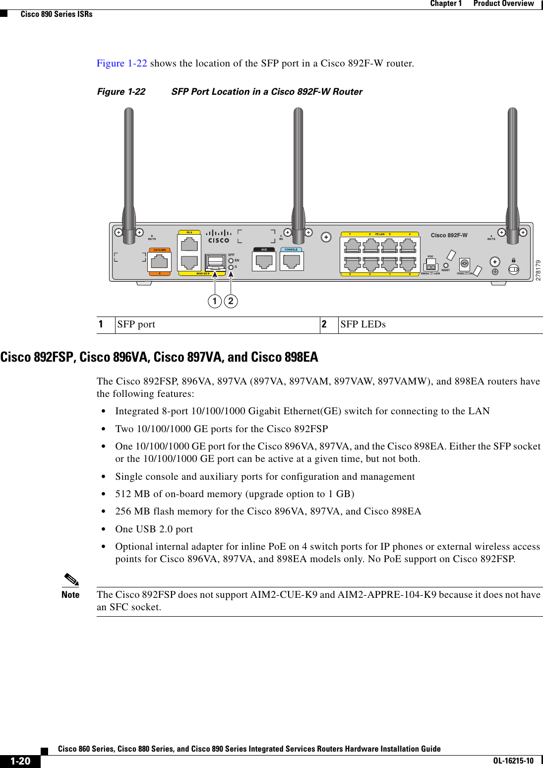
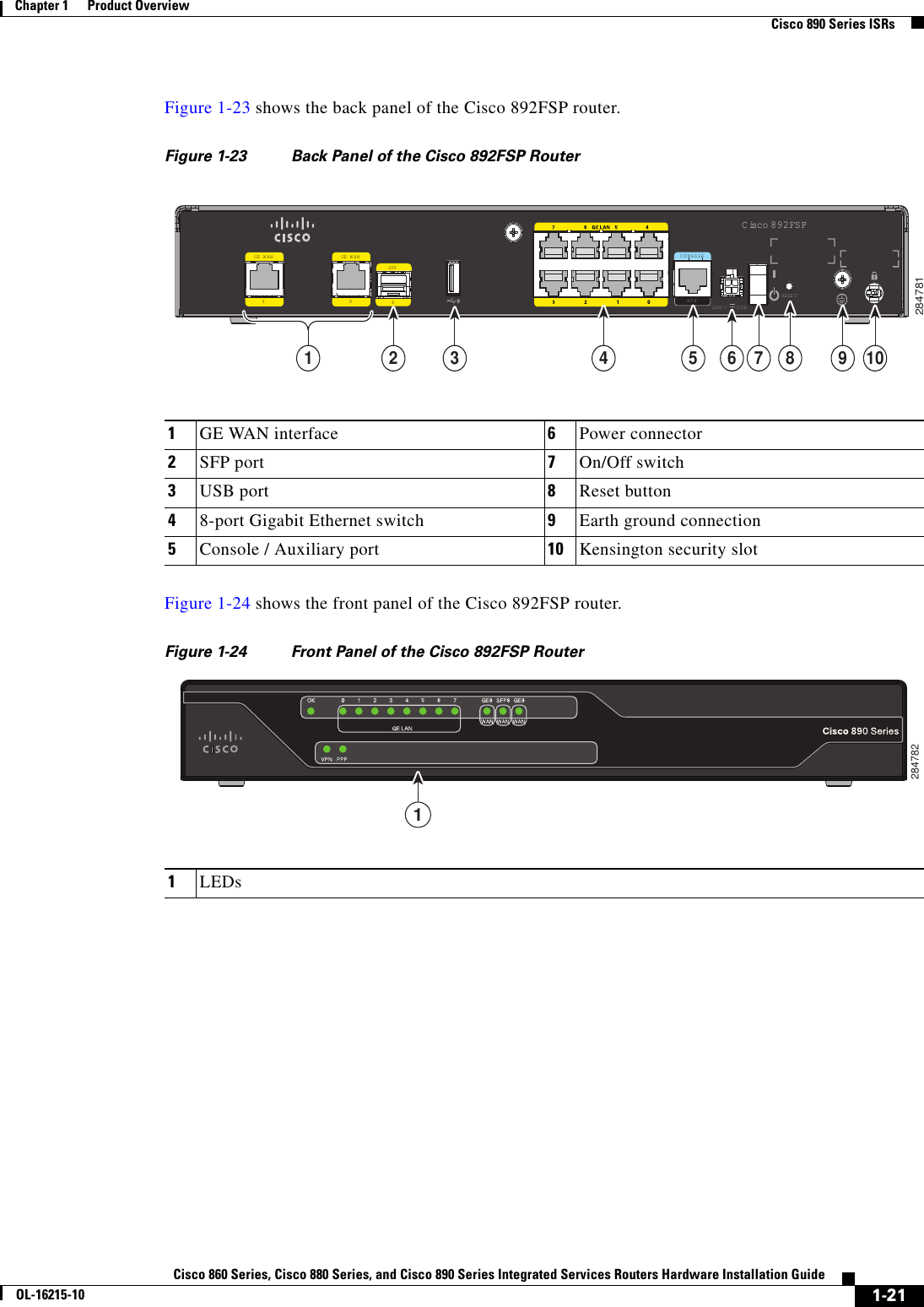
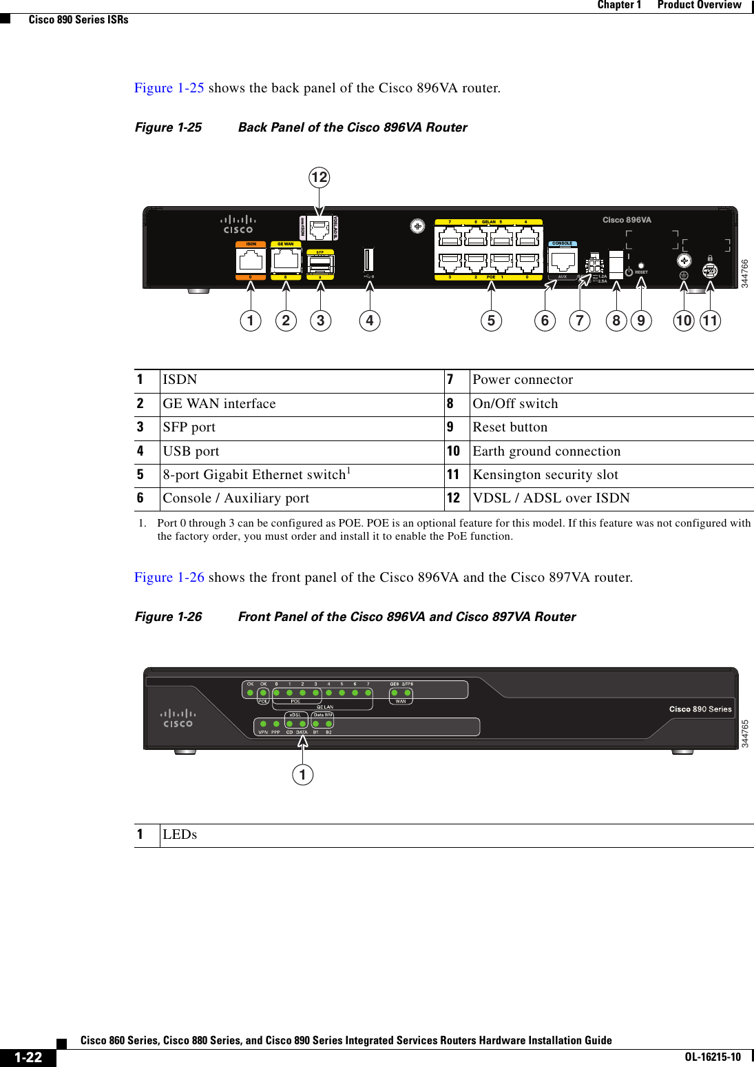
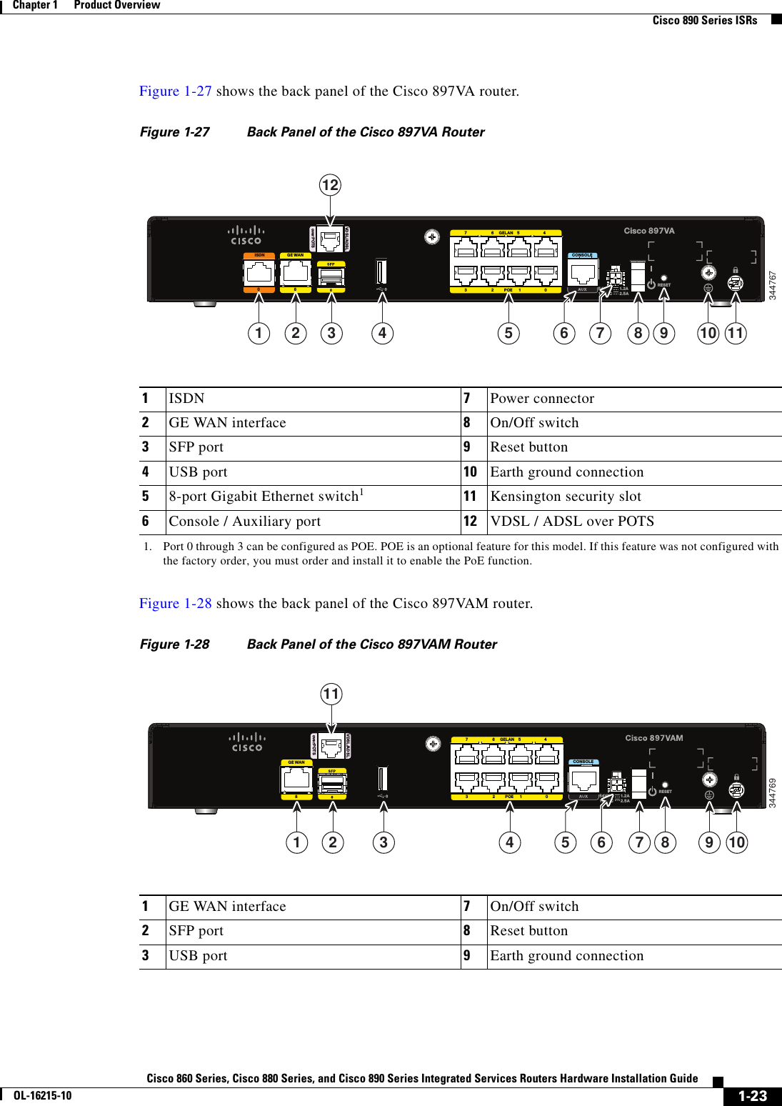
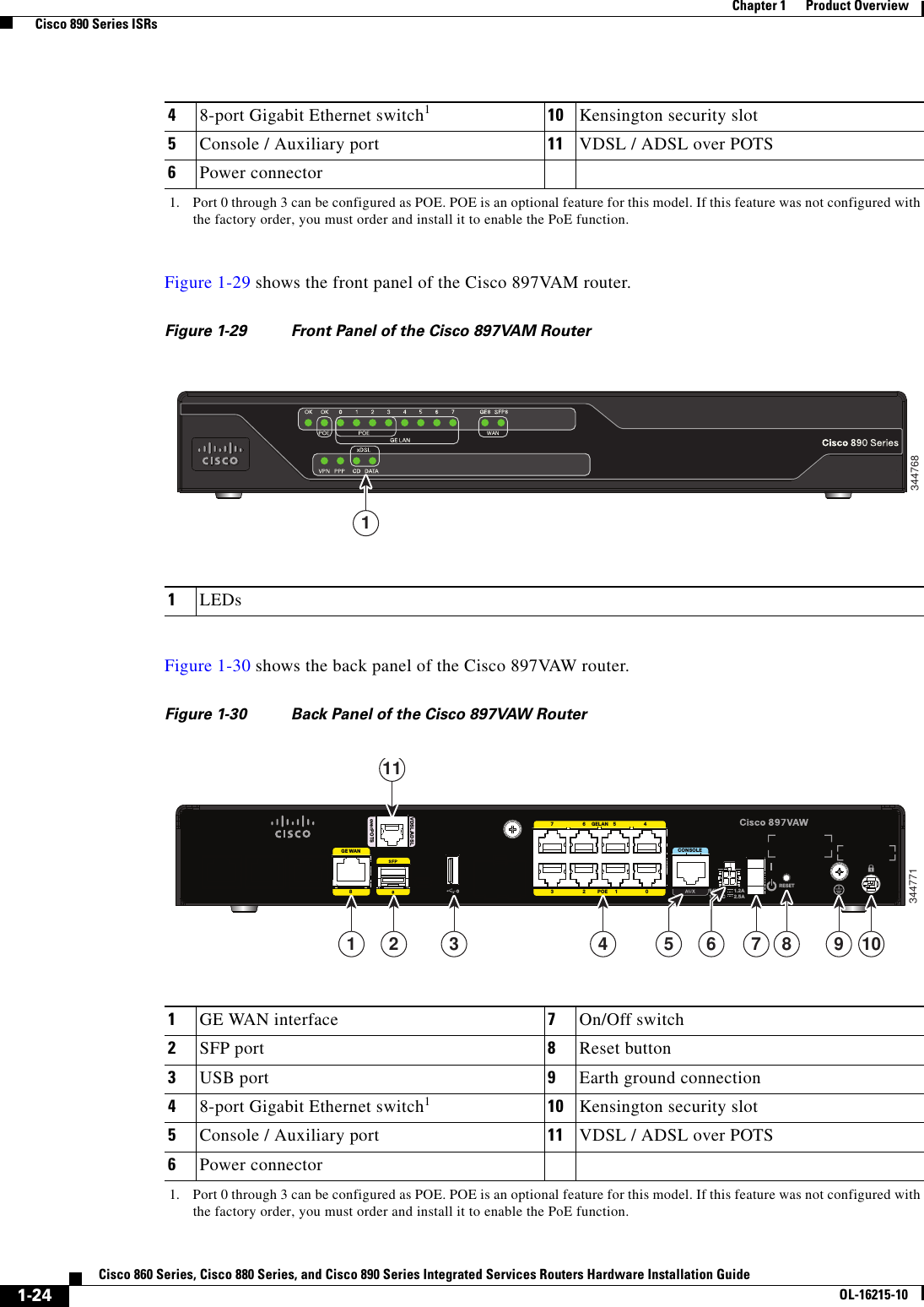
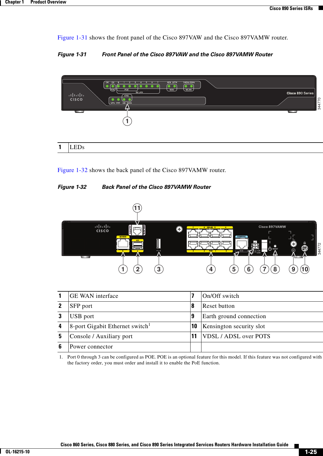

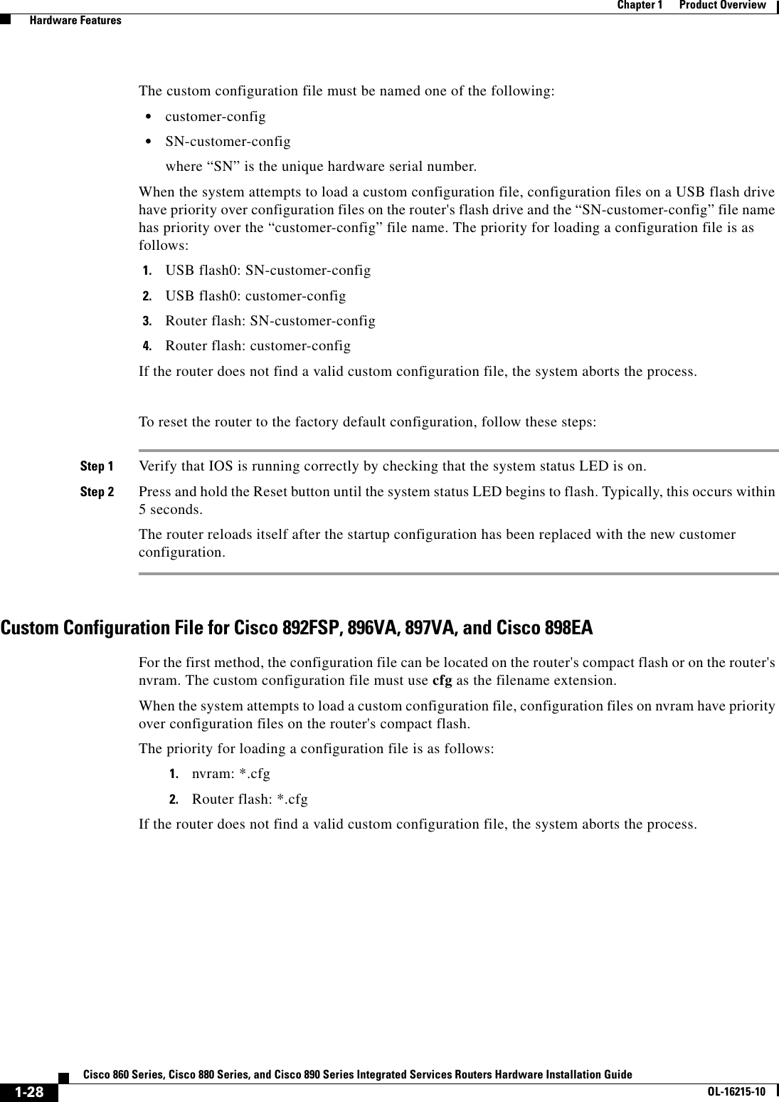
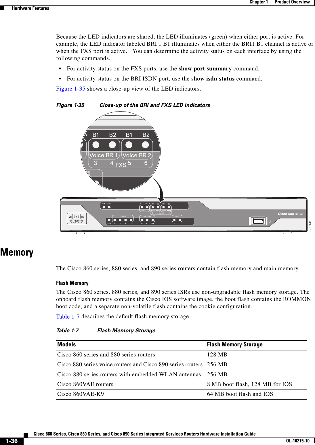
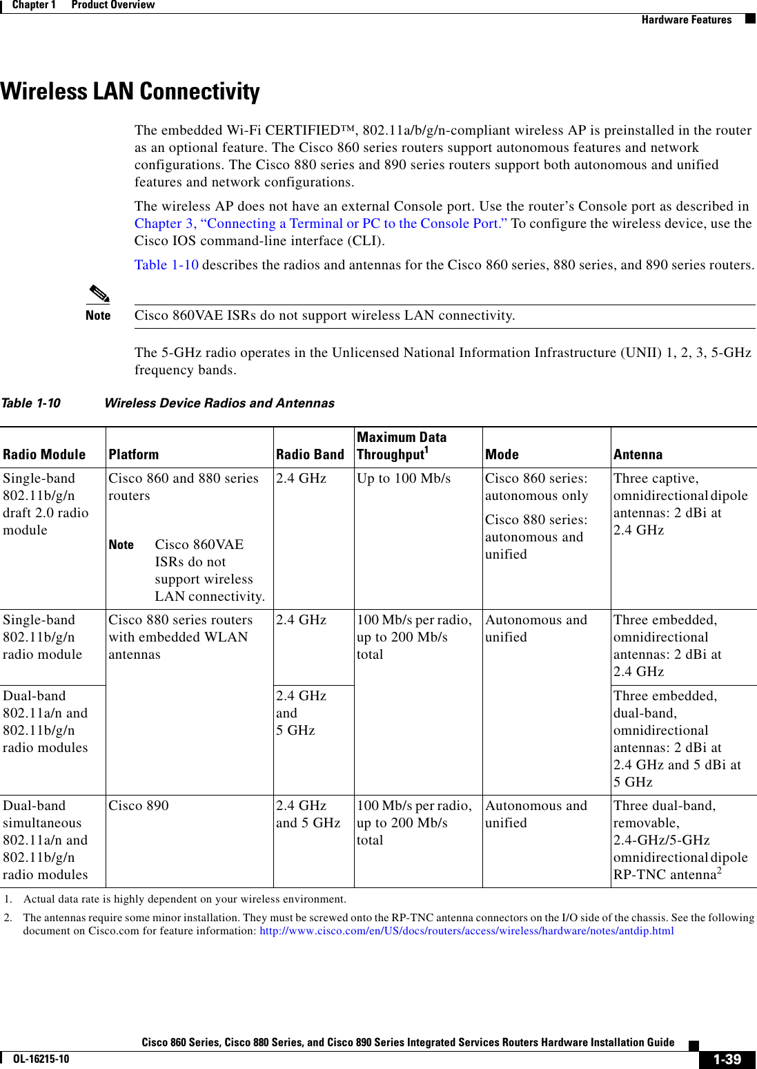
![1-38Cisco 860 Series, Cisco 880 Series, and Cisco 890 Series Integrated Services Routers Hardware Installation GuideOL-16215-10Chapter 1 Product Overview Hardware FeaturesThe following models have no fan: • Cisco 892FSP • Cisco 896VA • Cisco 897VA • Cisco 898EAPower Supply The Cisco 892FSP has a single +12V power supply input. The Cisco 892FSP power connector is different from the barrel-type connector on other 890 series models. The AC adapter cable connector has four pins and a built-in locking mechanism. Figure 3-27 shows the power adapter connector. The Cisco 896VA, 897VA, and Cisco 898EA use PoE (12 VDC 43 W, -54 VDC 80 W) and non-PoE (12 VDC 60 W) power supplies.Power over Ethernet Module The Cisco 880 series ISRs can include an optional Power over Ethernet (PoE) module that provides power to 802.3af-compliant devices connected to FE ports 0 and 1. The Cisco 890 series ISRs can include an optional PoE module that provides power to 802.3af-compliant devices connected to FE ports 0, 1, 2, and 3.The PoE module is an option available only for the Cisco 880 series and 890 series ISRs and requires a 48 V external power adapter.This function can be added to an 880 or 890 series router by installing the PoE adapter card in the router and inserting the PoE 48 V external power adapter.Note The Cisco 880 series ISRs with embedded WLAN antennas require a single external power supply: a 30 W power supply for non-POE-enabled routers or a 60 W power supply for POE-enabled routers. For the back panels of some of these routers, see Figure 1-17 and Figure 1-19.3G Cellular Data WAN ConnectivityThe 3G (Evolution Data Only [EVDO], Universal Mobile Telecommunications Systems [UMTS]) cellular interface is intended for use as a backup data link, but it can also be used as a primary WAN data link. The 3G technology is third-generation wide-area cellular technology that is used in voice telephony and broadband wireless data in a mobile environment. Some Cisco 880G models come with a 34-mm express card slot ready for use with a commercial 3G card radio. The 3G express card slot is located on the front panel. For a list of supported 3G cards, see the Cisco 880 Series Integrated Services Routers Data Sheet.Other Cisco 880G models come with embedded WAN modems for use over GSM or CDMA networks. These routers have antenna connectors on the back panel. GSM routers have two SIM card slots. For information on configuring Cisco 880 series ISRs for 3G, see Configuring Cisco EHWIC and 880G for 3G (EV-DO Rev A) and Configuring Cisco EHWIC and 880G for 3.7G (HSPA+)/3.5G (HSPA).](https://usermanual.wiki/GemTek-Technology/CISCO867VAE.User-Manual-Part-1/User-Guide-1959035-Page-54.png)