General Dynamics Broand NODEBHZ1 Wireless Broadband Base Station User Manual NodeB V2 Installation Guide
General Dynamics Broadband, Inc. Wireless Broadband Base Station NodeB V2 Installation Guide
Contents
- 1. Installation Guide 1
- 2. Installation Guide 2
- 3. Installation Guide 3
Installation Guide 2
Node B Installation Guide
Version 5.0.0 Page 16 of 37
Precautions
The following precautions and checks are applicable to all mounting types:-
1. Leave blanking plugs over all connectors until they have been connected to the
appropriate cabling. These plugs are specially fitted to keep moisture and
contaminates out of the unit.
2. Connectors have been manufactured to fit their specific cables. Do not modify or
force connectors.
3. Check Site Plans for engineering approval.
4. Ensure that good ground resistance is available at the installation site (<2)
5. Do not attempt to install in rain.
6. In adverse weather conditions care should be taken before work commences.
7. Where the Node B is mounted in an outdoor application the fixings sourced locally
should be stainless steel A2-304 or equivalent.
Direct Wall Mounting
Direct wall mounting requires the following materials:-
1. Drill template - supplied with Node B
2. 4off M8x55L Rawlok Loose bolt or equivalent eg. Hilti anchor bolts - locally supplied
3. Drill & Masonary Drill Bit
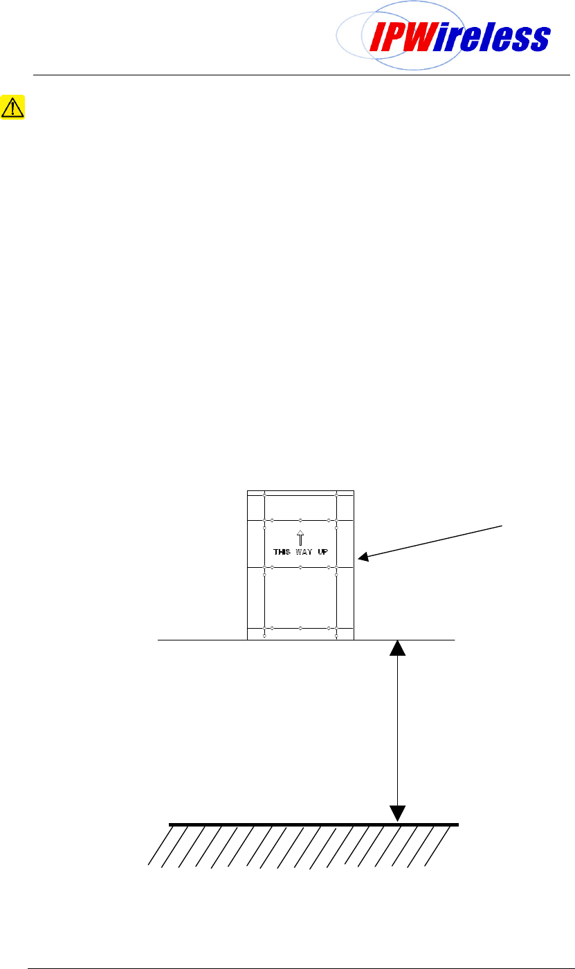
Position template and drill holes through template at appropriate positions as marked.
Ensure that the drill template position is vertical.
Figure 6-4: Drill template
Position drill
template and drill
1000mm (39.4inches)
Node B Installation Guide
Version 5.0.0 Page 17 of 37
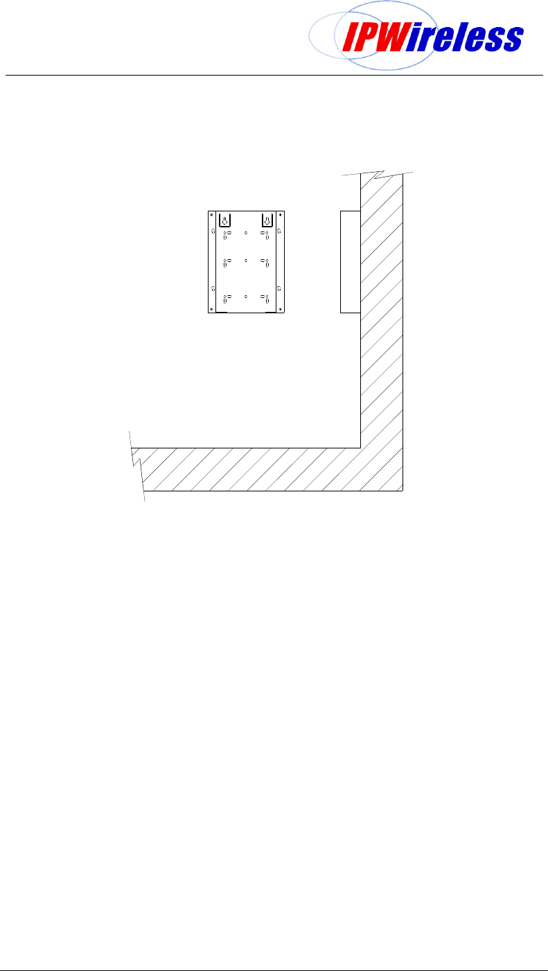
Securing Bracket to Wall – Flat Wall
Secure the bracket to the wall with 4off wall bolts (M8x55L Rawlok Loose bolt or equivalent).
Figure 6-5 : Bracket Fixing to Wall - Wall
Node B Installation Guide
Version 5.0.0 Page 18 of 37
Securing Bracket to Wall - Uneven Wall
To mount the bracket for an uneven wall the following materials are required:-
1. 2 pieces of P1000 HS x 14" Stainless Steel Unistrut™ Channel- locally supplied
2. 4off P1007 - 5/16”-18 UNC channel nuts with springs from Unistrut™ - locally supplied
3. 4off 5/16” x 1” – Hex Head Cap Screw Stainless Steel - Unistrut™ PN: HSHS031100EG
or equivalent - locally supplied
4. 4off 5/16” – Plain washer Stainless Steel - Unistrut™ PN: HFLW031EG or equivalent -
locally supplied
5. 4off 5/16” - Lock washer Stainless Steel - Unistrut™ PN: HFKW031EG or equivalent -
locally supplied
6. 4off M8x55L Rawlok Loose bolt or equivalent (eg. Hilti anchor bolts) - locally supplied
7. Drill & Masonary Drill Bit
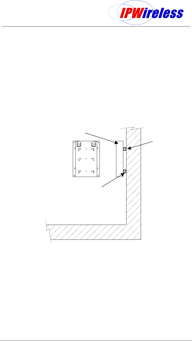
The following diagram illustrates the installation using the Unistrut method:- the drill template
can be used to position the drill holes
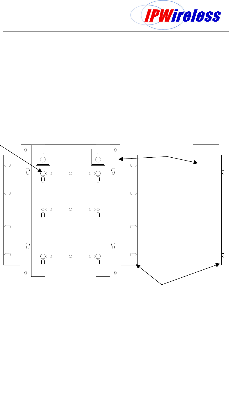
Figure 6-6: Node B Securing to Uneven Wall
4off M8 Wall anchor bolts
2off - 360mm (14inch) Unistrut channel
+
4off - Unistrut channel nuts w spring
Node B Bracket
Node B Installation Guide
Version 5.0.0 Page 19 of 37
Pole Mounting
This section specifies a suggested pole mount scheme using Unistrut components, and
equivalent system can be used where available more readily locally.
The Unistrut system can as standard cater for pole diameters up to 10inch (250mm).
To mount the bracket for a pole the following materials are required:-
1. 2 pieces of P1001Bx14" A2-304 Stainless Steel Unistrut™
2. 4off P1007 - 5/16”-18 UNC channel nuts with springs from Unistrut™ - locally supplied
3. 4off 5/16” x 1” UNC – Hex Head Cap Screw - Unistrut™ PN: HSHS031100EG or
equivalent - locally supplied
4. 4off 5/16” – Plain washer Stainless Steel - Unistrut™ PN: HFLW031EG or equivalent -
locally supplied
5. 4off 5/16” - Lock washer Stainless Steel - Unistrut™ PN: HFKW031EG or equivalent -
locally supplied
6. 2off Cush-A-Clamp Sets (2-6inch) or U-Bolt Series (< 12inch)– see Unistrut™ catalogue
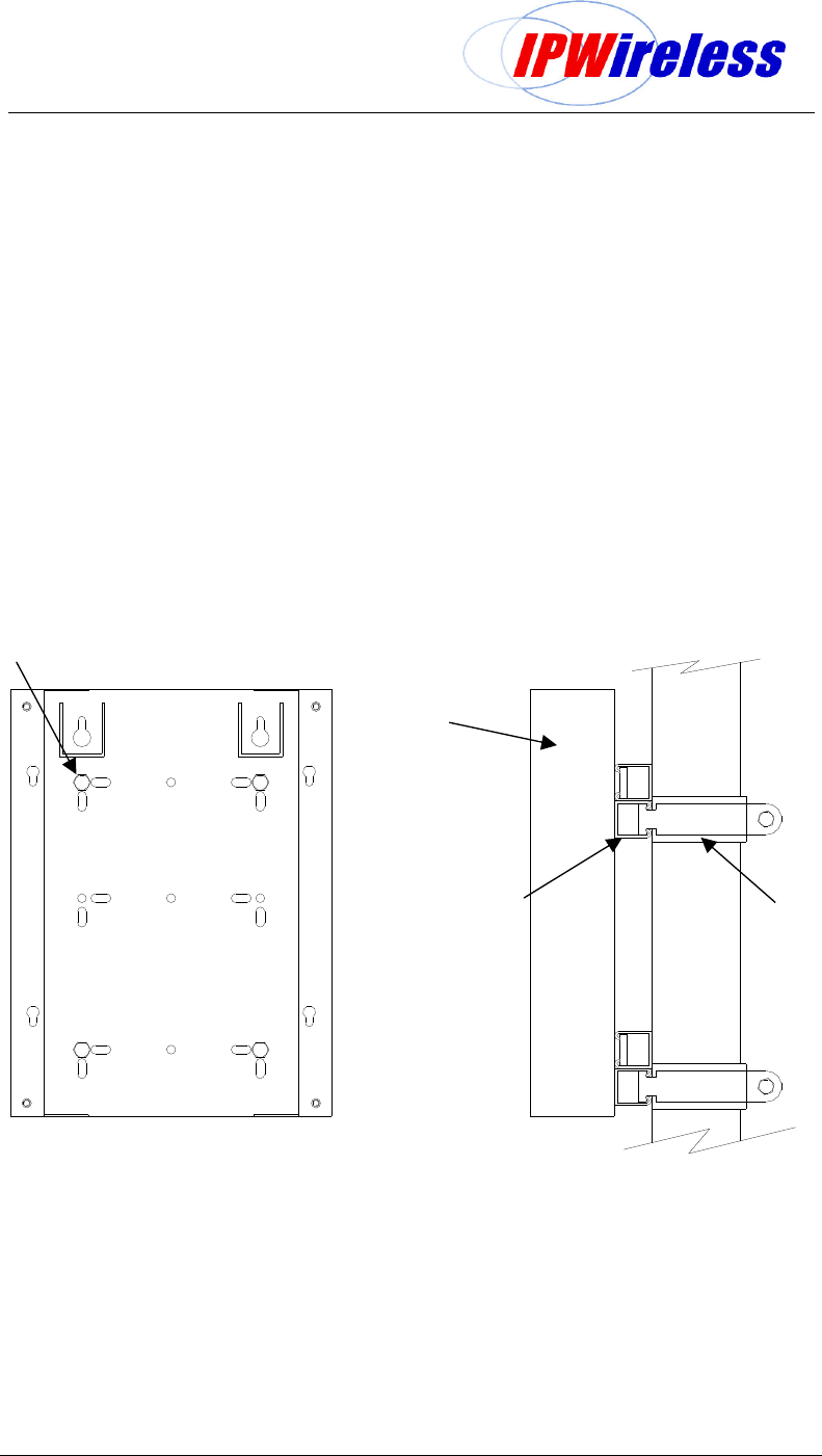
The following diagram illustrates the installation using the Unistrut method:-
Figure 6-7 : Pole Mounting using Unistrut systems
Note: Where a Node B is required to be mounted to a pole greater than 10inch or to an
irregular shaped mast eg. Hexagonal, banding may required to be used. In this situation
contact your IPWireless field support for guidance.
Node B Bracket
2off - 360mm (14inch)
Dual-Unistrut channel
+
4off - Unistrut channel
nuts w spring
2off – Unistrut pole mounts
Cush-A-Clamp
Or
U-Bolt Series
5/16” x 1” UNC –
- Hex Head Cap Screw
- Lock Washer
- Plain Washer
Node B Installation Guide
Version 5.0.0 Page 20 of 37
Rack Mount
This section describes the mounting of the Node B bracket into a rack. The following
mounting materials are required to secure the bracket into a rack. The figure below
illustrates a typical installation, rack not shown.
1. Plate (9U x 19inch shown) or U-channels to mount the bracket onto standard 19" or
23"
2. 4off M8x20 Hex Head Cap Screw + 8off M8 Plain washer + 8off M8 Lock Washer +
4off M8 Nuts
3. 8 off Cage nuts + Screws – note these are required to secure the plate to the rack
(not shown)
Figure 6-8 : Node B - Rack Mounted
Node B Bracket
M8 Fixings –
- Hex Head Cap Screw
- Lock Washer
- Plain Washer 2off
- Nut
19inch 9U Plate
Node B Installation Guide
Version 5.0.0 Page 21 of 37
Physical Installation of the Node B
This section describes the installation of the Node into the mounting bracket and the
connection of the power and interface cables.
Step 5 Conduit Installation & Cabling
Where the Node B is installed into an outdoor installation all power and IUB cable must be
routed to/from the Node B via conduit.
Where the Node B has to be connected to an outdoor installation of an INC conduit is
required between the INC and power source. (Refer to the INC Installation Guide)
Power and Ethernet cables are to be pulled through the conduit, one power cable and one
Ethernet (or E3, T3, E1, or T1) cable(s) for each Node B.
Where external alarms are to be utilized conduit shall also be necessary between the
external alarm device and the Node B for monitoring the alarm.
The cables need to be fed through the conduit and into the Node B via the cable glands
(supplied) excess cable left for termination. Leave a sufficient loop of cables to enable them
to be prepared back to the appropriate length.
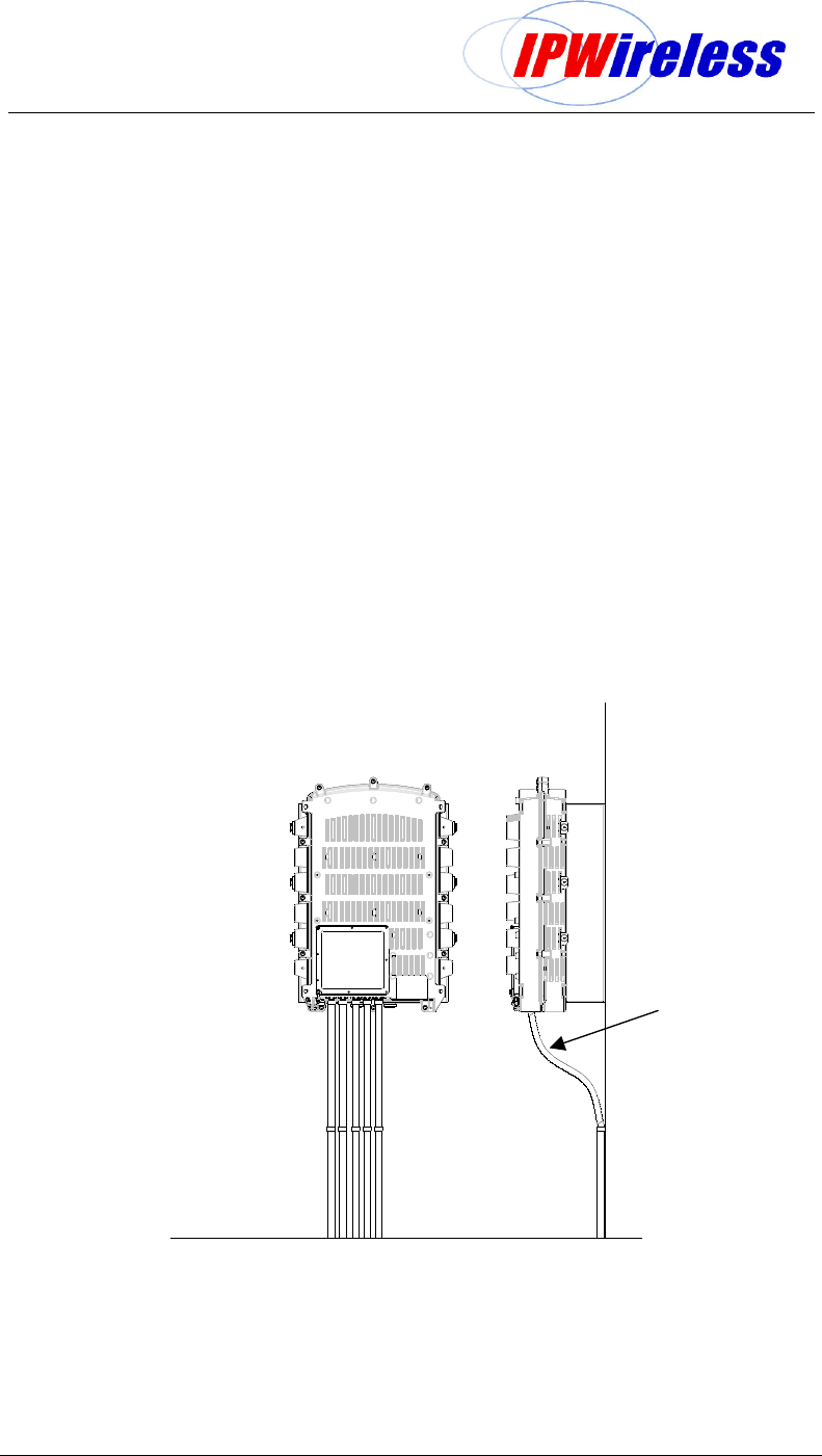
The figure below illustrates a typical conduit installation.
Figure 6-9: Flexible Conduit
Flexible conduit
Node B Installation Guide
Version 5.0.0 Page 22 of 37
Step 6 Node B Installation onto Mounting Bracket
This section describes how to mount and secure the Node B to the mounting bracket. The
figure below illustrates the following steps
1. Align the top long dowel pins with top holes in bracket.
2. Insert Node B into the bracket
3. Ensure all dowels are inserted, if not repeat 1 & 2
4. Lower Node B into the keyslots
5. Secure Node B to bracket using 4 x M8 bolts & washers provided.
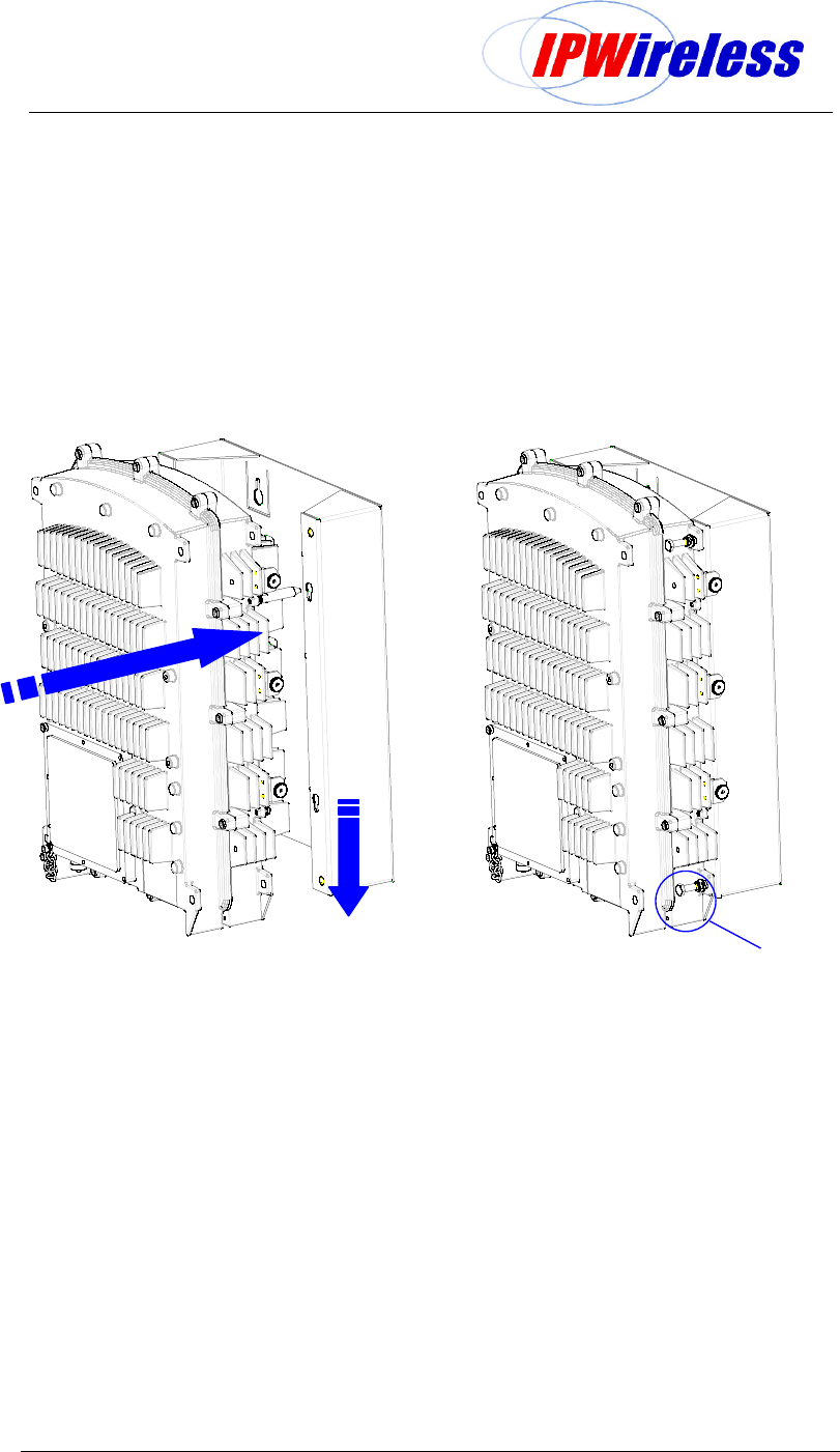
Figure 6-10: Node B onto Mounting Bracket
INSERT
Node B
Onto
Bracket
Once inserted
LOWER Node B
Secure Node B using M8 bolts
+ washers each corner
Node B Installation Guide
Version 5.0.0 Page 23 of 37
Step 7 Ground Installation
The main Node B ground cable shall use a minimum #2 AWG (Diameter 6.6mm or CSA
33mm2) stranded wire or equivalent earth braid.
The ground cable is terminated on the Node B using terminal that shall fit the M10 (7/16”)
bolt provided. The ground bolt can be position on either side and/or rear of the Node B.
The grounding wire is terminated onto the site grounding ring.
It should be noted that each site shall be designed for specific site, country or local
installation requirements.
CAUTION: Ensure that the earth braid or cable is bonded to a common earth with
equipment that is co-located with the Node B.
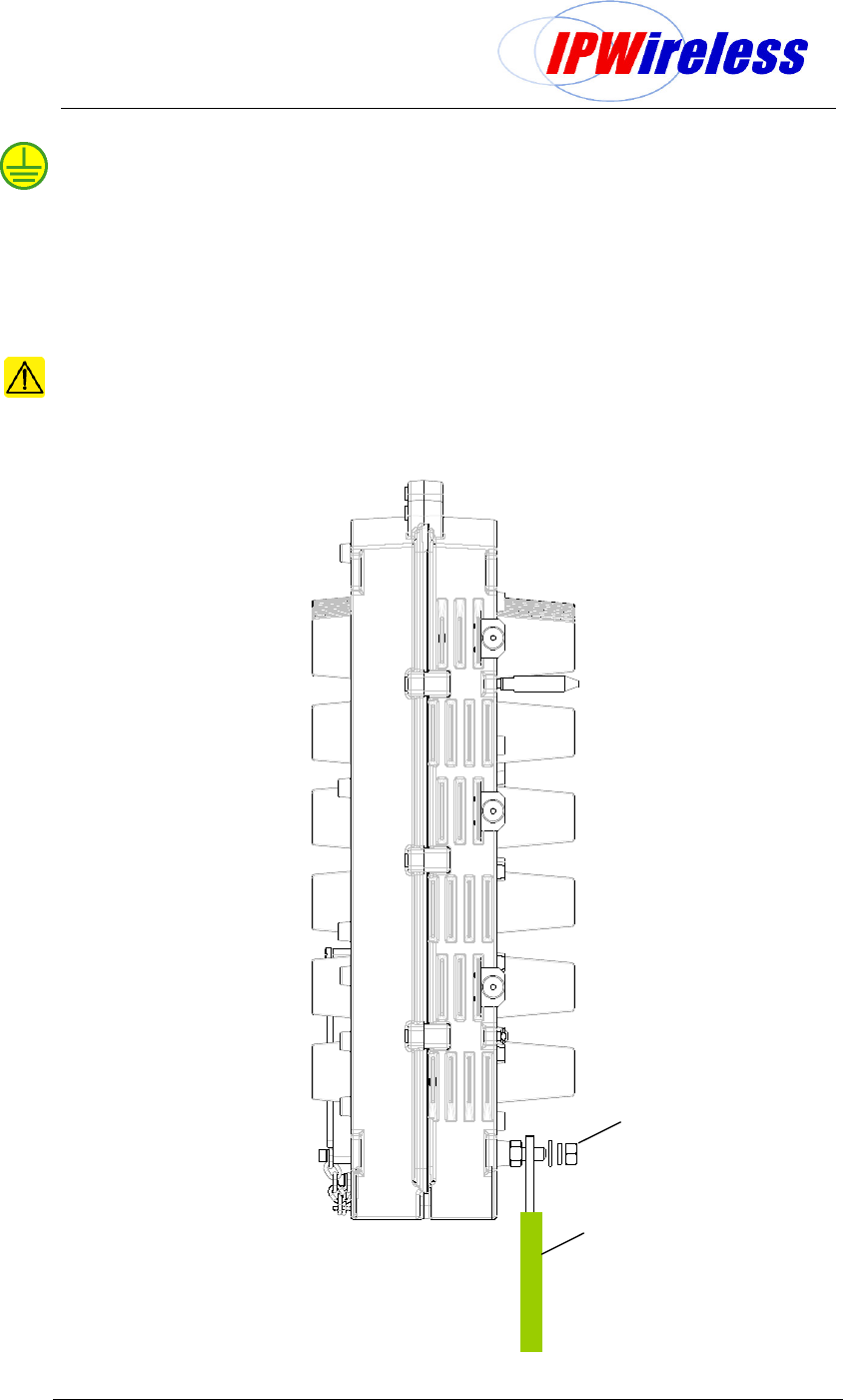
Figure 6-11 : Earth Connection
Secure Earth Terminal using
Node B using M10 nut + washers
Earth Braid
Node B Installation Guide
Version 5.0.0 Page 24 of 37
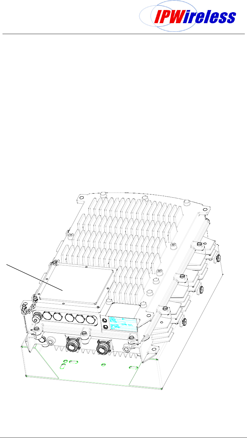
Step 8 Service Cover Access
The service cover permits access to power, backhaul, alarm and debug interfaces of the
Node B as listed below.
Mains DC supply
IUB Interfaces – Ethernet, E1, T1, E3 or T3
Alarm Interfaces – input & output
Status - 7 Segment Display
Status – LEDs
Debug port
Switches
To gain access loosen the peripheral fixings as illustrated in the figure below using the
special tool provided. Once the cover has been loosened the access cover can be left to
hang by the chain while installation proceeds.
Figure 6-12 : Service Access
Loosen Fixings
around periphery
of service cover
Node B Installation Guide
Version 5.0.0 Page 25 of 37
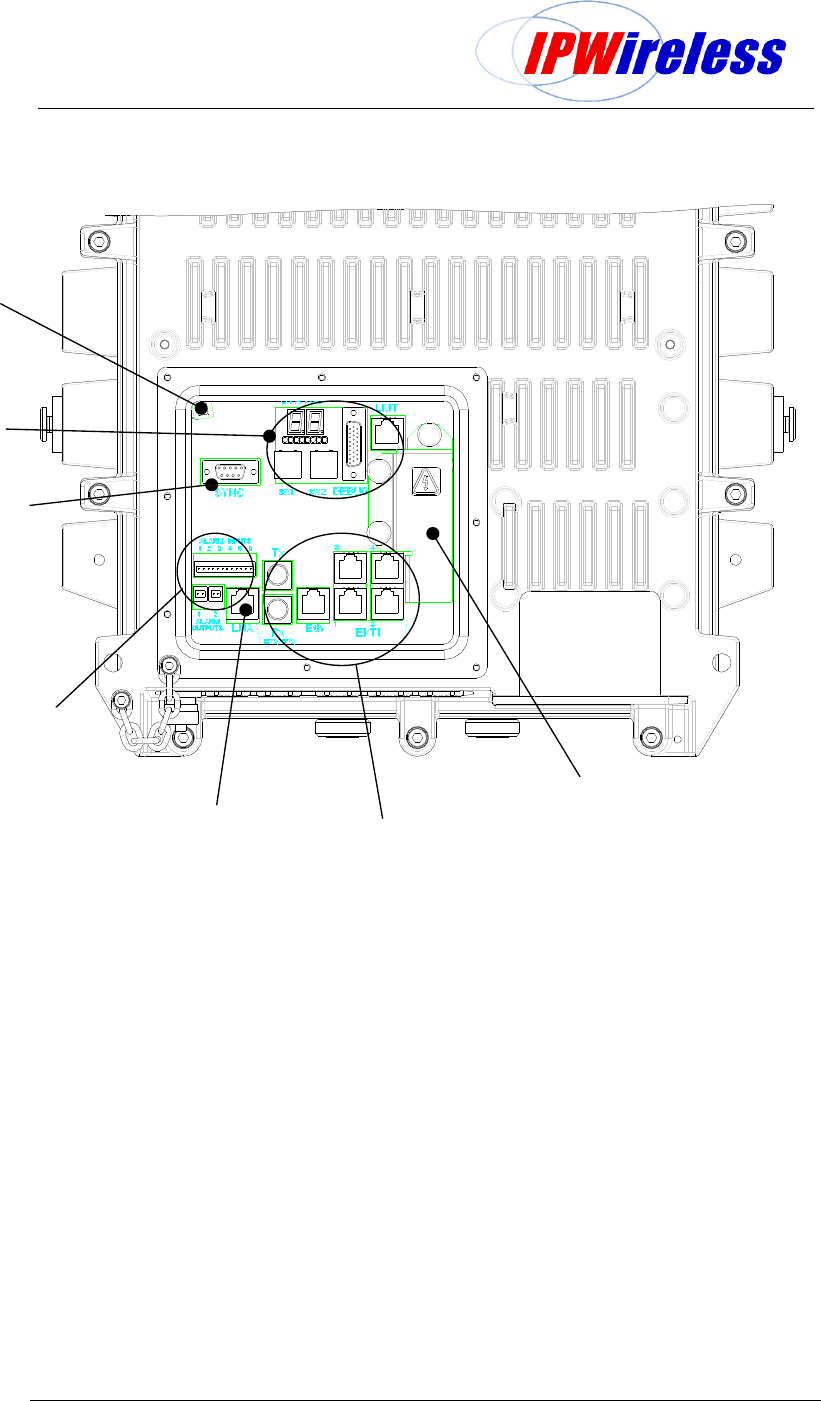
The figure below illustrates the service cover removed and highlights the interfaces.
Figure 6-13 : Service Area Description
Power Cover
Iub Interfaces
Optional
LNA
Interface
External Alarms
Interface
Node B
Synchronisation
Interface
Installation
& Debug
Interfaces
Service
Cover Door
Switch