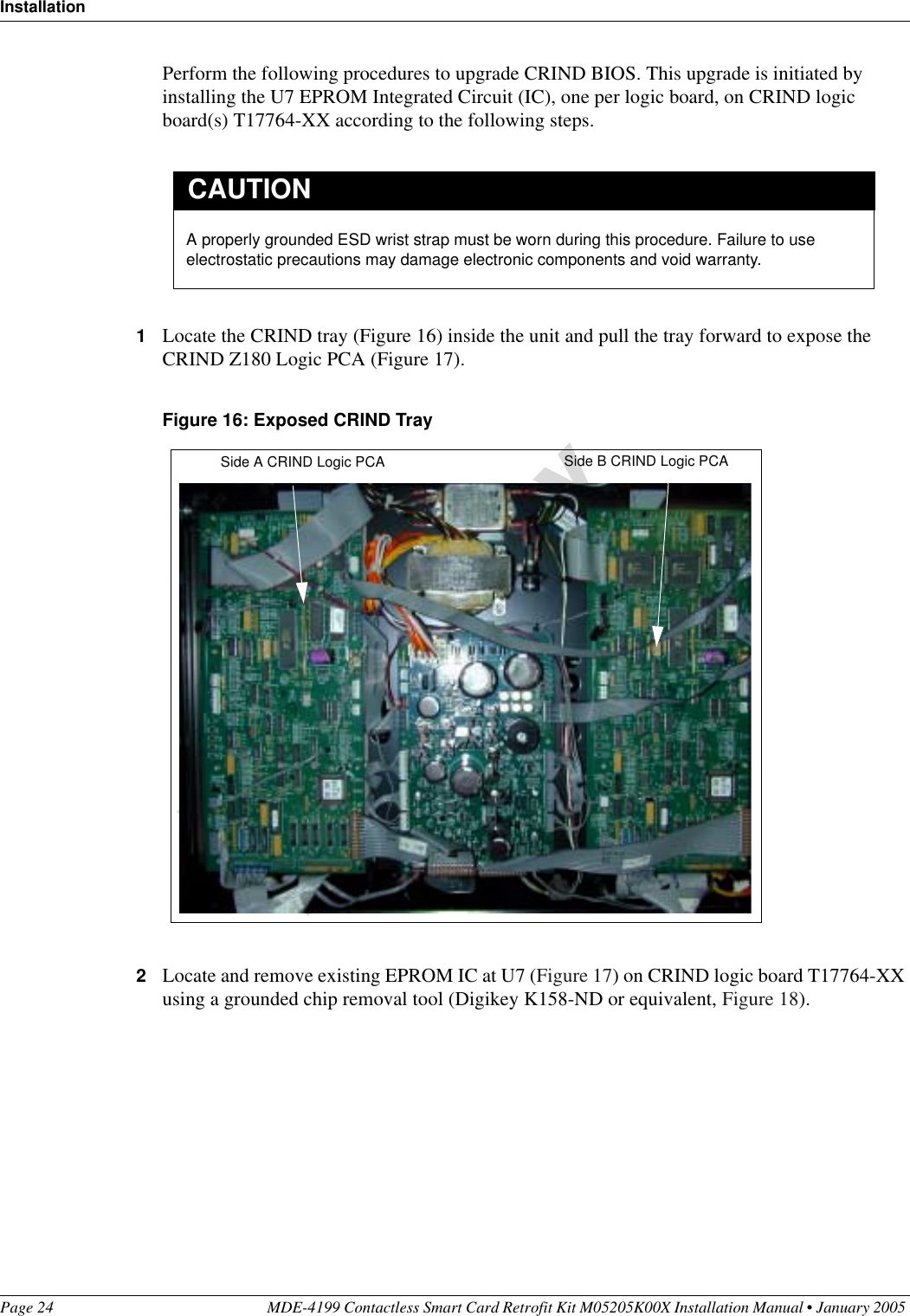
Gilbarco GBIR14 M03312B001 Card Reader User Manual
Gilbarco Inc. M03312B001 Card Reader
UserManual.wiki
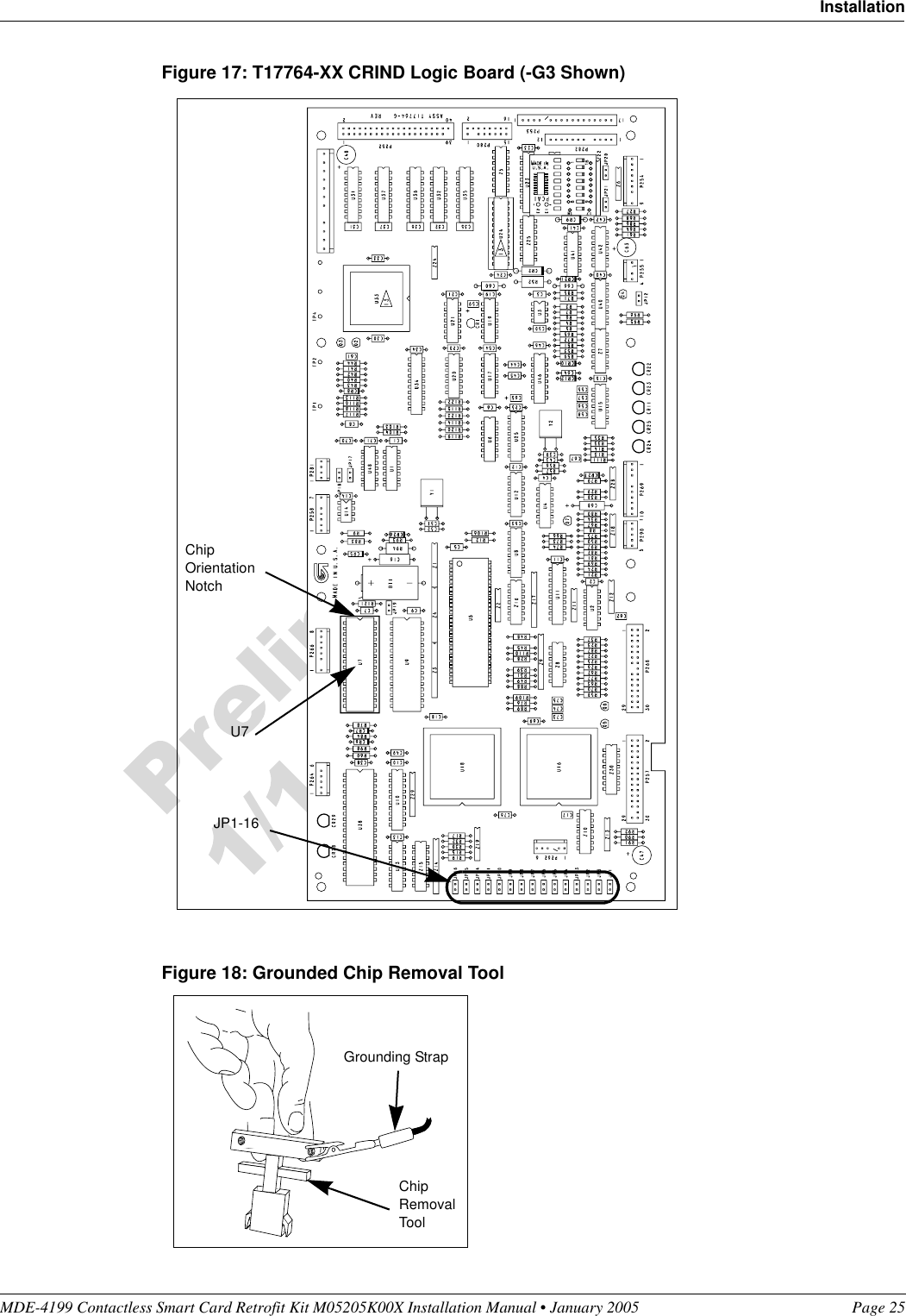
>
Gilbarco
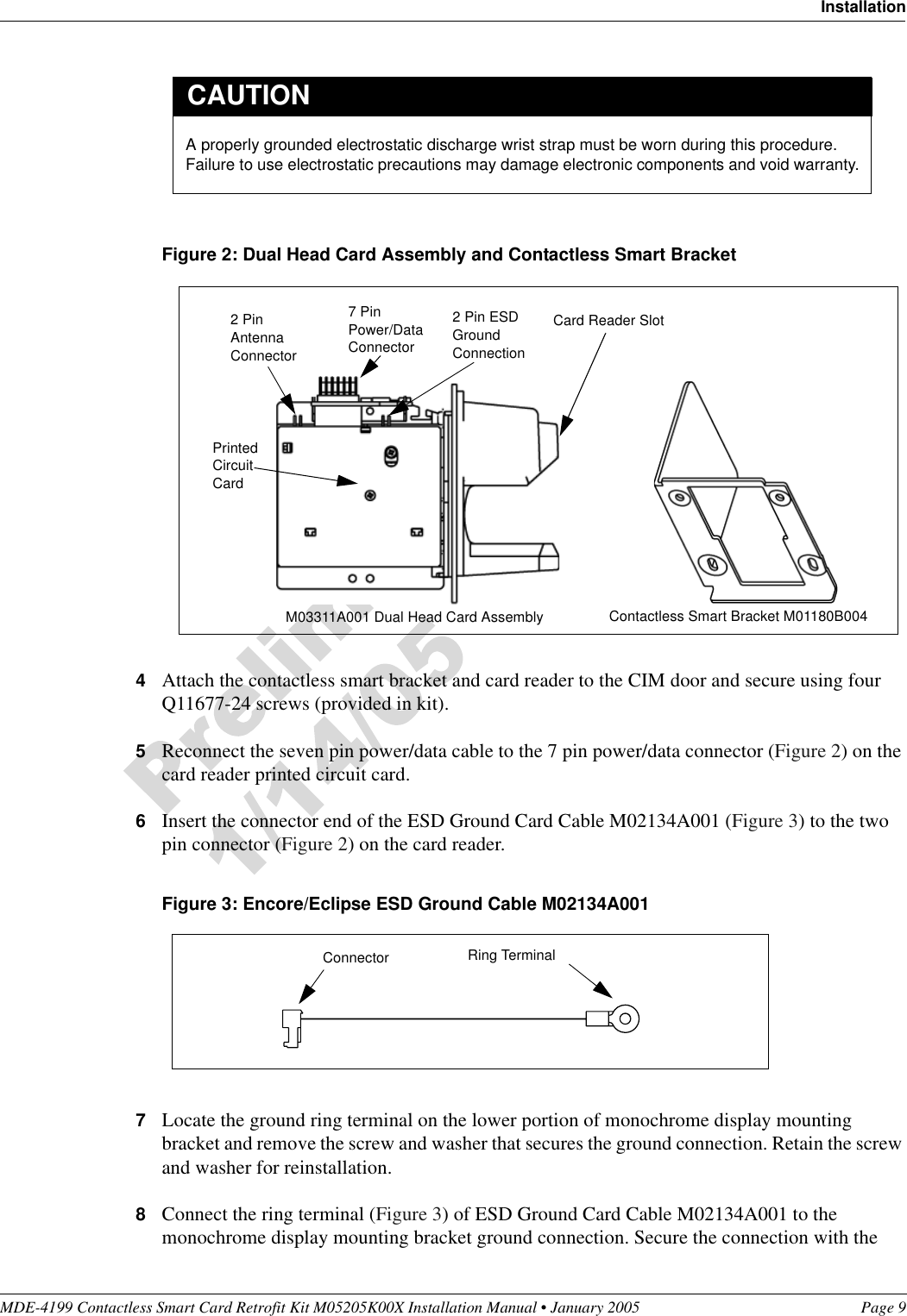
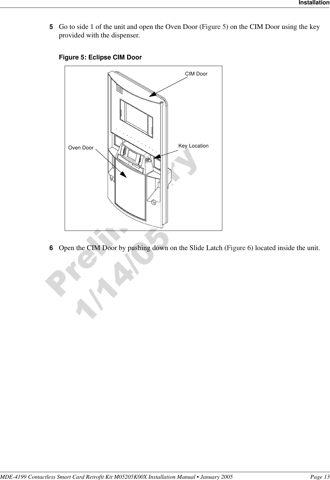
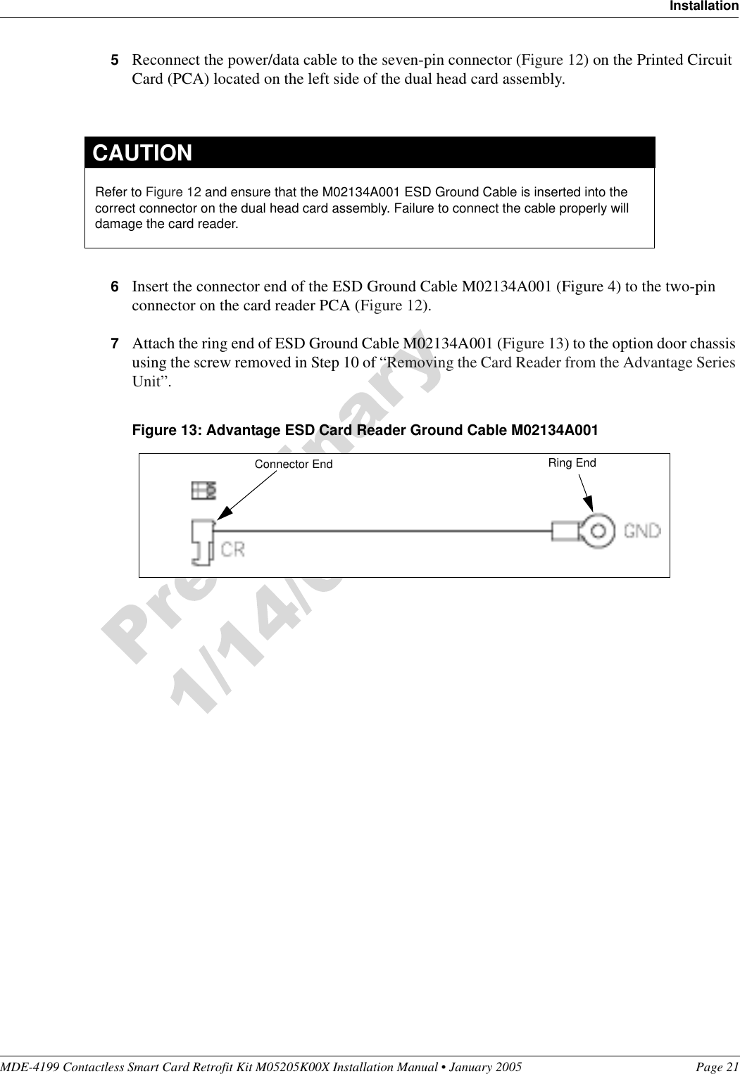
>
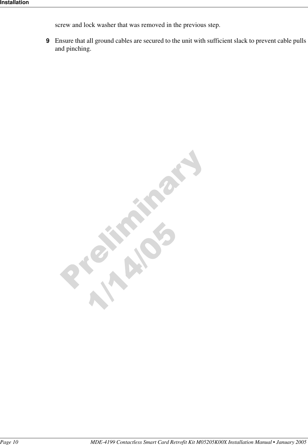
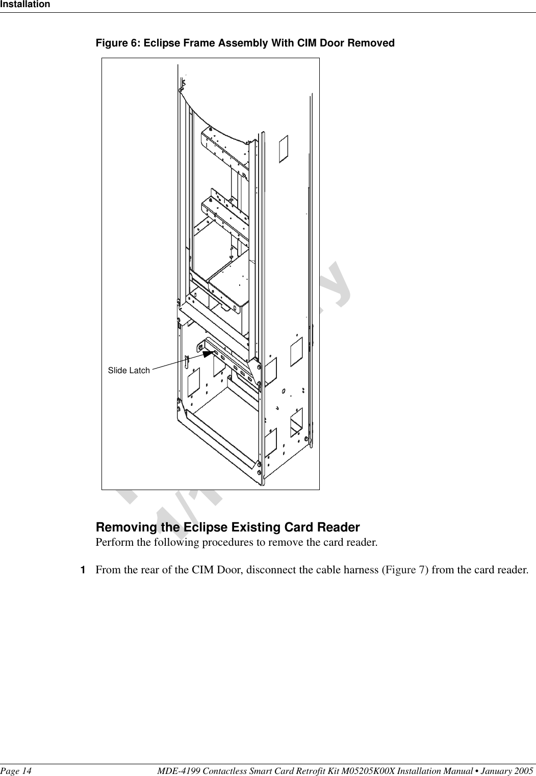
GBIR14 User Manual
Manual
Navigation menu
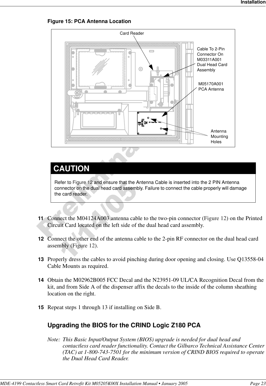
Upload a User Manual
Namespaces
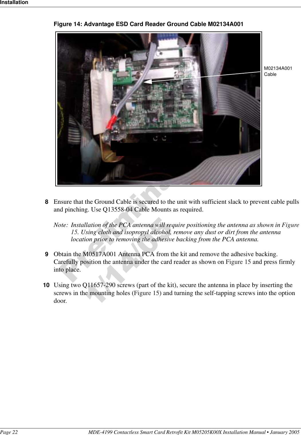
Wiki Guide
HTML
PDF
Info
Views
User Manual
Discussion / Help
Navigation