Gilbarco GBIR16 Card Reader Transmitter User Manual MDE 4635
Gilbarco Inc. Card Reader Transmitter MDE 4635
Gilbarco >
users manual

MDE-4635 Encrypted Card Reader Retrofit Kit (M07813K00X) Installation Manual · May 2007 Page 1
Preliminary
05/15/07
Introduction
Purpose This manual provides installation instructions for M07813K00X Encrypted Card Reader
Retrofit Kits. The kits are used in the following units:
Unit Type Kit Number
Encore® S (Encrypted Contactless Card Reader) M07813K001
Encore S (Encrypted Card Reader) M07813K002
Encore 500 (Encrypted Contactless Card Reader) M07813K003
Encore 500 (Encrypted Card Reader) M07813K004
Encore 300 (Encrypted Contactless Card Reader) M07813K005
Encore 300 (Encrypted Card Reader) M07813K006
The Advantage (Encrypted Contactless Card Reader) Series dispensers with
Infoscreen, Monochrome, or Single-line with American Disabilities Act (ADA) Card
Reader in Dispenser (CRIND®) features and using space reserved for cash acceptor
M07813K007
The Advantage (Encrypted Contactless Card Reader) Series dispensers with
Infoscreen, Monochrome, or Single-line with ADA CRIND features and reserving the
space for cash acceptor
M07813K008
The Advantage® (Encrypted Card Reader) Series dispensers with Infoscreen®,
Monochrome, or Single-line with ADA CRIND features
M07813K009
The Encrypted Card Reader option provides protection against theft.
Note: This feature requires that the dispenser subject to installation contains the Card Reader
option. Door replacements that contain aluminum CRIND doors or pre-ADA doors may
be required for the Advantage Series dispensers.
MDE-4635
Encrypted Card Reader Retrofit Kit (M07813K00X)
Installation Manual
May 2007

Introduction
Page 2 MDE-4635 Encrypted Card Reader Retrofit Kit (M07813K00X) Installation Manual · May 2007
Preliminary
Table of Contents
Topic Page
Introduction 1
Purpose 1
Table of Contents 2
Required Reading 2
Related Documents 8
Parts Lists 3
Important Safety Information 9
Installation of the Encrypted Card Reader Retrofit Kit 11
Installing the M07813K001 Kit in an Encore S Unit (with Contactless Card Reader Option) 11
Installing the M07813K002 Kit in an Encore S Unit (without Contactless Card Reader Option) 19
Installing the M07813K003 Kit in an Encore 500 Unit (with Contactless Card Reader Option) 19
Installing the M07813K004 Kit in an Encore 500 Unit (without Contactless Card Reader Option) 26
Installing the M07813K005 Kit in an Encore 300 Unit (with Contactless Card Reader Option) 27
Installing the M07813K006 Kit in an Encore 300 Unit (without Contactless Card Reader Option) 34
Installing the M07813K007 Kit in an Advantage Series Unit Using Space Reserved for Cash
Acceptor (with Contactless Card Reader Option)
35
Installing the M07813K008 Kit in an Advantage Series Unit Reserving Space for Cash Acceptor
(with Contactless Card Reader Option)
44
Installing the M07813K009 Kit in an Advantage Series Unit Using Space Reserved for Cash
Acceptor on the Left Options Door (without Contactless Card Reader Option)
48
Required Reading
Before installing this kit, the installer must read, understand, and follow:
• This manual
• NFPA 30A, The Automotive and Marine Service Station Code
• NFPA 70, The National Electric Code
• Applicable federal, state, and local codes and regulations
Failure to do so may adversely affect the safe use and operation of the equipment.
Note: This kit must be installed by a Gilbarco Authorized Service Contractor (ASC) to ensure
warranty.
Required Tools
The following tools are required to install the Encrypted Card Reader (ECR) Retrofit Kit:
• IC Extraction Tool, Digikey K158-ND (or equivalent)
• IC Extraction Tool, AMP 821903-1 (or equivalent)
• Isopropyl alcohol (END-1082)
• Nut drivers, 1/4-inch, 8 mm, 3/8-inch, 9/32-inch
• Putty knife
• CSC test card
• Ratchet set, standard
• Screwdrivers, flat blade and cross tip
• Static guard wrist strap

MDE-4635 Encrypted Card Reader Retrofit Kit (M07813K00X) Installation Manual · May 2007 Page 3
Introduction
Preliminary
Parts Lists The following tables provide the parts list information for the Encrypted Card Reader Retrofit
Kits.
Encore S Encrypted Contactless Card Reader Kit (M07813K001)
Item Description Part Number Quantity
1Encrypted Card Reader M07577B001 2
2Cable, ESD Ground Card M07709A002 2
3PCA, 13.5 MHz Antenna M05170A001 2
4Decal, FCC/IC Recognition N23951-11 2
5Cable, Antenna Eccore/ADV M07703A001 2
6Bracket, Contactless Smart M07573B001 2
7Gasket, Card Reader M00682B003 2
8Screw SEL TP HEX HD 6-20X Q11677-24 4
9Tape Foam - 2 inch pieces K85492-56 4
10 Lens, TRIND® CSC Reader M05987B002 2
11 Screw Metric M4 X 8 M00419B117 8
12 Gasket, TRIND, ECE M06010B002 2
13 Cable, ECR/SmartPad Interface M07702A001 2
14 Cable Mount, Adhesive Q13558-04 6
15 Card, Card Reader Cleaning Q11482 1
16 Decal, Patent and FCC M02962B009 1
17 CCN Software (Download) V03.1 -
18 Encrypted Card Reader, Installation Manual MDE-4635 1
Item Description Part Number Quantity
1Encrypted Card Reader M07577B001 2
2Cable, ESD Ground Card M07709A002 2
3Bracket, Contactless Smart M07573B001 2
4Gasket, Card Reader M00682B003 2
5Screw SEL TP HEX HD 6-20X Q11677-24 4
6Cable, ECR/SmartPad Interface M07702A001 2
7Cable Mount, Adhesive Q13558-04 6
8Card, Card Reader Cleaning Q11482 1
9CCN Software (Download) V03.1 -
10 Encrypted Card Reader, Installation Manual MDE-4635 1
Encore S Encrypted Card Reader Kit (M07813K002)

Introduction
Page 4 MDE-4635 Encrypted Card Reader Retrofit Kit (M07813K00X) Installation Manual · May 2007
Preliminary
Encore 500 Encrypted Contactless Card Reader Kit (M07813K003)
Item Description Part Number Quantity
1Encrypted Card Reader M07577B001 2
2Cable, ESD Ground Card M07709A001 2
3PCA, 13.5 MHz Antenna M05170A001 2
4Decal, FCC/IC Recognition N23951-11 2
5Cable, Antenna Eccore/ADV M07703A001 2
6Bracket, Card Reader M07574B001 2
7Gasket, Card Reader M00682B001 2
8Screw SEL TP HEX HD 6-20X Q11677-24 8
9Screw TF WSHR HEX HD CS Q11657-290 4
10 Tape Foam - 2 inch pieces K85492-56 4
11 Cable, ECR/SmartPad Interface M07702A003 2
12 Cable Mount, Adhesive Q13558-04 6
13 Card, Card Reader Cleaning Q11482 1
14 Decal, Patent and FCC M02962B009 1
15 CCN Software (Download) V03.1 -
16 Encrypted Card Reader, Installation Manual MDE-4635 1
Encore 500 Encrypted Card Reader Kit (M07813K004)
Item Description Part Number Quantity
1Encrypted Card Reader M07577B001 2
2Cable, ESD Ground Card M07709A001 2
3Bracket, Card Reader M07574B001 2
4Gasket, Card Reader M00682B001 2
5Screw SEL TP HEX HD 6-20X Q11677-24 8
6Cable, ECR/SmartPad Interface M07702A003 2
7Cable Mount, Adhesive Q13558-04 6
8Card, Card Reader Cleaning Q11482 1
9CCN Software (Download) V03.1 -
10 Encrypted Card Reader, Installation Manual MDE-4635 1

MDE-4635 Encrypted Card Reader Retrofit Kit (M07813K00X) Installation Manual · May 2007 Page 5
Introduction
Preliminary
Encore 300 Encrypted Contactless Card Reader Kit (M07813K005)
Item Description Part Number Quantity
1Encrypted Card Reader M07577B001 2
2Cable, ESD Ground Card M07709A001 2
3PCA, 13.5 MHz Antenna M05170A001 2
4Decal, FCC/IC Recognition N23951-11 2
5Cable, Antenna Eccore/ADV M07703A001 2
6Bracket, Card Reader M07574B001 2
7Gasket, Card Reader M00682B003 2
8Screw SEL TP HEX HD 6-20X Q11677-24 8
9Screw TF WSHR HEX HD CS Q11657-290 4
10 Tape Foam - 2 inch pieces K85492-56 4
11 Cable, ECR/SmartPad Interface M07702A002 2
12 Cable Mount, Adhesive Q13558-04 6
13 Card, Card Reader Cleaning Q11482 1
14 Decal, Patent and FCC M02962B009 1
15 Software CRIND BIOS V60.X.XX K93744-02 1*
16 Software CRIND BIOS V62.X.XX KXXXXX-XX 1**
17 Encrypted Card Reader, Installation Manual MDE-4635 1
* Without SmartPad
** With SmartPad
Encore 300 Encrypted Card Reader Kit (M07813K006)
Item Description Part Number Quantity
1Encrypted Card Reader M07577B001 2
2Cable, ESD Ground Card M07709A001 2
3Bracket, Card Reader M07574B001 2
4Gasket, Card Reader M00682B001 2
5Screw SEL TP HEX HD 6-20X Q11677-24 8
6Cable, ECR/SmartPad Interface M07702A002 2
7Cable Mount, Adhesive Q13558-04 6
8Card, Card Reader Cleaning Q11482 1
9Software CRIND BIOS V60.X.XX K93744-02 1*
10 Software CRIND BIOS V62.X.XX KXXXXX-XX 1**
11 Encrypted Card Reader, Installation Manual MDE-4635 1
* Without SmartPad
** With SmartPad

Introduction
Page 6 MDE-4635 Encrypted Card Reader Retrofit Kit (M07813K00X) Installation Manual · May 2007
Preliminary
Advantage Series Encrypted Contactless Card Reader Kit (M07813K007)
Using Space Reserved for Cash Acceptor
Item Description Part Number Quantity
1Encrypted Card Reader M07577B001 2
2Cable, ESD Ground Card M07709A003 2
3PCA, 13.5 MHz Antenna M05170A001 2
4Cable, Antenna Eccore/ADV M07703A001 2
5Bracket, Card Reader M07576B001 2
6Gasket, Card Reader N23505-02 2
7Screw SEL TP HEX HD 6-20X Q11677-24 8
8Screw TF WSHR HEX HD CS Q11657-290 4
9Cable Tie Q10178-02 2
10 Tape Foam - 2 inch pieces K85492-56 4
11 Cable, ECR/SmartPad Interface M07702A004 2
12 Cable Mount, Adhesive Q13558-04 18
13 Clamp, Cable Mounting Q13459-01 2
14 Card, Card Reader Cleaning Q11482 1
15 Decal, FCC/IC Recognition N23951-11 2
16 Decal, Patent and FCC M02962B009 1
17 Software CRIND BIOS V60.X.XX K93744-02 1*
18 Software CRIND BIOS V62.X.XX KXXXXX-XX 1**
19 Encrypted Card Reader, Installation Manual MDE-4635 1
* Without SmartPad
** With SmartPad

MDE-4635 Encrypted Card Reader Retrofit Kit (M07813K00X) Installation Manual · May 2007 Page 7
Introduction
Preliminary
Advantage Series Encrypted Contactless Card Reader Kit (M07813K008)
Reserving Space for Cash Acceptor
Item Description Part Number Quantity
1Encrypted Card Reader M07577B001 2
2Cable, ESD Ground Card M07709A003 2
3PCA, 13.5 MHz Antenna M05170A001 2
4Cable, Antenna Eccore/ADV M07703A002 2
5Bracket, Card Reader M07576B001 2
6Gasket, Card Reader N23505-02 2
7Screw SEL TP HEX HD 6-20X Q11677-24 8
8Screw TF WSHR HEX HD CS Q11657-290 4
9Cable Tie Q10178-02 2
10 Tape Foam - 2 inch pieces K85492-56 4
11 Cable, ECR/SmartPad Interface M07702A004 2
12 Cable Mount, Adhesive Q13558-04 6
13 Clamp, Cable Mounting Q13459-01 2
14 Card, Card Reader Cleaning Q11482 1
15 Decal, FCC/IC Recognition N23951-11 2
16 Decal, Patent and FCC M02962B009 1
17 Software CRIND BIOS V60.X.XX K93744-02 1*
18 Software CRIND BIOS V62.X.XX KXXXXX-XX 1**
19 Encrypted Card Reader, Installation Manual MDE-4635 1
* Without SmartPad
** With SmartPad
Advantage Series Encrypted Card Reader Kit (M07813K009) Using Space
for Cash Acceptor
Item Description Part Number Quantity
1Encrypted Card Reader M07577B001 2
2Cable, ESD Ground Card M07709A003 2
3Bracket, Card Reader M07576B001 2
4Gasket, Card Reader N23505-02 2
5Screw SEL TP HEX HD 6-20X Q11677-24 8
6Cable, ECR/SmartPad Interface M07702A004 2
7Cable Mount, Adhesive Q13558-04 6
8Clamp, Cable Mounting Q13459-01 2
9Card, Card Reader Cleaning Q11482 1
10 Software CRIND BIOS V60.X.XX K93744-02 1*
11 Software CRIND BIOS V62.X.XX KXXXXX-XX 1**
12 Encrypted Card Reader, Installation Manual MDE-4635 1
* Without SmartPad
** With SmartPad

Standard Encore units manufactured after January 1, 2005 may not have openings in
the customer interface door for Scanner, Cash Acceptor, or Transmitter/Receiver In
Dispenser (TRIND)/Contactless. If your unit was built after January 1, 2005 and does
not have these openings, it will require the installation of an M01208A00X Customer
Interface Module (CIM™) door with CRIND device and CIM graphics to install a
Contactless Smart Card Retrofit Kit. Verify the unit’s date code prior to installation.
Refer to MDE-3893 Encore and Eclipse® Series Owner’s Manual for details on
understanding the date codes.
IMPORTANT INFORMATION
Introduction
Page 8 MDE-4635 Encrypted Card Reader Retrofit Kit (M07813K00X) Installation Manual · May 2007
Preliminary
Related Documents
Document
Number Title GOLD Library
MDE-2540 The Advantage®, Legacy®, and MPD® Series Owner’s
Manual
The Advantage and Legacy Models
MDE-2562 CRIND Service Manual CRIND and TRIND
MDE-3804 Encore and Eclipse Series Start-Up/Service Manual Encore and Eclipse
MDE-3893 Encore/Eclipse Owners Manual Encore and Eclipse
MDE-4516 Encore S Series Owner's Manual Encore and Eclipse
MDE-4625 Graphics Panel Application and Repair Encore and Eclipse
PT-1728 The Advantage Series Illustrated Parts Manual Parts Manual
PT-1736 CRIND Illustrated Parts Manual Parts Manual
PT-1936 Encore Series Pump and Dispenser Illustrated Parts Manual Parts Manual
PT-1938 Eclipse Series Pump and Dispenser Parts Manual Parts Manual
Abbreviations and Acronyms
Term Description
ADA American Disabilities Act
CRIND Card Reader in Dispenser
CSC Contactless Smart Card
ESD Electrostatic Discharge
PCA Printed Circuit Assembly
POS Point of Sale
RF Radio Frequency
TRIND Transmitter/Receiver in Dispenser
MDE-4635 Encrypted Card Reader Retrofit Kit (M07813K00X) Installation Manual · May 2007 Page 9
Important Safety Information
Preliminary
Important Safety Information
This section introduces the hazards and safety precautions
associated with installing, inspecting, maintaining or servicing
this product. Before performing any task on this product, read
this safety information and the applicable sections in this
manual, where additional hazards and safety precautions for
your task will be found. Fire, explosion, electrical shock or
pressure release could occur and cause death or serious
injury, if these safe service procedures are not followed.
Preliminary Precautions
You are working in a potentially dangerous environment of
flammable fuels, vapors, and high voltage or pressures. Only
trained or authorized individuals knowledgeable in the related
procedures should install, inspect, maintain or service this
equipment.
Emergency Total Electrical Shut-Off
The first and most important information you must know is
how to stop all fuel flow to the pump/dispenser and island.
Locate the switch or circuit breakers that shut off all power to
all fueling equipment, dispensing devices, and Submerged
Turbine Pumps (STPs).
Total Electrical Shut-Off Before Access
Any procedure that requires access to electrical components
or the electronics of the dispenser requires total electrical
shut off of that unit. Understand the function and location of
this switch or circuit breaker before inspecting, installing,
maintaining, or servicing Gilbarco equipment.
Evacuating, Barricading and Shutting Off
Any procedure that requires access to the pump/dispenser or
STPs requires the following actions:
• An evacuation of all unauthorized persons and vehicles
from the work area
• Use of safety tape, cones or barricades at the affected
unit (s)
• A total electrical shut-off of the affected unit (s)
Read the Manual
Read, understand and follow this manual and any other
labels or related materials supplied with this equipment. If you
do not understand a procedure, call a Gilbarco Authorized
Service Contractor or call the Gilbarco Support Center at
1-800-800-7498. It is imperative to your safety and the safety
of others to understand the procedures before beginning
work.
Follow the Regulations
Applicable information is available in National Fire Protection
Association (NFPA) 30A; Code for Motor Fuel Dispensing
Facilities and Repair Garages, NFPA 70; National Electrical
Code (NEC), Occupational Safety and Hazard Association
(OSHA) regulations and federal, state, and local codes. All
these regulations must be followed. Failure to install, inspect,
maintain or service this equipment in accordance with these
codes, regulations and standards may lead to legal citations
with penalties or affect the safe use and operation of the
equipment.
Replacement Parts
Use only genuine Gilbarco replacement parts and retrofit kits
on your pump/dispenser. Using parts other than genuine
Gilbarco replacement parts could create a safety hazard and
violate local regulations.
Safety Symbols and Warning Words
This section provides important information about warning
symbols and boxes.
Alert Symbol
This safety alert symbol is used in this manual and
on warning labels to alert you to a precaution which must be
followed to prevent potential personal safety hazards. Obey
safety directives that follow this symbol to avoid possible
injury or death.
Signal Words
These signal words used in this manual and on warning
labels tell you the seriousness of particular safety hazards.
The precautions below must be followed to prevent death,
injury or damage to the equipment:
DANGER: Alerts you to a hazard or unsafe practice
which will result in death or serious injury.
WARNING: Alerts you to a hazard or unsafe practice
that could result in death or serious injury.
CAUTION with Alert symbol: Designates a hazard or
unsafe practice which may result in minor injury.
CAUTION without Alert symbol: Designates a hazard
or unsafe practice which may result in property or
equipment damage
Working With Fuels and Electrical Energy
Prevent Explosions and Fires
Fuels and their vapors will explode or burn, if ignited. Spilled
or leaking fuels cause vapors. Even filling customer tanks will
cause potentially dangerous vapors in the vicinity of the
dispenser or island.
The EMERGENCY STOP, ALL STOP, and
PUMP STOP buttons at the cashier’s station
WILL NOT shut off electrical power to the pump/
dispenser. This means that even if you activate
these stops, fuel may continue to flow
uncontrolled.
You must use the TOTAL ELECTRICAL SHUT-
OFF in the case of an emergency and not the
console’s ALL STOP and PUMP STOP or
similar keys.
!
WARNING
!
!
!
!
Important Safety Information
Page 10 MDE-4635 Encrypted Card Reader Retrofit Kit (M07813K00X) Installation Manual · May 2007
Preliminary
No Open Fire
Open flames from matches, lighters, welding
torches or other sources can ignite fuels and their vapors.
No Sparks - No Smoking
Sparks from starting vehicles, starting or using power tools,
burning cigarettes, cigars or pipes can also ignite fuels and
their vapors. Static electricity, including an electrostatic
charge on your body, can cause a spark sufficient to ignite
fuel vapors. Every time you get out of a vehicle, touch the
metal of your vehicle, to discharge any electrostatic charge
before you approach the dispenser island.
Working Alone
It is highly recommended that someone who is capable of
rendering first aid be present during servicing. Familiarize
yourself with Cardiopulmonary Resuscitation (CPR) methods,
if you work with or around high voltages. This information is
available from the American Red Cross. Always advise the
station personnel about where you will be working, and
caution them not to activate power while you are working on
the equipment. Use the OSHA Lockout/ Tagout procedures. If
you are not familiar with this requirement, refer to this
information in the service manual and OSHA documentation.
Working With Electricity Safely
Ensure that you use safe and established practices in
working with electrical devices. Poorly wired devices may
cause a fire, explosion or electrical shock. Ensure that
grounding connections are properly made. Take care that
sealing devices and compounds are in place. Ensure that you
do not to pinch wires when replacing covers. Follow OSHA
Lockout/Tagout requirements. Station employees and service
contractors need to understand and comply with this program
completely to ensure safety while the equipment is down.
Hazardous Materials
Some materials present inside electronic enclosures may
present a health hazard if not handled correctly. Ensure that
you clean hands after handling equipment. Do not place any
equipment in the mouth.
In an Emergency
Inform Emergency Personnel
Compile the following information and inform emergency
personnel:
• Location of accident (for example, address, front/back of
building, and so on)
• Nature of accident (for example, possible heart attack, run
over by car, burns, and so on)
• Age of victim (for example, baby, teenager, middle-age,
elderly)
• Whether or not victim has received first aid (for example,
stopped bleeding by pressure, and so on)
• Whether or not a victim has vomited (for example, if
swallowed or inhaled something, and so on)
IMPORTANT: Oxygen may be needed at scene if gasoline
has been ingested or inhaled. Seek medical advice
immediately.
Lockout/Tagout
Lockout/Tagout covers servicing and maintenance of
machines and equipment in which the unexpected
energization or start-up of the machine(s) or equipment or
release of stored energy could cause injury to employees or
personnel. Lockout/Tagout applies to all mechanical,
hydraulic, chemical or other energy, but does not cover
electrical hazards. Subpart S of 29 CFR Part 1910 - Electrical
Hazards, 29 CFR Part 1910.333 contains specific Lockout/
Tagout provision for electrical hazards.
The pump/dispenser contains a chemical known to the
State of California to cause cancer.
WARNING
!
The pump/dispenser contains a chemical known to the
State of California to cause birth defects or other
reproductive harm.
WARNING
!
Gasoline ingested may cause unconsciousness
and burns to internal organs.
Do not induce vomiting.
Keep airway open.
Oxygen may be needed at scene.
Seek medical advice immediately.
WARNING
!
Gasoline inhaled may cause unconsciousness
and burns to lips, mouth and lungs.
Keep airway open.
Seek medical advice immediately.
WARNING
!
Gasoline spilled in eyes may cause burns to eye
tissue.
Irrigate eyes with water for approximately 15
minutes.
Seek medical advice immediately.
!
WARNING
!
Gasoline spilled on skin may cause burns.
Wash area thoroughly with clear water.
Seek medical advice immediately.
WARNING
!

MDE-4635 Encrypted Card Reader Retrofit Kit (M07813K00X) Installation Manual · May 2007 Page 11
Installation of the Encrypted Card Reader Retrofit Kit
Preliminary
Installation of the Encrypted Card Reader Retrofit Kit
Installing the M07813K001 Kit in an Encore S Unit (with Contactless Card
Reader Option)
When you install an Encrypted Card Reader kit, the existing Card Reader must be removed
and replaced with the Encrypted Card Reader.
Removing the Existing Card Reader
To remove the existing Card Reader, proceed as follows:
Note: Read all instructions before beginning and observe all safety precautions.
1Obtain an approval from the store manager or responsible personnel to remove the unit from
service.
2Remove AC power to the unit using the station circuit breaker. Refer to MDE-3893 Encore/
Eclipse Owners Manual for details.
3Remove the lower hydraulics panel. The main door has a lower latch underneath the lower left
main door corner. Open this latch. Locate the upper main door lock. Insert the main door key
and open the main door.
4Repeat step 2 for Side 2 of the unit.
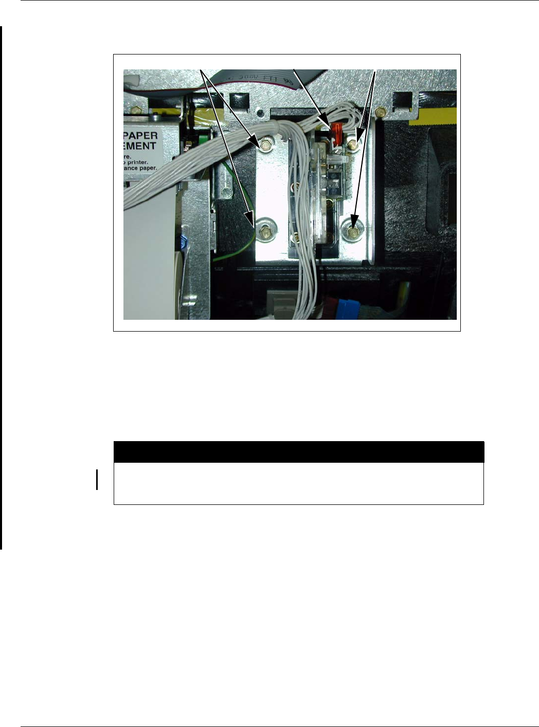
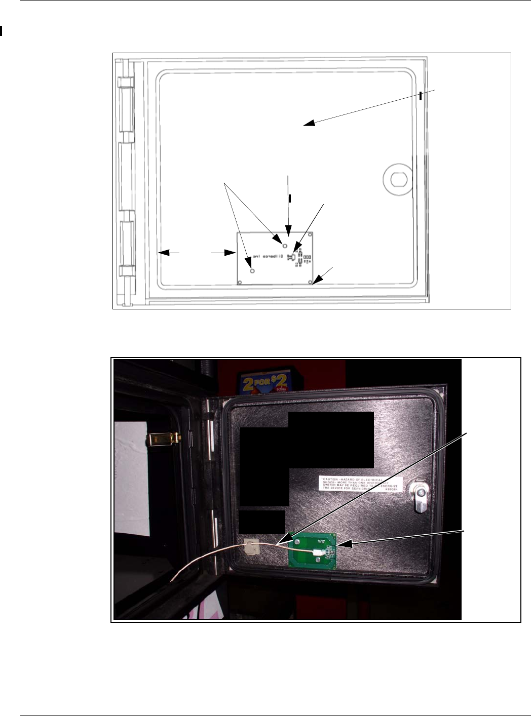
5Disconnect the cable harness or ribbon cable connection from the Card Reader (see Figure 1
on page 12).
6Use a 1/4 inch nut driver to remove the two hex head screws (see Figure 1 on page 12) that
secure the Card Reader bracket (see Figure 1 on page 12) and the Card Reader to the option
door. Dispose of the Card Reader and bracket, unless you want to keep the Card Reader as a
used spare part.
Note: Make a note of the Card Reader’s gasket orientation. This information will be useful
when you install the new Card Reader gasket (M00682B003) and bracket
(M07573B001). Also, ensure that the option door has been cleaned with isopropyl
alcohol and a clean cloth prior to installing the new Card Reader gasket
(M00682B003).
7Remove the old Card Reader gasket from the option door. Use a putty knife, if required.
Installation of the Encrypted Card Reader Retrofit Kit
Page 12 MDE-4635 Encrypted Card Reader Retrofit Kit (M07813K00X) Installation Manual · May 2007
Preliminary
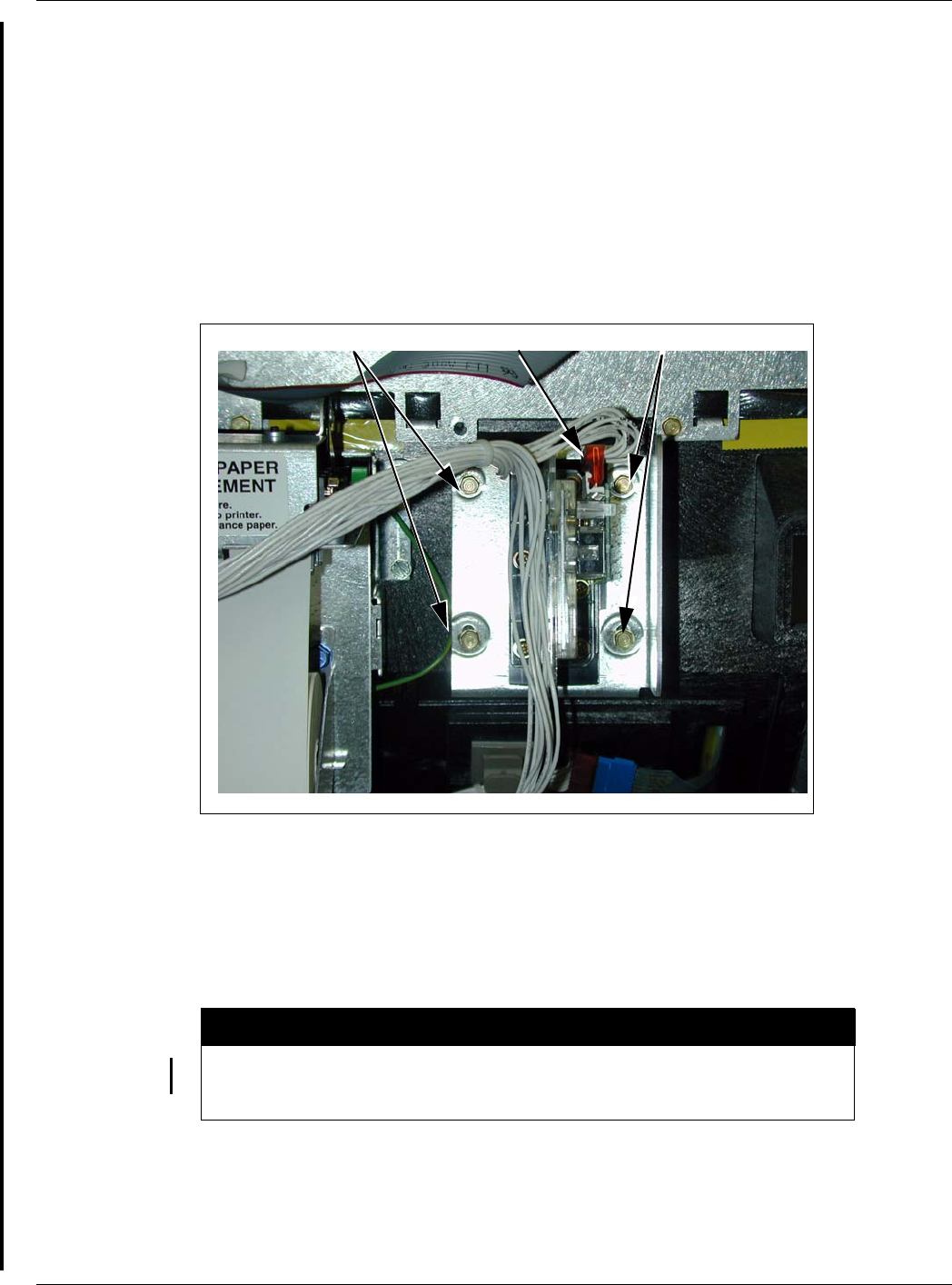
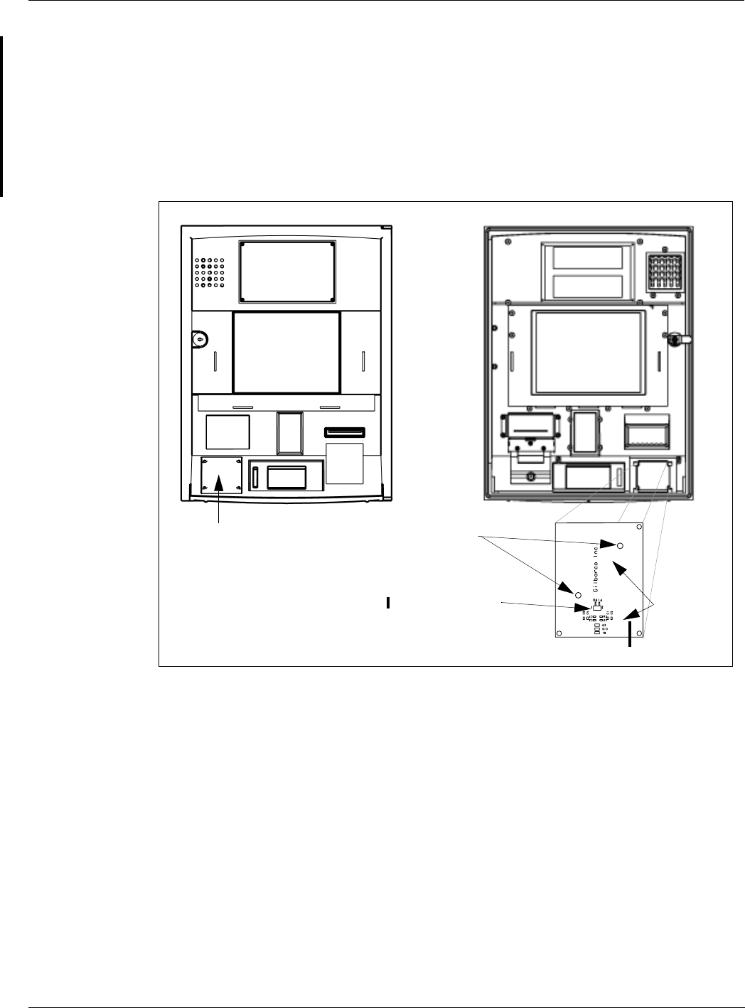
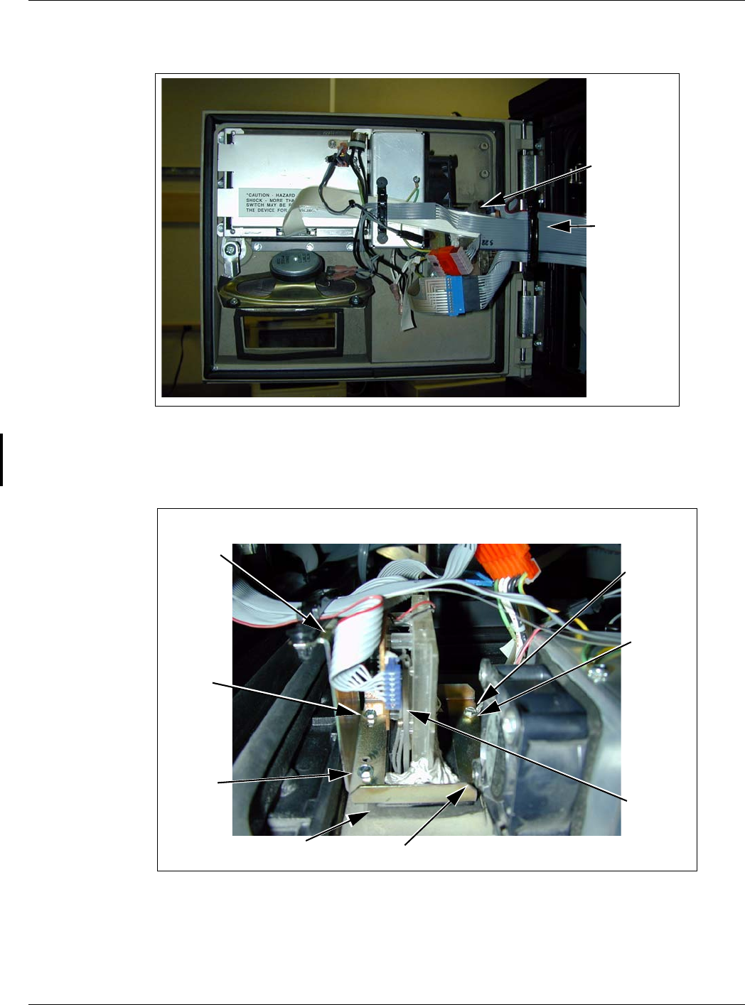
Figure 1: Rear View of the Encore S Main Door with Card Reader
Cable
Harness
Connection
Fastener
Fastener
Installing the Encore Encrypted Card Reader Assembly
To install this assembly, proceed as follows:
1Remove the adhesive backing from the Card Reader gasket (M00682B003) and place the
gasket over the Card Reader opening from the inside of the open main door.
A properly grounded ESD wrist strap must be worn when performing step 2. Failure to
use electrostatic precautions may damage electronic components and void warranty.
CAUTION
2Obtain the Encrypted Card Reader assembly (M07577B001) (Figure 2 on page 13) and
Contactless Smart bracket (M07573B001) (Figure 2 on page 13) from the kit.
MDE-4635 Encrypted Card Reader Retrofit Kit (M07813K00X) Installation Manual · May 2007 Page 13
Installation of the Encrypted Card Reader Retrofit Kit
Preliminary
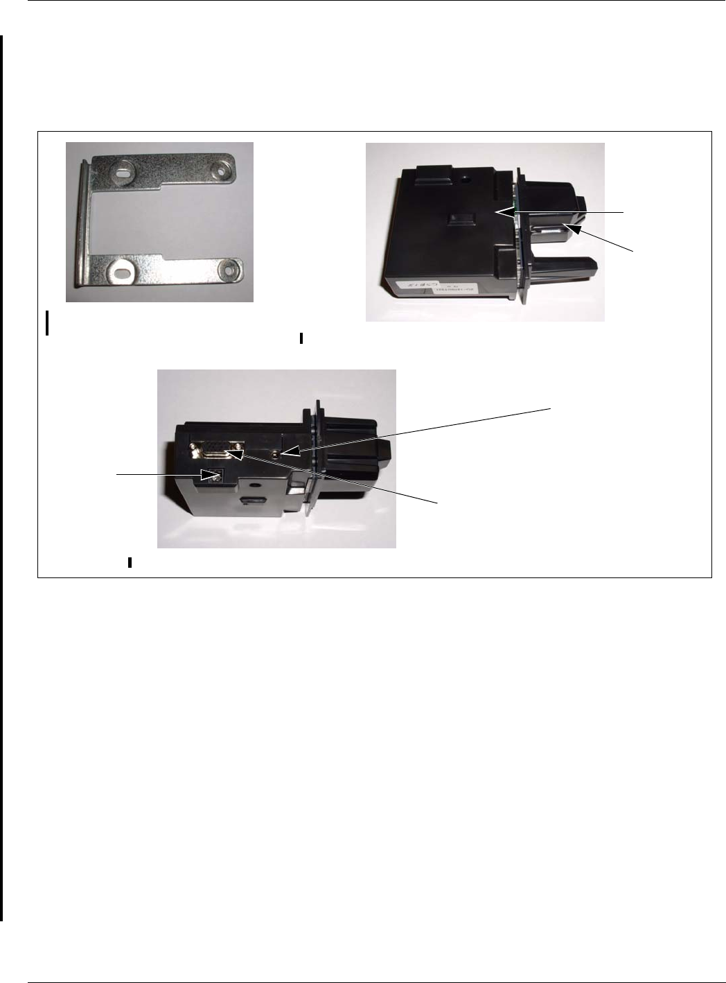
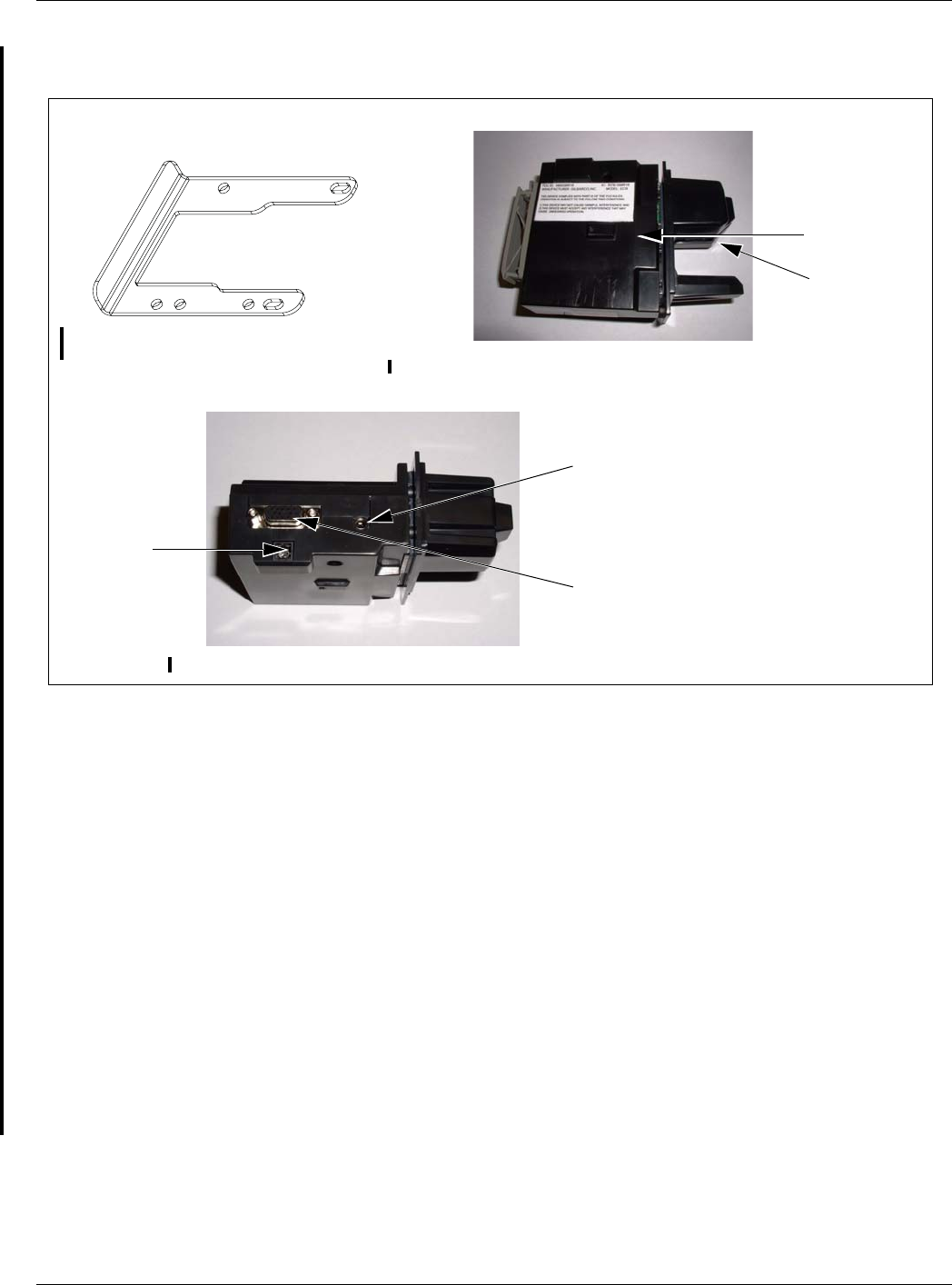
3From the rear of the main door, position the Card Reader and then the Card Reader bracket on
the door such that the Card Reader slot (Figure 2) is positioned on the top.
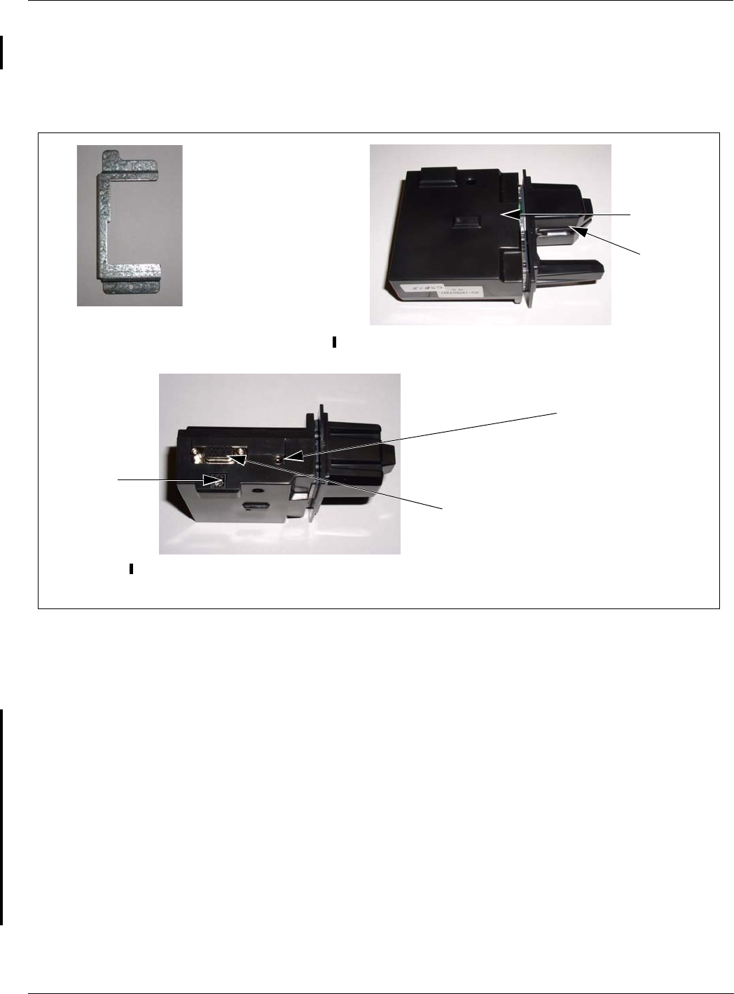
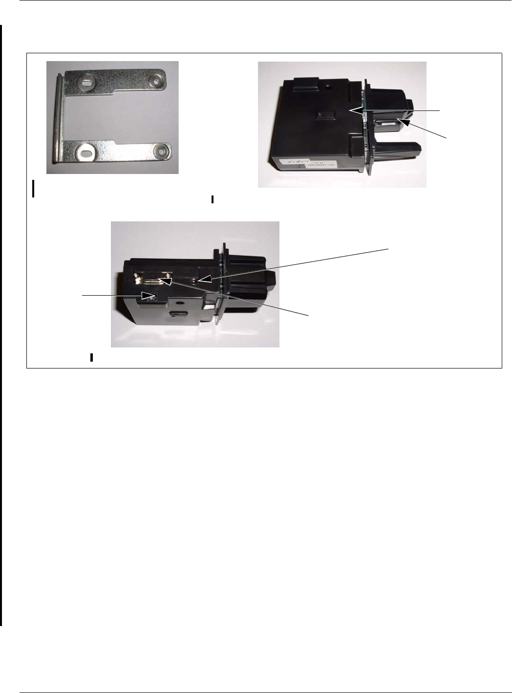
Figure 2: Encrypted Card Reader Assembly and Encore S Bracket
Encore S Encrypted Card
Reader Bracket (M07573B001) Encore S Encrypted Card Reader Assembly (M07577) - Front View
Encore S Encrypted Card Reader Assembly (M07577) - Top View
Printed Circuit
Card (Inside)
Power/Data Connector
Card Reader
Slot
ESD Ground Connection
Antenna
Connector
4Loosely secure the Encrypted Card Reader bracket and Card Reader to the main door using the
two Q11677-24 screws (provided in the kit) in the top and bottom two holes (looking from the
back of the Card Reader).
5Remove the power/data cable from the current Card Reader. Remove the ESD Ground
Connection cable from the current Card Reader (if it has one).
6Align the Card Reader and bracket. Securely tighten the two mounting screws (Q11677-24).
7Reconnect the 7-pin power/data cable (M07702A001) to the 7-pin Power/Data connector
(see Figure 2) on the Card Reader. If the dispenser is equipped with SmartPad™, connect the
SmartPad end of the cable (M07702A001) to the SmartPad CRIND keypad connector. If the
dispenser is not equipped with SmartPad (that is, has a regular CRIND keypad), do not
connect the SmartPad end of the cable (M07702A001), which means that the SmartPad end of
the cable (M07702A001) remains loose and the dispenser’s CRIND keypad connection
remains unaltered.
Installation of the Encrypted Card Reader Retrofit Kit
Page 14 MDE-4635 Encrypted Card Reader Retrofit Kit (M07813K00X) Installation Manual · May 2007
Preliminary
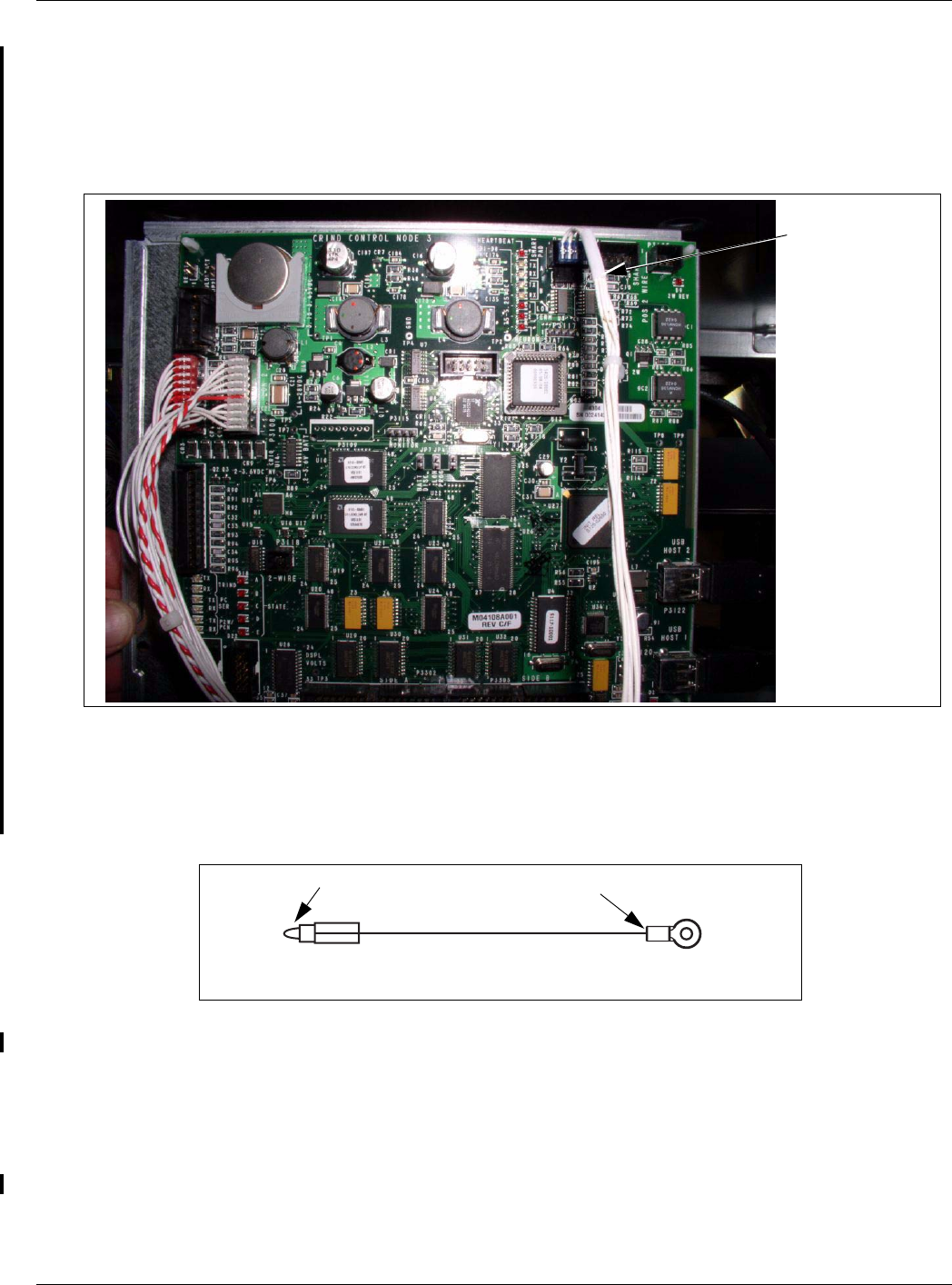
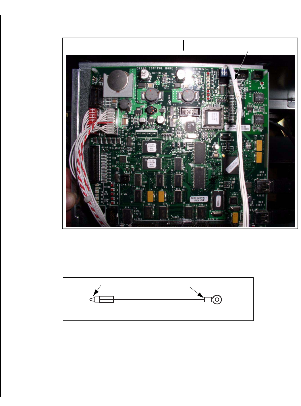
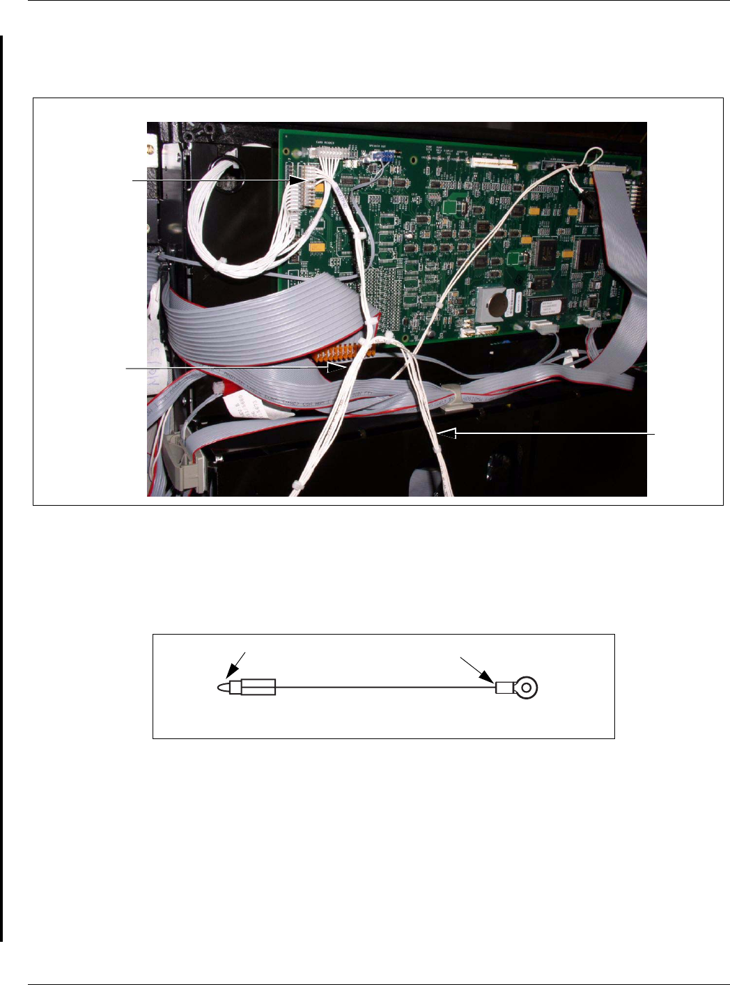
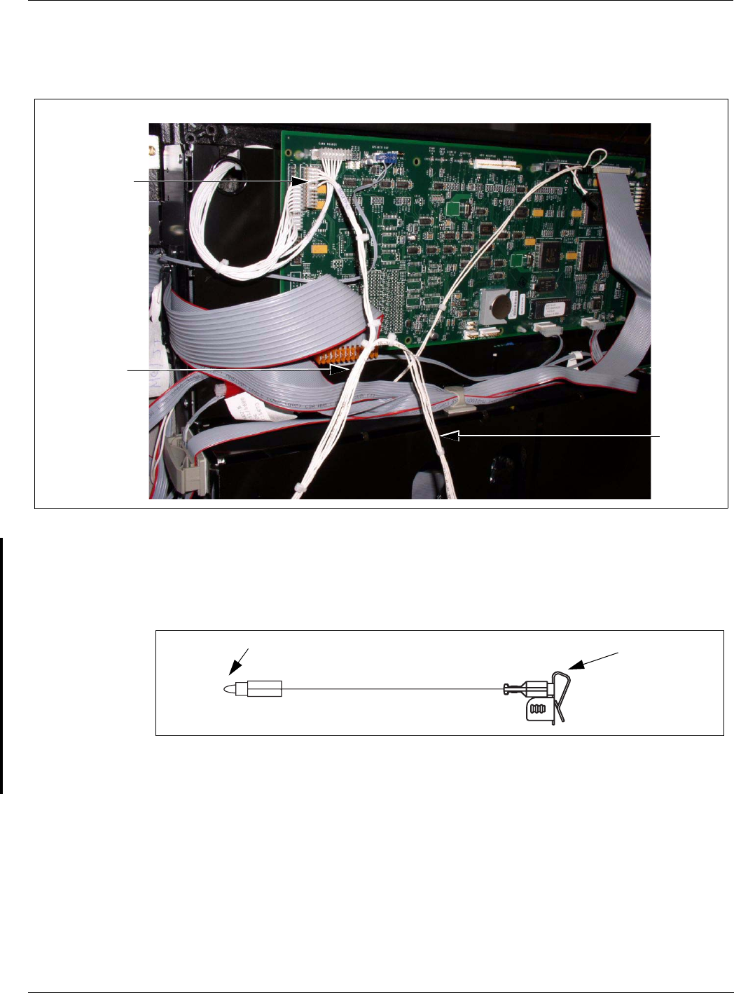
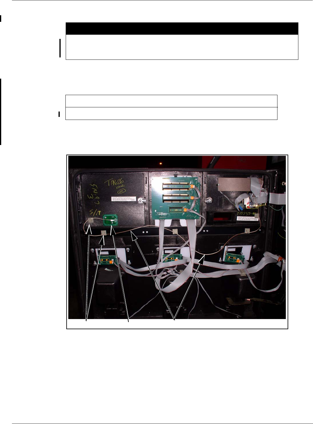
8Connect the J3101/J3102 end to the SmartPad port on the CRIND Control Node Board (see
Figure 3 on page 14).
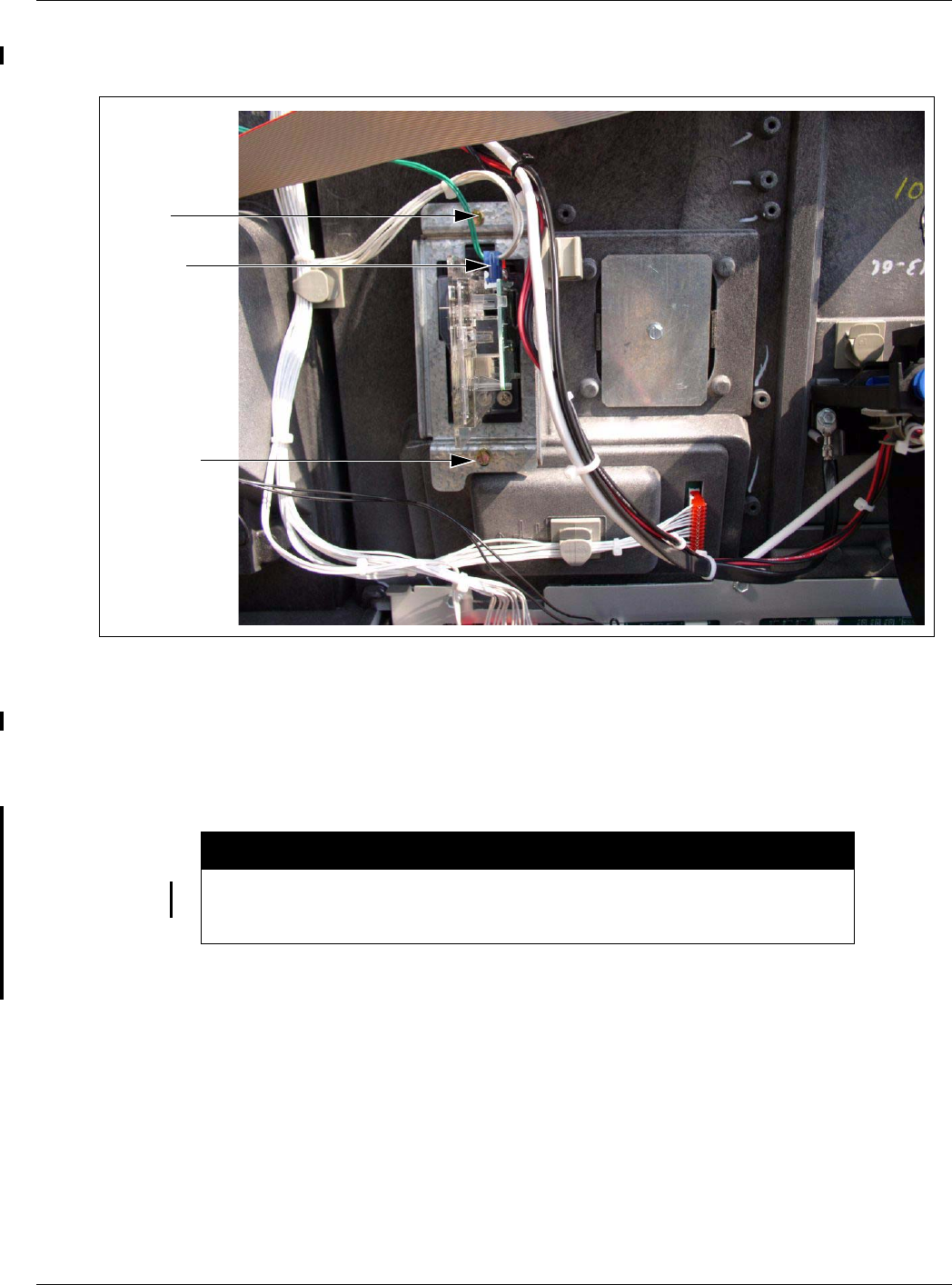
Figure 3: CRIND Control Node Board Showing the Connection of J3101/J3102 End to
the SmartPad Port
Encrypted Card
Reader Data Cable
Connection to CRIND
Control Node Board
9Insert the connector end of the ESD Ground Card cable (M07709A002) (see Figure 4) to the
ESD Ground Connection (see Figure 2 on page 13) on the Card Reader.
Figure 4: Encore/Eclipse ESD Ground Card Cable (M07709A002)
Ring Terminal
Connector
10 Locate the ground ring terminal on the lower portion of the monochrome display mounting
bracket and remove the screw that secures the ground connection. Retain the screw for
reinstallation.
11 Connect the ring terminal (Figure 4) of the ESD Ground Card cable (M07709A002) to the
monochrome display mounting bracket ground connection. Secure the connection with the
screw and lock washer that was removed in step 10.
12 Ensure that all ground cables are secured to the unit with sufficient slack to prevent cable pulls
MDE-4635 Encrypted Card Reader Retrofit Kit (M07813K00X) Installation Manual · May 2007 Page 15
Installation of the Encrypted Card Reader Retrofit Kit
Preliminary
and pinching.
Installing the Antenna PCA
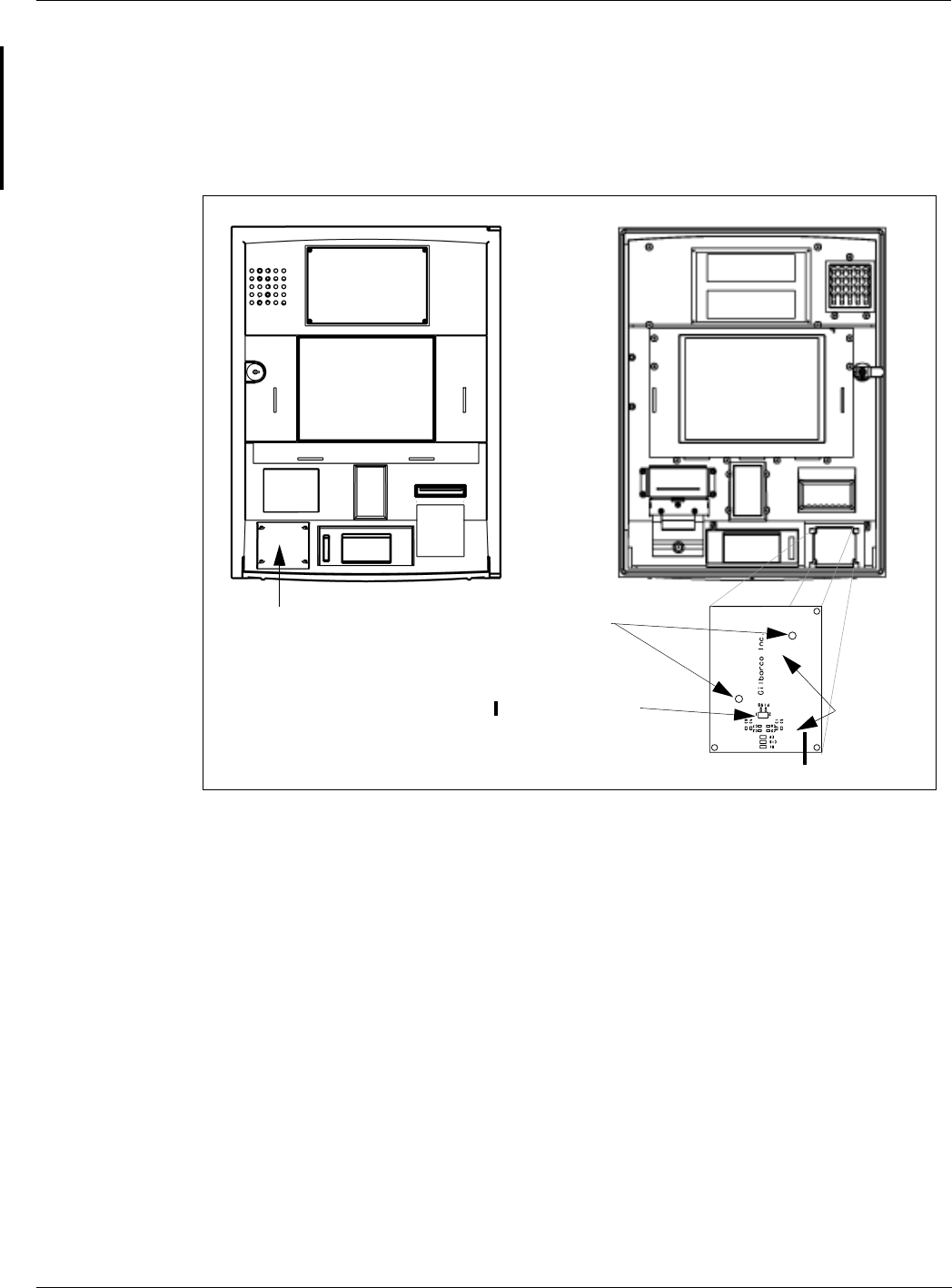
The RF antenna must be located directly behind the area where the MasterCard® PayPass™,
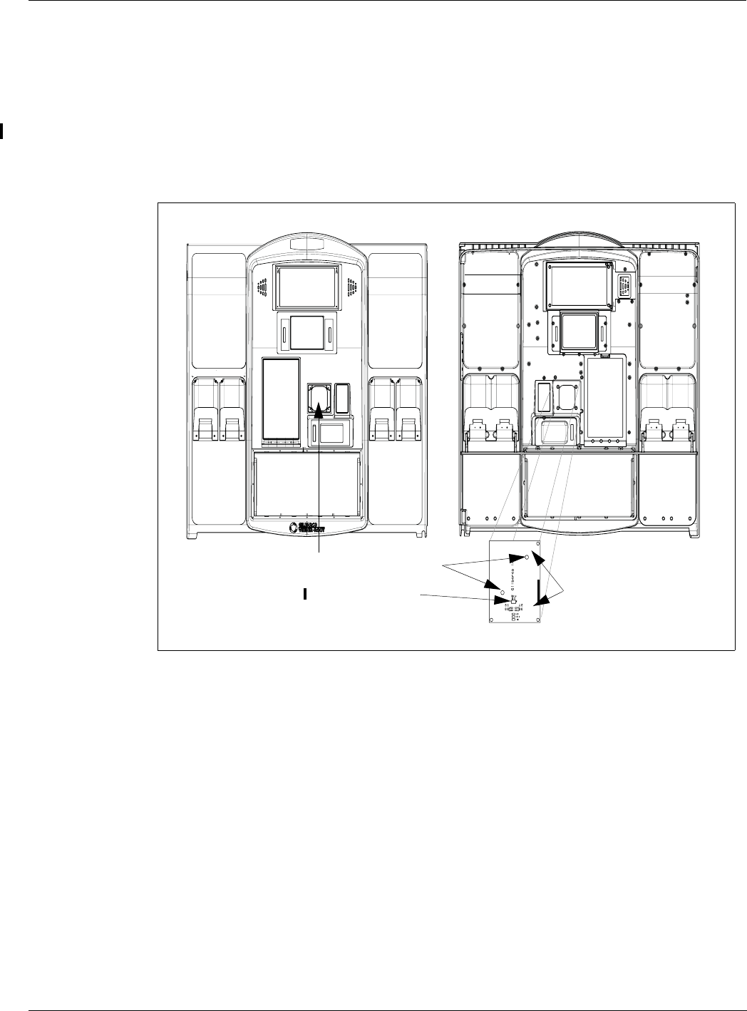
American Express ExpressPaySM and other logo graphics are attached as shown in Figure 5.
Figure 5: Encore S Main Door Showing Antenna PCA Location
PayPass Logo
Location
Front View Rear View
M05170A001 Antenna PCA
2-pin Connector K85492-56 Foam Tape (On the
Backside)
Mounting Holes
Installation of the Encrypted Card Reader Retrofit Kit
Page 16 MDE-4635 Encrypted Card Reader Retrofit Kit (M07813K00X) Installation Manual · May 2007
Preliminary
To install the antenna, proceed as follows:
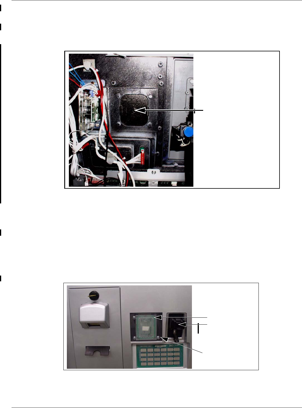
1Remove the small bracket holding in the TRIND blanking panel, and knock out the TRIND
blanking panel (Figure 6) using a hammer.
Figure 6: Encore S Door with the Blanking Panel
Encore S Door with Blanking Panel
2Remove the narrow sealing gasket from the exposed TRIND lens space on the outside of the
door and replace it with the TRIND gasket (M06010B002).
3Locate the M05170A001 Antenna PCA placed on the TRIND CSC Reader Lens
(M05987B002) and place it over the TRIND gasket. Secure the TRIND CSC Reader Lens by
installing and tightening the four screws (M00419B117) (see Figure 7)
4Connect one end of the M07703A001 Antenna Cable to the Card Reader antenna connector of
the Encrypted Card Reader top (Figure 2 on page 13) and the other end of the antenna cable to
the 2-pin connector on the M05170A001 PCA antenna (Figure 5 on page 15).
Figure 7: Antenna PCA on TRIND CSC Reader Lens
Antenna PCA
(M05170A001)
Encrypted Card Reader
(M07577B001)
TRIND Gasket
(M06010B002)
5Repeat steps 1-4 on the other side of the unit.
MDE-4635 Encrypted Card Reader Retrofit Kit (M07813K00X) Installation Manual · May 2007 Page 17
Installation of the Encrypted Card Reader Retrofit Kit
Preliminary
Loading the CRIND Software and Purging Persistent Memory
To load the CRIND software, proceed as follows:
1Remove the CRIND two-wire from the CRIND node. This terminates any interference that
may occur.
2Connect the Download cable to the laptop and the laptop port on the CRIND node.
3Download the appropriate software to the CRIND node.
4Purge the Persistent Memory after the download is complete.
5Reprogram the CRIND IDs and CRIND node.
6Enable the required options (for example, Cash Acceptors, Barcode Scanners, and so on).
7Connect the two-wire back on the CRIND node. Allow the Point of Sale (POS) to download
the CRIND.
8Test the new Card Reader.
RF Read performance will be severely affected by crimps/bends in the antenna cable.
IMPORTANT INFORMATION
Completing the Installation for Encore S Units
To complete the installation, proceed as follows:
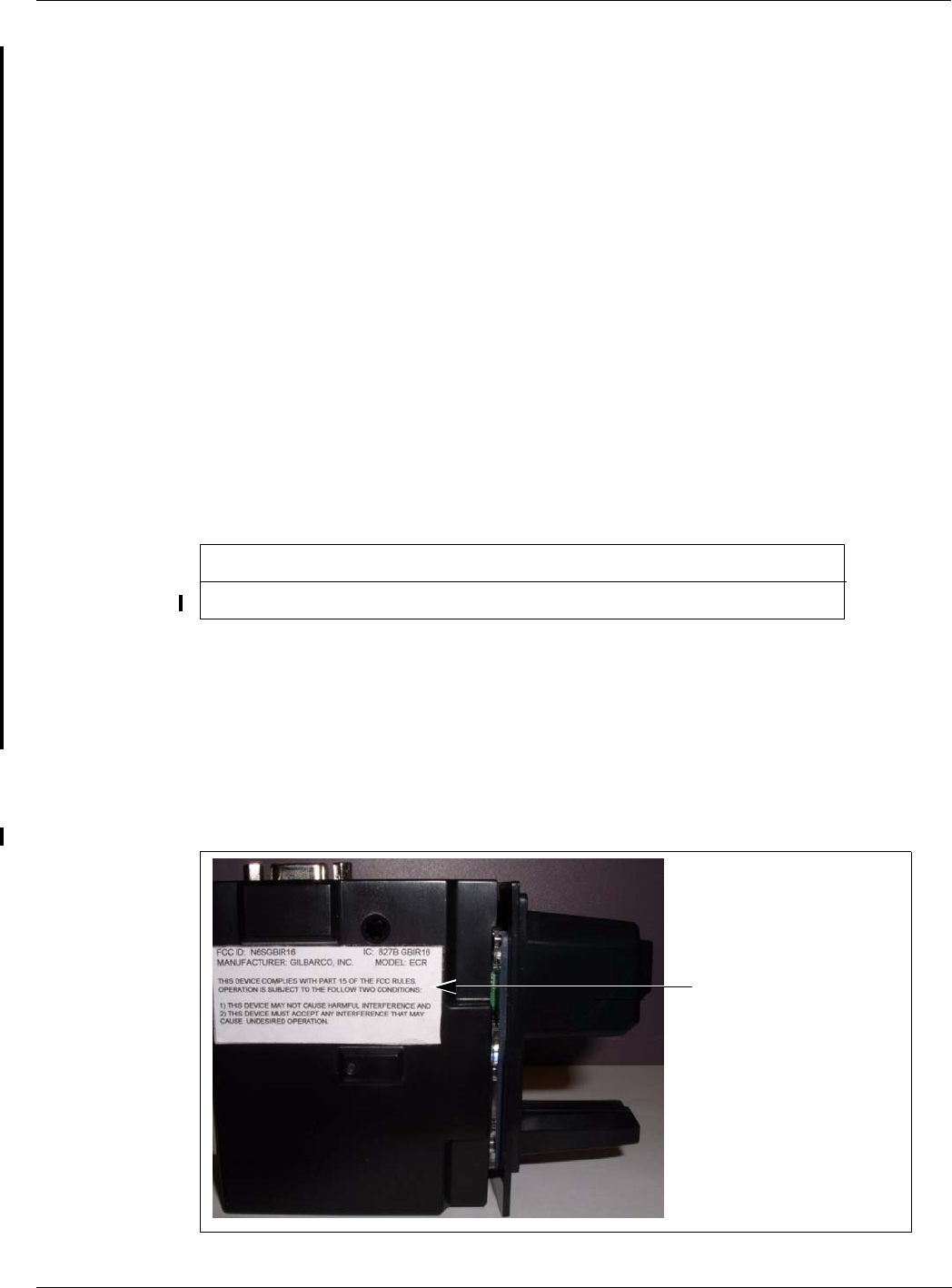
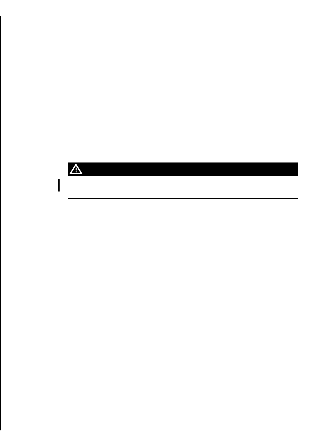
1Install the N23951-11 UL/CA Recognition Decal on the Card Reader bracket as shown in
Figure 8.
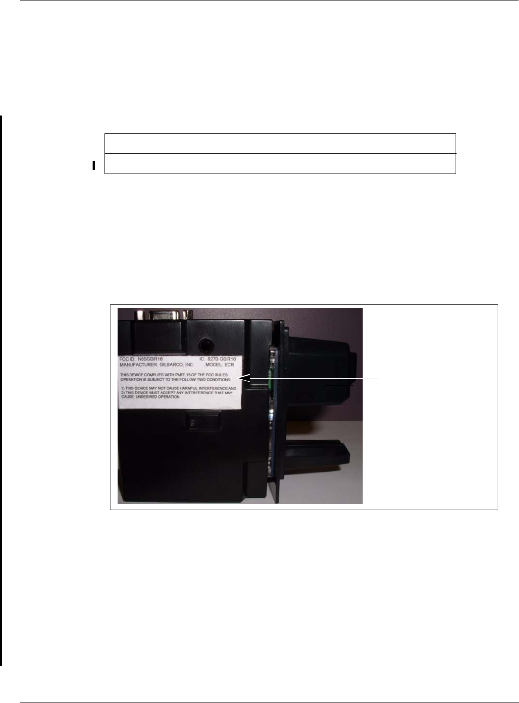
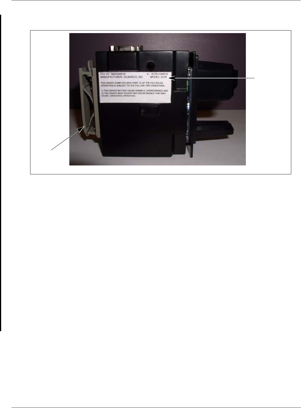
Figure 8: FCC Label on Smart Card Reader (Side)
FCC Label
Installation of the Encrypted Card Reader Retrofit Kit
Page 18 MDE-4635 Encrypted Card Reader Retrofit Kit (M07813K00X) Installation Manual · May 2007
Preliminary
2Close and secure the main doors using the security latch and the main door lock. Reinstall and
lock the lower panel door.
3Restore power to the unit. Refer to MDE-4516 Encore 500 S Owners Manual for details.
4Test the RF Readers by sliding the CRIND diagnostic card (Q12534) through both the readers
with the magnetic strip facing upwards.
5Verify if a valid read was made from the diagnostic card.
6Pass the Encrypted Card Reader test card in front of the RF antenna (flat side towards the
antenna).
7Verify if a valid read was made from the test card. The CRIND beeper will emit an audible
beep upon performing a successful read.
Note: The test card should be read from a minimum distance of 1 inch when presented parallel
to the bezel surface.
8Apply the appropriate graphic logos. These are order entry items. Refer MDE-4625 Graphics
Panel Application and Repair for graphic application instructions.
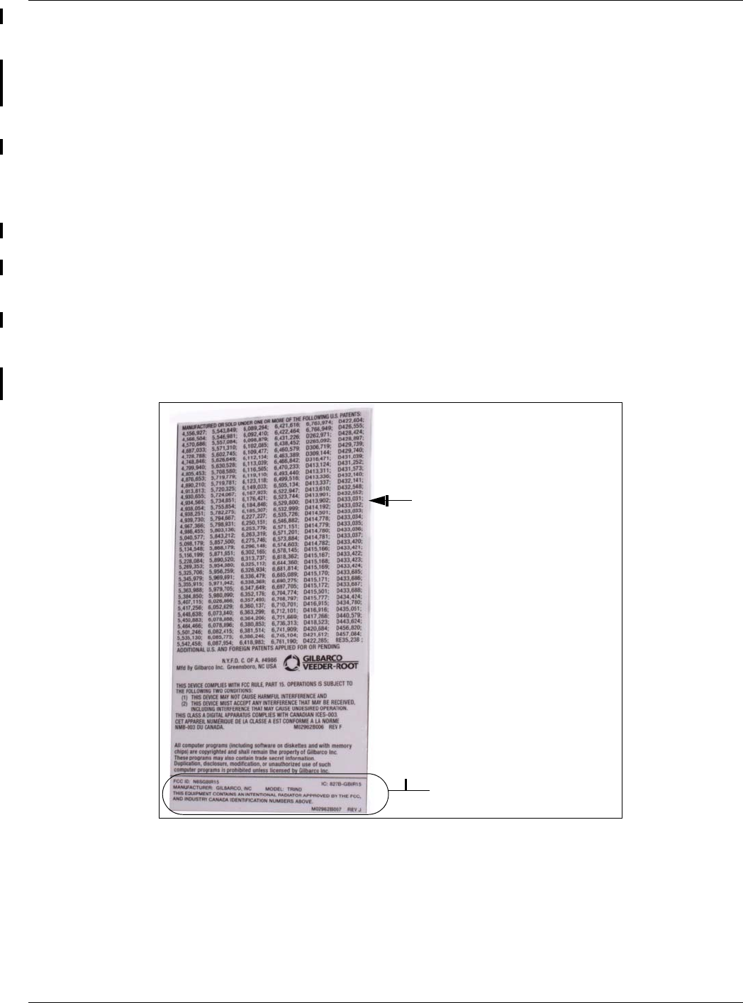
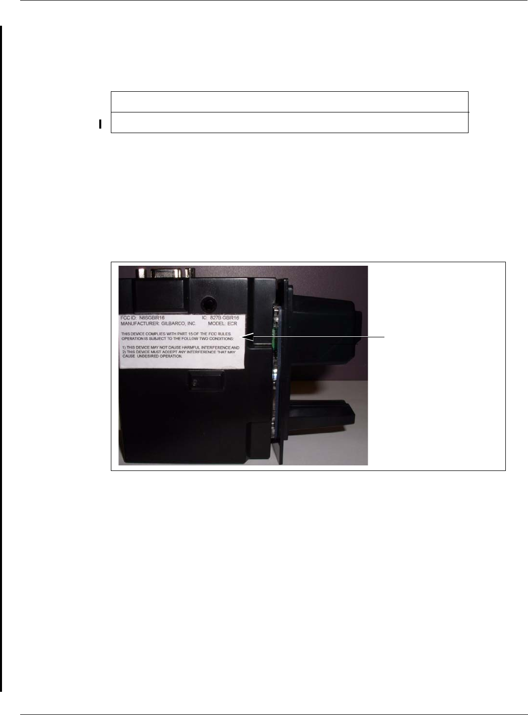
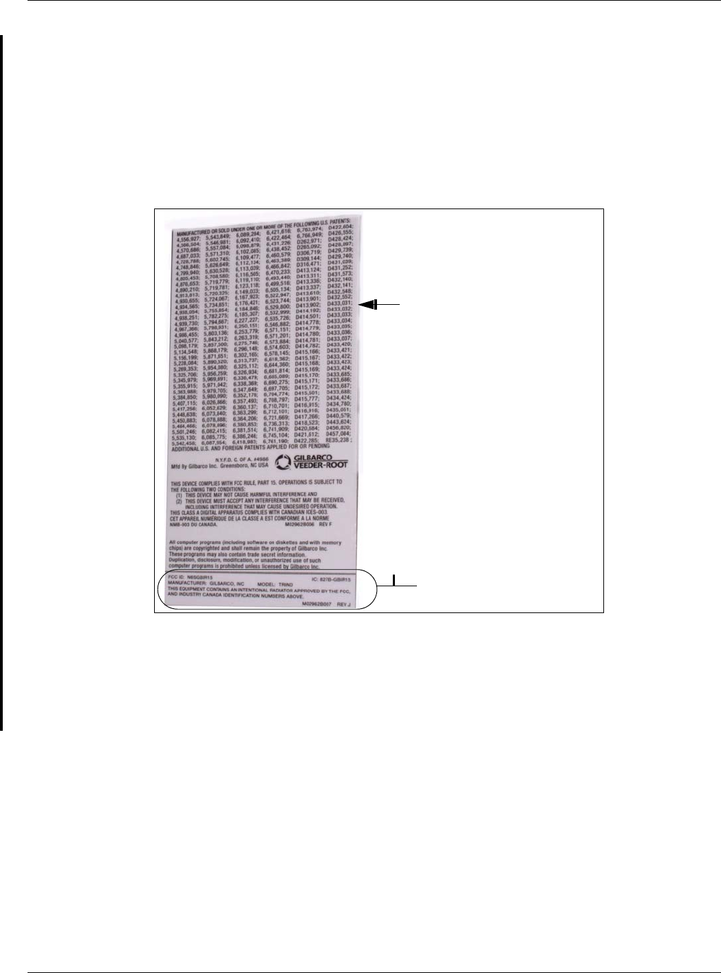
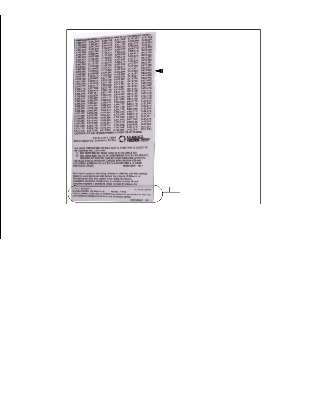
9Obtain the FCC Decal (M02962B009) from the kit and install it under the patent label.
TRIND FCC Label Nameplate
(M02962B009)
Patent Label

MDE-4635 Encrypted Card Reader Retrofit Kit (M07813K00X) Installation Manual · May 2007 Page 19
Installation of the Encrypted Card Reader Retrofit Kit
Preliminary
Installing the M07813K002 Kit in an Encore S Unit (without Contactless Card
Reader Option)
The installation instructions for the M07813K002 kit are similar to the installation instructions
for the M07813K001 kit.
To install the M07813K002 Kit, proceed as follows:
1Remove the existing Card Reader. Refer to “Removing the Existing Card Reader” on page 11
for instructions.
2Install the Encore Encrypted Card Reader assembly. Refer to “Installing the Encore Encrypted
Card Reader Assembly” on page 12 for instructions.
3Load the CRIND software and purge the persistent memory. Refer to “Loading the CRIND
Software and Purging Persistent Memory” on page 17 for instructions.
4Complete the installation by referring to “Completing the Installation for Encore S Units” on
page 17.
Note: Do not perform steps 4 to 7.
5Verify that the Card Reader will read a card.
Installing the M07813K003 Kit in an Encore 500 Unit (with Contactless Card
Reader Option)
When you install an Encrypted Card Reader kit, the existing Card Reader must be removed
and replaced with the Encrypted Card Reader.
Removing the Existing Card Reader
To remove the existing Card Reader, proceed as follows:
Note: Read all instructions before beginning and observe all safety precautions.
1Obtain an approval from the store manager or responsible personnel to remove the unit from
service.
2Remove AC power to the unit using the station circuit breaker. Refer to MDE-3893 Encore/
Eclipse Owners Manual for details.
3Locate the main door, insert the key, and open the door.
4Repeat step 2 for Side 2 of the unit.
5Disconnect the cable harness or ribbon cable connection from the Card Reader (see Figure 9
on page 20).
Installation of the Encrypted Card Reader Retrofit Kit
Page 20 MDE-4635 Encrypted Card Reader Retrofit Kit (M07813K00X) Installation Manual · May 2007
Preliminary
6Use a 1/4 inch nut driver to remove the four hex head screws (see Figure 9) that secure the
Card Reader bracket (see Figure 9) and the Card Reader to the option door. Dispose of the
Card Reader and bracket, unless you want to keep the Card Reader as a used spare part.
Note: Make a note of the Card Reader’s gasket orientation. This information will be useful
when you install the new Card Reader gasket (M00682B001) and bracket
(M07574B001). Also, ensure that the option door has been cleaned with isopropyl
alcohol and a clean cloth prior to installing the new Card Reader gasket
(M00682B001).
7Remove the old Card Reader gasket from the option door. Use a putty knife, if required.
Figure 9: Rear View of Encore 500 Main Door with Card Reader
Cable Harness Connection Fasteners
Fasteners
Installing the Encore Encrypted Card Reader Assembly
To install this assembly, proceed as follows:
1Remove the adhesive backing from the Card Reader gasket (M00682B001) and place the
gasket over the Card Reader opening from the inside of the open main door.
A properly grounded ESD wrist strap must be worn when performing step 2. Failure to
use electrostatic precautions may damage electronic components and void warranty.
CAUTION
2Obtain the Encrypted Card Reader assembly (M07577B001) (Figure 10 on page 21) and
contactless smart bracket (M07574B001) (Figure 10 on page 21) from the kit.
3From the rear of the main door, position the Card Reader and then the Card Reader bracket in
the door such that the Card Reader slot (Figure 10 on page 21) is positioned on the top.
MDE-4635 Encrypted Card Reader Retrofit Kit (M07813K00X) Installation Manual · May 2007 Page 21
Installation of the Encrypted Card Reader Retrofit Kit
Preliminary
Figure 10: Encrypted Card Reader Assembly and Encore 500 Bracket
Encore 500 Encrypted Card
Reader Bracket (M07574B001) Encore 500 Encrypted Card Reader Assembly (M07577) - Front View
Encore 500 Encrypted Card Reader Assembly (M07577) - Top View
Printed Circuit
Card (Inside)
Power/Data Connector
Card Reader
Slot
ESD Ground Connection
Antenna
Connector
4Loosely secure the Encrypted Card Reader bracket and Card Reader to the main door using the
four Q11677-24 screws (provided in the kit) in the Side 4 holes (looking from the back of the
Card Reader).
5Remove the power/data cable from the current Card Reader. Remove the ESD Ground
Connection cable from the current Card Reader (if it has one).
6Align the Card Reader and bracket. Securely tighten the four mounting screws (Q11677-24).
7Reconnect the 7-pin power/data cable (M07702A003) to the 7-pin Power/Data connector
(see Figure 10) on the Card Reader. If the dispenser is equipped with SmartPad, connect the
SmartPad end of the cable (M07702A003) to the SmartPad CRIND keypad connector. If the
dispenser is not equipped with SmartPad (that is, has a regular CRIND keypad), do not
connect the SmartPad end of the cable (M07702A003), which means that the SmartPad end of
the cable (M07702A003) remains loose and the dispenser’s CRIND keypad connection
remains unaltered.
8Connect the J3101/J3102 end to the SmartPad port on the CRIND Control Node Board (see
Figure 11 on page 22).
Installation of the Encrypted Card Reader Retrofit Kit
Page 22 MDE-4635 Encrypted Card Reader Retrofit Kit (M07813K00X) Installation Manual · May 2007
Preliminary
Figure 11: CRIND Control Node Board Showing the Connection of J3101/J3102 End to
the SmartPad Port
Encrypted Card Reader Data Cable Connection
to CRIND Control Node Board
9Insert the connector end of the ESD Ground Card cable (M07709A001) (see Figure 12) to the
ESD Ground Connection (see Figure 10 on page 21) on the Card Reader.
Figure 12: Encore/Eclipse ESD Ground Card Cable (M07709A001)
Ring Terminal
Connector
10 Locate the ground ring terminal on the lower portion of the monochrome display mounting
bracket and remove the screw that secures the ground connection. Retain the screw for
reinstallation.
11 Connect the ring terminal (Figure 12) of the ESD Ground Card cable (M07709A001) to the
monochrome display mounting bracket ground connection. Secure the connection with the
screw and lock washer that was removed in step 10.
12 Ensure that all ground cables are secured to the unit with sufficient slack to prevent cable pulls
MDE-4635 Encrypted Card Reader Retrofit Kit (M07813K00X) Installation Manual · May 2007 Page 23
Installation of the Encrypted Card Reader Retrofit Kit
Preliminary
and pinching.
Installing the Antenna PCA
The RF antenna must be located directly behind the area where the MasterCard PayPass,
American Express ExpressPay and other logo graphics are attached as shown in Figure 13.
Figure 13: Encore 500 Main Door Showing Antenna PCA Location
M05170A001 Antenna PCA
PayPass Logo
Location
Front View Rear View
Mounting Holes
2-pin Connector K85492-56
Foam Tape
(On the
Backside)
Installation of the Encrypted Card Reader Retrofit Kit
Page 24 MDE-4635 Encrypted Card Reader Retrofit Kit (M07813K00X) Installation Manual · May 2007
Preliminary
To install the antenna, proceed as follows:
1Locate the area where the antenna PCA will be mounted.
2Using isopropyl alcohol, clean the mounting surface.
3Locate the M05170A001 Antenna PCA and the two 2 inch strips of K85492-56 foam tape in
the kit. Install the two strips of foam tape to the antenna’s rear surface (non-component side of
antenna PCA). These strips may already be installed on the antenna (PCB).
4Peel the protective cover from the foam adhesive strips on the antenna and orient the antenna
as shown in Figure 13 on page 23 and attach it to the main door surface by pressing the foam
tape firmly against the main door.
5Using two Q11657-290 screws (part of the kit), secure the antenna in place by inserting the
screws in the mounting holes (Figure 13 on page 23) and turning the self-tapping screws into
the main door.
When drilling on the island, always use a non-sparking manual (hand) drill. Else, remove
the door and move to a safe place to drill.
CAUTION
Note: Since there are no pilot holes in the plastic for these antenna mounting screws,
significant force is required to get the screws to penetrate the plastic. If problems are
encountered, it is acceptable to drill a pilot hole of 1/8 inch diameter or less, by a
maximum depth of 3/16 inch to start each screw. Do not completely drill through the
plastic.
6Connect one end of the M07703A001 Antenna Cable to the Card Reader antenna connector of
the Encrypted Card Reader top (Figure 10 on page 21) and the other end of the antenna cable
to the 2-pin connector on the M05170A001 PCA antenna (Figure 13 on page 23).
7Repeat steps 1 to 6 on the other side of the unit.
Loading the CRIND Software and Purging Persistent Memory
To load the CRIND software, proceed as follows:
1Remove the CRIND two-wire from the CRIND node. This terminates any interference that
may occur.
2Connect the Download cable to the laptop and the laptop port on the CRIND node.
3Download the appropriate software to the CRIND node.
4Purge the Persistent Memory after the download is complete.
5Reprogram the CRIND IDs and CRIND node.
6Enable the required options (for example, Cash Acceptors, Barcode Scanners, and so on).
MDE-4635 Encrypted Card Reader Retrofit Kit (M07813K00X) Installation Manual · May 2007 Page 25
Installation of the Encrypted Card Reader Retrofit Kit
Preliminary
7Connect the two-wire back on the CRIND node. Allow the Point of Sale (POS) to download
the CRIND.
8Test the new Card Reader.
RF Read performance will be severely affected by crimps/bends in the antenna cable.
IMPORTANT INFORMATION
Completing Installation for Encore 500 Units
To complete the installation, proceed as follows:
1Install the N23951-11 UL/CA Recognition Decal on the back of the Card Reader as shown in
Figure 14.
Figure 14: FCC Label on Smart Card Reader (Side)
FCC Label
2Close and secure the main doors using the security latch and the main door lock. Reinstall and
lock the lower panel door.
3Restore power to the unit. Refer to MDE-4516 Encore 500 S Owners Manual for details.
4Test the RF Readers by sliding the CRIND diagnostic card (Q12534) through both the readers
with the magnetic strip facing upwards.
5Verify if a valid read was made from the diagnostic card.
6Pass the Encrypted Card Reader test card in front of the RF antenna (flat side towards the
antenna).
7Verify if a valid read was made from the test card. The CRIND beeper will emit an audible
beep upon performing a successful read.
Note: The test card should be read from a minimum distance of 1 inch when presented parallel
to the bezel surface.
Installation of the Encrypted Card Reader Retrofit Kit
Page 26 MDE-4635 Encrypted Card Reader Retrofit Kit (M07813K00X) Installation Manual · May 2007
Preliminary
8Apply the appropriate graphic logos. These are order entry items. Refer MDE-4625 Graphics
Panel Application and Repair for graphic application instructions.
9Obtain the FCC Decal (M02962B009) from the kit and install it under the patent label.
TRIND FCC Label Nameplate
(M02962B009)
Patent Label
Installing the M07813K004 Kit in an Encore 500 Unit (without Contactless
Card Reader Option)
The installation instructions for the M07813K004 kit are similar to the installation instructions
for the M07813K003 kit.
To install the M07813K004 Kit, proceed as follows:
1Remove the existing Card Reader. Refer to “Removing the Existing Card Reader” on page 19
for instructions.
2Install the Encore Encrypted Card Reader Assembly. Refer to “Installing the Encore
Encrypted Card Reader Assembly” on page 20 for instructions.
3Load the CRIND software and purge the persistent memory. Refer to “Loading the CRIND
Software and Purging Persistent Memory” on page 24 for instructions.
4Complete the installation by referring to “Completing Installation for Encore 500 Units” on
page 25.
Note: Do not perform steps 4 to 7.
5Verify that the Card Reader will read a card.

MDE-4635 Encrypted Card Reader Retrofit Kit (M07813K00X) Installation Manual · May 2007 Page 27
Installation of the Encrypted Card Reader Retrofit Kit
Preliminary
Installing the M07813K005 Kit in an Encore 300 Unit (with Contactless Card
Reader Option)
When you install an Encrypted Card Reader kit, the existing Card Reader must be removed
and replaced with the Encrypted Card Reader.
Removing the Existing Card Reader
To remove the existing Card Reader, proceed as follows:
Note: Read all instructions before beginning and observe all safety precautions.
1Obtain an approval from the store manager or responsible personnel to remove the unit from
service.
2Remove AC power to the unit using the station circuit breaker. Refer to MDE-3893 Encore/
Eclipse Owners Manual for details.
3Locate the main door, insert the key, and open the door.
4Repeat step 2 for Side 2 of the unit.
5Disconnect the cable harness or ribbon cable connection from the Card Reader (see Figure 15
on page 28).
6Use a 1/4 inch nut driver to remove the four hex head screws (see Figure 15 on page 28) that
secure the Card Reader bracket (see Figure 15 on page 28) and the Card Reader to the option
door. Dispose of the Card Reader and bracket, unless you want to keep the Card Reader as a
used spare part.
Note: Make a note of the Card Reader’s gasket orientation. This information will be useful
when you install the new Card Reader gasket (M00682B001) and bracket
(M07574B001). Also, ensure that the option door has been cleaned with isopropyl
alcohol and a clean cloth prior to installing the new Card Reader gasket
(M00682B001).
7Remove the old Card Reader gasket from the option door. Use a putty knife, if required.
Installation of the Encrypted Card Reader Retrofit Kit
Page 28 MDE-4635 Encrypted Card Reader Retrofit Kit (M07813K00X) Installation Manual · May 2007
Preliminary
Figure 15: Rear View of Encore 300 Main Door with Card Reader
Cable Harness Connection Fasteners
Fasteners
Installing the Encore Encrypted Card Reader Assembly
To install this assembly, proceed as follows:
1Remove the adhesive backing from the Card Reader gasket (M00682B001) and place the
gasket over the Card Reader opening from the inside of the open main door.
A properly grounded ESD wrist strap must be worn when performing step 2. Failure to
use electrostatic precautions may damage electronic components and void warranty.
CAUTION
2Obtain the Encrypted Card Reader assembly (M07577B001) (Figure 16 on page 29) and
contactless smart bracket (M07574B001) (Figure 16 on page 29) from the kit.
MDE-4635 Encrypted Card Reader Retrofit Kit (M07813K00X) Installation Manual · May 2007 Page 29
Installation of the Encrypted Card Reader Retrofit Kit
Preliminary
3From the rear of the main door, position the Card Reader and then the Card Reader bracket in
the door such that the Card Reader slot (Figure 16) is positioned on the top.
Figure 16: Encrypted Card Reader Assembly and Encore 300 Bracket
Encore 300 Encrypted Card
Reader Bracket (M07574B001) Encore 300 Encrypted Card Reader Assembly (M07577) - Front View
Encore 300 Encrypted Card Reader Assembly (M07577) - Top View
Printed Circuit
Card (Inside)
Power/Data Connector
Card Reader
Slot
ESD Ground Connection
Antenna
Connector
4Loosely secure the Encrypted Card Reader bracket and Card Reader to the main door using the
four screws (Q11677-24) provided in the kit, to the four holes (looking from the back of the
Card Reader).
5Remove the power/data cable from the current Card Reader. Remove the ESD Ground
Connection cable from the current Card Reader (if it has one).
6Align the Card Reader and bracket. Securely tighten the four mounting screws (Q11677-24).
7Reconnect the 7-pin power/data cable (M07702A002) to the 7-pin Power/Data connector (see
Figure 16) on the Card Reader. If the dispenser is equipped with SmartPad, connect the
SmartPad end of the cable (M07702A002) to the SmartPad CRIND keypad connector. If the
dispenser is not equipped with SmartPad (that is, has a regular CRIND keypad), do not
connect the SmartPad end of the cable (M07702A002), which means that the SmartPad end of
the cable (M07702A002) remains loose and the dispenser’s CRIND keypad connection
remains unaltered.
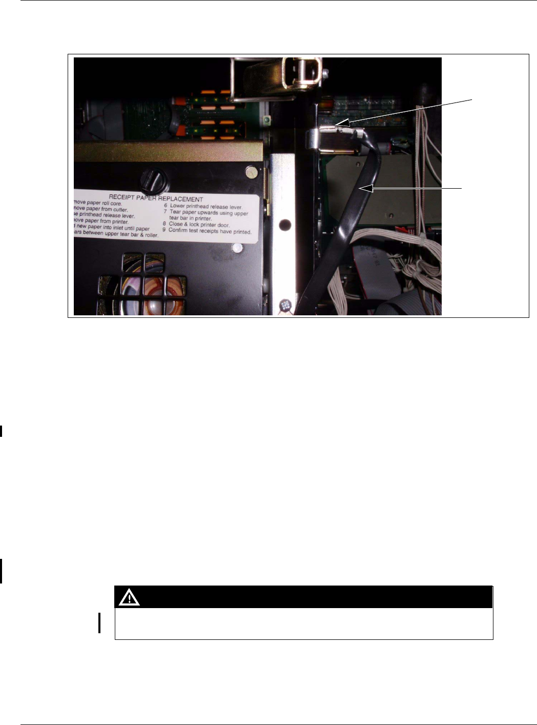
8Connect the J282 end of the M07702A002 cable to the SmartPad port on the CRIND Control
Logic Board (see Figure 17 on page 30) - either M03651 (current production) or T17764.
Installation of the Encrypted Card Reader Retrofit Kit
Page 30 MDE-4635 Encrypted Card Reader Retrofit Kit (M07813K00X) Installation Manual · May 2007
Preliminary
Figure 17: CRIND Control Logic Board (M03651) Showing the Connection of J282 End
to the SmartPad Port
SmartPad Cable
To Card Reader
To
SmartPad
9Insert the connector end of the ESD Ground Card cable (M07709A001) (see Figure 18) to the
ESD Ground Connection (see Figure 16 on page 29) on the Card Reader.
Figure 18: Encore/Eclipse ESD Ground Card Cable (M07709A001)
Ring Terminal
Connector
10 Locate the ground ring terminal on the lower portion of the monochrome display mounting
bracket and remove the screw that secures the ground connection. Retain the screw for
reinstallation.
11 Connect the ring terminal (Figure 18) of the ESD Ground Card cable (M07709A001) to the
monochrome display mounting bracket ground connection. Secure the connection with the
screw and lock washer that was removed in step 10.
12 Ensure that all ground cables are secured to the unit with sufficient slack to prevent cable pulls
and pinching.
MDE-4635 Encrypted Card Reader Retrofit Kit (M07813K00X) Installation Manual · May 2007 Page 31
Installation of the Encrypted Card Reader Retrofit Kit
Preliminary
Installing the Antenna PCA
The RF antenna must be located directly behind the area where the MasterCard PayPass,
American Express ExpressPay and other logo graphics are attached as shown in Figure 19.
Figure 19: Encore 300 Main Door Showing Antenna PCA Location
M05170A001 Antenna PCA
PayPass Logo
Location
Front View Rear View
Mounting Holes
2-pin Connector K85492-56
Foam Tape
(On the
Backside)
Installation of the Encrypted Card Reader Retrofit Kit
Page 32 MDE-4635 Encrypted Card Reader Retrofit Kit (M07813K00X) Installation Manual · May 2007
Preliminary
To install the antenna, proceed as follows:
1Locate the area where the antenna PCA will be mounted.
2Using isopropyl alcohol, clean the mounting surface.
3Locate the M05170A001 Antenna PCA and the two 2 inch strips of K85492-56 foam tape in
the kit. Install the two strips of foam tape to the antenna’s rear surface (non-component side of
antenna PCA). These strips may already be installed on the antenna (PCB).
4Peel the protective cover from the foam adhesive strips on the antenna and orient the antenna
as shown in Figure 19 on page 31 and attach it to the main door surface by pressing the foam
tape firmly against the main door.
5Using two Q11657-290 screws (part of the kit), secure the antenna in place by inserting the
screws in the mounting holes (Figure 19 on page 31) and turning the self-tapping screws into
the main door.
When drilling on the island, always use a non-sparking manual (hand) drill. Else, remove
the door and move to a safe place to drill.
CAUTION
Note: Since there are no pilot holes in the plastic for these antenna mounting screws,
significant force is required to get the screws to penetrate the plastic. If problems are
encountered, it is acceptable to drill a pilot hole of 1/8 inch diameter or less, by a
maximum depth of 3/16 inch to start each screw. Do not completely drill through the
plastic.
6Connect one end of the M07703A001 Antenna Cable to the Card Reader antenna connector of
the Encrypted Card Reader top (Figure 16 on page 29) and the other end of the antenna cable
to the 2-pin connector on the M05170A001 PCA antenna (Figure 19 on page 31).
7Repeat steps 1-6 on the other side of the unit.
Cold-starting the CRIND Devices using the M03651A001, A002 and
T17764 CRIND Logic Boards
1Locate the CRIND Logic Board (s) on side 1 and side 2 main doors.
2Use a chip remover to remove the current firmware chip located at U7 (located directly above
connector P266).
3On side 1 of the unit, install the required firmware chip at U7 on the CRIND Logic Board.
Repeat the procedure on the other side of the unit.
4Install a jump jack on JP-19 (cold-start) on both side 1 and side 2, if you are using the
M03651A001 or A002 CRIND Logic Board. If you are using the T17764 CRIND Logic
Board install a jump jack on JP-11 (cold-start) on the CRIND Logic Boards on both sides of
the unit.
MDE-4635 Encrypted Card Reader Retrofit Kit (M07813K00X) Installation Manual · May 2007 Page 33
Installation of the Encrypted Card Reader Retrofit Kit
Preliminary
5Power-up the dispenser. At this point, both CRIND devices will cold-start and start a
download sequence. Once the download sequence starts, you can remove the jump jacks from
JP-19 or JP-11 (as applicable) on both the CRIND Logic Boards. If you wait too long, a
message will be displayed on the CRIND display prompting you to remove the jump jacks.
Once the CRIND devices have completed the download process, they will automatically start
communicating with the POS.
RF Read performance will be severely affected by crimps/bends in the antenna cable.
IMPORTANT INFORMATION
Completing Installation for Encore 300 Units
To complete the installation, proceed as follows:
1Install the N23951-11 UL/CA Recognition Decal on the back of the Card Reader as shown in
Figure 20.
Figure 20: FCC Label on Smart Card Reader (Side)
FCC Label
2Close and secure the main doors using the security latch and the main door lock. Reinstall and
lock the lower panel door.
3Restore power to the unit. Refer to MDE-3893 Encore and Eclipse Owner's Manual for details.
4Test the RF Readers by sliding the CRIND diagnostic card (Q12534) through both the readers
with the magnetic strip facing upwards.
5Verify if a valid read was made from the diagnostic card.
6Pass the Encrypted Card Reader test card in front of the RF antenna (flat side towards the
antenna).
Installation of the Encrypted Card Reader Retrofit Kit
Page 34 MDE-4635 Encrypted Card Reader Retrofit Kit (M07813K00X) Installation Manual · May 2007
Preliminary
7Verify if a valid read was made from the test card. The CRIND beeper will emit an audible
beep upon performing a successful read.
Note: The test card should be read from a minimum distance of 1 inch when presented parallel
to the bezel surface.
8Apply the appropriate graphic logos. These are order entry items. Refer MDE-4625 Graphics
Panel Application and Repair for graphic application instructions.
9Obtain the FCC Decal (M02962B009) from the kit and install it under the patent label.
TRIND FCC Label Nameplate
(M02962B009)
Patent Label
Installing the M07813K006 Kit in an Encore 300 Unit (without Contactless
Card Reader Option)
The installation instructions for the M07813K006 kit are similar to the installation instructions
for the M07813K005 kit.
To install the M07813K006 Kit, proceed as follows:
1Remove the existing Card Reader. Refer to “Removing the Existing Card Reader” on page 27
for instructions.
2Install the Encore Encrypted Card Reader Assembly. Refer to “Installing the Encore
Encrypted Card Reader Assembly” on page 28 for instructions.

MDE-4635 Encrypted Card Reader Retrofit Kit (M07813K00X) Installation Manual · May 2007 Page 35
Installation of the Encrypted Card Reader Retrofit Kit
Preliminary
3Cold-start the CRIND Devices. Refer to “Cold-starting the CRIND Devices using the
M03651A001, A002 and T17764 CRIND Logic Boards” on page 32 for instructions.
4Complete the installation by referring to “Completing Installation for Encore 300 Units” on
page 33.
Note: Do not perform steps 4 to 7.
5Verify that the Card Reader will read a card.
Installing the M07813K007 Kit in an Advantage Series Unit Using Space
Reserved for Cash Acceptor (with Contactless Card Reader Option)
When you install an Encrypted Card Reader kit, the existing Card Reader must be removed
and replaced with the Encrypted Card Reader.
Removing the Existing Card Reader
Note: Read all instructions before beginning and observe all safety precautions.
1Obtain an approval from the store manager or responsible personnel to remove the unit from
service.
2Remove power to the unit. Refer to MDE-2540 The Advantage, Legacy and MPD Series
Owner’s Manual for information on removing system power.
3Using the key open the left and right option doors.
4From side 1, unlatch the four draw latches located behind the right and left option doors. Use a
5/32 inch Allen wrench or 3/8 Hex to loosen the four screws at the bottom of the main access
door.
5On side 1, open the main access door by lifting slightly. Place the main access door hinge
bracket pin into the end slot/lock position. This locks into a maximum 90° angle.
6Carefully remove the cable clamp (see Figure 21 on page 36) from the Card Reader mounting
bracket (leave it attached to the cables). Ensure that you do not damage the clamp because it
will be reattached to the new bracket after the new Card Reader is installed.
Installation of the Encrypted Card Reader Retrofit Kit
Page 36 MDE-4635 Encrypted Card Reader Retrofit Kit (M07813K00X) Installation Manual · May 2007
Preliminary
Figure 21: Left Option Door Opened
Cable Clamp
Card Reader
7Disconnect the Data/Power cable connection (see Figure 22) from the Card Reader.
Figure 22: Top View of the Card Reader Mounted in the Option Door
Data/Power
Cable
Connection
ESD Ground
Connection
Hex Head
Fastener
Hex Head
Fastener
Hex Head
Fastener
Card
Reader
Bracket
Card Reader Gasket Lower Right Fan Screw
8Using a cross-tip screwdriver, remove the screw that secures the ESD ground cable (Figure
22) to the option door chassis.

MDE-4635 Encrypted Card Reader Retrofit Kit (M07813K00X) Installation Manual · May 2007 Page 37
Installation of the Encrypted Card Reader Retrofit Kit
Preliminary
9Using a 1/4 inch nut driver, remove the four hex head screws (Figure 22 on page 36) that
secure the Card Reader bracket (Figure 22 on page 36) and the Card Reader to the option door.
Dispose of the Card Reader.
Note: Make a note of the Card Reader’s gasket orientation. This information will be useful
when installing the new Card Reader Gasket. Also, ensure that the option door surface
has been cleaned with isopropyl alcohol and a clean cloth prior to installing the new
Card Reader gasket.
10 Remove the old Card Reader gasket (Figure 22 on page 36) from the option door. Use a putty
knife, if necessary.
11 If installing an Encrypted Card Reader assembly on side 2, repeat the steps from Note: to step
10.
Installing the Advantage Encrypted Card Reader Assembly
To install this assembly, proceed as follows:
1Remove the adhesive backing from the Card Reader gasket (M00682B001) and place the
gasket over the Card Reader opening from the inside of the open main door.
A properly grounded ESD wrist strap must be worn when performing step 2. Failure to
use electrostatic precautions may damage electronic components and void warranty.
CAUTION
2Obtain the Encrypted Card Reader assembly (M07577B001) (Figure 23 on page 38) and
contactless smart bracket (M07576B001) (Figure 23 on page 38) from the kit.
3From the rear of the main door, position the Card Reader and then the Card Reader bracket in
the door such that the Card Reader slot (Figure 23 on page 38) is positioned on the top.
Installation of the Encrypted Card Reader Retrofit Kit
Page 38 MDE-4635 Encrypted Card Reader Retrofit Kit (M07813K00X) Installation Manual · May 2007
Preliminary
Figure 23: Encrypted Card Reader Assembly and Advantage Bracket
Advantage Encrypted Card
Reader Bracket (M07576B001) Advantage Encrypted Card Reader Assembly (M07577) - Front View
Advantage Encrypted Card Reader Assembly (M07577) - Top View
Printed Circuit
Card (Inside)
Power/Data Connector
Card Reader
Slot
ESD Ground Connection
Antenna
Connector
4Loosely secure the Encrypted Card Reader bracket and Card Reader to the main door using the
four screws (Q11677-24) provided in the kit, to the four holes (looking from the back of the
Card Reader).
5Remove the power/data cable from the current Card Reader. Remove the ESD Ground
Connection cable from the current Card Reader (if it has one).
6Align the Card Reader and bracket. Securely tighten the four mounting screws (Q11677-24).
7Reconnect the 7-pin power/data cable (M07702A004) to the 7-pin Power/Data connector (see
Figure 23) on the Card Reader. If the dispenser is equipped with SmartPad, connect the
SmartPad end of the cable (M07702A004) to the SmartPad CRIND keypad connector. If the
dispenser is not equipped with SmartPad (that is, has a regular CRIND keypad), do not
connect the SmartPad end of the cable (M07702A004), which means that the SmartPad end of
the cable (M07702A004) remains loose and the dispenser’s CRIND keypad connection
remains unaltered.
8Connect the J282 end to the SmartPad port on the CRIND Control Logic Board (see Figure 24
on page 39).
MDE-4635 Encrypted Card Reader Retrofit Kit (M07813K00X) Installation Manual · May 2007 Page 39
Installation of the Encrypted Card Reader Retrofit Kit
Preliminary
Figure 24: CRIND Logic Board Showing the Connection of J282 End to the SmartPad
Port
SmartPad Cable
To Card Reader
To
SmartPad
9Insert the connector end of the ESD Ground Card cable (M07709A003) (see Figure 25) to the
ESD Ground Connection (see Figure 23 on page 38) on the Card Reader.
Figure 25: Advantage ESD Ground Card Cable (M07709A003)
Connector
GND
Clip (Pushes onto
Sheet Metal Edge)
10 Connect the clip end (Figure 25) of the ESD Ground Card cable (M07709A003) to the sheet
metal inside the Advantage Series unit head (see Figure 26 on page 40).
Installation of the Encrypted Card Reader Retrofit Kit
Page 40 MDE-4635 Encrypted Card Reader Retrofit Kit (M07813K00X) Installation Manual · May 2007
Preliminary
Figure 26: Advantage ESD Card Reader Ground Cable M07709A003
Clip End of
Cable
M07709A003
Cable
Installing the Antenna PCA
Note: Installation of the PCA antenna will require positioning the antenna as shown in Figure
27 on page 41. Using cloth and isopropyl alcohol, remove any dust or dirt from the
antenna location prior to removing the adhesive backing from the PCA antenna.
1Locate the M05170A001 Antenna PCA and two 2 inch strips of K85492-56 foam tape in the
kit and install the two strips of foam tape to the antenna’s rear surface (non-component side of
antenna PCA). These strips may already be installed.
2Peel the protective cover from the foam adhesive strips on the antenna and carefully position
the antenna under the Card Reader as shown on Figure 27 on page 41 and press firmly into
place.
3Using the two screws (Q11657-290) provided in the kit, secure the antenna in place by
inserting the screws in the mounting holes (Figure 27 on page 41) and turning the self-tapping
screws into the option door.
When drilling on the island, always use a non-sparking manual (hand) drill. Else, remove
the door and move to a safe place to drill.
CAUTION
MDE-4635 Encrypted Card Reader Retrofit Kit (M07813K00X) Installation Manual · May 2007 Page 41
Installation of the Encrypted Card Reader Retrofit Kit
Preliminary
Note: Since there are no pilot holes in the plastic for these antenna mounting screws,
significant force is typically required to get the screws to penetrate the plastic. If
problems are encountered, it is acceptable to drill a pilot hole of 1/8 inch diameter or
less, by a maximum depth of 3/16 inch to start each screw. Do not completely drill
through the plastic.
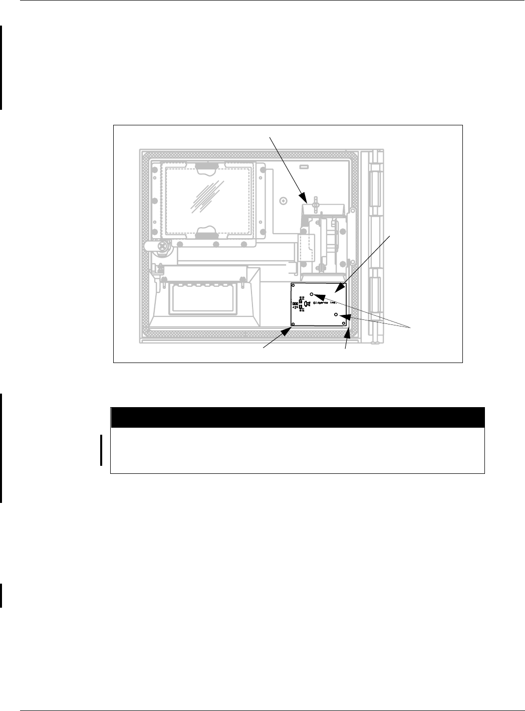
Figure 27: PCA Antenna Location
M05170A001
PCA Antenna
Card Reader
Antenna
Mounting
Holes
1/8 inch from Vertical RibFlush to Rib
Note: A graphic on the outside of the door indicates the antenna location.
Refer to Figure 23 on page 38 and ensure that the Antenna Cable is inserted into the 2-pin
Antenna connector on the Encrypted Card Reader assembly. Failure to connect the cable
properly will damage the card reader.
CAUTION
4Connect one end of the M07703A001 antenna cable to the Card Reader antenna connector of
the Encrypted Card Reader top (see Figure 23 on page 38) and the other end of the antenna
cable to the 2-pin connector on the M05170A001 PCA antenna (see Figure 27).
5Connect the other end of the antenna cable to the 2-pin RF connector on the M05170A001
PCA antenna (Figure 27).
6Dress the cables properly to avoid pinching during door opening and closing. Use Q13558-04
Cable Mounts as required.
Installation of the Encrypted Card Reader Retrofit Kit
Page 42 MDE-4635 Encrypted Card Reader Retrofit Kit (M07813K00X) Installation Manual · May 2007
Preliminary
Cold-starting the CRIND Devices using the M03651A001, A002 and
T17764 CRIND Logic Boards
To cold-start the CRIND devices, proceed as follows:
1Locate the CRIND Logic Board (s).
2Use a chip remover to remove the current firmware chip located at U7 (located directly above
connector P266).
3On side 1 of the unit, install the required firmware chip at U7 on the CRIND Logic Board.
Repeat the procedure on the other side of the unit.
4Install a jump jack on JP-19 (cold-start) on both side 1 and side 2, if you are using the
M03651A001 or A002 CRIND Logic Board. If you are using the T17764 CRIND Logic
Board install a jump jack on JP-11 (cold-start) on the CRIND Logic Boards on both sides of
the unit.
5Power-up the dispenser. At this point, both CRIND devices will cold-start and start a
download sequence. Once the download sequence starts, you can remove the jump jacks from
JP-19 or JP-11 (as applicable) on both the CRIND Logic Boards. If you wait too long, a
message will be displayed on the CRIND display prompting you to remove the jump jacks.
6Once the CRIND devices have completed the download process, they will automatically start
communicating with the POS.
RF Read performance will be severely affected by crimps/bends in the antenna cable.
IMPORTANT INFORMATION
Completing Installation for the Advantage Series Units
To complete the installation, proceed as follows:
1Install the N23951-11 UL/CA Recognition Decal on the back of the Card Reader as shown in
Figure 28 on page 43.
2Install the Cable Mounting Clamp (Q13459-01) to the rear of the Card Reader and dress cables
through it.
MDE-4635 Encrypted Card Reader Retrofit Kit (M07813K00X) Installation Manual · May 2007 Page 43
Installation of the Encrypted Card Reader Retrofit Kit
Preliminary
Figure 28: FCC Label on Smart Card Reader (Side)
Q13459-01
FCC Label
3Close and secure the main doors using the security latch and the main door lock. Reinstall and
lock the lower panel door.
4Restore power to the unit. Refer to MDE-2540 The Advantage, Legacy, and MPD Series
Owners Manual for details.
5Test the RF Readers by sliding the CRIND diagnostic card (Q12534) through both the readers
with the magnetic strip facing upwards.
6Verify if a valid read was made from the diagnostic card.
7Pass the Encrypted Card Reader test card in front of the RF antenna (flat side towards the
antenna).
8Verify if a valid read was made from the test card. The CRIND beeper will emit an audible
beep upon performing a successful read.
Note: The test card should be read from a minimum distance of 1 inch when presented parallel
to the bezel surface.
9Apply the appropriate graphic logos. These are order entry items. Refer MDE-4625 Graphics
Panel Application and Repair for graphic application instructions.
Installation of the Encrypted Card Reader Retrofit Kit
Page 44 MDE-4635 Encrypted Card Reader Retrofit Kit (M07813K00X) Installation Manual · May 2007
Preliminary
10 Obtain the FCC Decal (M02962B009) from the kit and install it under the patent label.
TRIND FCC Label Nameplate
(M02962B009)
Patent Label
Installing the M07813K008 Kit in an Advantage Series Unit Reserving Space
for Cash Acceptor (with Contactless Card Reader Option)
The installation instructions for this kit are similar to the installation instructions for the
M07813K007 kit. However, the space where the antenna should be installed should be on the
right Options door, since a cash acceptor is either being used, or the space is being reserved for
a future cash acceptor on the left Options door.
To install the M07813K008 Kit, proceed as follows:
1Remove the existing Card Reader. Refer to “Removing the Existing Card Reader” on page 35
for instructions.
2Install the Advantage Encrypted Card Reader assembly. Refer to “Installing the Advantage
Encrypted Card Reader Assembly” on page 37 for instructions.
3Install the Antenna PCA. Refer to “Installing the Antenna PCA” on page 45 for instructions.
4Cold-start the CRIND device. Refer to “Cold-starting the CRIND Devices using the
M03651A001, A002 and T17764 CRIND Logic Boards” on page 42 for details.
5Complete the installation by referring to “Completing Installation for the Advantage Series
Units” on page 42.
MDE-4635 Encrypted Card Reader Retrofit Kit (M07813K00X) Installation Manual · May 2007 Page 45
Installation of the Encrypted Card Reader Retrofit Kit
Preliminary
Installing the Antenna PCA
Note: Installation of the PCA antenna will require positioning the antenna as shown in Figure
29 on page 46. Using cloth and isopropyl alcohol, remove any dust or dirt from the
antenna location prior to removing the adhesive backing from the PCA antenna.
1Open the right side of the option door.
2Refer to Figure 29 on page 46 and mark the proposed position of the antenna on the back of
the right hand option door.
3Locate the M05170A001 Antenna PCA and the two 2 inch strips of K85492-56 foam tape in
the kit and install the two strips of foam tape to the antenna’s rear surface (non-component side
of antenna PCA). These strips may be already installed on the PCA.
4Peel the protective cover from the foam adhesive strips on the antenna and carefully position
the antenna in the position marked in the previous step (step 3) as shown in Figure 29 on page
46 and press firmly into place.
5Using the two Q11657-290 screws (part of the kit), secure the antenna in place by inserting the
screws in the mounting holes (Figure 29 on page 46) and turning the self-tapping screws into
the option door.
When drilling on the island, always use a non-sparking manual (hand) drill. Else, remove
the door and move to a safe place to drill.
CAUTION
Note: Since there are no pilot holes in the plastic for these antenna mounting screws,
significant force is typically required to get the screws to penetrate the plastic. If
problems are encountered, it is acceptable to drill a pilot hole of 1/8 inch diameter or
less, by a maximum depth of 3/16 inch to start each screw. Do not completely drill
through the plastic.
6Connect one end of the M07703A002 antenna cable to the Card Reader antenna connector of
the encrypted Card Reader top (see Figure 23 on page 38) and the other end of the antenna
cable to the 2-pin connector on the M05170A001 PCA antenna (see Figure 29 on page 46).
Installation of the Encrypted Card Reader Retrofit Kit
Page 46 MDE-4635 Encrypted Card Reader Retrofit Kit (M07813K00X) Installation Manual · May 2007
Preliminary
Figure 29: Antenna PCA Location on the Right Side of the Option Door
M05170A001
Antenna PCA
Antenna
Mounting
Holes
2-pin Connector
Right Hand Door
(backside)
3.75”
Flush to Rib
Figure 30: Antenna PCA Mounted on the Right Side Option Door
M04124A004
Antenna
Cable
M05170A001
Antenna PCA
Refer to Figure 29 on page 46 and Figure 30 on page 46 and ensure that the Antenna Cable is
inserted into the 2-pin Antenna connector on the dual-head card assembly. Failure to connect
the cable properly will damage the card reader.
CAUTION
MDE-4635 Encrypted Card Reader Retrofit Kit (M07813K00X) Installation Manual · May 2007 Page 47
Installation of the Encrypted Card Reader Retrofit Kit
Preliminary
7Use the cable mounts (Q13558-04) to properly dress the cables, to avoid pinching or excessive
stretching during opening/closing of either or both doors (see Figure 29 on page 46).
RF Read performance will be severely affected by crimps/bends in the antenna cable.
IMPORTANT INFORMATION
Figure 31: Cable Properly Dressed from the Antenna to the Card Reader
(Looking at the Rear of the Right Door with the Door Closed)
Antenna CableAntennaCable Clamps
8Repeat the steps 1 to 7 for the other side of the unit.

Installation of the Encrypted Card Reader Retrofit Kit
© 2007 Gilbarco Inc.
7300 West Friendly Avenue · Post Office Box 22087
Greensboro, North Carolina 27420
Phone (336) 547-5000 · http://www.gilbarco.com · Printed in the U.S.A.
MDE-4635 Encrypted Card Reader Retrofit Kit (M07813K00X) Installation Manual · May 2007
Preliminary
CRIND®, TRIND®, Eclipse®, Encore®, Infoscreen®, MPD®, Legacy®, and The Advantage® Series are registered trademarks of Gilbarco Inc.
CIM™ and SmartPad™ are trademarks of Gilbarco Inc. Express PaySM is a service mark of American Express Co. MasterCard® is a registered
trademark of MasterCard International, Inc. PayPass™ is a trademark of MasterCard International, Inc.
Installing the M07813K009 Kit in an Advantage Series Unit Using Space
Reserved for Cash Acceptor on the Left Options Door (without Contactless
Card Reader Option)
The installation instructions for this kit are similar to the installation instructions for the
M07813K007 kit. The difference is that there is no Contactless Card Reader option.
To install the M07813K009 kit, proceed as follows:
1Remove the existing Card Reader. Refer to “Removing the Existing Card Reader” on page 35
for instructions.
2Install the Advantage Encrypted Card Reader assembly. Refer to “Installing the Advantage
Encrypted Card Reader Assembly” on page 37 for instructions.
3Cold-start the CRIND device. Refer to “Cold-starting the CRIND Devices using the
M03651A001, A002 and T17764 CRIND Logic Boards” on page 42 for details.
4Complete the installation by referring to “Completing Installation for the Advantage Series
Units” on page 42.
Note: Do not perform steps 5 to 10.
5Verify that the Card Reader will read a card.