Gilbarco GBIRA Radio Frequency Identification Device User Manual
Gilbarco Inc. Radio Frequency Identification Device
UserManual.wiki
>
Gilbarco
>
GBIRA User Manual
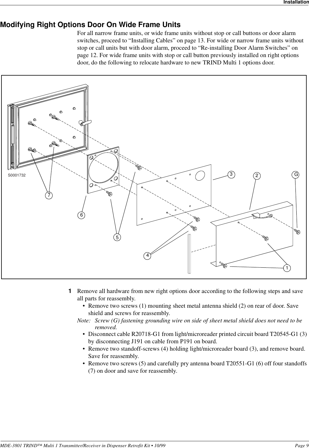
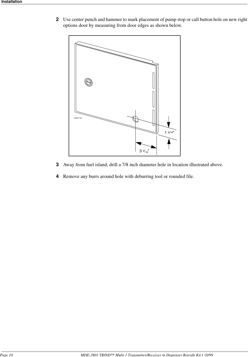
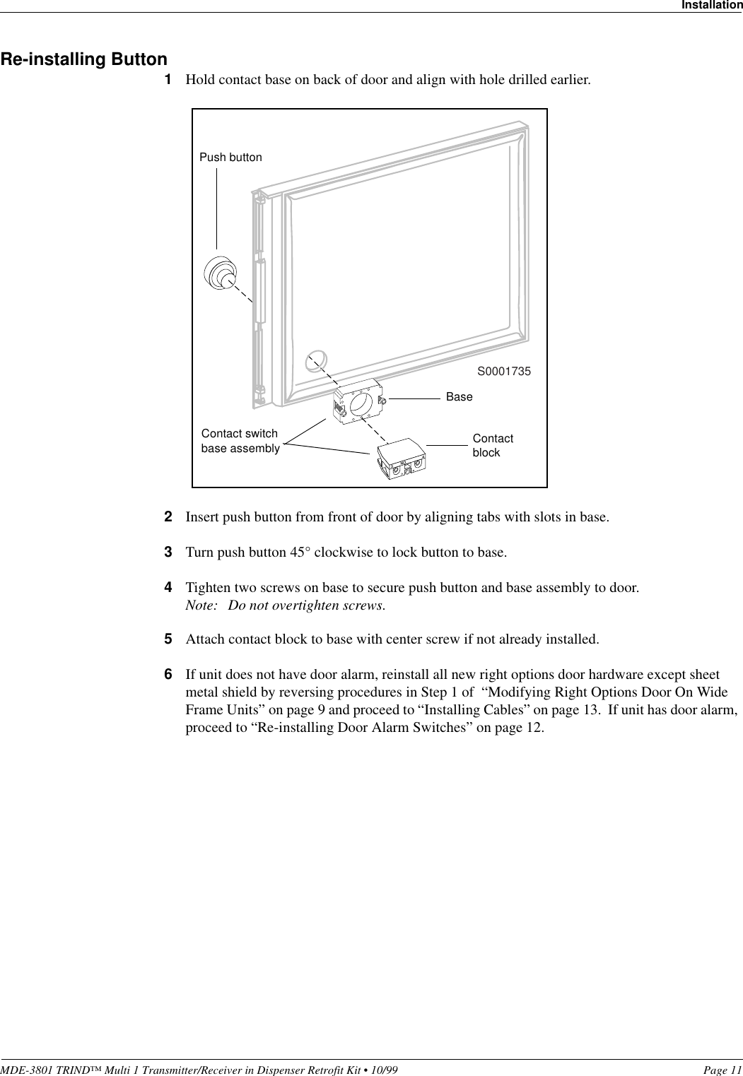
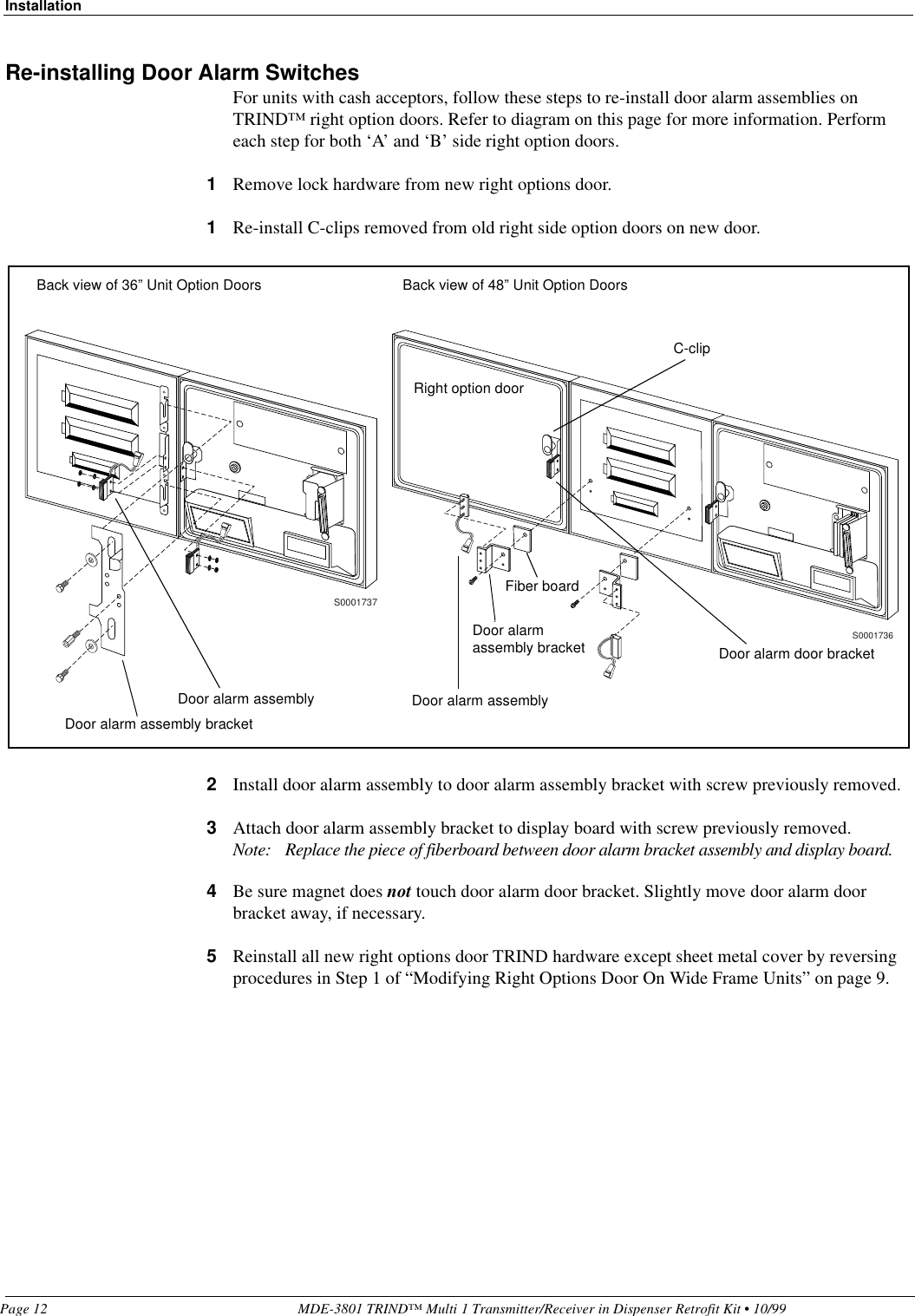
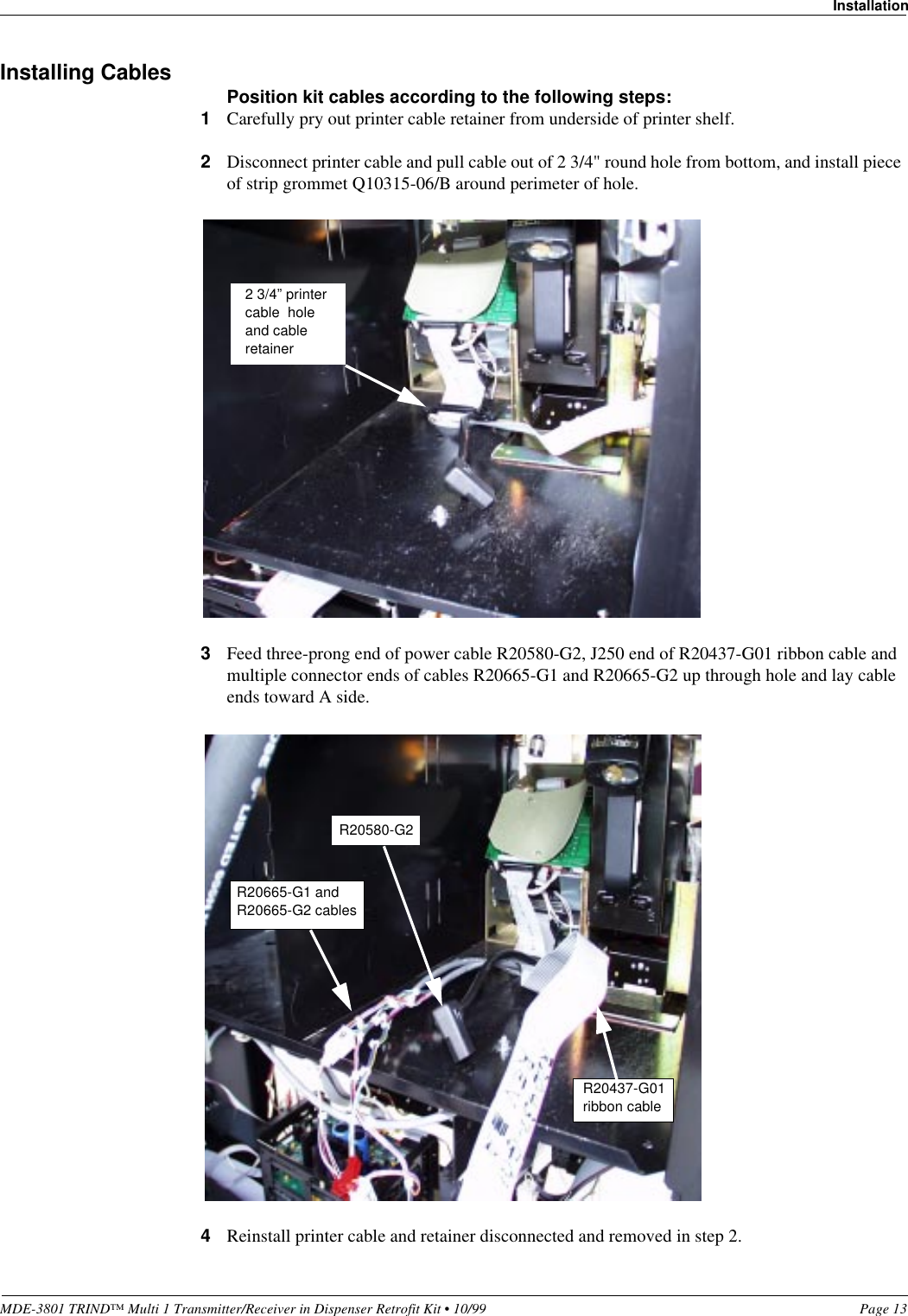
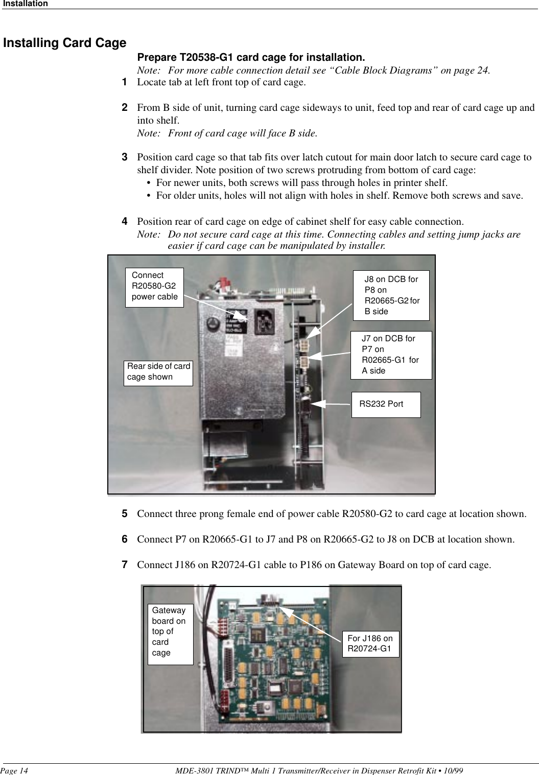
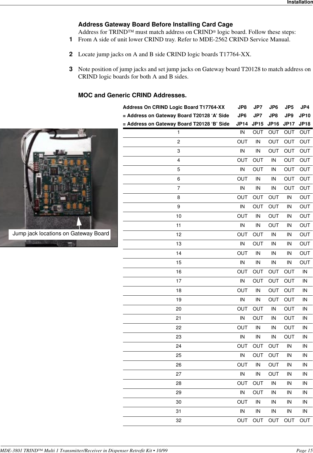
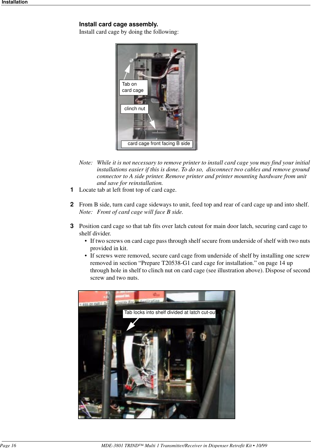
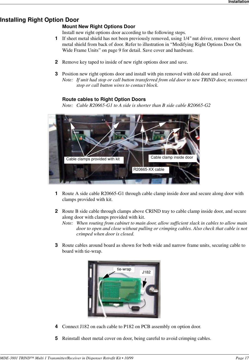
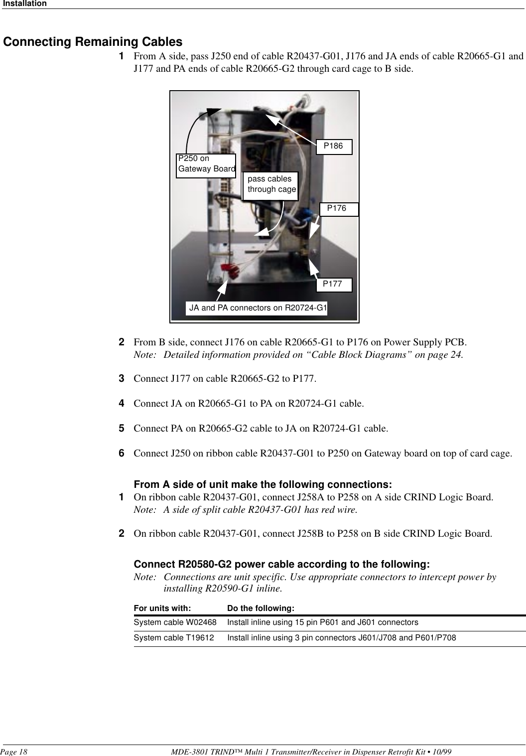
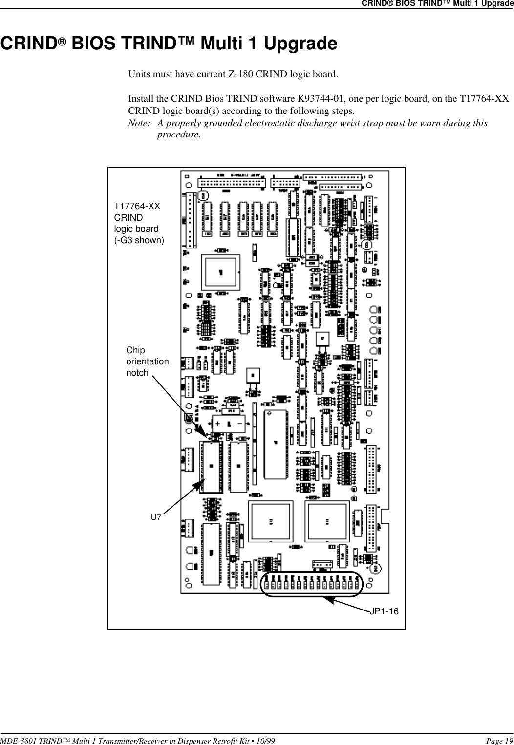
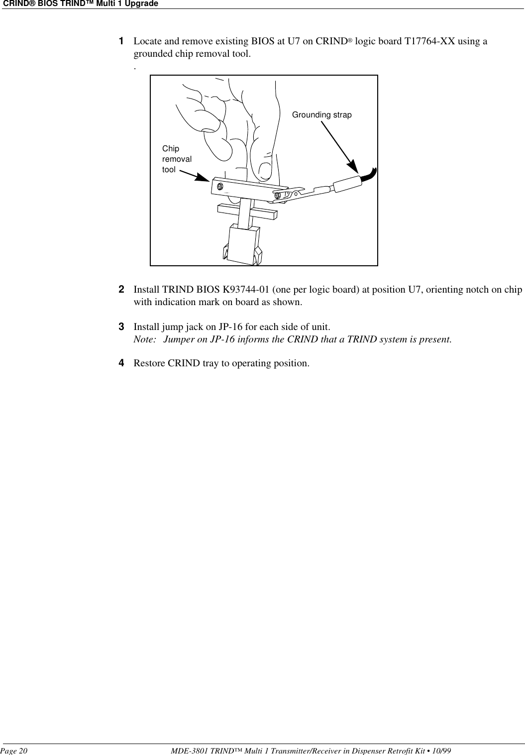
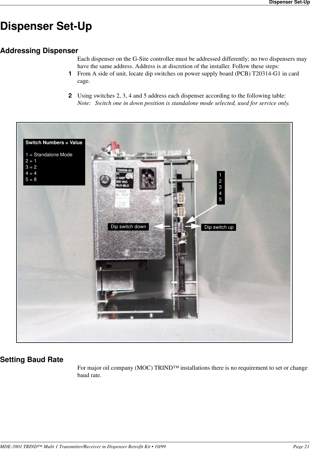
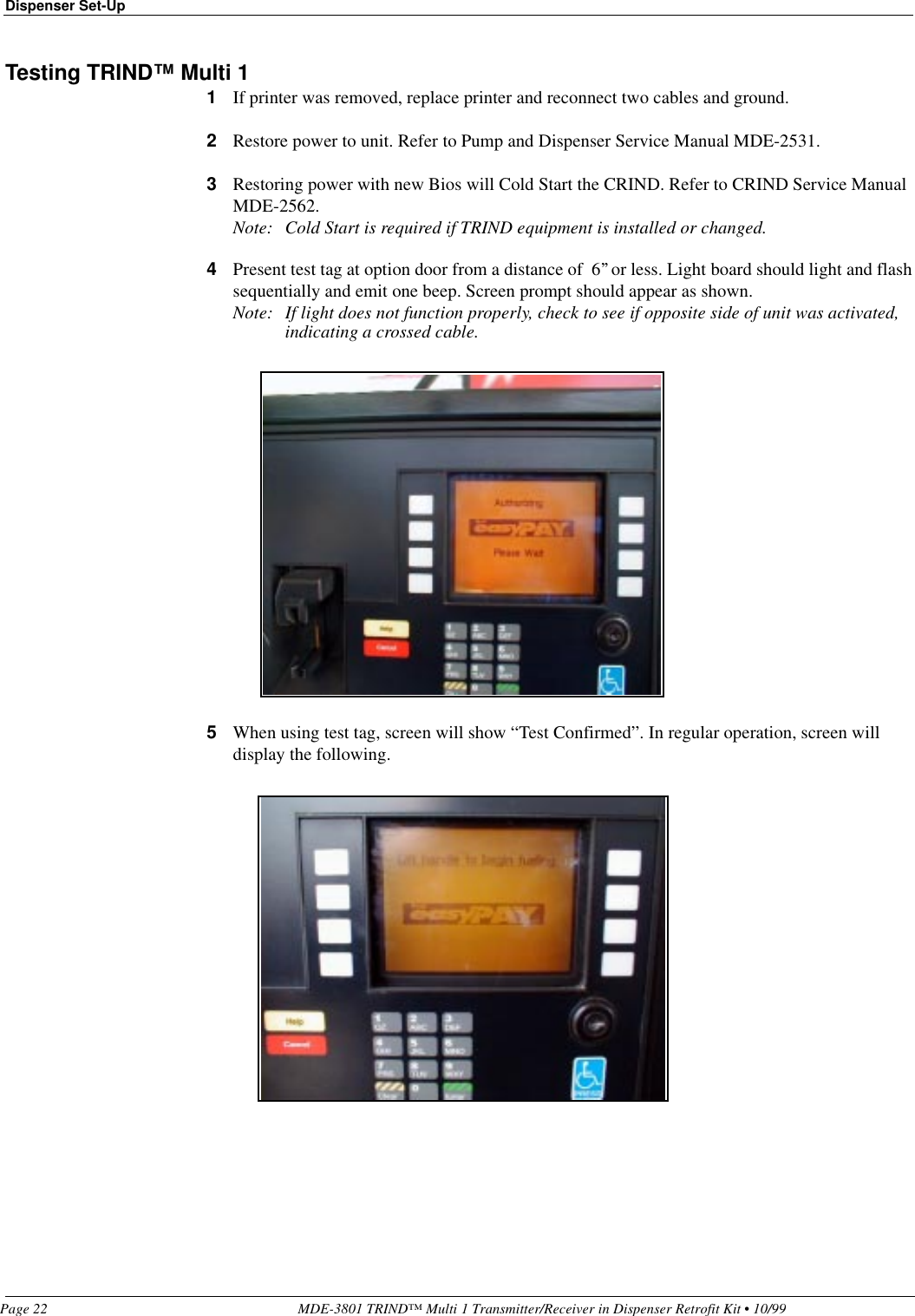
installation instructions
Navigation menu
Upload a User Manual
Namespaces
Wiki Guide
HTML
PDF
Info
Views
User Manual
Discussion / Help
Navigation